EP4027178A1 - Retroreflektierende zusammengesetzte reflektierende mikrokugeln und reflektierendes anorganisches material - Google Patents
Retroreflektierende zusammengesetzte reflektierende mikrokugeln und reflektierendes anorganisches material Download PDFInfo
- Publication number
- EP4027178A1 EP4027178A1 EP22151070.4A EP22151070A EP4027178A1 EP 4027178 A1 EP4027178 A1 EP 4027178A1 EP 22151070 A EP22151070 A EP 22151070A EP 4027178 A1 EP4027178 A1 EP 4027178A1
- Authority
- EP
- European Patent Office
- Prior art keywords
- bead
- composite
- peripheral
- retroreflective
- glass
- Prior art date
- Legal status (The legal status is an assumption and is not a legal conclusion. Google has not performed a legal analysis and makes no representation as to the accuracy of the status listed.)
- Granted
Links
Images

Classifications
-
- G—PHYSICS
- G02—OPTICS
- G02B—OPTICAL ELEMENTS, SYSTEMS OR APPARATUS
- G02B5/00—Optical elements other than lenses
- G02B5/12—Reflex reflectors
- G02B5/126—Reflex reflectors including curved refracting surface
- G02B5/128—Reflex reflectors including curved refracting surface transparent spheres being embedded in matrix
-
- B—PERFORMING OPERATIONS; TRANSPORTING
- B05—SPRAYING OR ATOMISING IN GENERAL; APPLYING FLUENT MATERIALS TO SURFACES, IN GENERAL
- B05D—PROCESSES FOR APPLYING FLUENT MATERIALS TO SURFACES, IN GENERAL
- B05D5/00—Processes for applying liquids or other fluent materials to surfaces to obtain special surface effects, finishes or structures
- B05D5/06—Processes for applying liquids or other fluent materials to surfaces to obtain special surface effects, finishes or structures to obtain multicolour or other optical effects
- B05D5/061—Special surface effect
- B05D5/063—Reflective effect
-
- B—PERFORMING OPERATIONS; TRANSPORTING
- B29—WORKING OF PLASTICS; WORKING OF SUBSTANCES IN A PLASTIC STATE IN GENERAL
- B29D—PRODUCING PARTICULAR ARTICLES FROM PLASTICS OR FROM SUBSTANCES IN A PLASTIC STATE
- B29D11/00—Producing optical elements, e.g. lenses or prisms
- B29D11/00605—Production of reflex reflectors
-
- C—CHEMISTRY; METALLURGY
- C03—GLASS; MINERAL OR SLAG WOOL
- C03C—CHEMICAL COMPOSITION OF GLASSES, GLAZES OR VITREOUS ENAMELS; SURFACE TREATMENT OF GLASS; SURFACE TREATMENT OF FIBRES OR FILAMENTS MADE FROM GLASS, MINERALS OR SLAGS; JOINING GLASS TO GLASS OR OTHER MATERIALS
- C03C11/00—Multi-cellular glass ; Porous or hollow glass or glass particles
- C03C11/002—Hollow glass particles
-
- C—CHEMISTRY; METALLURGY
- C03—GLASS; MINERAL OR SLAG WOOL
- C03C—CHEMICAL COMPOSITION OF GLASSES, GLAZES OR VITREOUS ENAMELS; SURFACE TREATMENT OF GLASS; SURFACE TREATMENT OF FIBRES OR FILAMENTS MADE FROM GLASS, MINERALS OR SLAGS; JOINING GLASS TO GLASS OR OTHER MATERIALS
- C03C12/00—Powdered glass; Bead compositions
-
- C—CHEMISTRY; METALLURGY
- C03—GLASS; MINERAL OR SLAG WOOL
- C03C—CHEMICAL COMPOSITION OF GLASSES, GLAZES OR VITREOUS ENAMELS; SURFACE TREATMENT OF GLASS; SURFACE TREATMENT OF FIBRES OR FILAMENTS MADE FROM GLASS, MINERALS OR SLAGS; JOINING GLASS TO GLASS OR OTHER MATERIALS
- C03C12/00—Powdered glass; Bead compositions
- C03C12/02—Reflective beads
-
- C—CHEMISTRY; METALLURGY
- C03—GLASS; MINERAL OR SLAG WOOL
- C03C—CHEMICAL COMPOSITION OF GLASSES, GLAZES OR VITREOUS ENAMELS; SURFACE TREATMENT OF GLASS; SURFACE TREATMENT OF FIBRES OR FILAMENTS MADE FROM GLASS, MINERALS OR SLAGS; JOINING GLASS TO GLASS OR OTHER MATERIALS
- C03C17/00—Surface treatment of glass, not in the form of fibres or filaments, by coating
- C03C17/006—Surface treatment of glass, not in the form of fibres or filaments, by coating with materials of composite character
- C03C17/008—Surface treatment of glass, not in the form of fibres or filaments, by coating with materials of composite character comprising a mixture of materials covered by two or more of the groups C03C17/02, C03C17/06, C03C17/22 and C03C17/28
-
- C—CHEMISTRY; METALLURGY
- C03—GLASS; MINERAL OR SLAG WOOL
- C03C—CHEMICAL COMPOSITION OF GLASSES, GLAZES OR VITREOUS ENAMELS; SURFACE TREATMENT OF GLASS; SURFACE TREATMENT OF FIBRES OR FILAMENTS MADE FROM GLASS, MINERALS OR SLAGS; JOINING GLASS TO GLASS OR OTHER MATERIALS
- C03C25/00—Surface treatment of fibres or filaments made from glass, minerals or slags
- C03C25/10—Coating
- C03C25/42—Coatings containing inorganic materials
- C03C25/46—Metals
-
- C—CHEMISTRY; METALLURGY
- C03—GLASS; MINERAL OR SLAG WOOL
- C03C—CHEMICAL COMPOSITION OF GLASSES, GLAZES OR VITREOUS ENAMELS; SURFACE TREATMENT OF GLASS; SURFACE TREATMENT OF FIBRES OR FILAMENTS MADE FROM GLASS, MINERALS OR SLAGS; JOINING GLASS TO GLASS OR OTHER MATERIALS
- C03C27/00—Joining pieces of glass to pieces of other inorganic material; Joining glass to glass other than by fusing
- C03C27/06—Joining glass to glass by processes other than fusing
-
- E—FIXED CONSTRUCTIONS
- E01—CONSTRUCTION OF ROADS, RAILWAYS, OR BRIDGES
- E01F—ADDITIONAL WORK, SUCH AS EQUIPPING ROADS OR THE CONSTRUCTION OF PLATFORMS, HELICOPTER LANDING STAGES, SIGNS, SNOW FENCES, OR THE LIKE
- E01F9/00—Arrangement of road signs or traffic signals; Arrangements for enforcing caution
- E01F9/50—Road surface markings; Kerbs or road edgings, specially adapted for alerting road users
- E01F9/506—Road surface markings; Kerbs or road edgings, specially adapted for alerting road users characterised by the road surface marking material, e.g. comprising additives for improving friction or reflectivity; Methods of forming, installing or applying markings in, on or to road surfaces
- E01F9/524—Reflecting elements specially adapted for incorporation in or application to road surface markings
Definitions
- the embodiments of this application relate generally to reflective or retroreflective composites that can be used in useful applications such as in reflective indicia or articles.
- Another retroreflective element construction uses silvered glass flakes as a specular reflector on the surface of a spherical polymeric core; no spherical optical elements are used.
- Still another known construction has a retroreflective element with a plastic globule refracting incident light onto a layer of glass optical elements attached to the bottom of the globule. The glass optical elements focus light onto a specular coating or film located below the elements. Incident light is then reflected along the original path towards the source.
- yield refers to the amount of the product that is damageed in some aspect in the manufacture of the retroreflective material or in the manufacture of its end use resulting in loss of retroreflectivity.
- Existing materials also have a fixed lifetime in the use environment requiring repeat applications.
- U.S. Pat. Nos. 5,670,209 ; 5,750,191 ; 5,774,265 ; 5,942,280 ; 7,513,941 ; 8,591,044 ; 8,591,045 ; 8,292,539 and U.S. Pat. App. Pubs. 2005/00100709 ; 2005/0158461 ; 2011/01770193 ; 2017/0242165 ; 2018/0291175 disclose bead technology.
- a retroreflective object or retroreflective composite comprising a substrate core bead with an array of smaller peripheral beads or microspheres surrounding, fused with, or bonded to the core bead, imbedded but revealed in a single layer with a fused layer.
- a retroreflective composite comprising, a sintered object comprising a core bead and a peripheral bead bonded by an interphase layer.
- an interphase as a coating composition
- IM interfacial modifier
- a reflective inorganic pigment and a finely divided glass particulate (having a particle size less than the peripheral bead) promotes the rapid and uniform formation of a single layer of peripheral beads substantially bonded to and surrounding the core bead.
- the peripheral bead and the reflective inorganic cooperate to collect and to reflect light efficiently.
- the fused nature of the retroreflective composite provides a durable robust retroreflective composite that can survive a harsh use environment. We have seen that virtually the entire surface of the core bead can be covered with the peripheral bead (microsphere).
- peripheral beads can cover the surface of the core bead leaving small gaps and in certain circumstances, minor amounts of the peripheral bead can form on the substantially complete single layer of peripheral beads.
- the core bead can be clear and have a refractive index but also can be substantially translucent or even opaque.
- the core bead can add to retroreflectivity but is not needed for basic performance.
- composite refers to a combination of core bead, and a plurality of smaller peripheral beads with an initial coating composition (pre-sinter) or interphase layer (post-sinter) and surrounding each core bead.
- optical index means the ratio of the velocity of light in a vacuum to its velocity in a specified medium, in this case glass compositions. See ASTM E1967-19 for test.
- retroreflective means that the reflection of incident light on an object is substantially directed in a vector back to the source.
- coating refers to an either (i) a blend of an interfacial modifier (IM), an inorganic pigment and a finely divided glass particulate (having a particle size less than the peripheral bead) or (ii) to the addition of a layer comprising an interfacial modifier.
- IM interfacial modifier
- an organo-metallic material that can be used in combination to coat the surface of any part of the core bead or peripheral bead, or glass particulate and does not react with the other components of the solid particles or with itself.
- An IM coated substrate is non-reactive with itself and/or other uncoated substrates.
- the IM is an organo-metallic compound.
- an organo-metallic interfacial modifier comprises a group IVA or IVB metal with organic substituents.
- the coating containing pigment, an IM and glass participates in the formation of the initial composite that is sintered to form the final retroreflective composite.
- the upon sinter, coating forms a "residue" in the retroreflective composite.
- the residue can contain at least in part the metal component of the IM.
- the retroreflective composite is substantially free of any organic materials in the residue.
- the "peripheral bead” is a microsphere spherical object of substantially smaller diameter than the core bead that is arrayed upon the surface of the core bead.
- glass particulate is a finely divided glass with a particle size substantially smaller than the peripheral bead.
- the peripheral bead and the glass particulate are different materials that provide different functions.
- the peripheral bead is a part of the retroreflective composite.
- the glass particulate is part of the interphase layer that bonds the peripheral bead to the core bead.
- the peripheral bead is not substantially changed in sintering but the glass particulate typical fuses as a part of the interphase.
- a “retroreflective composite” or “composite” is a central core bead with an array of peripheral beads or microspheres on its surface bonded with an interphase layer.
- the term "self-ordered” is the packing of substantially the same size peripheral bead as a monolayer, and array, on the periphery of the core bead.
- the density of the monolayer over the periphery is often greater than 50, 60, 70, 80 or 90% of the surface area of the periphery of the core bead.
- sinter refers to a process in which a particulate or blend thereof is heated to a temperature that causes particle to particle binding to form a solid.
- the particle itself does not melt but may soften and the energy of surface atoms on the core bead periphery and particulate causes atomic migration or diffusion among particles to form bonds that cause a fusion, bonding, or solidification among adjacent particles.
- the metal component of the interfacial modifier remains as a part of surface distribution, component or coating derived from the interfacial modifier reagent.
- fusion means that the central bead and the array of peripheral beads form a robust mechanically stable structure with the other optional components such as, for example, magnetic and abrasive components.
- the structure can be assembled and sintered with substantial yield and can be combined into a retroreflective end use object with minimal structural damage to itself and with a substantial yield of useful end products.
- the bond is formed by sintering wherein atoms from both the central and peripheral bead, glass particulate and other coating materials combine in a fusion layer.
- the bond is formed at a temperature below the melting point of the core bead, such as glass, and the peripheral bead retain their spherical nature.
- the bond can comprise an alloy structure or a structure formed as atoms from the coating, peripheral bead and core bead diffuses on into the other into the bond structure therebetween.
- the core bead, peripheral beads, and other components are arrayed and fused or bonded to on the periphery of the core bead using the unique interphase layer coating.
- This arrangement presents a layer of peripheral beads for light to be transmitted, reflected, and refracted back to the source.
- Embodiments can be seen including but not limited to the following:
- coatings are used to make a reflective and robust retroreflective composite that can be manufactured in high yields and can maintain reflectivity in a variety of use environments.
- a first fused coating is formed on the substrate.
- a second coating can be formed onto the fused layer. The combination of layers, during sintering, fuses and bonds the microspheres to the substrate.
- a first coating composition of the interfacial modifier can be combined with a second component comprising an inorganic pigment material and a third glass component comprising a finely divided glass powder or particulate (particle size smaller than the peripheral bead).
- the multi-component coating has the capacity to promote the interaction between the core bead and peripheral beads to form the array of peripheral beads onto the core bead before sintering.
- the coating composition when sintered promotes the fusion or bonding between the peripheral beads and the core beads.
- the inorganic pigment as stated above, depending on concentration can color the bead and act to increase the opacity of the central bead rendering them translucent or substantially opaque. Minimal pigment leaves the core nearly transparent.
- the glass particulate in the coating composition at sintering temperatures promotes the glass-to-glass bonding of the peripheral beads to the fused coating layer utilizing at least some amount of the peripheral bead, glass particulate and IM to co-operate in the bonding.
- the term "neat" indicates that there is no continuous phase solvent or dispersed dispersion liquid such as a continuous organic solvent or aqueous phase.
- a second or third coating or more to obtain this dimension can be applied to the fused layer.
- One useful second layer is a liquid interfacial modifier that can initially bond the peripheral beads to the substrate forming a substantially single layer of array of smaller peripheral beads. This initial assembly composite is sintered into the final product.
- the thickness of the final interphase layer is related to the diameter of the peripheral bead. The interphase layer cannot be so thick that the bead is covered by the layer. Sufficient of the diameter of the peripheral bead should be revealed above the surface of the layer to maintain effective retroreflective properties.
- Interfacial modifier (IM) component used in either coating
- An interfacial modifier can be used to initially form a self-ordered monolayer layer coating of the peripheral beads that covers the surface of the core bead.
- the initial large and small bead construct can be heated to sinter temperature to fuse the smaller peripheral bead to the core bead and to form the fused interphase layer.
- the resulting fused bond includes mass from the peripheral beads, the core bead, the glass particulate, and any generally inorganic component of the coating.
- the IM both obtains the self-ordered coating and can promote formation of the sintered fusion bonding.
- the appropriate interfacial modifier for manufacturing retroreflective article can be measured by monitoring the temperature of the sintering process in which the bead and the microsphere are fused to melt the coating but not the beads.
- Interfacial modifiers used in the application fall into broad categories including Group IIIA, or Group VIB element compounds, for example, titanate compounds, zirconate compounds, hafnium compounds, samarium compounds, strontium compounds, neodymium compounds, yttrium compounds, phosphonate compounds, aluminate compounds and zinc compounds.
- Aluminates, boronates, phosphonates, titanates and zirconates that are useful contain from about 1 to about 3 ligands comprising hydrocarbyl phosphate esters and/or hydrocarbyl sulfonate esters and about 1 to 3 hydrocarbyl ligands which may further contain unsaturation and heteroatoms such as oxygen, nitrogen, and sulfur
- the interfacial modifier that can be used is a type of organo-metallic material such as organo-cobalt, organo-iron, organo-boron, organo-nickel, organo-titanate, organo-aluminate organo-strontium, organo-neodymium, organo-yttrium, organo-zinc, or organo-zirconate.
- organo-metallic material such as organo-cobalt, organo-iron, organo-boron, organo-nickel, organo-titanate, organo-aluminate organo-strontium, organo-neodymium, organo-yttrium, organo-zinc, or organo-zirconate.
- organo-titanate organo-aluminates, organo-boronate, organo-strontium, organo-neodymium, organo-yttrium, organo-zirconates which can be used, and which can be referred to as organo-metallic compounds are distinguished by the presence of at least one hydrolysable group and at least one organic moiety. Mixtures of the organo-metallic materials may be used.
- the mixture of the interfacial modifiers or the IM/TiO2 (pigment)/glass particulate coating may be variously applied, which means at one or more than one or more than one coating may be applied, to different core beads or peripheral beads or glass particulate with various size distributions.
- M is a central atom selected from such metals as, for example, Ti, Al, and Zr and other metal centers;
- R 1 is a hydrolysable group;
- R 2 is a group consisting of an organic moiety, preferably an organic group that is non-reactive with polymer or other film former; wherein the sum of m+n must equal the coordination number of the central atom and where n is an integer ⁇ 1 and m is an integer ⁇ 1.
- Particularly R 1 is an alkoxy group having less than 12 carbon atoms.
- Other useful groups are those alkoxy groups, which have less than 6 carbons, and alkoxy groups having 1-3 C atoms.
- R 2 is an organic group including between 6-30, preferably 10-24 carbon atoms optionally including one or more hetero atoms selected from the group consisting of N, O, S and P.
- R 2 is a group consisting of an organic moiety, which is not easily hydrolyzed and is often lipophilic and can be a chain of an alkyl, ether, ester, phospho-alkyl, phospho-alkyl, phospho-lipid, or phospho-amine.
- the phosphorus may be present as phosphate, pyrophosphato, or phosphito groups.
- R 2 may be linear, branched, cyclic, or aromatic.
- R 2 is substantially unreactive, i.e., not providing attachment or bonding, to other particles.
- Titanates provide antioxidant properties and can modify or control cure chemistry.
- a titanate material can be 2-propanolato, tris iso-octa-decanato-O-titanium IV, an isopropyl tri-isostearoyl titanate.
- Zirconate provides excellent coating and reduces formation of off color in formulated thermoplastic materials.
- a useful zirconate material is neopentyl (diallyl) oxy-tri (dioctyl) phosphato-zirconate.
- an interfacial modifier results in workable viscosity and improved structural properties in a final use such as a structural member or shaped article.
- Minimal amounts of the modifier can be used including about 0.005 to10 wt.-%, about 0.01 to 8 wt.-%, about 0.05 to 6 wt.-%, or about 0.04 to 2 wt.% based on the weight final retroreflective composite.
- the IM coating can be formed as a coating of a dimension equal to at least 3 molecular layers of IM.
- a substantially complete IM coating has a thickness of less than 1500 Angstroms often less than 200 Angstroms, and commonly 100 to 5000 Angstroms ( ⁇ ) 50 to 1000 Angstroms ( ⁇ ) or 10 to 500 Angstroms ( ⁇ ).
- the retroreflective object is manufactured using a first coating to ensure forming an array between the peripheral bead and the core bead.
- the resulting product is then further coated with a second, optionally different, coating.
- the first ensures a quality bond between the microsphere and the bead whereas the second interfacial modifier ensures that the resulting product is fully compatible with any polymer material that may be used in an application such as a paint, tape, or film.
- Non-spherical glass ground and sifted to less than 25 ⁇ have also proven useful and are especially cost effective.
- the finely divided glass particulate used in the coating comprises a particle size substantially smaller than the peripheral bead and is a composition that can be dispersed in the final coating composition.
- the chemistry of the glass particulate and the core beads can be identical such that the glass particulate and the core bead are similar in glass composition that increases processability. See ASTM E2651-19 for test.
- the Inorganic pigment is used to provide at least some minimal
- the inorganic reflective mineral pigment is used in the retroreflective object to provide some capacity for reflecting incident light.
- These inorganic reflective mineral pigments are typically platelike or planar in appearance have a major diameter of 0.1 to 20 ⁇ .
- These materials have no symmetrical exterior perimeter but can be very irregular, non-circular structures. These minerals are typically thin platelike planar particulate typically found in the environment but can be synthesized.
- the minerals are typically nonmetallic in that they are not made from metals and have no metallic coatings. Typically, these minerals contain sodium, potassium, calcium, barium, or often rubidium or cesium species, combined with aluminum, magnesium, iron, or other species with oxide, hydroxyl, or fluorine anionic species. These minerals are typically chemically inert, somewhat flexible, lightweight, reflective, and can be transparent, translucent, or opaque, but must maintain reflective characteristics. These minerals are typically stable at elevated temperatures such as the temperatures used in centering the retroreflective objects and are often stable to 500 to 1,600° C.
- the resulting mica pigment produces a reflective color depending on the thickness of the coating and it can reflect a white light including all the visible spectra.
- coated micas are made from mica and from about 0.1 to about 30 weight percent of the coating material.
- Commercial useful micas are phlogopite, or muscovite or similar groupings.
- the claimed retroreflective composite bead has a peripheral bead and a core bead.
- the peripheral bead is always smaller than the core bead and has a diameter such that a plurality of peripheral beads can form a layer of beads distributed on interphase on the core bead.
- glass beads used within the embodiments can include both solid and hollow glass spheres.
- the ratio of diameters of the larger core beads to the peripheral beads is greater than 5:1, 10:1, 100:1, 200:1, or 254:1.
- the peripheral bead components cover the core bead component in an array (i.e.) substantially a monolayer over the surface of the central component.
- the surface array comprises about 50 to 100 %, 60 to 98 %, 70 to 97%, or 80 to 96% of coverage in a substantial monolayer.
- Both the central component and the peripheral bead components are of generally spherical configuration.
- Solid glass beads or spheres (including both hollow spheres and microspheres and solid particulate) are useful materials in the embodiments. These spheres are strong enough to avoid being crushed or broken during further processing, such as by high pressure spraying, kneading, extrusion, or injection molding. In some embodiments these spheres have particle sizes close to the sizes of other particulate if mixed as one material.
- the retroreflective bead object either large central bead component or the small bead peripheral bead component, include at least one of silica or alumina.
- the silica can be, for example, fumed silica, precipitated silica, surface modified silica, or nano-silica.
- the retroreflective bead object can comprise glass beads comprising aluminosilicate, boron trioxide, borophophosilicate, borosilicate, barium titanate, cobalt, fluorophosphate, fluorosilicate, germanium dioxide, lead glass, opaline glass, soda lime, sodium hexametaphosphate, sodium silicate, tellurite, thoriated glass, uranium glass, or vitrite.
- the use of these glass compositions or their mixtures are to provide specific characteristic to the glass bead media such as coloring, marking, durability, cost etc.
- the peripheral bead can be less than 300, can be about 1 to 250 ⁇ or 10 to 200 ⁇ and can be about 20 to 150 ⁇ .
- the peripheral bead must maintain a substantial index of refraction that can range from about 1.5 to 3.0.
- these peripheral beads can have a refractive index that ranges from about 1.5 to about 2.6.
- the claimed retroreflective composite structure comprises a substrate or core bead with a surface covered with adhered smaller peripheral beads. Once the structure is assembled, it is sintered to ensure that the core bead and plurality of peripheral beads are mechanically attached, bonded to, or fused to the substrate core bead with the coating.
- the retroreflectivity of the structure primarily comes from the optical character of the peripheral beads in or on the surface.
- the interphase layer can be formed by the application of the coating materials in one, two, three, four or more coatings to form a uniform interphase layer with the components distributed in substantially uniform layer. In each coating step the interphase coating materials can be added serially or in any combinations.
- an interfacial modifier can then be added to the fused layer and a plurality of the peripheral bead can then be contacted with the coated surface of the substrate core bead and due to the action of the coating, the peripheral bead forms an ordered and substantially complete coverage of the sintered coating on the peripheral bead.
- the peripheral bead can be coated with interfacial modifier prior to contacting the peripheral bead with the core bead. However, if sufficient coating is added to the substrate or core bead, additional coating on the peripheral bead is optional. Once the peripheral bead forms the ordered and complete coverage on the core bead, the structure is sintered at elevated temperature to ensure that the peripheral bead is bonded, fused, or mechanically attached to the coated core bead revealing a retro reflective surface.
- a mixture of the core bead, the inorganic materials and IM can be made, and that retroreflective composite can be cured followed by application and sintering of the peripheral bead. After the first mixture is formed additional coating material can be layered on the retroreflective composite.
- a process for forming a retroreflective composite comprising coating a core bead with a dispersion of an inorganic pigment, a glass particulate, and an interfacial modifier to make an initial mixture; sintering the initial mixture to form a fused interphase layer. Coating the interphase with an interfacial modifier followed by a peripheral bead to from an initial combination; and sintering the composite bead to form a sintered composite bead; wherein the core bead, the dispersion and the peripheral bead form a robust, mechanically stable bond between the peripheral bead and the core bead.
- additional coating material can be layered on the composite.
- the IM coatings on the fused layer reduces the van der Waals repulsion, decreases free energy of the system and increases the surface tension also causing capillary attraction. The combination of these effects is believed to cause an ordered array due to the coating layer. In the absence of the coating the peripheral bead does not readily associate with the other components in the article.
- the IM coating also maintains the stability of the peripheral layer until the retroreflective composite is sintered to obtain a fused and bonded peripheral layer on the core bead.
- the steps in making the retroreflective composite bead are 1) preparation of the core bead and peripheral bead components being used for making the retroreflective bead, 2) coating the large central bead component and, optionally, the smaller microsphere peripheral bead components with coating, 3) mixing the interphase components with the large bead components 4) sintering the coated central bead 5) coating the fused layer with IM and obtaining a substantially complete, single layer, self-ordered array of the small bead peripheral components onto the IM on large bead central components; and 6) sintering the core bead and peripheral bead components to form a large fused retroreflective composite bead, bonding the ordered array of a plurality of peripheral beads onto the core bead's exterior surface.
- the core bead component is well covered with the smaller peripheral beads on the surface of the large bead component through the effect of the coating on the surface of the large bead component.
- the coverage of the array of small microsphere peripheral bead component over the large microsphere central bead component of the retroreflective composite is a single ordered layer, monolayer, of the smaller peripheral beads on each of the core beads.
- An ordered array of the small bead component on the interfacially modified surface of the large bead can be greater than 50, 60, 70, 80, 90, or 95% of the surface area of the large bead.
- the process to make the retroreflective composite commences with collecting a supply of largely spherical core glass central bead or component referred to sometimes herein as "bead” or "sphere".
- Suitable amounts of the coating can be added to the large central beads and the resulting combination is mixed until the large beads have a controlled exterior coating that is substantially a continuous and uniform layer over the bead surface periphery.
- the initial fused coating is sintered and then coated with IM.
- the smaller peripheral glass beads, optionally with an IM coating, that are generally spherical or at least rounded in form, are added to the mixture of large beads coated with the interfacial modifier and the resulting new mixture of interfacially modified coated large beads and small beads are blended.
- a plurality of the smaller beads is ordered as a monolayer on the surface of the core beads.
- the coated bead is heated to fuse the microspheres to the central bead.
- the fused bead is further coated with a polymer compatible IM that enables the bead to form useful retroreflective installations with a polymer.
- all the processing including mixing of the various beads and coatings, the time for the interfacial modifier to cover the surfaces of the initial group of core beads and for self-ordering of the small beads to associate the small spherical glass members to the interfacially modifier surface of the core beads to form the retroreflective composite occurs in reasonable period.
- the retroreflective composite comprises a core bead central generally spherical glass components with each core bead having a plurality of smaller peripheral bead generally spherical glass components heat bonded to the central bead components.
- the heat bonded retroreflective composite provided will retroreflect any color, such as, for example, either white or yellow, according to the pigment(s) selected for incorporation into the highway marker, or other pigments that may be incorporated into countertops or safety equipment.
- the driving force is the combination of atoms at the interphase and a reduction in the system free energy, manifested by decreased surface curvatures, and an elimination of surface area.
- the bond contains mass derived from the central bead the smaller sphere, the glass particulate, and any component of the coating. Heat bond formation is similar with adjacent microspheres.
- This rigid posture of the final fused peripheral bead layer aids in retroreflection of light beams by not allowing movement of the smaller peripheral bead and thus disruption of the light refracting and reflecting through the smaller peripheral bead surfaces.
- Temperatures we have used are about 500 to 1600 °C or 500 to 1250 °C. Using a heating profile, of 1 minute to less than 60 minutes or 10 to 40 minutes, that ramps temperature from ambient to a maximum 500 to 900°C and holding for a period before returning to ambient is helpful in forming the fusion bond and maintaining clarity.
- the retroreflection of the retroreflective composite bead composite is an important property of the embodiment. Retro reflection results for the combination of the inorganic and the peripheral bead. When light strikes a retroreflective composite bead, it is refracted and reflected through the bead. The bead's ability to bend light is measured by its index of refraction. The retroreflectivity of glass beads is better explained by examining the path of light as it enters a single retroreflective bead embedded in a surface such as, for example, highway paint, safety apparatus, or countertops.
- the inorganic material also acts as a "mirror" layer to provide additional retroreflectivity to the retroreflective composite.
- the amount of refraction of light is characteristic of the glass composition and is known as the refractive index (R.I.) of the glass.
- the refractive index of the glass is dependent upon the chemical nature of the glass material.
- Various types of glass used in the construction of the glass bead have different indices of refraction and cause different amounts of light to be retroreflected.
- Water has an index of refraction of 1.33 and air 1.0, while the typical single beads made with soda glass has a refractive index of 1 to 3.
- Contemporary beads such as used in the pavement marking industry, for example, are available in refractive indexes of 1.50, 1.65, 1.90, 2.4, and 2.5.
- Retroreflectivity is dependent upon the depth of the bead in a surface, for example, pavement marking material.
- optimum depth of contemporary reflective beads in pavement marking material is 50-60% to assure optimum retroreflectivity.
- Embedment of less than 50% may affect the longevity of the beads due to abrasion or crushing forces.
- Increasing embedment beyond 60% significantly decreases the amount of light that can be directed back to the driver.
- the retroreflective glass bead somewhat alleviates this problem because of the monolayer of many small beads heat bonded to the surface of the large beads.
- the small beads arrayed on the periphery of the large bead presents many more curved surfaces for light to be transmitted, reflected, and refracted through the bead.
- the result is said beads can be embedded deeper into a surface such as pavement marking material without a loss of effective retroreflectivity as measured by suitable instrumentation. Further deeper embedment enhances the durability of retroreflective bead in the pavement line with resulting lower maintenance costs.
- One measurement of the color of the retroreflective composite will be made with the retroreflective composite freely standing, being stacked one on another on a base.
- a second measurement of the color of the retroreflective composite will be made with the retroreflective composite interspersed with standard highway marking glass beads on a painted line.
- a third measurement of the color of the retroreflective composite will be made after retroreflective composite were interspersed with standard glass highway marking beads on a painted line after wear testing pursuant to the wear test procedure described below.
- the useful formulation for the retroreflective beads is shown in the table below. The totals add up to more than 100% because of mass lost in the sintering steps. Wt. % based on final retroreflective composite. Table 1- Compositional contents Final product Useful amounts Useful amounts Wt. % Wt.% Core bead 30-65 30-55 Peripheral bead 20-55 25-50 Inorganic (mica and/or TiO 2 ) 1-10 1-10 Glass particulate 5-40 10-30 IM (total from both coating processes) 0.1-15 0.2-8
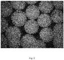
- FIG. 1 is a photo micrograph of the retroreflective composite of Example 2; and FIG. 2 is a photo micrograph of the retroreflective composite of Example 4, each figure showing a complete array of a single layer of peripheral beads on the spherical substrate.
- This coating step is repeated building up the interphase layer to about 100-200 ⁇ , a dimension selected to form an interphase layer or bonding layer of a thickness that can reveal a significant portion of the later added peripheral bead.
- the fused glass interphase contains the aligned mica plates, a residue from the coating.
- the sintered glass bead with the interphase layer is returned to the rotary reaction vessel and is coated with an amount in grams of interfacial modifier and the rotary reaction vessel is rotated at about six revolutions per second until the interfacial modifier forms a uniform coating on the interphase layer.
- To the interphase layer is introduced an amount in grams of a peripheral bead having a diameter of about 20 to 200 ⁇ and a refractive index of 1.8 to 2.4.
- the reaction vessel is rotated at approximately six revolution per second until the glass bead forms a substantially uniform single layer substantially completely covering the interfacially modified interphase layer.
- the interfacial modifier adheres the microsphere to the interphase layer and forms a mechanically stable bead layer.
- the contents of the reaction vessel were transferred to a crucible and sintered at approximately the same sintering profile beginning at 20 °C ramping rapidly up to 800 to 900 °C for about 20 minutes causing the micro-spherical glass bead to be fused into the interphase layer such that at least 40% of the microsphere is free of the interphase layer providing an optical retro reflective component.
- interfacial modifier initially adheres the bead to the interfacial modifier but as the combination is sintered, the microsphere slowly becomes embedded into and partially surrounded by the melt interphase layer to a degree such that at a functional amount of the microsphere is revealed above the fused surface for optical purposes.
- Tables 2-5 Exemplary information Example 1 2.0 mm.
- Example 3 1.5 mm 1.9 RI. Mica/TiO2 Sinter #1 Sinter #2 Sinter #3 Final Sinter Component Mass (g) IM Load (pph) Component Mass (g) IM Load (pph) Component Mass (g) IM Load (pph) Component Mass (g) IM Glass 1.5mm 300 0.66 Sinter #1 Product 300 1 Sinter #2 Product 300 1 Sinter #3 Product 5 0.15 70 ⁇ Glass 30 0 10 ⁇ 5 ⁇ glass 30 0 10 ⁇ 5 ⁇ glass 30 0 10 ⁇ 5 ⁇ glass 30 0 10 ⁇ 5 ⁇ glass yellow 0.05 0 Mica 2 0 Mica 2 0 Mica 2 0 Mica 2 0 TiO 2 5 0 TiO 2 5 0 TiO 2 5 0 Retro Bead 1.9 RI 2 0 Sinter Cycle °C Time (min.) Sinter Cycle °C Time (min.) Sinter Cycle °C Time (min.) 730 30, pre heated 740 30, pre heated 740 30, pre heated 875 30, pre heated
- TiO 2 titanium dioxide
- IM interfacial modifier
- a rotary blender heated (heat to 105°C).
- the contents were stirred and heated until uniform and the contents were removed from the blender and pushed through a 100-mesh screen using a rubber spatula to break up any agglomerates leaving only IM coated TiO 2 (pigment).
- Glass beads (particle size D50 ⁇ 9 ⁇ with a mean of 11 ⁇ ) were combined with 5.0 pph of interfacial modifier (IM) using a heated (heat to 105°C) and stirred rotary reaction vessel until the glass beads were uniformly coated.
- the IM coated beads were removed from the rotary reaction vessel and pushed through a 100-mesh screen using a rubber spatula to break up any agglomerates leaving only coated beads.
- the IM/TiO 2 (pigment)/glass coating composition was formed by combining a mass of the interfacially modified titanium dioxide and interfacially modified 70 ⁇ glass beads at a mass ratio of 1:TiO 2 : spherical glass particulate in a suitable sized disposable tri-pour beaker. Mix the combined IM coated fine spherical glass powder and IM coated titanium dioxide thoroughly by hand with a stainless-steel spatula. This mixture formed the bead coating composition IM/glass composition.
- the following retroreflective composite bead was made. About 362 grams of large core bead, having a particle size of 600-800 ⁇ , was combined with IM at a ratio of about 0.5 pph. Separately 36 grams of the glass particulate, having a particle size of 5-7 ⁇ was combined with about 5 parts by weight of IM. Also, separately about 4 grams of the TiO 2 (pigment) was combined with about 5 pph IM. Those three materials were combined, and as described above, and sintered with a sinter period of 60 minutes at 650°C.
- the following retroreflective composite beads was made. About 200 grams of Glass 2 mm core bead, having a particle size of 600-800 ⁇ , was combined with IM at a ratio of about 1 pph of glass bead. Separately 25 grams of the glass particulate, having a particle size of 5-7 ⁇ was combined with about 5 parts by weight of IM. Also, separately about 3.2 grams of the TiO 2 (pigment) was left uncoated. Those three materials were combined, and as described above, and sintered with a sinter period of 60 minutes at 650 °C.
- the following retroreflective composite bead was made. About 360 grams of glass 2 mm core bead, having a particle size of 600-800 ⁇ , was combined with IM at a ratio of about 0.5 pph glass. Separately 36 grams of the glass bead particulate, having a particle size of 5-7 ⁇ was combined with about 5 parts by weight of IM. Also, separately about 4 grams of the TiO2 (pigment) was coated with 5 pph IM. Those three materials were combined, and as described above, and sintered with a sinter period of 60 minutes at 650°C.
- the following retroreflective composite bead was made. About 360 grams of glass 2 mm core bead, having a particle size of 600-800 ⁇ , was combined with IM at a ratio of about 0.5 pph. Separately 34 grams of the glass particulate, having a particle size of 5-7 ⁇ was combined with about 5 parts by weight of IM. Also, separately about 6 grams of the TiO2 (pigment) was coated with 5 pph IM. Those three materials were combined, and as described above, and sintered with a sinter period of 60 minutes at 650 °C.
- the retroreflective bead object performance characteristics can be measured in several ways: retro reflectivity of the bead by itself; retroreflectivity of the bead in a painted highway marking line; color of the line after addition of the retroreflective beads as compared to color without retroreflective beads; retroreflectivity of the line after wear testing with traffic; and color of the line with retroreflective beads after wear testing.
- Retroreflective glass bead durability can be further evaluated using a "shake test" designed to qualitatively compare batches of retroreflective glass bead object one to another and to simulate severe abrasion of retroreflective glass bead object.
- a shake test designed to qualitatively compare batches of retroreflective glass bead object one to another and to simulate severe abrasion of retroreflective glass bead object.
- fifty (50) grams of retroreflective glass bead object will be combined in a steel one pint can with one hundred (100) grams of grinding media, namely one-half inch by one-half inch Burundum ceramic media available from Fisher Scientific. The can will be then shaken vigorously for 60 seconds. After shaking, a 20-mesh screen is used to sieve out any loose, very fine generally spherical glass members. Material that passes through the 20-mesh screen, and hence is smaller than 20 mesh, will be then weighed, and recorded as a percentage of the retroreflective glass bead media.
- a field test to expose a finished stripe was conducted, consisting of paint having retroreflective glass bead and standard highway marking glass beads also applied thereto, is used to simulate exposure to severe continuous high-speed rubber wheel traffic.
- a sample stripe is be prepared on concrete with epoxy paint. Retroreflective glass bead object and standard highway marking beads will be applied to the epoxy paint stripe. Retroreflectivity is measured, and color determined for the stripe, using the ASTM procedures and equipment described above, both before and after the test.
- the retroreflective beads may be used in tapes, films, coatings, or paints.
- the retroreflective materials can be applied to a highway surface by trucks dropping exact amounts of the retroreflective composites on freshly applied highway and colored marking lines.
- the lines utilize two component curing/reactive chemistries such as epoxy, epoxy hybrids, polyurethanes and polyureas and are often pigmented either yellow or light.
- the embodiments are not limited by the base color of the surface.
- the retroreflective beads When the retroreflective beads are applied, the line is flooded with the retroreflective beads that embed into the surface of the line. The line is ready for traffic in two to ten minutes, depending on the specific line chemistry used.
- the retroreflective bead article may be mixed with small, bare retroreflective beads known in the art.
- the bead has the peripheral bead array affixed to the surface of the central bead.
- a retroreflective composite can be made by fusing a coating or an array of peripheral beads on the surface a core bead. These are usable in standard retroreflective uses. For example, for highway marking having high retroreflectivity both when initially installed and over the bead lifetime, allowing vehicle drivers to see highway marking lines at night and in adverse conditions during nighttime. When installed the retroreflective beads essentially retroreflect the base color of the highway marking material in which the retroreflective beads are embedded.
- a kit comprising a plurality of individually packaged units of the heat bonded, retroreflective bead objects to be administered during application of the highway marking strip or during application to other surfaces requiring retroreflectivity are supplied with instructions for use.
- the individually packaged units may comprise heat bonded retroreflective beads all of one size.
- individually packaged units may comprise heat bonded retroreflective bead in mixed sizes.
- individually packaged units may comprise heat bonded retroreflective beads mixed with beads that are not heat bonded retroreflective beads.
- a further embodiment is to apply the retroreflective beads to a highway by trucks dropping exact amounts of the retroreflective beads on freshly applied thermoplastic or latex colored paint.
- the claims may suitably comprise, consist of, or consist essentially of, or be substantially free or free of any of the disclosed or recited elements.
- the claimed technology is illustratively disclosed herein can also be suitably practiced in the absence of any element which is not specifically disclosed herein.
- the various embodiments described above are provided by way of illustration only and should not be construed to limit the claims attached hereto. Various modifications and changes may be made without following the example embodiments and applications illustrated and described herein, and without departing from the true spirit and scope of the following claims.
Landscapes
- Chemical & Material Sciences (AREA)
- Engineering & Computer Science (AREA)
- Life Sciences & Earth Sciences (AREA)
- Geochemistry & Mineralogy (AREA)
- Organic Chemistry (AREA)
- Materials Engineering (AREA)
- Chemical Kinetics & Catalysis (AREA)
- General Chemical & Material Sciences (AREA)
- Physics & Mathematics (AREA)
- Optics & Photonics (AREA)
- General Physics & Mathematics (AREA)
- Inorganic Chemistry (AREA)
- General Life Sciences & Earth Sciences (AREA)
- Health & Medical Sciences (AREA)
- Mechanical Engineering (AREA)
- Ophthalmology & Optometry (AREA)
- Manufacturing & Machinery (AREA)
- Composite Materials (AREA)
- Ceramic Engineering (AREA)
- Architecture (AREA)
- Civil Engineering (AREA)
- Structural Engineering (AREA)
- Optical Elements Other Than Lenses (AREA)
- Laminated Bodies (AREA)
Applications Claiming Priority (2)
| Application Number | Priority Date | Filing Date | Title |
|---|---|---|---|
| US202163136603P | 2021-01-12 | 2021-01-12 | |
| US17/498,533 US12196987B2 (en) | 2021-01-12 | 2021-10-11 | Retroreflective composite reflective microspheres and reflective inorganic material |
Publications (3)
| Publication Number | Publication Date |
|---|---|
| EP4027178A1 true EP4027178A1 (de) | 2022-07-13 |
| EP4027178C0 EP4027178C0 (de) | 2024-10-09 |
| EP4027178B1 EP4027178B1 (de) | 2024-10-09 |
Family
ID=79317114
Family Applications (1)
| Application Number | Title | Priority Date | Filing Date |
|---|---|---|---|
| EP22151070.4A Active EP4027178B1 (de) | 2021-01-12 | 2022-01-11 | Retroreflektierende zusammengesetzte reflektierende mikrokugeln und reflektierendes anorganisches material |
Country Status (3)
| Country | Link |
|---|---|
| US (1) | US12196987B2 (de) |
| EP (1) | EP4027178B1 (de) |
| CA (1) | CA3145365A1 (de) |
Cited By (1)
| Publication number | Priority date | Publication date | Assignee | Title |
|---|---|---|---|---|
| EP4163261A1 (de) * | 2021-10-11 | 2023-04-12 | Tundra Composites, LLC | Schmelzschicht und kern |
Citations (16)
| Publication number | Priority date | Publication date | Assignee | Title |
|---|---|---|---|---|
| US5670209A (en) | 1995-04-24 | 1997-09-23 | Brite-Line Technologies, Inc. | High brightness durable retro-reflecting microspheres and method of making the same |
| US5750191A (en) | 1994-05-20 | 1998-05-12 | Minnesota Mining And Manufacturing Company | Retroreflective elements |
| US5774265A (en) | 1996-02-05 | 1998-06-30 | Minnesota Mining And Manufacturing Company | Durable retroreflective elements |
| US5942280A (en) | 1997-09-16 | 1999-08-24 | 3M Innovative Properties Company | Method of making retroreflective elements |
| US20050100709A1 (en) | 2003-11-06 | 2005-05-12 | 3M Innovative Properties Company | Retroreflective elements comprising a bonded resin core and pavement markings |
| US20050158461A1 (en) | 2004-01-21 | 2005-07-21 | 3M Innovative Properties Company | Methods of making reflective elements |
| US7513941B2 (en) | 2005-11-14 | 2009-04-07 | 3M Innovative Properties Company | Pavement marking, reflective elements, and methods of making micospheres |
| KR100973980B1 (ko) * | 2010-02-02 | 2010-08-05 | 정영호 | 내구성 및 우천시 재귀반사도가 우수한 재귀반사체의 제조방법 및 이로 제조된 재귀반사체 |
| US20110170193A1 (en) | 2007-12-21 | 2011-07-14 | Budd Kenton D | Retroreflective articles in the form of garments, fibers and filaments |
| US8292539B2 (en) | 2007-04-10 | 2012-10-23 | Stoncor Group, Inc. | Agglomerated retroreflective beads for highway marking and methods for fabrication and use thereof |
| US8591045B2 (en) | 2009-08-21 | 2013-11-26 | 3M Innovative Properties Company | Pavement markings, reflective elements, and methods of making microspheres |
| US8591044B2 (en) | 2009-08-21 | 2013-11-26 | 3M Innovative Properties Company | Pavement markings, reflective elements, and methods of making microspheres |
| US20170242165A1 (en) | 2014-08-08 | 2017-08-24 | 3Minnovative Properties Company | Retroreflective elements including particles |
| US20180291175A1 (en) | 2015-09-11 | 2018-10-11 | 3M Innovative Properties Company | Durable retroreflective elements with a blend of beads |
| US20200115289A1 (en) * | 2017-06-02 | 2020-04-16 | Tundra Composites, LLC | Surface Modified Particulate In Sintered Products |
| WO2020087090A1 (en) * | 2018-10-26 | 2020-04-30 | Tundra Composites, LLC | Polymer compatible heat fused retroreflective bead |
Family Cites Families (64)
| Publication number | Priority date | Publication date | Assignee | Title |
|---|---|---|---|---|
| US2268537A (en) | 1939-05-19 | 1941-12-30 | Shuger Leroy | Road marker |
| US2326634A (en) | 1941-12-26 | 1943-08-10 | Minnesota Mining & Mfg | Reflex light reflector |
| US2379702A (en) | 1943-01-23 | 1945-07-03 | Minnesota Mining & Mfg | Reflex light reflector |
| US2610922A (en) | 1950-03-14 | 1952-09-16 | Minnesota Mining & Mfg | Reflex-reflector lens elements |
| US2687968A (en) | 1950-07-26 | 1954-08-31 | Minnesota Mining & Mfg | Reflex-reflector lens elements |
| US2853393A (en) | 1951-07-05 | 1958-09-23 | Minnesota Mining & Mfg | High-index glass elements |
| DE1065580B (de) | 1953-08-12 | 1959-09-17 | Minnesota Mining and Manufacturing Company, Saint Paul, Minn. (V. St. A.) | Durchsichtiges Glaselement mit einer Stärke von nicht mehr 2 mm |
| US2842446A (en) | 1954-12-27 | 1958-07-08 | Minnesota Mining & Mfg | High-index glass elements |
| US2963378A (en) | 1955-04-25 | 1960-12-06 | Minnesota Mining & Mfg | Ass beads hemispherically reflectorled with metallic coating and compositions thereof |
| US2883347A (en) | 1955-09-13 | 1959-04-21 | Bell Telephone Labor Inc | Formation of expanded silica spheres |
| US3365315A (en) | 1963-08-23 | 1968-01-23 | Minnesota Mining & Mfg | Glass bubbles prepared by reheating solid glass partiles |
| US4697407A (en) | 1980-03-24 | 1987-10-06 | Minnesota Mining And Manufacturing Company | Retroreflective fiber and method of making same |
| US4336092A (en) | 1980-03-24 | 1982-06-22 | Allan Wasserman | Retroreflective fiber and method of making same |
| US4983458A (en) | 1984-09-21 | 1991-01-08 | Potters Industries, Inc. | Reflective particles |
| US5057552A (en) | 1987-03-11 | 1991-10-15 | The Dow Chemical Company | Flexible thermoplastic epoxy resin and coatings prepared therefrom |
| US5169558A (en) | 1989-07-21 | 1992-12-08 | Fox Valley Systems, Inc. | Two-part aerosol composition for increasing the light reflectivity of an object |
| GB9312482D0 (en) | 1993-06-17 | 1993-08-04 | Rohm & Haas France | Improvements relating to traffic paints |
| JPH09506301A (ja) | 1993-11-17 | 1997-06-24 | リフレクティヴ テクノロジー インダストリーズ リミテッド | 逆反射性材料 |
| CA2187929A1 (en) | 1994-05-02 | 1995-11-09 | Susan K. Nestegard | Retroreflective polymer coated flexible fabric material and method of manufacture |
| EP0711814B1 (de) | 1994-10-21 | 2001-04-11 | Hitachi Maxell Ltd. | Fluoreszierende Markierungszusammensetzung und erhaltene Markierung |
| JPH10512611A (ja) | 1995-01-18 | 1998-12-02 | ザ ダウ ケミカル カンパニー | 速硬性水性塗料組成物およびペイント |
| EP0856088B1 (de) | 1995-10-18 | 2000-12-13 | Minnesota Mining And Manufacturing Company | Anpassungsfähiger magnetischer gegenstand für unter verkehr tragende oberflächen |
| CA2177634C (en) | 1996-01-17 | 2000-02-22 | George Mcilwraith | Reflective materials for manufacture of reflective lighting elements including parabolic louvers and the like |
| FR2745293A1 (fr) | 1996-02-26 | 1997-08-29 | Rohm & Haas France | Peinture de signalisation routiere, procede d'acceleration du sechage de ladite peinture et utilisation de particules d'un compose polymere ou mineral solide |
| US5948833A (en) | 1996-06-04 | 1999-09-07 | Rohm And Haas Company | Method of reducing yellowing of water-borne road marking paints and composition used therein |
| US6132132A (en) | 1997-02-26 | 2000-10-17 | Rohm And Haas Company | Water-based road marking paint |
| JP3993269B2 (ja) | 1997-04-18 | 2007-10-17 | スリーエム カンパニー | 透明ビーズおよびその製造方法 |
| WO1998047830A1 (en) | 1997-04-18 | 1998-10-29 | Minnesota Mining And Manufacturing Company | Transparent beads and their production method |
| US6194486B1 (en) | 1997-05-28 | 2001-02-27 | Trw Inc. | Enhanced paint for microwave/millimeter wave radiometric detection applications and method of road marker detection |
| ATE320458T1 (de) | 1997-06-13 | 2006-04-15 | Minnesota Mining & Mfg | Flüssige fahrbahnmarkierungszusammensetzungen |
| BR9810030A (pt) | 1997-06-13 | 2000-09-12 | Eastman Chem Co | Composições de balizamento de tráfego adesivo de fusão quente, amarelas. |
| US5928761A (en) | 1997-07-16 | 1999-07-27 | Minnesota Mining And Manufacturing Company | Retroreflective black pavement marking articles |
| JP4031562B2 (ja) * | 1997-11-05 | 2008-01-09 | 日本ペイント株式会社 | 光輝性塗料組成物および光輝性複合塗膜形成方法 |
| EP0950763A1 (de) | 1998-04-16 | 1999-10-20 | Rohm And Haas Company | Abriebfeste Verkehrsmarkierung und wässrige Strassenmarkierungsfarbe |
| US6365262B1 (en) | 1998-10-20 | 2002-04-02 | 3M Innovative Properties Company | Pavement marking articles having enhanced retroreflectivity under dry or wet conditions and method for making same |
| US6245700B1 (en) | 1999-07-27 | 2001-06-12 | 3M Innovative Properties Company | Transparent microspheres |
| US6689824B2 (en) | 2000-02-18 | 2004-02-10 | Rohm And Haas Company | Prepaints and method of preparing road-marking paints from prepaints |
| JP4028155B2 (ja) | 2000-04-11 | 2007-12-26 | 日本カーバイド工業株式会社 | 蛍光性再帰反射シート |
| US6632508B1 (en) | 2000-10-27 | 2003-10-14 | 3M Innovative Properties Company | Optical elements comprising a polyfluoropolyether surface treatment |
| AU785048B2 (en) | 2001-03-21 | 2006-09-07 | Rohm And Haas Company | Method for preparing storage-stable fast-drying multi-component aqueous coating compositions and coatings derived therefrom |
| JP5036940B2 (ja) | 2001-09-10 | 2012-09-26 | ローム アンド ハース カンパニー | 路面標示用水性塗料組成物 |
| US6734227B2 (en) | 2001-09-24 | 2004-05-11 | 3M Innovative Properties Company | Optical elements comprising a fluoropolymer surface treatment |
| US7169831B2 (en) | 2001-09-27 | 2007-01-30 | 3M Innovative Properties Company | Pavement marking composition comprising ceramic fibers |
| US20030090800A1 (en) | 2001-11-01 | 2003-05-15 | 3M Innovative Properties Company | Reflective elements comprising reinforcement particles dispersed within a core |
| US7364314B2 (en) | 2002-05-15 | 2008-04-29 | Reflexite Corporation | Optical structures |
| WO2004017104A2 (en) | 2002-08-15 | 2004-02-26 | Light Bead Llc | Retroreflective aerosol coating composition and methods of making and using thereof |
| US20050015846A1 (en) | 2003-06-26 | 2005-01-27 | Kimberly-Clark Worldwide, Inc. | Polyvinyl chloride article having improved durability |
| JP4145261B2 (ja) | 2003-08-04 | 2008-09-03 | ローム アンド ハース カンパニー | 水性トラフィックペイントおよび塗布方法 |
| JP4681949B2 (ja) * | 2004-05-27 | 2011-05-11 | 積水樹脂株式会社 | 高視認性道路用標示体 |
| US7342056B2 (en) | 2004-06-17 | 2008-03-11 | 3M Innovative Properties Company | Pavement marking comprising modified isocyanate |
| US7506523B2 (en) | 2004-11-08 | 2009-03-24 | Beck Warren R | Method of making hollow inorganic microspheres, and products made thereby |
| US8202614B2 (en) | 2006-08-09 | 2012-06-19 | Luna Innovations Incorporated | Additive particles having superhydrophobic characteristics and coatings and methods of making and using the same |
| US9207373B2 (en) | 2007-04-10 | 2015-12-08 | Stoncor Group, Inc. | Methods for fabrication and highway marking usage of agglomerated retroreflective beads |
| US20090025872A1 (en) | 2007-07-26 | 2009-01-29 | Nilsen Robert B | Method of making and using retroreflective fibers |
| US8033671B1 (en) | 2007-08-10 | 2011-10-11 | Technology Solutions & Invention Llc | Retroreflective structures having a helical geometry |
| CN101946192B (zh) * | 2007-12-21 | 2012-09-05 | 3M创新有限公司 | 回射制品以及包括球芯和两个同心光学干涉层的回射元件 |
| BRPI0910033A2 (pt) | 2008-03-28 | 2015-12-29 | 3M Innovative Properties Co | processo para a modificação de superfícies de partículas |
| US7900474B2 (en) | 2008-08-14 | 2011-03-08 | Beck Warren R | Hollow glass microspheres comprising selenium oxide and method of making thereof |
| US20100272962A1 (en) | 2009-04-22 | 2010-10-28 | Potters Industries Inc. | Reflective substrate surface system, reflective assembly, and methods of improving the visibility of a substrate surface |
| US10315385B2 (en) | 2011-08-05 | 2019-06-11 | Certainteed Corporation | System, method and apparatus for increasing surface solar reflectance of roofing |
| US9238725B2 (en) * | 2011-11-04 | 2016-01-19 | Nihon Tokushu Toryo Co., Ltd. | Infrared reflective film, infrared reflective paint and infrared reflective body |
| US20160209559A1 (en) | 2015-01-20 | 2016-07-21 | Brite-Line Technologies, Llc | Pavement marking tape incorporating advanced materials for improved visibility |
| US11353640B2 (en) | 2015-09-11 | 2022-06-07 | 3M Innovative Properties Company | Durable retroreflective elements with an ionic copolymer core |
| US11467324B2 (en) * | 2018-10-26 | 2022-10-11 | Tundra Composits, LLC | Complex retroreflective bead |
-
2021
- 2021-10-11 US US17/498,533 patent/US12196987B2/en active Active
-
2022
- 2022-01-11 CA CA3145365A patent/CA3145365A1/en active Pending
- 2022-01-11 EP EP22151070.4A patent/EP4027178B1/de active Active
Patent Citations (16)
| Publication number | Priority date | Publication date | Assignee | Title |
|---|---|---|---|---|
| US5750191A (en) | 1994-05-20 | 1998-05-12 | Minnesota Mining And Manufacturing Company | Retroreflective elements |
| US5670209A (en) | 1995-04-24 | 1997-09-23 | Brite-Line Technologies, Inc. | High brightness durable retro-reflecting microspheres and method of making the same |
| US5774265A (en) | 1996-02-05 | 1998-06-30 | Minnesota Mining And Manufacturing Company | Durable retroreflective elements |
| US5942280A (en) | 1997-09-16 | 1999-08-24 | 3M Innovative Properties Company | Method of making retroreflective elements |
| US20050100709A1 (en) | 2003-11-06 | 2005-05-12 | 3M Innovative Properties Company | Retroreflective elements comprising a bonded resin core and pavement markings |
| US20050158461A1 (en) | 2004-01-21 | 2005-07-21 | 3M Innovative Properties Company | Methods of making reflective elements |
| US7513941B2 (en) | 2005-11-14 | 2009-04-07 | 3M Innovative Properties Company | Pavement marking, reflective elements, and methods of making micospheres |
| US8292539B2 (en) | 2007-04-10 | 2012-10-23 | Stoncor Group, Inc. | Agglomerated retroreflective beads for highway marking and methods for fabrication and use thereof |
| US20110170193A1 (en) | 2007-12-21 | 2011-07-14 | Budd Kenton D | Retroreflective articles in the form of garments, fibers and filaments |
| US8591045B2 (en) | 2009-08-21 | 2013-11-26 | 3M Innovative Properties Company | Pavement markings, reflective elements, and methods of making microspheres |
| US8591044B2 (en) | 2009-08-21 | 2013-11-26 | 3M Innovative Properties Company | Pavement markings, reflective elements, and methods of making microspheres |
| KR100973980B1 (ko) * | 2010-02-02 | 2010-08-05 | 정영호 | 내구성 및 우천시 재귀반사도가 우수한 재귀반사체의 제조방법 및 이로 제조된 재귀반사체 |
| US20170242165A1 (en) | 2014-08-08 | 2017-08-24 | 3Minnovative Properties Company | Retroreflective elements including particles |
| US20180291175A1 (en) | 2015-09-11 | 2018-10-11 | 3M Innovative Properties Company | Durable retroreflective elements with a blend of beads |
| US20200115289A1 (en) * | 2017-06-02 | 2020-04-16 | Tundra Composites, LLC | Surface Modified Particulate In Sintered Products |
| WO2020087090A1 (en) * | 2018-10-26 | 2020-04-30 | Tundra Composites, LLC | Polymer compatible heat fused retroreflective bead |
Cited By (2)
| Publication number | Priority date | Publication date | Assignee | Title |
|---|---|---|---|---|
| EP4163261A1 (de) * | 2021-10-11 | 2023-04-12 | Tundra Composites, LLC | Schmelzschicht und kern |
| US12617712B2 (en) | 2021-10-11 | 2026-05-05 | Tundra COmpoistes, LLC | Fused layer and core |
Also Published As
| Publication number | Publication date |
|---|---|
| US12196987B2 (en) | 2025-01-14 |
| EP4027178C0 (de) | 2024-10-09 |
| CA3145365A1 (en) | 2022-07-12 |
| US20220221628A1 (en) | 2022-07-14 |
| EP4027178B1 (de) | 2024-10-09 |
Similar Documents
| Publication | Publication Date | Title |
|---|---|---|
| CA2243999C (en) | Durable retroreflective elements | |
| US5942280A (en) | Method of making retroreflective elements | |
| US4564556A (en) | Transparent non-vitreous ceramic particulate | |
| CN101304954B (zh) | 道路标记、反射元件及制造微球体的方法 | |
| US11860389B2 (en) | Complex retroreflective bead | |
| US5917652A (en) | Durable retroreflective elements | |
| CN101679108B (zh) | 具有含氧化镧和氧化铝以及氧化锆、二氧化钛或它们的混合物的微球的道路标记和反射元件 | |
| EP2844706B1 (de) | Bedachungskoerner mit hoher sonnenreflexion und verwendung von komponenten mit niedriger absorption | |
| EP2467342B1 (de) | Strassenmarkierungen, reflektierende elemente und verfahren zur herstellung von mikrokügelchen | |
| CN101614835B (zh) | 一种逆反射结构体及其制造方法 | |
| EP2467341A1 (de) | Strassenmarkierungen, reflektierende elemente und verfahren zur herstellung von mikrokügelchen | |
| EP4027178B1 (de) | Retroreflektierende zusammengesetzte reflektierende mikrokugeln und reflektierendes anorganisches material | |
| TWI680104B (zh) | 近紅外線吸收微粒子分散液及其製造方法 | |
| JP2001048586A (ja) | 光反射ガラスビーズ及びその製造方法 | |
| JPH11503993A (ja) | 耐酸性ガラス | |
| KR100973980B1 (ko) | 내구성 및 우천시 재귀반사도가 우수한 재귀반사체의 제조방법 및 이로 제조된 재귀반사체 | |
| WO2003038191A2 (en) | Reflective elements comprising reinforcement particles dispersed within a core | |
| US8172935B2 (en) | Special effect pigments | |
| EP3914941B1 (de) | Polymerkompatibler wärmefixierter rückstrahlender wulst | |
| US12617712B2 (en) | Fused layer and core | |
| JP2007505962A (ja) | 効果顔料が添加された粉末状の被覆材料、その製造方法及びその使用 | |
| MXPA00002621A (en) | Method of making retroreflective elements |
Legal Events
| Date | Code | Title | Description |
|---|---|---|---|
| PUAI | Public reference made under article 153(3) epc to a published international application that has entered the european phase |
Free format text: ORIGINAL CODE: 0009012 |
|
| STAA | Information on the status of an ep patent application or granted ep patent |
Free format text: STATUS: THE APPLICATION HAS BEEN PUBLISHED |
|
| AK | Designated contracting states |
Kind code of ref document: A1 Designated state(s): AL AT BE BG CH CY CZ DE DK EE ES FI FR GB GR HR HU IE IS IT LI LT LU LV MC MK MT NL NO PL PT RO RS SE SI SK SM TR |
|
| STAA | Information on the status of an ep patent application or granted ep patent |
Free format text: STATUS: REQUEST FOR EXAMINATION WAS MADE |
|
| 17P | Request for examination filed |
Effective date: 20230113 |
|
| RBV | Designated contracting states (corrected) |
Designated state(s): AL AT BE BG CH CY CZ DE DK EE ES FI FR GB GR HR HU IE IS IT LI LT LU LV MC MK MT NL NO PL PT RO RS SE SI SK SM TR |
|
| GRAP | Despatch of communication of intention to grant a patent |
Free format text: ORIGINAL CODE: EPIDOSNIGR1 |
|
| STAA | Information on the status of an ep patent application or granted ep patent |
Free format text: STATUS: GRANT OF PATENT IS INTENDED |
|
| INTG | Intention to grant announced |
Effective date: 20240503 |
|
| GRAS | Grant fee paid |
Free format text: ORIGINAL CODE: EPIDOSNIGR3 |
|
| GRAA | (expected) grant |
Free format text: ORIGINAL CODE: 0009210 |
|
| STAA | Information on the status of an ep patent application or granted ep patent |
Free format text: STATUS: THE PATENT HAS BEEN GRANTED |
|
| AK | Designated contracting states |
Kind code of ref document: B1 Designated state(s): AL AT BE BG CH CY CZ DE DK EE ES FI FR GB GR HR HU IE IS IT LI LT LU LV MC MK MT NL NO PL PT RO RS SE SI SK SM TR |
|
| REG | Reference to a national code |
Ref country code: CH Ref legal event code: EP |
|
| REG | Reference to a national code |
Ref country code: DE Ref legal event code: R096 Ref document number: 602022006553 Country of ref document: DE |
|
| REG | Reference to a national code |
Ref country code: IE Ref legal event code: FG4D |
|
| U01 | Request for unitary effect filed |
Effective date: 20241009 |
|
| U07 | Unitary effect registered |
Designated state(s): AT BE BG DE DK EE FI FR IT LT LU LV MT NL PT RO SE SI Effective date: 20241015 |
|
| U20 | Renewal fee for the european patent with unitary effect paid |
Year of fee payment: 4 Effective date: 20250127 |
|
| PG25 | Lapsed in a contracting state [announced via postgrant information from national office to epo] |
Ref country code: HR Free format text: LAPSE BECAUSE OF FAILURE TO SUBMIT A TRANSLATION OF THE DESCRIPTION OR TO PAY THE FEE WITHIN THE PRESCRIBED TIME-LIMIT Effective date: 20241009 Ref country code: IS Free format text: LAPSE BECAUSE OF FAILURE TO SUBMIT A TRANSLATION OF THE DESCRIPTION OR TO PAY THE FEE WITHIN THE PRESCRIBED TIME-LIMIT Effective date: 20250209 |
|
| PG25 | Lapsed in a contracting state [announced via postgrant information from national office to epo] |
Ref country code: ES Free format text: LAPSE BECAUSE OF FAILURE TO SUBMIT A TRANSLATION OF THE DESCRIPTION OR TO PAY THE FEE WITHIN THE PRESCRIBED TIME-LIMIT Effective date: 20241009 |
|
| PG25 | Lapsed in a contracting state [announced via postgrant information from national office to epo] |
Ref country code: NO Free format text: LAPSE BECAUSE OF FAILURE TO SUBMIT A TRANSLATION OF THE DESCRIPTION OR TO PAY THE FEE WITHIN THE PRESCRIBED TIME-LIMIT Effective date: 20250109 |
|
| PG25 | Lapsed in a contracting state [announced via postgrant information from national office to epo] |
Ref country code: GR Free format text: LAPSE BECAUSE OF FAILURE TO SUBMIT A TRANSLATION OF THE DESCRIPTION OR TO PAY THE FEE WITHIN THE PRESCRIBED TIME-LIMIT Effective date: 20250110 |
|
| PG25 | Lapsed in a contracting state [announced via postgrant information from national office to epo] |
Ref country code: PL Free format text: LAPSE BECAUSE OF FAILURE TO SUBMIT A TRANSLATION OF THE DESCRIPTION OR TO PAY THE FEE WITHIN THE PRESCRIBED TIME-LIMIT Effective date: 20241009 |
|
| PG25 | Lapsed in a contracting state [announced via postgrant information from national office to epo] |
Ref country code: RS Free format text: LAPSE BECAUSE OF FAILURE TO SUBMIT A TRANSLATION OF THE DESCRIPTION OR TO PAY THE FEE WITHIN THE PRESCRIBED TIME-LIMIT Effective date: 20250109 |
|
| PG25 | Lapsed in a contracting state [announced via postgrant information from national office to epo] |
Ref country code: SM Free format text: LAPSE BECAUSE OF FAILURE TO SUBMIT A TRANSLATION OF THE DESCRIPTION OR TO PAY THE FEE WITHIN THE PRESCRIBED TIME-LIMIT Effective date: 20241009 |
|
| PG25 | Lapsed in a contracting state [announced via postgrant information from national office to epo] |
Ref country code: SK Free format text: LAPSE BECAUSE OF FAILURE TO SUBMIT A TRANSLATION OF THE DESCRIPTION OR TO PAY THE FEE WITHIN THE PRESCRIBED TIME-LIMIT Effective date: 20241009 |
|
| PG25 | Lapsed in a contracting state [announced via postgrant information from national office to epo] |
Ref country code: CZ Free format text: LAPSE BECAUSE OF FAILURE TO SUBMIT A TRANSLATION OF THE DESCRIPTION OR TO PAY THE FEE WITHIN THE PRESCRIBED TIME-LIMIT Effective date: 20241009 |
|
| PLBE | No opposition filed within time limit |
Free format text: ORIGINAL CODE: 0009261 |
|
| STAA | Information on the status of an ep patent application or granted ep patent |
Free format text: STATUS: NO OPPOSITION FILED WITHIN TIME LIMIT |
|
| REG | Reference to a national code |
Ref country code: CH Ref legal event code: PL |
|
| PG25 | Lapsed in a contracting state [announced via postgrant information from national office to epo] |
Ref country code: MC Free format text: LAPSE BECAUSE OF FAILURE TO SUBMIT A TRANSLATION OF THE DESCRIPTION OR TO PAY THE FEE WITHIN THE PRESCRIBED TIME-LIMIT Effective date: 20241009 |
|
| 26N | No opposition filed |
Effective date: 20250710 |
|
| PG25 | Lapsed in a contracting state [announced via postgrant information from national office to epo] |
Ref country code: CH Free format text: LAPSE BECAUSE OF NON-PAYMENT OF DUE FEES Effective date: 20250131 |
|
| PG25 | Lapsed in a contracting state [announced via postgrant information from national office to epo] |
Ref country code: IE Free format text: LAPSE BECAUSE OF NON-PAYMENT OF DUE FEES Effective date: 20250111 |
|
| U20 | Renewal fee for the european patent with unitary effect paid |
Year of fee payment: 5 Effective date: 20260127 |