EP4028687B1 - Dispositif de recouvrement pour un appareil d'alimentation en barres d'une machine-outil - Google Patents
Dispositif de recouvrement pour un appareil d'alimentation en barres d'une machine-outil Download PDFInfo
- Publication number
- EP4028687B1 EP4028687B1 EP20786588.2A EP20786588A EP4028687B1 EP 4028687 B1 EP4028687 B1 EP 4028687B1 EP 20786588 A EP20786588 A EP 20786588A EP 4028687 B1 EP4028687 B1 EP 4028687B1
- Authority
- EP
- European Patent Office
- Prior art keywords
- covering device
- cover element
- longitudinal
- feeding
- hinge elements
- Prior art date
- Legal status (The legal status is an assumption and is not a legal conclusion. Google has not performed a legal analysis and makes no representation as to the accuracy of the status listed.)
- Active
Links
Images


Classifications
-
- B—PERFORMING OPERATIONS; TRANSPORTING
- B23—MACHINE TOOLS; METAL-WORKING NOT OTHERWISE PROVIDED FOR
- B23B—TURNING; BORING
- B23B13/00—Arrangements for automatically conveying or chucking or guiding stock
- B23B13/02—Arrangements for automatically conveying or chucking or guiding stock for turning-machines with a single working-spindle
- B23B13/025—Arrangements for automatically conveying or chucking or guiding stock for turning-machines with a single working-spindle with stock drum
-
- B—PERFORMING OPERATIONS; TRANSPORTING
- B23—MACHINE TOOLS; METAL-WORKING NOT OTHERWISE PROVIDED FOR
- B23B—TURNING; BORING
- B23B13/00—Arrangements for automatically conveying or chucking or guiding stock
- B23B13/12—Accessories, e.g. stops, grippers
- B23B13/126—Supports
-
- B—PERFORMING OPERATIONS; TRANSPORTING
- B23—MACHINE TOOLS; METAL-WORKING NOT OTHERWISE PROVIDED FOR
- B23B—TURNING; BORING
- B23B13/00—Arrangements for automatically conveying or chucking or guiding stock
- B23B13/12—Accessories, e.g. stops, grippers
- B23B13/128—Stock rest handling devices, e.g. ejectors
-
- F—MECHANICAL ENGINEERING; LIGHTING; HEATING; WEAPONS; BLASTING
- F16—ENGINEERING ELEMENTS AND UNITS; GENERAL MEASURES FOR PRODUCING AND MAINTAINING EFFECTIVE FUNCTIONING OF MACHINES OR INSTALLATIONS; THERMAL INSULATION IN GENERAL
- F16P—SAFETY DEVICES IN GENERAL; SAFETY DEVICES FOR PRESSES
- F16P1/00—Safety devices independent of the control and operation of any machine
- F16P1/02—Fixed screens or hoods
-
- E—FIXED CONSTRUCTIONS
- E05—LOCKS; KEYS; WINDOW OR DOOR FITTINGS; SAFES
- E05D—HINGES OR SUSPENSION DEVICES FOR DOORS, WINDOWS OR WINGS
- E05D15/00—Suspension arrangements for wings
- E05D15/48—Suspension arrangements for wings allowing alternative movements
- E05D15/50—Suspension arrangements for wings allowing alternative movements for opening at either of two opposite edges
- E05D15/507—Suspension arrangements for wings allowing alternative movements for opening at either of two opposite edges by detachment of the hinge from the wing or the frame
-
- E—FIXED CONSTRUCTIONS
- E05—LOCKS; KEYS; WINDOW OR DOOR FITTINGS; SAFES
- E05Y—INDEXING SCHEME ASSOCIATED WITH SUBCLASSES E05D AND E05F, RELATING TO CONSTRUCTION ELEMENTS, ELECTRIC CONTROL, POWER SUPPLY, POWER SIGNAL OR TRANSMISSION, USER INTERFACES, MOUNTING OR COUPLING, DETAILS, ACCESSORIES, AUXILIARY OPERATIONS NOT OTHERWISE PROVIDED FOR, APPLICATION THEREOF
- E05Y2999/00—Subject-matter not otherwise provided for in this subclass
Definitions
- the present invention relates to a covering device for an apparatus for automatic feeding to a machine tool, such as a lathe that can be of the single spindle or multispindle type.
- Apparatuses for feeding bars are known that are used for feeding and advancing the latter to machine tools like lathes.
- An apparatus for feeding bars for known type comprises a support frame, to which a drum is fitted that is provided with a plurality of guides for respective bars, a pusher suitable for pushing backwards and advancing one bar at a time to the machine tool, and other components.
- the aforesaid apparatus also known by the term feeding apparatus, has some limits set out above.
- a first drawback is the ineffective and poor covering and protection of the area around the feeding apparatus, which implies, in general, hazards for operators around the apparatus.
- waste chip elements from the bar being machined can be formed that, accelerated by the machine, are ejected at random around the machining area, with the risk of injuring the operator.
- Correct protection of the device not only reduces or eliminates possible risks to the health of the operators but is also used to protect the apparatus from possible mechanical damage. More precisely, it is necessary to prevent outer agents like chips, dirt, dust or liquids entering between the delicate mechanisms of the apparatus, in order to ensure as far as possible correct operation of the device, prevent the risk of malfunctions due to wear and prolong working life as long as possible.
- bar-feeding apparatuses are heavy and bulky systems, which are hardly adaptable in terms of positioning inside industrial premises and coupling with the machine tool to which the bars are fed. Further, once correct adjustment has been found following installation, known bar-feeding apparatuses cannot be moved because of the great weight, or anyway a movement thereof is very complex. It is thus necessary to make the design of apparatuses more easily adaptable to the machine tools used during the installation step and to the space available in the stores and which fitting is easier and less onerous.
- FR 1074458 in particular discloses an example of a covering device in accordance with the preamble of claim 1.
- An object of the present invention is to improve current bar feeding apparatuses, in particular the cover devices for feeding apparatuses.
- Another object of the present invention is to provide a covering device for a feeding apparatus for a machine tool that is simple and cheap to use, structurally simplified and able to operate effectively in any operating condition and solve the aforesaid limits of the prior art.
- Another object of the present invention is to improve the current protection and cover devices of bar-feeding apparatuses for feeding bars onto machine tools, in order to reduce as much as possible the risks to the health of the operators and damage to bar loading apparatuses.
- Another object of the present invention is to make the bar-feeding apparatus more adaptable and effective, in relation to the available use and space.
- the device according to the invention with a very simple structural configuration, enables great versatility and better adaptability and efficacy of the apparatus to be provided, by also increasing levels of safety for operators.
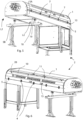
- a covering device 1 is shown fitted to an apparatus 2 for automatic feeding of bars to a machine tool, in particular to a lathe that can be of the single spindle type or multispindle type.
- the base structure of the covering device 1 consists of a support frame 3, consisting of a first longitudinal tubular element 12, a second longitudinal tubular element 13 and shaped transverse elements 14.
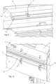
- the first longitudinal tubular element 12 is rotatably connectable, by first hinge elements 4, to a first portion of a frame structure 5 of the feeding apparatus 2, in particular on a first longitudinal side L1.
- the second longitudinal tubular element 13 is positioned at a second longitudinal side L2, parallel to and opposite the first side L1 of the frame structure 5.
- the first longitudinal tubular element 12 and the second longitudinal tubular element 13 are mutually parallel to and separated by a distance that is substantially equal to the width of the feeding apparatus 2.
- the second longitudinal tubular element 13, located at the second longitudinal side L2, is not connected to the frame structure 5 but, in particular, is shaped for resting on or being removed from, a second portion of said frame structure 5, opposite and parallel to the aforementioned first portion to which, on the other hand, the first longitudinal tubular element 12 hinged.
- the shaped transverse elements 14 complete the support frame 3, extending at short sides of the frame structure 5. More precisely, the shaped transverse elements 14 connect the ends of the first tubular element 12 to the respective ends of the second longitudinal tubular element 13.
- a cover element 6 comes to rest that is rotatably connected by second hinge elements 7 to the second tubular element 13 and thus to the support frame 3.
- the cover element 6 extends and is configured so as to cover completely above the volume defined in the apparatus 2 inside which a bar-feeding drum 9 and the remaining mechanical components are housed. The thus configured cover element 6 thus ensures complete protection of the operators and of the apparatus 2.
- first hinge elements 4 and the second hinge elements 7 are thus arranged on the respective longitudinal sides L1 and L2 opposite one another of the support frame 3. Owing to this configuration, it is possible to open the covering device 1 on both sides of said feeding apparatus 2. In other words, advantageously, it is possible to choose indifferently in a desired manner from which side to open the covering device 1 to access the components inside the feeding apparatus 2.
- the cover element 6 is provided with breaks that are suitably distributed and obtained in zones that are intended to be superimposed, in the closed position, on the corresponding first hinge elements 4, so that the cover element 6 can completely cover the first longitudinal tubular element 12, without the first hinge elements 4 being an obstacle to closing.
- the number of breaks depends on the length of the frame structure 5 and on the number of first hinge elements 4.
- the cover element 6 comprises respective movement handles 15 on both the longitudinal sides L1/L2, to permit raising and lowering thereof by an operator.
- One or more pneumatic or hydraulic pistons can be provided to facilitate and assist manual opening and closing of the device 1.
- the cover element 6 comprises one or more protection and insulation panels that can possibly consist of sheet metal, polycarbonate or another suitable material.
- the panels that make up the cover element 6 can comprise several layers, between which an acoustic insulating material is interposed.
- the cover element 6 can possibly comprise one or more protection and insulation panels made of transparent material or window zones 20 are provided to make the inside of the apparatus 2 visible; in this manner, an operator can inspect the status and operation of the apparatus 2 in safety without having to raise the cover element 6.
- a slit opening 8 is obtained that extends longitudinally, configured to enable bars to move from external auxiliary storage to the drum 9 of the feeding apparatus 2.
- a door 10 is hinged that is provided with handles 11, to facilitate the operations of opening and closing the door 10.
- the frame structure 5 of the apparatus 2 consists of an upper part 5A, which houses the previously disclosed drum 9 and covering device 1, and a base portion 5B that includes legs 16.
- the upper part 5A rests on said basement portion 5B by a coupling that includes relatively mobile rail elements 18 and wheels 19.
- the upper part 5A is adjustable, in a longitudinal direction, with respect to said basement portion 5B, to meet as well as possible every specific installation need and adapt to the available need and to the machine tool used.
- the legs 16 of the frame structure 5 are height-adjustable legs, each of which is made of two pieces 16A, 16B mutually fixed by means of screw elements 17 to enable the mutual fixing position thereof to be adjusted. In this manner, during assembly of the apparatus 2, before actual commissioning, it is possible to decide the actual height of the apparatus 2 owing to the adjustable legs 16 and the longitudinal position owing to the binary system 18 and wheels 19.
- the covering device 1 enables the objects disclosed above to be reached.
- a covering device 1 is provided that is very versatile and easy to use that is able ensure effective protection and at the same time make feeding bars to the apparatus easier and access to the inner parts from any side extremely easy.
- the apparatus is more easily adaptable both in terms of height and the longitudinal position.
- the possibility of raising the covering device 1 by acting on different zones thereof improves the versatility and adaptability and of the apparatus 2 to which it is fitted.
- the device 1 it is possible to configure and size the device 1 in a desired manner according to the applications to which it can be intended, and the materials used for making the device 1 can be chosen according to need provided that the need is compatible with the specific use for which they are intended.
Landscapes
- Engineering & Computer Science (AREA)
- Mechanical Engineering (AREA)
- General Engineering & Computer Science (AREA)
- Auxiliary Devices For Machine Tools (AREA)
- Turning (AREA)
- Wire Processing (AREA)
Claims (12)
- Dispositif de recouvrement (1) pour un appareil (2) d'alimentation en barres d'une machine-outil, comprenant :- un châssis de support (3), pouvant être relié en rotation, par des premiers éléments charnières (4), à une structure de châssis (5) dudit appareil d'alimentation (2),- un élément couvercle (6) relié en rotation, par des seconds éléments charnières (7), audit châssis de support (3),- lesdits premiers éléments charnières (4) et lesdits seconds éléments charnières (7) étant agencés sur des côtés longitudinaux (L1, L2) respectifs opposés l'un à l'autre dudit châssis de support (3) et étant configurés pour permettre l'ouverture dudit dispositif de recouvrement (1) des deux côtés dudit appareil d'alimentation (2),CARACTÉRISÉ EN CE QUE sur ledit élément couvercle (6) est obtenue une ouverture en fente (8) qui s'étend longitudinalement et est configurée pour permettre le passage et l'introduction de barres depuis un stockage auxiliaire externe vers un tambour (9) dudit appareil d'alimentation (2).
- Dispositif de recouvrement (1) selon la revendication 1, dans lequel ledit élément couvercle (6) consiste en un ou plusieurs panneaux de protection et d'isolation.
- Dispositif de recouvrement (1) selon la revendication 1 ou 2, dans lequel sur ledit élément couvercle (6), une porte (10) est articulée, avec des poignées (11), configurée pour ouvrir et fermer ladite ouverture en fente (8).
- Dispositif de recouvrement (1) selon une quelconque revendication précédente, dans lequel ledit châssis de support (3) comprend un premier élément tubulaire longitudinal (12), relié par lesdits premiers éléments charnières (4), sur un premier côté longitudinal (L1), à une première partie de ladite structure de châssis (5), et un second élément tubulaire longitudinal (13), séparé et formé pour reposer sur, ou être éloigné de, une seconde partie de ladite structure de châssis (5), à l'opposé de ladite première partie au niveau d'un second côté longitudinal (L2), ledit second élément tubulaire longitudinal (13) étant relié, par lesdits seconds éléments charnières (7), audit élément couvercle (6).
- Dispositif de recouvrement (1) selon la revendication 4, dans lequel ledit châssis de support (3) comprend sur des côtés opposés, sur des côtés courts, des éléments transversaux (14) qui s'étendent dudit premier élément tubulaire longitudinal (12) audit second élément tubulaire longitudinal (13) et sur lesquels repose ledit élément couvercle (6).
- Dispositif de recouvrement (1) selon une quelconque revendication précédente, dans lequel ledit élément couvercle (6) consiste en un ou plusieurs panneaux de protection et d'isolation, en tôle ou en polycarbonate ou autre matériau approprié.
- Dispositif de recouvrement (1) selon une quelconque revendication précédente, dans lequel ledit élément couvercle (6) consiste en un ou plusieurs panneaux de protection et d'isolation en matériau transparent ou comprenant des zones de fenêtre (20) pour rendre visible l'intérieur dudit appareil (2).
- Dispositif de recouvrement (1) selon les revendications 6 ou 7, dans lequel lesdits panneaux comprennent plusieurs couches entre lesquelles est interposé un matériau d'isolation acoustique.
- Dispositif de recouvrement (1) selon une quelconque revendication précédente, comprenant des poignées de mouvement (15) respectives pour abaisser/soulever ledit élément couvercle (6) et un ou plusieurs pistons pneumatiques ou hydrauliques pour faciliter et assister l'ouverture et la fermeture du dispositif (1).
- Appareil (2) pour alimenter en barres une machine-outil, comprenant un dispositif de recouvrement (1) selon une quelconque revendication précédente, dans lequel ladite structure de châssis (5) comprend des pieds réglables en hauteur (16), chaque pied (16) étant constitué de deux pièces (16A, 16B) fixées mutuellement au moyen d'éléments de vissage (17) pour permettre à la position de fixation mutuelle de celles-ci d'être réglée.
- Appareil (2) selon la revendication précédente, dans lequel ladite structure de châssis (5) consiste en une partie supérieure (5A) qui loge ledit tambour (9) et ledit dispositif de recouvrement (1), et une partie de base (5B) qui inclut lesdits pieds (16), ladite partie supérieure (5A) étant réglable en position longitudinale par rapport à ladite partie de base (5B).
- Appareil selon la revendication précédente, dans lequel ladite partie supérieure (5A) repose sur ladite partie de base (5B) au moyen d'un accouplement qui inclut un rail (18) et des roues relativement mobiles (19).
Applications Claiming Priority (2)
| Application Number | Priority Date | Filing Date | Title |
|---|---|---|---|
| IT102019000016028A IT201900016028A1 (it) | 2019-09-10 | 2019-09-10 | Dispositivo di copertura per un apparato per l'alimentazione di barre ad una macchina utensile |
| PCT/IB2020/058372 WO2021048755A1 (fr) | 2019-09-10 | 2020-09-09 | Dispositif de recouvrement pour un appareil d'alimentation en barres d'une machine-outil |
Publications (2)
| Publication Number | Publication Date |
|---|---|
| EP4028687A1 EP4028687A1 (fr) | 2022-07-20 |
| EP4028687B1 true EP4028687B1 (fr) | 2023-11-08 |
Family
ID=69173304
Family Applications (1)
| Application Number | Title | Priority Date | Filing Date |
|---|---|---|---|
| EP20786588.2A Active EP4028687B1 (fr) | 2019-09-10 | 2020-09-09 | Dispositif de recouvrement pour un appareil d'alimentation en barres d'une machine-outil |
Country Status (7)
| Country | Link |
|---|---|
| US (1) | US20220281012A1 (fr) |
| EP (1) | EP4028687B1 (fr) |
| JP (1) | JP7690151B2 (fr) |
| CN (1) | CN114364488B (fr) |
| ES (1) | ES2968866T3 (fr) |
| IT (1) | IT201900016028A1 (fr) |
| WO (1) | WO2021048755A1 (fr) |
Family Cites Families (67)
| Publication number | Priority date | Publication date | Assignee | Title |
|---|---|---|---|---|
| US2060158A (en) * | 1932-10-24 | 1936-11-10 | Bunting Brass & Bronze Co | Metal working machine |
| US2201244A (en) * | 1937-05-26 | 1940-05-21 | Celluloid Corp | Safety guard |
| US2241179A (en) * | 1938-07-05 | 1941-05-06 | Brenkert Light Projection Comp | Projection lamp |
| CH266698A (fr) * | 1947-12-24 | 1950-02-15 | Bechler Andre | Dispositif de protection contre huile et copeaux pour tour automatique à décolleter. |
| US2649664A (en) * | 1950-01-06 | 1953-08-25 | Sunnen Joseph | Honing machine |
| FR1074458A (fr) * | 1953-04-10 | 1954-10-06 | élément pivotant de fermeture susceptible de s'ouvrir à volonté à droite ou à gauche | |
| US2802235A (en) * | 1953-09-11 | 1957-08-13 | Toledo Scale Co | Latch-operated safety switch for steak machine |
| GB784407A (en) * | 1954-10-21 | 1957-10-09 | Ratby Engineering Company Ltd | An improved bar feed for automatic lathes and other machine tools |
| US2766561A (en) * | 1954-12-10 | 1956-10-16 | Harold C R Carlson | Spring grinder |
| US2867064A (en) * | 1957-09-06 | 1959-01-06 | Dan S Hermansson | Splash guard for machine tools and like purposes |
| US3041957A (en) * | 1959-08-14 | 1962-07-03 | Lab Furniture Company Inc | Mobile laboratory |
| US3175298A (en) * | 1961-02-13 | 1965-03-30 | Meredith Publishing Company | Printing plate registering apparatus and method |
| US3204499A (en) * | 1963-08-09 | 1965-09-07 | Norbert O Schoenrock | Safety shield for wood and metal lathes |
| US3321100A (en) * | 1965-04-02 | 1967-05-23 | Gen Electric | Reversible opening door |
| US4673076B1 (en) * | 1984-09-04 | 2000-02-01 | Kearney & Trecker Corp | Rotary shuttle for machine tools |
| DE3605983A1 (de) * | 1986-02-25 | 1987-08-27 | Chiron Werke Gmbh | Werkzeugmaschine |
| JPH0628835B2 (ja) * | 1986-09-04 | 1994-04-20 | 株式会社牧野フライス製作所 | 工作機械の可搬形スプラツシユガ−ド |
| US4705187A (en) * | 1987-01-16 | 1987-11-10 | Boston Digital Corporation | Enclosure for a machine tool |
| DE3734719C1 (de) * | 1987-10-14 | 1988-11-24 | Chiron Werke Gmbh | Schutzverkleidung fuer eine Werkzeugmaschine mit einer Beschickungstuer |
| JPH024739U (fr) * | 1988-06-22 | 1990-01-12 | ||
| DE4000598C1 (fr) * | 1990-01-11 | 1991-04-18 | Index-Werke Kg Hahn & Tessky, 7300 Esslingen, De | |
| GB2256452A (en) * | 1991-06-04 | 1992-12-09 | Gan Jenn Shing | Right-hand/left-hand changeable refrigerator door panel fastening structure |
| AU657852B2 (en) * | 1992-04-10 | 1995-03-23 | Emag Holding Gmbh | Machining centre constructed from assemblies |
| JP2927100B2 (ja) * | 1992-04-23 | 1999-07-28 | ブラザー工業株式会社 | 工作機械 |
| JPH0620845U (ja) * | 1992-05-08 | 1994-03-18 | 揚田 美波留 | 二方向開きドア |
| USD344963S (en) * | 1992-09-02 | 1994-03-08 | Lawhorn Jeffrey W | Laser lathe |
| US5265497A (en) * | 1992-09-08 | 1993-11-30 | Cincinnati Milacron Inc. | Guard for operator access station |
| DE4307482A1 (de) * | 1993-03-10 | 1994-09-22 | Max Rhodius Gmbh | Werkzeugmaschine |
| KR960011989B1 (ko) * | 1993-12-28 | 1996-09-09 | 대우중공업 주식회사 | 회전판을 이용한 자동 팰리트 교환장치(apc) |
| US5961379A (en) * | 1994-03-07 | 1999-10-05 | Amada Metrecs Company, Limited | Tool grinding machine |
| US5669751A (en) * | 1994-05-09 | 1997-09-23 | Cincinnati Milacron Inc. | Transport system for workpieces |
| US5655278A (en) * | 1994-09-06 | 1997-08-12 | Harmand; Brice | Apparatus and method for boring overhead cam engine cylinder heads |
| DE19616483C2 (de) * | 1996-04-25 | 1998-05-07 | Chiron Werke Gmbh | Werkzeugmaschine mit einer Schiebetür |
| DE19616433C2 (de) * | 1996-04-25 | 1998-04-30 | Chiron Werke Gmbh | Werkzeugmaschine mit Arbeitsraumabdeckung |
| JP3208325B2 (ja) * | 1996-06-18 | 2001-09-10 | 株式会社育良精機製作所 | 棒材供給機 |
| DE19723699A1 (de) * | 1997-06-06 | 1998-12-10 | Heraeus Instr Gmbh & Co Kg | Laborwerkbank |
| KR19990013174A (ko) * | 1997-07-31 | 1999-02-25 | 배순훈 | 좌우개폐형 도어가 구비된 냉장고 |
| KR200171446Y1 (ko) * | 1997-12-31 | 2000-04-01 | 추호석 | 로테이션에 따른 에이 피 씨 도어의 간섭 및 누유방지장치 |
| JP3741248B2 (ja) * | 1998-06-02 | 2006-02-01 | 日立ビアメカニクス株式会社 | プリント基板の穴明け装置及び保守方法 |
| JP2000094260A (ja) * | 1998-09-29 | 2000-04-04 | Mori Seiki Co Ltd | 工作機械の加工領域開閉装置 |
| US6796206B2 (en) * | 2001-03-15 | 2004-09-28 | Kuo-Hao Li | Working machine having a safety door |
| JP2003191103A (ja) * | 2001-12-25 | 2003-07-08 | Alps Tool Co Ltd | 棒材供給方法及び棒材供給機 |
| DE10218220C1 (de) * | 2002-04-18 | 2003-06-26 | Korsch Ag | Verfahren zur umgebungsgeschützten Herstellung von Tabletten auf einer Tablettenpresse und Schutzeinrichtung an Tablettenpressen |
| JP4148057B2 (ja) * | 2003-07-22 | 2008-09-10 | 株式会社ジェイテクト | 研削盤 |
| CN100513024C (zh) * | 2003-09-05 | 2009-07-15 | 株式会社育良精机制作所 | 棒材供给机及棒材加工系统 |
| JP2005254387A (ja) | 2004-03-11 | 2005-09-22 | Alps Tool Co Ltd | 棒材供給機の開閉カバー |
| US7455373B2 (en) * | 2005-05-19 | 2008-11-25 | Lincoln Global, Inc. | Engine welder cabinet |
| GB0521021D0 (en) * | 2005-10-15 | 2005-11-23 | Curtis Machine Tools Ltd | Cylindrical grinding machine |
| JP4897271B2 (ja) | 2005-11-02 | 2012-03-14 | 株式会社アルプスツール | 棒材供給機の開閉カバー |
| JP5095408B2 (ja) * | 2005-11-02 | 2012-12-12 | シチズンホールディングス株式会社 | カバー構造体及び該カバー構造体を備えた工作機械 |
| CN2892362Y (zh) * | 2006-02-24 | 2007-04-25 | 富豪机电股份有限公司 | 棒材送料机之夹料装置 |
| WO2008029485A1 (fr) * | 2006-09-04 | 2008-03-13 | Makino Milling Machine Co., Ltd. | Pare-éclaboussures pour MACHINE-OUTIL |
| JP4966670B2 (ja) * | 2007-01-11 | 2012-07-04 | 株式会社森精機製作所 | 工作機械 |
| US7874234B2 (en) * | 2007-06-25 | 2011-01-25 | Tymen Clay | Lathe with bracket mounted banjo |
| EP2060885A1 (fr) * | 2007-11-19 | 2009-05-20 | Mettler-Toledo AG | Appareil de laboratoire doté d'une salle de travail sécurisée |
| KR20110070943A (ko) * | 2009-12-19 | 2011-06-27 | 두산인프라코어 주식회사 | 공작기계의 세미 스플래쉬 가드용 오토 도어 장치 |
| ITMO20110176A1 (it) * | 2011-07-19 | 2013-01-20 | Top Automazioni S R L | Apparato per alimentare una macchina utensile con una barra di prodotto da lavorare e metodo di controllo di tale apparato |
| CO6350204A1 (es) * | 2011-10-19 | 2011-12-20 | Figueroa Pablo Poch | Puerta de seguridad bidireccional |
| ITMI20121103A1 (it) * | 2012-06-22 | 2013-12-23 | Cucchi Giovanni & C Srl | Apparato per alimentare barre ad una macchina utensile |
| JP2014162000A (ja) | 2013-02-22 | 2014-09-08 | Hatakeyama Seisakusho:Kk | 工作機械の保護カバー |
| US10697229B2 (en) * | 2013-08-22 | 2020-06-30 | Fipak Research And Development Company | Ductless or ducted fumehood with improved front sash closure |
| US9644437B1 (en) * | 2014-02-19 | 2017-05-09 | Roderick J. Hulin | Splash guard |
| US9592557B2 (en) * | 2014-12-08 | 2017-03-14 | Jpw Industries Inc. | Chuck guard for lathe |
| EP3511116B1 (fr) * | 2016-09-09 | 2021-06-16 | Makino Milling Machine Co., Ltd. | Machine-outil |
| US11407074B2 (en) * | 2016-09-14 | 2022-08-09 | Fuji Corporation | Processing machine line |
| DE102018121853A1 (de) * | 2018-09-07 | 2020-03-12 | Thodacon Werkzeugmaschinenschutz Gmbh | Abdeckvorrichtung |
| KR102598071B1 (ko) * | 2019-03-08 | 2023-11-03 | 주식회사 디엔솔루션즈 | 자동공구교환장치와 이의 제어방법, 및 이를 포함하는 공작기계 |
-
2019
- 2019-09-10 IT IT102019000016028A patent/IT201900016028A1/it unknown
-
2020
- 2020-09-09 CN CN202080063199.6A patent/CN114364488B/zh active Active
- 2020-09-09 ES ES20786588T patent/ES2968866T3/es active Active
- 2020-09-09 WO PCT/IB2020/058372 patent/WO2021048755A1/fr not_active Ceased
- 2020-09-09 JP JP2022513963A patent/JP7690151B2/ja active Active
- 2020-09-09 EP EP20786588.2A patent/EP4028687B1/fr active Active
- 2020-09-09 US US17/641,302 patent/US20220281012A1/en not_active Abandoned
Also Published As
| Publication number | Publication date |
|---|---|
| EP4028687A1 (fr) | 2022-07-20 |
| JP2022547015A (ja) | 2022-11-10 |
| CN114364488B (zh) | 2024-04-19 |
| CN114364488A (zh) | 2022-04-15 |
| JP7690151B2 (ja) | 2025-06-10 |
| IT201900016028A1 (it) | 2021-03-10 |
| WO2021048755A1 (fr) | 2021-03-18 |
| ES2968866T3 (es) | 2024-05-14 |
| US20220281012A1 (en) | 2022-09-08 |
Similar Documents
| Publication | Publication Date | Title |
|---|---|---|
| EP2886242B1 (fr) | Dispositif de machines d'usinage au laser, notamment avec un accès sans barrière | |
| EP3389924B1 (fr) | Cellule de travail et centre d'usinage au laser comportant une telle cellule | |
| EP3393709B1 (fr) | Dispositif d'usinage | |
| US6571670B2 (en) | Safety shield for a machining apparatus | |
| EP1918629B1 (fr) | Machine de traitement | |
| US5871312A (en) | Machine tool having a sliding door | |
| EP3758885B1 (fr) | Équipement amélioré de marquage par laser | |
| KR20230084073A (ko) | 레이저 가공 기계를 위한 하우징 및 하우징을 갖는 레이저 가공 기계 | |
| EP3636376A1 (fr) | Appareil de découpe au laser ou au plasma de pièces en matériau laminaire | |
| US7334314B2 (en) | Work treatment installation | |
| WO2012010140A2 (fr) | Dispositif de protection destiné à protéger des installations à fonctionnement automatique | |
| EP4028687B1 (fr) | Dispositif de recouvrement pour un appareil d'alimentation en barres d'une machine-outil | |
| CA2390681C (fr) | Barriere s'ouvrant en cas d'urgence et methode d'utilisation | |
| EP1840448A1 (fr) | Cabine de protection | |
| DE102008033195B4 (de) | Bearbeitungszentrum mit einer Werkstücktransporteinrichtung und einem Werkstückbereitstellungsplatz mit opto-elektronischer Schutzeinrichtung | |
| JP3995438B2 (ja) | 工具マガジン | |
| JPH0253548A (ja) | 工作機械の安全ガード | |
| CA2245081A1 (fr) | Machine utilisee pour la fabrication de panneaux de feuilles metalliques a bords plies | |
| EP0808691A2 (fr) | Structure de protection pour machine-outils avec châssis fixe et table(s) rotative(s) | |
| EP3875234B1 (fr) | Machine de traitement industriel comprenant un système de sécurité | |
| KR101871851B1 (ko) | 공작기계용 도어의 이탈 방지장치 | |
| DE29919268U1 (de) | Ladevorrichtung | |
| EP4596171A1 (fr) | Machine d'usinage de poutres avec un systeme de protection, et methode d'operation correspondante | |
| KR100445262B1 (ko) | 수치제어 선반의 스플래시 도어 이송용 레일 서포트 | |
| JP2526397Y2 (ja) | 工作機械のスプラッシュガード |
Legal Events
| Date | Code | Title | Description |
|---|---|---|---|
| STAA | Information on the status of an ep patent application or granted ep patent |
Free format text: STATUS: UNKNOWN |
|
| STAA | Information on the status of an ep patent application or granted ep patent |
Free format text: STATUS: THE INTERNATIONAL PUBLICATION HAS BEEN MADE |
|
| PUAI | Public reference made under article 153(3) epc to a published international application that has entered the european phase |
Free format text: ORIGINAL CODE: 0009012 |
|
| STAA | Information on the status of an ep patent application or granted ep patent |
Free format text: STATUS: REQUEST FOR EXAMINATION WAS MADE |
|
| 17P | Request for examination filed |
Effective date: 20220408 |
|
| AK | Designated contracting states |
Kind code of ref document: A1 Designated state(s): AL AT BE BG CH CY CZ DE DK EE ES FI FR GB GR HR HU IE IS IT LI LT LU LV MC MK MT NL NO PL PT RO RS SE SI SK SM TR |
|
| DAV | Request for validation of the european patent (deleted) | ||
| DAX | Request for extension of the european patent (deleted) | ||
| GRAP | Despatch of communication of intention to grant a patent |
Free format text: ORIGINAL CODE: EPIDOSNIGR1 |
|
| STAA | Information on the status of an ep patent application or granted ep patent |
Free format text: STATUS: GRANT OF PATENT IS INTENDED |
|
| INTG | Intention to grant announced |
Effective date: 20230508 |
|
| P01 | Opt-out of the competence of the unified patent court (upc) registered |
Effective date: 20230608 |
|
| GRAS | Grant fee paid |
Free format text: ORIGINAL CODE: EPIDOSNIGR3 |
|
| RAP3 | Party data changed (applicant data changed or rights of an application transferred) |
Owner name: CUCCHI GIOVANNI & C. S.R.L. |
|
| RIN1 | Information on inventor provided before grant (corrected) |
Inventor name: CUCCHI, CESARE |
|
| GRAA | (expected) grant |
Free format text: ORIGINAL CODE: 0009210 |
|
| STAA | Information on the status of an ep patent application or granted ep patent |
Free format text: STATUS: THE PATENT HAS BEEN GRANTED |
|
| AK | Designated contracting states |
Kind code of ref document: B1 Designated state(s): AL AT BE BG CH CY CZ DE DK EE ES FI FR GB GR HR HU IE IS IT LI LT LU LV MC MK MT NL NO PL PT RO RS SE SI SK SM TR |
|
| REG | Reference to a national code |
Ref country code: GB Ref legal event code: FG4D |
|
| REG | Reference to a national code |
Ref country code: CH Ref legal event code: EP |
|
| REG | Reference to a national code |
Ref country code: DE Ref legal event code: R096 Ref document number: 602020020806 Country of ref document: DE |
|
| REG | Reference to a national code |
Ref country code: IE Ref legal event code: FG4D |
|
| REG | Reference to a national code |
Ref country code: LT Ref legal event code: MG9D |
|
| REG | Reference to a national code |
Ref country code: NL Ref legal event code: MP Effective date: 20231108 |
|
| PG25 | Lapsed in a contracting state [announced via postgrant information from national office to epo] |
Ref country code: GR Free format text: LAPSE BECAUSE OF FAILURE TO SUBMIT A TRANSLATION OF THE DESCRIPTION OR TO PAY THE FEE WITHIN THE PRESCRIBED TIME-LIMIT Effective date: 20240209 |
|
| PG25 | Lapsed in a contracting state [announced via postgrant information from national office to epo] |
Ref country code: IS Free format text: LAPSE BECAUSE OF FAILURE TO SUBMIT A TRANSLATION OF THE DESCRIPTION OR TO PAY THE FEE WITHIN THE PRESCRIBED TIME-LIMIT Effective date: 20240308 |
|
| PG25 | Lapsed in a contracting state [announced via postgrant information from national office to epo] |
Ref country code: LT Free format text: LAPSE BECAUSE OF FAILURE TO SUBMIT A TRANSLATION OF THE DESCRIPTION OR TO PAY THE FEE WITHIN THE PRESCRIBED TIME-LIMIT Effective date: 20231108 |
|
| REG | Reference to a national code |
Ref country code: AT Ref legal event code: MK05 Ref document number: 1629885 Country of ref document: AT Kind code of ref document: T Effective date: 20231108 |
|
| PG25 | Lapsed in a contracting state [announced via postgrant information from national office to epo] |
Ref country code: NL Free format text: LAPSE BECAUSE OF FAILURE TO SUBMIT A TRANSLATION OF THE DESCRIPTION OR TO PAY THE FEE WITHIN THE PRESCRIBED TIME-LIMIT Effective date: 20231108 |
|
| PG25 | Lapsed in a contracting state [announced via postgrant information from national office to epo] |
Ref country code: AT Free format text: LAPSE BECAUSE OF FAILURE TO SUBMIT A TRANSLATION OF THE DESCRIPTION OR TO PAY THE FEE WITHIN THE PRESCRIBED TIME-LIMIT Effective date: 20231108 |
|
| PG25 | Lapsed in a contracting state [announced via postgrant information from national office to epo] |
Ref country code: NL Free format text: LAPSE BECAUSE OF FAILURE TO SUBMIT A TRANSLATION OF THE DESCRIPTION OR TO PAY THE FEE WITHIN THE PRESCRIBED TIME-LIMIT Effective date: 20231108 Ref country code: LT Free format text: LAPSE BECAUSE OF FAILURE TO SUBMIT A TRANSLATION OF THE DESCRIPTION OR TO PAY THE FEE WITHIN THE PRESCRIBED TIME-LIMIT Effective date: 20231108 Ref country code: IS Free format text: LAPSE BECAUSE OF FAILURE TO SUBMIT A TRANSLATION OF THE DESCRIPTION OR TO PAY THE FEE WITHIN THE PRESCRIBED TIME-LIMIT Effective date: 20240308 Ref country code: GR Free format text: LAPSE BECAUSE OF FAILURE TO SUBMIT A TRANSLATION OF THE DESCRIPTION OR TO PAY THE FEE WITHIN THE PRESCRIBED TIME-LIMIT Effective date: 20240209 Ref country code: BG Free format text: LAPSE BECAUSE OF FAILURE TO SUBMIT A TRANSLATION OF THE DESCRIPTION OR TO PAY THE FEE WITHIN THE PRESCRIBED TIME-LIMIT Effective date: 20240208 Ref country code: AT Free format text: LAPSE BECAUSE OF FAILURE TO SUBMIT A TRANSLATION OF THE DESCRIPTION OR TO PAY THE FEE WITHIN THE PRESCRIBED TIME-LIMIT Effective date: 20231108 Ref country code: PT Free format text: LAPSE BECAUSE OF FAILURE TO SUBMIT A TRANSLATION OF THE DESCRIPTION OR TO PAY THE FEE WITHIN THE PRESCRIBED TIME-LIMIT Effective date: 20240308 |
|
| REG | Reference to a national code |
Ref country code: ES Ref legal event code: FG2A Ref document number: 2968866 Country of ref document: ES Kind code of ref document: T3 Effective date: 20240514 |
|
| PG25 | Lapsed in a contracting state [announced via postgrant information from national office to epo] |
Ref country code: SE Free format text: LAPSE BECAUSE OF FAILURE TO SUBMIT A TRANSLATION OF THE DESCRIPTION OR TO PAY THE FEE WITHIN THE PRESCRIBED TIME-LIMIT Effective date: 20231108 Ref country code: RS Free format text: LAPSE BECAUSE OF FAILURE TO SUBMIT A TRANSLATION OF THE DESCRIPTION OR TO PAY THE FEE WITHIN THE PRESCRIBED TIME-LIMIT Effective date: 20231108 Ref country code: PL Free format text: LAPSE BECAUSE OF FAILURE TO SUBMIT A TRANSLATION OF THE DESCRIPTION OR TO PAY THE FEE WITHIN THE PRESCRIBED TIME-LIMIT Effective date: 20231108 Ref country code: NO Free format text: LAPSE BECAUSE OF FAILURE TO SUBMIT A TRANSLATION OF THE DESCRIPTION OR TO PAY THE FEE WITHIN THE PRESCRIBED TIME-LIMIT Effective date: 20240208 Ref country code: LV Free format text: LAPSE BECAUSE OF FAILURE TO SUBMIT A TRANSLATION OF THE DESCRIPTION OR TO PAY THE FEE WITHIN THE PRESCRIBED TIME-LIMIT Effective date: 20231108 Ref country code: HR Free format text: LAPSE BECAUSE OF FAILURE TO SUBMIT A TRANSLATION OF THE DESCRIPTION OR TO PAY THE FEE WITHIN THE PRESCRIBED TIME-LIMIT Effective date: 20231108 |
|
| PG25 | Lapsed in a contracting state [announced via postgrant information from national office to epo] |
Ref country code: DK Free format text: LAPSE BECAUSE OF FAILURE TO SUBMIT A TRANSLATION OF THE DESCRIPTION OR TO PAY THE FEE WITHIN THE PRESCRIBED TIME-LIMIT Effective date: 20231108 |
|
| PG25 | Lapsed in a contracting state [announced via postgrant information from national office to epo] |
Ref country code: CZ Free format text: LAPSE BECAUSE OF FAILURE TO SUBMIT A TRANSLATION OF THE DESCRIPTION OR TO PAY THE FEE WITHIN THE PRESCRIBED TIME-LIMIT Effective date: 20231108 |
|
| PG25 | Lapsed in a contracting state [announced via postgrant information from national office to epo] |
Ref country code: SK Free format text: LAPSE BECAUSE OF FAILURE TO SUBMIT A TRANSLATION OF THE DESCRIPTION OR TO PAY THE FEE WITHIN THE PRESCRIBED TIME-LIMIT Effective date: 20231108 |
|
| PG25 | Lapsed in a contracting state [announced via postgrant information from national office to epo] |
Ref country code: SM Free format text: LAPSE BECAUSE OF FAILURE TO SUBMIT A TRANSLATION OF THE DESCRIPTION OR TO PAY THE FEE WITHIN THE PRESCRIBED TIME-LIMIT Effective date: 20231108 Ref country code: SK Free format text: LAPSE BECAUSE OF FAILURE TO SUBMIT A TRANSLATION OF THE DESCRIPTION OR TO PAY THE FEE WITHIN THE PRESCRIBED TIME-LIMIT Effective date: 20231108 Ref country code: RO Free format text: LAPSE BECAUSE OF FAILURE TO SUBMIT A TRANSLATION OF THE DESCRIPTION OR TO PAY THE FEE WITHIN THE PRESCRIBED TIME-LIMIT Effective date: 20231108 Ref country code: EE Free format text: LAPSE BECAUSE OF FAILURE TO SUBMIT A TRANSLATION OF THE DESCRIPTION OR TO PAY THE FEE WITHIN THE PRESCRIBED TIME-LIMIT Effective date: 20231108 Ref country code: DK Free format text: LAPSE BECAUSE OF FAILURE TO SUBMIT A TRANSLATION OF THE DESCRIPTION OR TO PAY THE FEE WITHIN THE PRESCRIBED TIME-LIMIT Effective date: 20231108 Ref country code: CZ Free format text: LAPSE BECAUSE OF FAILURE TO SUBMIT A TRANSLATION OF THE DESCRIPTION OR TO PAY THE FEE WITHIN THE PRESCRIBED TIME-LIMIT Effective date: 20231108 |
|
| REG | Reference to a national code |
Ref country code: DE Ref legal event code: R097 Ref document number: 602020020806 Country of ref document: DE |
|
| PLBE | No opposition filed within time limit |
Free format text: ORIGINAL CODE: 0009261 |
|
| STAA | Information on the status of an ep patent application or granted ep patent |
Free format text: STATUS: NO OPPOSITION FILED WITHIN TIME LIMIT |
|
| PGFP | Annual fee paid to national office [announced via postgrant information from national office to epo] |
Ref country code: GB Payment date: 20240927 Year of fee payment: 5 |
|
| 26N | No opposition filed |
Effective date: 20240809 |
|
| PG25 | Lapsed in a contracting state [announced via postgrant information from national office to epo] |
Ref country code: SI Free format text: LAPSE BECAUSE OF FAILURE TO SUBMIT A TRANSLATION OF THE DESCRIPTION OR TO PAY THE FEE WITHIN THE PRESCRIBED TIME-LIMIT Effective date: 20231108 |
|
| PG25 | Lapsed in a contracting state [announced via postgrant information from national office to epo] |
Ref country code: SI Free format text: LAPSE BECAUSE OF FAILURE TO SUBMIT A TRANSLATION OF THE DESCRIPTION OR TO PAY THE FEE WITHIN THE PRESCRIBED TIME-LIMIT Effective date: 20231108 |
|
| PG25 | Lapsed in a contracting state [announced via postgrant information from national office to epo] |
Ref country code: MC Free format text: LAPSE BECAUSE OF FAILURE TO SUBMIT A TRANSLATION OF THE DESCRIPTION OR TO PAY THE FEE WITHIN THE PRESCRIBED TIME-LIMIT Effective date: 20231108 |
|
| REG | Reference to a national code |
Ref country code: CH Ref legal event code: PL |
|
| PG25 | Lapsed in a contracting state [announced via postgrant information from national office to epo] |
Ref country code: LU Free format text: LAPSE BECAUSE OF NON-PAYMENT OF DUE FEES Effective date: 20240909 |
|
| REG | Reference to a national code |
Ref country code: BE Ref legal event code: MM Effective date: 20240930 |
|
| PG25 | Lapsed in a contracting state [announced via postgrant information from national office to epo] |
Ref country code: BE Free format text: LAPSE BECAUSE OF NON-PAYMENT OF DUE FEES Effective date: 20240930 |
|
| PG25 | Lapsed in a contracting state [announced via postgrant information from national office to epo] |
Ref country code: CH Free format text: LAPSE BECAUSE OF NON-PAYMENT OF DUE FEES Effective date: 20240930 |
|
| PG25 | Lapsed in a contracting state [announced via postgrant information from national office to epo] |
Ref country code: IE Free format text: LAPSE BECAUSE OF NON-PAYMENT OF DUE FEES Effective date: 20240909 |
|
| PG25 | Lapsed in a contracting state [announced via postgrant information from national office to epo] |
Ref country code: FI Free format text: LAPSE BECAUSE OF FAILURE TO SUBMIT A TRANSLATION OF THE DESCRIPTION OR TO PAY THE FEE WITHIN THE PRESCRIBED TIME-LIMIT Effective date: 20231108 |
|
| PGFP | Annual fee paid to national office [announced via postgrant information from national office to epo] |
Ref country code: DE Payment date: 20250929 Year of fee payment: 6 |
|
| PGFP | Annual fee paid to national office [announced via postgrant information from national office to epo] |
Ref country code: IT Payment date: 20250924 Year of fee payment: 6 |
|
| PGFP | Annual fee paid to national office [announced via postgrant information from national office to epo] |
Ref country code: FR Payment date: 20250925 Year of fee payment: 6 |
|
| PG25 | Lapsed in a contracting state [announced via postgrant information from national office to epo] |
Ref country code: CY Free format text: LAPSE BECAUSE OF FAILURE TO SUBMIT A TRANSLATION OF THE DESCRIPTION OR TO PAY THE FEE WITHIN THE PRESCRIBED TIME-LIMIT; INVALID AB INITIO Effective date: 20200909 |
|
| PGFP | Annual fee paid to national office [announced via postgrant information from national office to epo] |
Ref country code: ES Payment date: 20251001 Year of fee payment: 6 |
|
| PG25 | Lapsed in a contracting state [announced via postgrant information from national office to epo] |
Ref country code: HU Free format text: LAPSE BECAUSE OF FAILURE TO SUBMIT A TRANSLATION OF THE DESCRIPTION OR TO PAY THE FEE WITHIN THE PRESCRIBED TIME-LIMIT; INVALID AB INITIO Effective date: 20200909 |