EP4029556A2 - Ballonnet intravasculaire comportant un tube d'irrigation central coulissant - Google Patents
Ballonnet intravasculaire comportant un tube d'irrigation central coulissant Download PDFInfo
- Publication number
- EP4029556A2 EP4029556A2 EP22151293.2A EP22151293A EP4029556A2 EP 4029556 A2 EP4029556 A2 EP 4029556A2 EP 22151293 A EP22151293 A EP 22151293A EP 4029556 A2 EP4029556 A2 EP 4029556A2
- Authority
- EP
- European Patent Office
- Prior art keywords
- balloon
- shaft
- inflatable balloon
- central tube
- catheter
- Prior art date
- Legal status (The legal status is an assumption and is not a legal conclusion. Google has not performed a legal analysis and makes no representation as to the accuracy of the status listed.)
- Pending
Links
Images




Classifications
-
- A—HUMAN NECESSITIES
- A61—MEDICAL OR VETERINARY SCIENCE; HYGIENE
- A61M—DEVICES FOR INTRODUCING MEDIA INTO, OR ONTO, THE BODY; DEVICES FOR TRANSDUCING BODY MEDIA OR FOR TAKING MEDIA FROM THE BODY; DEVICES FOR PRODUCING OR ENDING SLEEP OR STUPOR
- A61M25/00—Catheters; Hollow probes
- A61M25/10—Balloon catheters
- A61M25/1002—Balloon catheters characterised by balloon shape
-
- A—HUMAN NECESSITIES
- A61—MEDICAL OR VETERINARY SCIENCE; HYGIENE
- A61M—DEVICES FOR INTRODUCING MEDIA INTO, OR ONTO, THE BODY; DEVICES FOR TRANSDUCING BODY MEDIA OR FOR TAKING MEDIA FROM THE BODY; DEVICES FOR PRODUCING OR ENDING SLEEP OR STUPOR
- A61M25/00—Catheters; Hollow probes
- A61M25/10—Balloon catheters
-
- A—HUMAN NECESSITIES
- A61—MEDICAL OR VETERINARY SCIENCE; HYGIENE
- A61B—DIAGNOSIS; SURGERY; IDENTIFICATION
- A61B18/00—Surgical instruments, devices or methods for transferring non-mechanical forms of energy to or from the body
- A61B18/04—Surgical instruments, devices or methods for transferring non-mechanical forms of energy to or from the body by heating
- A61B18/12—Surgical instruments, devices or methods for transferring non-mechanical forms of energy to or from the body by heating by passing a current through the tissue to be heated, e.g. high-frequency current
- A61B18/14—Probes or electrodes therefor
- A61B18/1492—Probes or electrodes therefor having a flexible, catheter-like structure, e.g. for heart ablation
-
- A—HUMAN NECESSITIES
- A61—MEDICAL OR VETERINARY SCIENCE; HYGIENE
- A61B—DIAGNOSIS; SURGERY; IDENTIFICATION
- A61B5/00—Measuring for diagnostic purposes; Identification of persons
- A61B5/24—Detecting, measuring or recording bioelectric or biomagnetic signals of the body or parts thereof
- A61B5/25—Bioelectric electrodes therefor
- A61B5/279—Bioelectric electrodes therefor specially adapted for particular uses
- A61B5/28—Bioelectric electrodes therefor specially adapted for particular uses for electrocardiography [ECG]
- A61B5/283—Invasive
- A61B5/287—Holders for multiple electrodes, e.g. electrode catheters for electrophysiological study [EPS]
-
- A—HUMAN NECESSITIES
- A61—MEDICAL OR VETERINARY SCIENCE; HYGIENE
- A61B—DIAGNOSIS; SURGERY; IDENTIFICATION
- A61B5/00—Measuring for diagnostic purposes; Identification of persons
- A61B5/24—Detecting, measuring or recording bioelectric or biomagnetic signals of the body or parts thereof
- A61B5/316—Modalities, i.e. specific diagnostic methods
- A61B5/318—Heart-related electrical modalities, e.g. electrocardiography [ECG]
- A61B5/367—Electrophysiological study [EPS], e.g. electrical activation mapping or electro-anatomical mapping
-
- A—HUMAN NECESSITIES
- A61—MEDICAL OR VETERINARY SCIENCE; HYGIENE
- A61B—DIAGNOSIS; SURGERY; IDENTIFICATION
- A61B5/00—Measuring for diagnostic purposes; Identification of persons
- A61B5/68—Arrangements of detecting, measuring or recording means, e.g. sensors, in relation to patient
- A61B5/6846—Arrangements of detecting, measuring or recording means, e.g. sensors, in relation to patient specially adapted to be brought in contact with an internal body part, i.e. invasive
- A61B5/6847—Arrangements of detecting, measuring or recording means, e.g. sensors, in relation to patient specially adapted to be brought in contact with an internal body part, i.e. invasive mounted on an invasive device
- A61B5/6852—Catheters
- A61B5/6853—Catheters with a balloon
-
- A—HUMAN NECESSITIES
- A61—MEDICAL OR VETERINARY SCIENCE; HYGIENE
- A61M—DEVICES FOR INTRODUCING MEDIA INTO, OR ONTO, THE BODY; DEVICES FOR TRANSDUCING BODY MEDIA OR FOR TAKING MEDIA FROM THE BODY; DEVICES FOR PRODUCING OR ENDING SLEEP OR STUPOR
- A61M25/00—Catheters; Hollow probes
- A61M25/10—Balloon catheters
- A61M25/1018—Balloon inflating or inflation-control devices
-
- A—HUMAN NECESSITIES
- A61—MEDICAL OR VETERINARY SCIENCE; HYGIENE
- A61M—DEVICES FOR INTRODUCING MEDIA INTO, OR ONTO, THE BODY; DEVICES FOR TRANSDUCING BODY MEDIA OR FOR TAKING MEDIA FROM THE BODY; DEVICES FOR PRODUCING OR ENDING SLEEP OR STUPOR
- A61M25/00—Catheters; Hollow probes
- A61M25/10—Balloon catheters
- A61M25/1018—Balloon inflating or inflation-control devices
- A61M25/10181—Means for forcing inflation fluid into the balloon
-
- A—HUMAN NECESSITIES
- A61—MEDICAL OR VETERINARY SCIENCE; HYGIENE
- A61M—DEVICES FOR INTRODUCING MEDIA INTO, OR ONTO, THE BODY; DEVICES FOR TRANSDUCING BODY MEDIA OR FOR TAKING MEDIA FROM THE BODY; DEVICES FOR PRODUCING OR ENDING SLEEP OR STUPOR
- A61M25/00—Catheters; Hollow probes
- A61M25/10—Balloon catheters
- A61M25/1025—Connections between catheter tubes and inflation tubes
-
- A—HUMAN NECESSITIES
- A61—MEDICAL OR VETERINARY SCIENCE; HYGIENE
- A61M—DEVICES FOR INTRODUCING MEDIA INTO, OR ONTO, THE BODY; DEVICES FOR TRANSDUCING BODY MEDIA OR FOR TAKING MEDIA FROM THE BODY; DEVICES FOR PRODUCING OR ENDING SLEEP OR STUPOR
- A61M3/00—Medical syringes, e.g. enemata; Irrigators
- A61M3/02—Enemata; Irrigators
- A61M3/0279—Cannula; Nozzles; Tips; their connection means
- A61M3/0295—Cannula; Nozzles; Tips; their connection means with inflatable balloon
-
- A—HUMAN NECESSITIES
- A61—MEDICAL OR VETERINARY SCIENCE; HYGIENE
- A61B—DIAGNOSIS; SURGERY; IDENTIFICATION
- A61B18/00—Surgical instruments, devices or methods for transferring non-mechanical forms of energy to or from the body
- A61B2018/00005—Cooling or heating of the probe or tissue immediately surrounding the probe
- A61B2018/00011—Cooling or heating of the probe or tissue immediately surrounding the probe with fluids
- A61B2018/00029—Cooling or heating of the probe or tissue immediately surrounding the probe with fluids open
-
- A—HUMAN NECESSITIES
- A61—MEDICAL OR VETERINARY SCIENCE; HYGIENE
- A61B—DIAGNOSIS; SURGERY; IDENTIFICATION
- A61B18/00—Surgical instruments, devices or methods for transferring non-mechanical forms of energy to or from the body
- A61B2018/00053—Mechanical features of the instrument of device
- A61B2018/00166—Multiple lumina
-
- A—HUMAN NECESSITIES
- A61—MEDICAL OR VETERINARY SCIENCE; HYGIENE
- A61B—DIAGNOSIS; SURGERY; IDENTIFICATION
- A61B18/00—Surgical instruments, devices or methods for transferring non-mechanical forms of energy to or from the body
- A61B2018/00053—Mechanical features of the instrument of device
- A61B2018/00214—Expandable means emitting energy, e.g. by elements carried thereon
- A61B2018/0022—Balloons
-
- A—HUMAN NECESSITIES
- A61—MEDICAL OR VETERINARY SCIENCE; HYGIENE
- A61B—DIAGNOSIS; SURGERY; IDENTIFICATION
- A61B18/00—Surgical instruments, devices or methods for transferring non-mechanical forms of energy to or from the body
- A61B2018/00053—Mechanical features of the instrument of device
- A61B2018/00214—Expandable means emitting energy, e.g. by elements carried thereon
- A61B2018/0022—Balloons
- A61B2018/00238—Balloons porous
-
- A—HUMAN NECESSITIES
- A61—MEDICAL OR VETERINARY SCIENCE; HYGIENE
- A61B—DIAGNOSIS; SURGERY; IDENTIFICATION
- A61B18/00—Surgical instruments, devices or methods for transferring non-mechanical forms of energy to or from the body
- A61B2018/00315—Surgical instruments, devices or methods for transferring non-mechanical forms of energy to or from the body for treatment of particular body parts
- A61B2018/00345—Vascular system
- A61B2018/00404—Blood vessels other than those in or around the heart
-
- A—HUMAN NECESSITIES
- A61—MEDICAL OR VETERINARY SCIENCE; HYGIENE
- A61B—DIAGNOSIS; SURGERY; IDENTIFICATION
- A61B18/00—Surgical instruments, devices or methods for transferring non-mechanical forms of energy to or from the body
- A61B2018/00571—Surgical instruments, devices or methods for transferring non-mechanical forms of energy to or from the body for achieving a particular surgical effect
- A61B2018/00577—Ablation
-
- A—HUMAN NECESSITIES
- A61—MEDICAL OR VETERINARY SCIENCE; HYGIENE
- A61B—DIAGNOSIS; SURGERY; IDENTIFICATION
- A61B2218/00—Details of surgical instruments, devices or methods for transferring non-mechanical forms of energy to or from the body
- A61B2218/001—Details of surgical instruments, devices or methods for transferring non-mechanical forms of energy to or from the body having means for irrigation and/or aspiration of substances to and/or from the surgical site
- A61B2218/002—Irrigation
-
- A—HUMAN NECESSITIES
- A61—MEDICAL OR VETERINARY SCIENCE; HYGIENE
- A61M—DEVICES FOR INTRODUCING MEDIA INTO, OR ONTO, THE BODY; DEVICES FOR TRANSDUCING BODY MEDIA OR FOR TAKING MEDIA FROM THE BODY; DEVICES FOR PRODUCING OR ENDING SLEEP OR STUPOR
- A61M25/00—Catheters; Hollow probes
- A61M2025/0018—Catheters; Hollow probes having a plug, e.g. an inflatable plug for closing catheter lumens
-
- A—HUMAN NECESSITIES
- A61—MEDICAL OR VETERINARY SCIENCE; HYGIENE
- A61M—DEVICES FOR INTRODUCING MEDIA INTO, OR ONTO, THE BODY; DEVICES FOR TRANSDUCING BODY MEDIA OR FOR TAKING MEDIA FROM THE BODY; DEVICES FOR PRODUCING OR ENDING SLEEP OR STUPOR
- A61M25/00—Catheters; Hollow probes
- A61M25/01—Introducing, guiding, advancing, emplacing or holding catheters
- A61M25/0105—Steering means as part of the catheter or advancing means; Markers for positioning
- A61M2025/0166—Sensors, electrodes or the like for guiding the catheter to a target zone, e.g. image guided or magnetically guided
-
- A—HUMAN NECESSITIES
- A61—MEDICAL OR VETERINARY SCIENCE; HYGIENE
- A61M—DEVICES FOR INTRODUCING MEDIA INTO, OR ONTO, THE BODY; DEVICES FOR TRANSDUCING BODY MEDIA OR FOR TAKING MEDIA FROM THE BODY; DEVICES FOR PRODUCING OR ENDING SLEEP OR STUPOR
- A61M25/00—Catheters; Hollow probes
- A61M25/01—Introducing, guiding, advancing, emplacing or holding catheters
- A61M2025/0175—Introducing, guiding, advancing, emplacing or holding catheters having telescopic features, interengaging nestable members movable in relations to one another
-
- A—HUMAN NECESSITIES
- A61—MEDICAL OR VETERINARY SCIENCE; HYGIENE
- A61M—DEVICES FOR INTRODUCING MEDIA INTO, OR ONTO, THE BODY; DEVICES FOR TRANSDUCING BODY MEDIA OR FOR TAKING MEDIA FROM THE BODY; DEVICES FOR PRODUCING OR ENDING SLEEP OR STUPOR
- A61M25/00—Catheters; Hollow probes
- A61M25/10—Balloon catheters
- A61M2025/1043—Balloon catheters with special features or adapted for special applications
- A61M2025/105—Balloon catheters with special features or adapted for special applications having a balloon suitable for drug delivery, e.g. by using holes for delivery, drug coating or membranes
-
- A—HUMAN NECESSITIES
- A61—MEDICAL OR VETERINARY SCIENCE; HYGIENE
- A61M—DEVICES FOR INTRODUCING MEDIA INTO, OR ONTO, THE BODY; DEVICES FOR TRANSDUCING BODY MEDIA OR FOR TAKING MEDIA FROM THE BODY; DEVICES FOR PRODUCING OR ENDING SLEEP OR STUPOR
- A61M25/00—Catheters; Hollow probes
- A61M25/10—Balloon catheters
- A61M2025/1043—Balloon catheters with special features or adapted for special applications
- A61M2025/1068—Balloon catheters with special features or adapted for special applications having means for varying the length or diameter of the deployed balloon, this variations could be caused by excess pressure
-
- A—HUMAN NECESSITIES
- A61—MEDICAL OR VETERINARY SCIENCE; HYGIENE
- A61M—DEVICES FOR INTRODUCING MEDIA INTO, OR ONTO, THE BODY; DEVICES FOR TRANSDUCING BODY MEDIA OR FOR TAKING MEDIA FROM THE BODY; DEVICES FOR PRODUCING OR ENDING SLEEP OR STUPOR
- A61M25/00—Catheters; Hollow probes
- A61M25/10—Balloon catheters
- A61M2025/1043—Balloon catheters with special features or adapted for special applications
- A61M2025/1084—Balloon catheters with special features or adapted for special applications having features for increasing the shape stability, the reproducibility or for limiting expansion, e.g. containments, wrapped around fibres, yarns or strands
-
- A—HUMAN NECESSITIES
- A61—MEDICAL OR VETERINARY SCIENCE; HYGIENE
- A61M—DEVICES FOR INTRODUCING MEDIA INTO, OR ONTO, THE BODY; DEVICES FOR TRANSDUCING BODY MEDIA OR FOR TAKING MEDIA FROM THE BODY; DEVICES FOR PRODUCING OR ENDING SLEEP OR STUPOR
- A61M25/00—Catheters; Hollow probes
- A61M25/10—Balloon catheters
- A61M2025/1043—Balloon catheters with special features or adapted for special applications
- A61M2025/1086—Balloon catheters with special features or adapted for special applications having a special balloon surface topography, e.g. pores, protuberances, spikes or grooves
-
- A—HUMAN NECESSITIES
- A61—MEDICAL OR VETERINARY SCIENCE; HYGIENE
- A61M—DEVICES FOR INTRODUCING MEDIA INTO, OR ONTO, THE BODY; DEVICES FOR TRANSDUCING BODY MEDIA OR FOR TAKING MEDIA FROM THE BODY; DEVICES FOR PRODUCING OR ENDING SLEEP OR STUPOR
- A61M25/00—Catheters; Hollow probes
- A61M25/10—Balloon catheters
- A61M2025/1043—Balloon catheters with special features or adapted for special applications
- A61M2025/1093—Balloon catheters with special features or adapted for special applications having particular tip characteristics
-
- A—HUMAN NECESSITIES
- A61—MEDICAL OR VETERINARY SCIENCE; HYGIENE
- A61M—DEVICES FOR INTRODUCING MEDIA INTO, OR ONTO, THE BODY; DEVICES FOR TRANSDUCING BODY MEDIA OR FOR TAKING MEDIA FROM THE BODY; DEVICES FOR PRODUCING OR ENDING SLEEP OR STUPOR
- A61M2205/00—General characteristics of the apparatus
- A61M2205/02—General characteristics of the apparatus characterised by a particular materials
- A61M2205/0216—Materials providing elastic properties, e.g. for facilitating deformation and avoid breaking
-
- A—HUMAN NECESSITIES
- A61—MEDICAL OR VETERINARY SCIENCE; HYGIENE
- A61M—DEVICES FOR INTRODUCING MEDIA INTO, OR ONTO, THE BODY; DEVICES FOR TRANSDUCING BODY MEDIA OR FOR TAKING MEDIA FROM THE BODY; DEVICES FOR PRODUCING OR ENDING SLEEP OR STUPOR
- A61M2205/00—General characteristics of the apparatus
- A61M2205/02—General characteristics of the apparatus characterised by a particular materials
- A61M2205/0266—Shape memory materials
-
- A—HUMAN NECESSITIES
- A61—MEDICAL OR VETERINARY SCIENCE; HYGIENE
- A61M—DEVICES FOR INTRODUCING MEDIA INTO, OR ONTO, THE BODY; DEVICES FOR TRANSDUCING BODY MEDIA OR FOR TAKING MEDIA FROM THE BODY; DEVICES FOR PRODUCING OR ENDING SLEEP OR STUPOR
- A61M2205/00—General characteristics of the apparatus
- A61M2205/33—Controlling, regulating or measuring
- A61M2205/3317—Electromagnetic, inductive or dielectric measuring means
-
- A—HUMAN NECESSITIES
- A61—MEDICAL OR VETERINARY SCIENCE; HYGIENE
- A61M—DEVICES FOR INTRODUCING MEDIA INTO, OR ONTO, THE BODY; DEVICES FOR TRANSDUCING BODY MEDIA OR FOR TAKING MEDIA FROM THE BODY; DEVICES FOR PRODUCING OR ENDING SLEEP OR STUPOR
- A61M2205/00—General characteristics of the apparatus
- A61M2205/33—Controlling, regulating or measuring
- A61M2205/332—Force measuring means
-
- A—HUMAN NECESSITIES
- A61—MEDICAL OR VETERINARY SCIENCE; HYGIENE
- A61M—DEVICES FOR INTRODUCING MEDIA INTO, OR ONTO, THE BODY; DEVICES FOR TRANSDUCING BODY MEDIA OR FOR TAKING MEDIA FROM THE BODY; DEVICES FOR PRODUCING OR ENDING SLEEP OR STUPOR
- A61M2205/00—General characteristics of the apparatus
- A61M2205/33—Controlling, regulating or measuring
- A61M2205/3368—Temperature
Definitions
- the present invention relates to medical instruments, and in particular balloon catheters.
- Some intravascular treatments utilize balloon catheters having an inflatable balloon near a distal end of the catheter.
- balloon catheters having an inflatable balloon near a distal end of the catheter.
- the balloon is collapsible to traverse vasculature and expandable within a blood vessel and/or heart.
- the balloon is inflated and deflated by pumping a fluid (e.g. saline solution) through an inflation tube and/or lumen of the catheter.
- a fluid e.g. saline solution
- Some balloon catheters can further provide irrigation through pores in the balloon, where such porous balloons are referred to herein as an "irrigation balloon".
- Some irrigation balloons include electrodes for sensing and/or ablation such as described in U.S. Patent Application Publication 2020/0155226 , U.S. Patent Application Publication 2019/0298441 , and U.S. Patent No. 7,410,486 , each incorporated by reference herein.
- Such irrigation balloons can be used in treatments involving catheter ablation of cardiac arrhythmias.
- the irrigation balloon catheter can provide fluid for controlling temperature of blood and/or tissue during ablation, for instance.
- irrigation balloons can require longer inflation and deflation times compared to smaller volume balloons.
- pores in the balloon can allow fluidic ingress into the irrigation balloon absent negative pressure, which may allow the balloon to at least partially expand when deflated.
- Some irrigation balloons include a mechanism within and/or attached to the irrigation balloon to facilitate inflation and/or deflation of the irrigation balloon. See, for example, U.S. Patent Application Publication 2018/0140807 , U.S. Patent Application Publication 2018/0161093 , U.S. Patent Application Publication 2019/0059818 , U.S. Patent Application Publication 2019/0201669 , U.S. Patent Application Publication 2019/0217065 , U.S. Patent Application Publication 2020/0147295 , and U.S. Patent No. 9,907,610 , each incorporated by reference herein.
- Such irrigation balloons can also include electrodes for sensing and/or ablation.
- Examples presented herein generally include a balloon catheter having a central tube that is configured to both structurally support and inflate a balloon membrane, methods of use, and methods of construction of the same.
- the central tube has a lumen and inflation ports that provide a flow path for inflating the balloon.
- the central tube allows the balloon membrane to be inflated without requiring an additional inflation tube inserted under the balloon membrane.
- the lumen of the central tube is obstructed by a distal end piece, nose piece, or other structure to prevent fluid from exiting a distal end of the central tube.
- the central tube is configured such that, during inflation, inflation media is allowed to pass through an elongated shaft of the catheter, into a proximal open end of the central tube, and through the inflation ports into the balloon.
- the central tube can be configured to slide longitudinally in relation to the shaft to longitudinally elongate and/or truncate the balloon.
- the balloon catheter can include various sensors and electrodes to function with cardiac mapping and/or ablation systems.
- An example balloon catheter can include an elongated shaft, an inflatable balloon, a central tube, and an end plug.
- the elongated shaft extends along a longitudinal axis of the balloon catheter.
- the inflatable balloon can be disposed approximate a distal end of the shaft.
- the end plug can be disposed approximate a distal end of the central tube.
- the inflatable balloon can have an interior configured to receive an inflation medium to inflate the inflatable balloon.
- a distal end of the inflatable balloon can be affixed to the central tube.
- a proximal end of the inflatable balloon being affixed to the shaft.
- the central tube can extend along the longitudinal axis. At least a portion of the central tube can be positioned within the inflatable balloon, provide structural support for the inflatable balloon, include inflation ports, and have a central lumen in fluidic communication with the inflation ports.
- the central tube can be coupled to the distal end of the shaft so that the central tube is movable to extend and/or contract the inflatable balloon in length in relation to the longitudinal axis.
- the central lumen and inflation ports can provide a flow path between the inflatable balloon interior and the shaft to allow the inflation medium to pass from the shaft into the interior of the inflatable balloon.
- the central lumen can include an opening positioned in a proximal direction in relation to the inflation ports and in fluidic communication with the shaft to allow the inflation medium to travel from the shaft into the central lumen.
- the central lumen can be obstructed by an obstruction at a position distal to the inflation ports so that inflation medium is inhibited from moving through the central lumen distal of the obstruction.
- the end plug can be configured to prevent loss of fluid through the distal end of the tube.
- the end plug and the obstruction can be one in the same.
- the balloon catheter can further include a collapsing set of splines and a membrane affixed to the splines.
- the splines can be made at least partially from a shape-memory material having a collapsed pre-formed shape that collapses the inflatable balloon.
- the inflatable balloon can include the membrane.
- the balloon catheter can further include an elastic element and a puller-wire.
- the elastic element can be coupled to the central tube and shaft.
- the elastic element can be configured to self-elongate thereby sliding the central tube distally in relation to the shaft and extending the inflatable balloon in length in relation to the longitudinal axis.
- the puller-wire can be connected to the central tube, extend through the shaft, and be accessible for retraction during treatment so that retraction of the puller-wire compresses the elastic element in the direction of the longitudinal axis thereby sliding the central tube in relation to the shaft and contracting the inflatable balloon in length in relation to the longitudinal axis.
- the balloon catheter can further include a fluid impermeable seal between the central tube and the shaft, disposed over the central tube and within the shaft.
- the balloon catheter can further include a navigation sensor disposed within the central lumen.
- the navigation sensor can be a three axis inductive sensor.
- the navigation sensor can be positioned in a distal direction in relation to the inflation ports.
- the balloon catheter can further include a sensor wire in electrical communication with the navigation sensor and extending through at least a portion of the central lumen.
- the balloon catheter can further include irrigation ports disposed on or over the inflatable balloon.
- the balloon catheter can be configured to irrigate via the irrigation ports.
- the irrigation ports can be positioned on the inflatable balloon so that the flow path extends from the shaft, through the central lumen, through the inflation ports, through the interior of the inflatable balloon, and through the irrigation ports.
- the balloon catheter can further include a plurality of electrodes disposed on the outer surface of the inflatable balloon and one or more wires connected to each of the plurality of electrodes. Each wire can extend through the shaft.
- the balloon catheter can include an irrigation balloon comprising irrigation ports and being disposed over the inflatable balloon so that inflation of the inflatable balloon at least partially inflates the irrigation balloon.
- the balloon catheter can include a chamber between the irrigation balloon and the inflatable balloon that is fluidically separate from the interior of the inflatable balloon and in fluidic communication with the irrigation ports.
- the balloon catheter can further include a plurality of electrodes disposed on the outer surface of the irrigation balloon and one or more wires connected to each of the plurality of electrodes, each wire extending through the shaft.
- An example method can include some or all of the following steps that can be executed in various orders, and the method can include additional steps not listed.
- the method can include inflating an inflatable balloon of a balloon catheter through a flow path that traverses an elongated shaft of the balloon catheter, a central lumen of a central tube positioned within the inflatable balloon, inflation ports of the central tube, and an interior of the inflatable balloon.
- the method can include structurally supporting the inflatable balloon along a longitudinal axis of the balloon catheter with the central tube, the central tube being aligned with the longitudinal axis so that at least a portion of the central tube is positioned within the inflatable balloon.
- the method can include sliding the central tube in relation to the shaft to thereby extend and/or contract the inflatable balloon in length in relation to the longitudinal axis.
- the method can include collapsing a set of splines made at least partially from a shape-memory material having a collapsed pre-formed shape that collapses the inflatable balloon.
- the method can include extending the inflatable balloon in length in relation to the longitudinal axis by allowing an elastic element coupled to the central tube and shaft to self-elongate thereby sliding the central tube longitudinally in relation to the shaft.
- the method can include retracting the inflatable balloon in length in relation to the longitudinal axis by retracting a puller-wire connected to the central tube and extending through the shaft thereby compressing the elastic element in the direction of the longitudinal axis and sliding the central tube longitudinally in relation to the shaft.
- the method can include inhibiting, by a distal end piece of the catheter, inflation medium from exiting a distal end of the central lumen.
- the method can include traversing, with the flow path, an opening in the central tube, the opening being in fluidic communication with the central lumen, in fluidic communication with the shaft, and positioned in a proximal direction from the inflation ports.
- the method can include determining a position of the inflatable balloon based on electrical signals provided by a navigation sensor disposed within the central lumen.
- the navigation sensor can be a three axis inductive sensor.
- the method can include positioning the navigation sensor in a distal direction in relation to the inflation ports.
- the method can include receiving the electrical signals via a sensor wire in electrical communication with the navigation sensor and extending through at least a portion of the central lumen.
- the method can include irrigating through irrigation ports disposed on or over the inflatable balloon.
- the method can include positioning the irrigation ports on the inflatable balloon so that the flow path extends from the shaft, through the central lumen, through the inflation ports, through the interior of the inflatable balloon, and through the irrigation ports.
- the method can include receiving and/or providing electrical signals to a plurality of electrodes disposed on the outer surface of the inflatable balloon via one or more wires connected to each of the plurality of electrodes, each wire extending through the shaft.
- the method can include disposing the irrigation ports on an irrigation balloon.
- the method can include disposing the irrigation balloon over the inflatable balloon.
- the method can include inflating the inflatable balloon to at least partially inflate the irrigation balloon.
- the method can include fluidically separating the irrigation balloon and the interior of the inflatable balloon with a chamber therebetween.
- the method can include fluidically communicating the chamber with the irrigation ports.
- the method can include receiving and/or providing electrical signals to a plurality of electrodes disposed on the outer surface of the irrigation balloon via one or more wires connected to each of the plurality of electrodes, each wire extending through the shaft.
- the method can include coupling a central tube to a distal end of an elongated catheter shaft so that the central tube has a central lumen in fluidic communication with the catheter shaft and so that inflation ports on the central tube are in fluidic communication with the central lumen and thereby the shaft.
- the method can include affixing an inflatable balloon approximate a distal end of the shaft and over at least a portion of the central tube so that the inflation ports are positioned within an interior of the inflatable balloon and the inflatable balloon is configured to receive inflation medium through a flow path that extends through the shaft, through the central lumen, and through the inflation ports into the interior of the balloon to inflate the inflatable balloon.
- the method can include coupling the central tube to the distal end of the shaft so that the central tube is movable to extend and/or contract the inflatable balloon in length in relation to the longitudinal axis.
- the method can include affixing a distal end of the inflatable balloon to the central tube.
- the method can include affixing a proximal end of the inflatable balloon to the shaft.
- the method can include forming a set of splines made at least partially from a shape-memory material into a collapsed pre-formed shape.
- the method can include affixing the set of splines to the balloon catheter in relation to the inflatable balloon such that moving the splines to the collapsed pre-formed shape collapses the inflatable balloon.
- the method can include coupling an elastic element to the central tube and shaft such the elastic element is configured to self-elongate and cause the central tube to slide in relation to the shaft thereby extending the inflatable balloon in length in relation to the longitudinal axis.
- the method can include connecting a puller-wire to the central tube.
- the method can include extending the puller-wire through the shaft so that the puller-wire is accessible for retraction during treatment so that retraction of the puller-wire compresses the elastic element in the direction of the longitudinal axis thereby sliding the central tube proximally in relation to the shaft and contracting the inflatable balloon in length in relation to the longitudinal axis.
- the method can include obstructing the central lumen at a position distal to the inflation ports so that inflation medium is inhibited from moving through the central lumen distal of the obstruction.
- the method can include positioning an opening on the central tube to the central lumen in a proximal direction in relation to the inflation ports so that the opening is in fluidic communication with the shaft to allow the inflation medium to travel from the shaft into the central lumen.
- the method can include disposing a fluid impermeable seal between the central tube and the shaft so that the fluid impermeable seal is over the central tube and within the shaft.
- the method can include affixing a navigation sensor within the central lumen.
- the navigation sensor can be a three axis inductive sensor.
- the method can include affixing the navigation sensor in a distal direction in relation to the inflation ports.
- the method can include electrically connecting a sensor wire to the navigation sensor.
- the method can include extending the sensor wire through at least a portion of the central lumen.
- the method can include configuring the balloon catheter to irrigate through irrigation ports disposed on or over the inflatable balloon.
- the method can include configuring the inflatable balloon to irrigate through the irrigation ports.
- the method can include positioning the irrigation ports on the inflatable balloon so that the flow path extends from the shaft, through the central lumen, through the inflation ports, through the interior of the inflatable balloon, and through the irrigation ports.
- the method can include disposing a plurality of electrodes on the outer surface of the inflatable balloon.
- the method can include electrically connecting one or more wires to each of the plurality of electrodes.
- the method can include extending each wire through the shaft.
- the method can include disposing an irrigation balloon having irrigation ports over the inflatable balloon so that inflation of the inflatable balloon at least partially inflates the irrigation balloon.
- the method can include forming a chamber between the irrigation balloon and the inflatable balloon that is fluidically separate from the interior of the inflatable balloon and in fluidic communication with the irrigation ports.
- the method can include disposing a plurality of electrodes on the outer surface of the irrigation balloon.
- the method can include electrically connecting one or more wires to each of the plurality of electrodes.
- the method can include extending each wire through the shaft.
- Another example catheter can include an elongated shaft, an inflatable balloon, a central tube, and a distal end piece.
- the elongated shaft can extend from a proximal end to a distal end along a longitudinal axis of the balloon catheter.
- the inflatable balloon can be disposed approximate the distal end of the shaft.
- the inflatable balloon can include an interior configured to receive an inflation medium to inflate the inflatable balloon to a first expanded volume defined by a truncated cone having its base connected to a semi-toroid.
- the central tube can extend along the longitudinal axis. At least a portion of the central tube can be positioned within the inflatable balloon, provide structural support for the inflatable balloon, include inflation ports, and have a central lumen in fluidic communication with the inflation ports.
- the central lumen and inflation ports can provide a flow path between the inflatable balloon interior and the shaft to allow the inflation medium to pass from the shaft into the interior of the inflatable balloon.
- the central tube can be configured to move along the longitudinal axis to change the first expanded volume to a second expanded volume defined substantially by two truncated cones connected at their respective bases.
- the distal end piece can include an end plug (or nose piece) to prevent loss of fluid through the central tube.
- This example catheter can further include features and structures of the above example catheter.
- This example catheter can be constructed and/or used according to the above example methods.
- Steps of the above example methods can be combined in a single method.
- the terms “about” or “approximately” for any numerical values or ranges indicate a suitable dimensional tolerance that allows the part or collection of components to function for its intended purpose as described herein. More specifically, “about” or “approximately” may refer to the range of values ⁇ 20% of the recited value, e.g. "about 90%” may refer to the range of values from 71% to 99%.
- the terms "patient,” “host,” “user,” and “subject” refer to any human or animal subject and are not intended to limit the systems or methods to human use, although use of the subject invention in a human patient represents a preferred embodiment.
- tubular and tube are not limited to a structure that is a right cylinder or strictly circumferential in cross-section or of a uniform cross-section throughout its length.
- the tubular structure or system is generally illustrated as a substantially right cylindrical structure.
- the tubular system may have a tapered outer surface, a curved outer surface, and/or a partially flat outer surface without departing from the scope of the present disclosure.
- Examples presented herein generally include a balloon catheter having a central tube that is configured to both structurally support and inflate a balloon membrane.
- the central tube can have a lumen and sidewall inflation ports that provide a path for inflating the balloon.
- the lumen of the central tube can be obstructed by a distal end piece, nose piece, or other structure to prevent fluid from exiting a distal end of the central tube.
- the central tube can be configured such that, during inflation, inflation media is allowed to pass through an elongated shaft of the catheter, into a proximal open end of the central tube, and through the inflation ports into the balloon.
- the central tube lumen may be configured to accommodate a larger inner diameter compared to an irrigation lumen of a balloon catheter having a separate support tube and irrigation tube. A larger irrigation lumen can potentially reduce overall back pressure and load on a pump supplying fluid to the balloon.
- the central tube can further be configured to slide longitudinally in relation to the shaft to longitudinally elongate and/or retract the balloon.
- the central tube can be attached via the shaft to a luer hub for catheter irrigation.
- the central tube can be attached to an advancement system within a handle (such as a drive or slider, manually or powered via hydraulic or electrically activated) which an end user (e.g. physician) can use to push the central tube resulting in balloon advancement.
- Interstitial space around an outer diameter of the central tube can be sealed using a conformal friction seal or bellows or folding sleeve to prevent irrigation at pressure in balloon from entering the proximal section of the catheter including handle.
- the seal can prevent leaking while allowing advancement of the central tube from the shaft to elongate the balloon.
- Various types of seals may be suitable for the purpose such as bellows, conformal, O-ring, etc.
- Balloon membrane can be made from polyethylene terephthalate (PET), polyurethane, polyether block amide, or any other suitable material
- a navigation sensor (e.g. three axis sensor, "TAS") can be embedded in the central tube at a position that is distal to the inflation ports. Positioned as such, a sensor wire carrying signals from the navigation sensor can be positioned in the central tube lumen. Positioning of the sensor wire within the central tube lumen can alleviate space constraints within the balloon at a marginal tradeoff of increasing back pressure of inflation fluid.
- the sensor wire can be brought out of the central tube lumen and sealed in the handle. The sensor wire can be positioned and otherwise configured to provide strain relief to accommodate slack in the handle.
- Irrigation balloons can include electrodes for sensing and/or ablation such as described in U.S. Patent Application Publication 2020/0155226 , U.S. Patent Application Publication 2019/0298441 , and U.S. Patent No. 7,410,486 , each incorporated by reference herein.
- Irrigation balloons can include a mechanism within and/or attached to the irrigation balloon to facilitate inflation and/or deflation of the irrigation balloon and/or telescoping of the central tube such as presented in U.S. Patent Application Publication 2018/0140807 , U.S. Patent Application Publication 2018/0161093 , U.S.
- example catheters presented herein can include additional components such as navigation sensors, thermocouples, a mechanism for deflecting a distal portion of the catheter shaft, a force sensor, and other compatible electrical and mechanical features. Omission of such features from the figures are solely for the sake of clarity in illustration, and any of the depicted example catheters can be modified to include such features as understood by a person skilled in the pertinent art.
- Figures 1A through 1C are illustrations of a distal portion of an example balloon catheter 100.
- the distal portion of the balloon catheter 100 is illustrated in a radially expanded, longitudinally retracted state in Figure 1A , a longitudinally extended state in Figure 1B , and in a deflated state in Figure 1C .
- Figures 2A and 2B are cross-sectional illustrations of the views of the balloon catheter 100 in Figures 1A and 1B respectively.
- the balloon catheter 100 includes an elongated shaft 130, an inflatable balloon 162, a central tube 102, and a distal plug 106.
- the elongated shaft 130 extends along a longitudinal axis L-L of the balloon catheter 100 and can be manipulated at its proximal end by a handle or other apparatus as understood by a person skilled in the pertinent art.
- the inflatable balloon 162 is disposed approximate a distal end of the shaft 130.
- At least a portion of the central tube 102 is positioned within the inflatable balloon 162
- the central tube 102 provides structural support for the inflatable balloon 162.
- the central tube 102 includes inflation ports 104.
- the central tube 102 includes a central lumen 103 in fluidic communication with the inflation ports 104.
- the central lumen 103 and inflation ports 104 provide a flow path between the inflatable balloon interior and the shaft 130 to allow the inflation medium to pass from the shaft 130 into the interior of the inflatable balloon 162.
- the central tube 102 can move distally along the longitudinal axis L-L to facilitate reshaping of the balloon 162.
- the distal plug 106 is positioned at a distal end 126 of the catheter 100 to prevent loss of fluid through a distal end of the central tube 102.
- the distal plug 106 has an atraumatic shape.
- the distal plug 106 can be positioned within the central tube 102.
- the catheter 100 can have an internal distal end similar to corresponding structures in U.S. 2019/0201669 .
- Figures 1A and 2A illustrate the balloon 162 in a first inflated state inflated to a first expanded volume defined by a truncated cone having its base connected to a semi-toroid.
- the semi-toroid extends radially and distally from a distal end 188 of the balloon 162 that is attached near a distal end of the central tube 102; the semi-toroid then curves proximally to a first circumference C1 that is a maximum circumference of the balloon 162 in the illustrated shape.
- the truncated cone has an apex at a proximal end 186 of the balloon 162 that is attached to the shaft 130; the truncated cone extends radially and distally from the apex to meet the semi-toroid at the maximum circumference C1.
- the balloon 162 has a first longitudinal dimension, or first height H1, measured from the proximal end 186 of the balloon 162 to the distal plug 106.
- Figures 1B and 2B illustrate the balloon in a second inflated state inflated to a second expanded volume defined substantially by two truncated cones connected at their respective bases.
- the balloon 162 can be moved from the first inflated state to the second inflated state and vice versa by sliding the central tube 102 distally and proximally in relation to the shaft 130.
- the second volume can be about equal to the first volume.
- a distal cone has an apex at a distal end 188 of the balloon 162 and extends radially and proximally to a second maximum circumference C2 of the balloon 162.
- a proximal cone has an apex at the proximal end 186 of the balloon 162 and extends radially and distally to meet the distal cone at the second circumference C2.
- the balloon 162 has a second height H2 measured from the proximal end 186 of the balloon 162 to the distal plug 106.
- the second height H2 is greater than the first height H1 because the central tube 102 is extended distally from the shaft 130 compared to as illustrated in Figures 1A and 2A .
- the second circumference C2 is about equal to or less than the first circumference C1.
- Figure 1C illustrates the balloon 162 in a deflated state deflated to a third volume so that the balloon 162 can be repositioned and/or retracted into a catheter.
- the third volume is significantly less than both the first and second volumes.
- the balloon 162 is extended to a third height H3, measured from the proximal end 186 of the balloon 162 to the distal plug 106, that is equal to or greater than the second height H2 illustrated in Figures 1B and 2B , preferably greater than the second height H2.
- the third height H3 is greater than the second height H2
- the central tube 102 is extended distally from the shaft when the balloon is moved from the second inflated state to the deflated state.
- the balloon 162 has a third maximum circumference C3 that is less than the first circumference C1 and the second circumference C2.
- fluid can be extracted from the interior volume of the balloon 162 into the inflation ports 104, through the central lumen 103 of the central tube 102, and into the shaft 130 to be pumped out of the catheter 100 with a pump or other such apparatus.
- the maximum height H3 ( Figure 1C ) can measure about 45 mm and the minimum height H1 ( Figure 1A ) can measure about 38 mm. Heights of about 45 mm to about 38 mm can be useful when performing procedures as illustrated and described in relation to Figure 8 , for instance.
- the heights H1, H2, H3 can otherwise be dimensioned to meet the needs of an intravascular procedure as understood by a person skilled in the pertinent art according to the teachings herein.
- FIGS 2A and 2B illustrates a TAS 112 positioned within the central tube 102 distal to the inflation ports 104 and a sensor wire 114 connected to the TAS 112 and extending through the central lumen 103.
- Figure 3 is an isometric view of the catheter 100 where the balloon 162 is in the first inflated state with a cross-sectional view of the shaft 130 as indicated in Figure 1A .
- the catheter 100 includes an interim inflation tube 116 that is stepped into the central tube 102.
- This stepping can be redesigned so that the inflation tube 116 is an extension of the central tube 102; and/or a lumen of the shaft 130 (e.g. lumen 118 in which the inflation tube 116 is positioned as illustrated) provides functionality of the inflation tube 116.
- a lumen of the shaft 130 e.g. lumen 118 in which the inflation tube 116 is positioned as illustrated
- Such alternative designs may further simplify design and construction and improve catheter back pressure.
- the shaft 130 can include multiple lumens 118, 120, 122, 124 to provide several purposes.
- a first lumen 118 can provide fluid to the balloon as discussed above.
- Second and third lumens 120, 122 can house pull wires to deflect the balloon 162 away from the longitudinal axis L-L defined by the shaft 130.
- a fourth lumen 124 can provide a path for wires and cables such as the TAS wire 114, wires to ablation and/or mapping electrodes, etc.
- the shaft 130 can be modified to include fewer or additional lumens to accommodate alternative structures and functionality as understood by a person skilled in the pertinent art.
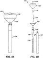
- Figures 4A and 4B illustrate the catheter 100 including an optional outer membrane 128.
- Figure 4B is an exploded view of Figure 4A .
- Electrodes (not illustrated) can be mounted over the balloon membrane 162, and wires (not illustrated) to the electrodes can be positioned between the balloon membrane 162 and outer membrane 128 similar to configurations of corresponding structures in U.S. 2020/0155266 .
- the catheter 100 can further include a third membrane configured similarly to corresponding structures in U.S. 2020/0155266 .
- the catheter 100 can include a navigation sensor 132 positioned in the shaft 130, for instance in the fourth lumen 124 ( Figure 3 ).
- the catheter 100 can include an inner ring 110 coupling the central tube 102 to the distal plug 106.
- the distal end 188 of the balloon 162 can be affixed to the inner ring 110, thereby fixing the distal end of the balloon 162 in relation to the central tube 102.
- the catheter 100 can include a coupler 108 coupling the proximal end 186 of the balloon 162 to the shaft 130.
- the catheter 100 can include a fluid impermeable coupler or seal 134 between the central tube 102 and the shaft 130 so that the fluid impermeable seal 134 is over the central tube and within the shaft.
- the seal 134 couples the central tube 102 to the inflation tube 116.
- the shaft 130 can include an inflation lumen sealed to the seal 134 (or similar seal 134 with appropriate configuration) to the central tube 102 so that the inflatable balloon 162 can be inflated directly through the inflation lumen without requiring the inflation tube 116.
- Figures 5A and 5B illustrate an alternative catheter 200 having an irrigation balloon 264 over an inflation balloon 262 and a central tube 202 providing structural support for the balloons 262, 264 and a flow path to inflate the inflation balloon 262.
- the central tube includes inflation ports 204.
- the central tube 202 can be configured to inflate and/or deflate the inflation balloon 262 similarly to the central tube 102 illustrated in Figures 1A through 4B .
- the central tube 102 can slide longitudinally in relation to a shaft 230 to adjust a longitudinal dimension, height H1, H3 of the balloons 262, 264.
- the central tube 202 can be obstructed by a distal plug 106 ( Figures 1A through 4D) or other obstruction to inhibit fluid from exiting the distal end 226 of the catheter 200.
- the irrigation balloon 264 and inner inflation balloon 262 are affixed to each other at a distal balloon end 288 and a proximal balloon end 286 fixed in relation to a catheter shaft 230.
- An irrigation lumen 266 provides a conduit for irrigation fluid to the irrigation balloon 264.
- the irrigation balloon 264 includes pores 272 sized and positioned to allow irrigation fluid to exit the interior of the irrigation balloon 264.
- the non-irrigating inner inflation balloon 262 is impermeable to the irrigation fluid such that no significant amount of irrigation fluid passes from the outer balloon 264 into the inner balloon 262 when negative pressure is applied to deflate the inner balloon 262, meaning any amount of irrigation fluid that may enter the inner balloon 262 during deflation does not significantly affect the resulting volume of the inner balloon 262.
- An inflation lumen 216 is fluidically coupled to the central tube 202.
- the irrigation lumen 266 and inflation lumen 216 are positioned in the shaft 230.
- the shaft 230, irrigation lumen 266, and inflation lumen 216 can have sufficient length to extend from the treatment site, through vasculature, and outside the patient.
- the distal portion of the catheter 200 can be placed by manipulation of a proximal portion of the shaft 230. Fluids can be injected into respective proximal openings of the irrigation lumen 266 and inflation lumen 268.
- the catheter 200 can include an inflation tube similar to the inflation tube 116 illustrated in Figure 4D.
- the catheter 200 can include a seal between the central tube 202 and shaft 230 to the irrigation lumen 266 similar to the seal 134 illustrated in Figure 4D.
- the volume of the inner balloon 262 can be deflated more rapidly than an equivalent volume of an irrigation balloon lacking the inner balloon structure 262. This is because, generally, an irrigation balloon includes pores that allow backflow of fluids into the volume of the irrigation balloon when negative pressure is applied to deflate the irrigation balloon.
- the catheter 200 can otherwise be manipulated and constructed similar to corresponding catheters in U.S. 2020/0147295 .
- the irrigation balloon 264 can expand and contract through a range of circumferences during inflation and deflation.
- the irrigation balloon 264 can have a small circumference C7 when in the deflated state ( Figure 5B ) sized so that the irrigation balloon 264 can be retracted into a sheath.
- the irrigation balloon 264 can have a maximum circumference C5 when in the inflated state ( Figure 5A ).
- the inner balloon 262 can expand and contract through a range of circumferences during inflation and deflation.
- the inner balloon 262 can have a small circumference C6 when the catheter 200 is in the deflated state ( Figure 5B ) and a larger circumference C4 when the catheter 200 is in an inflated state ( Figure 5A ).
- the circumference C4 of the inner inflation balloon 262 in the inflated state can be sized in relation to the circumference C5 of the irrigation balloon 264 in the inflated state ( Figure 5A ) to allow irrigation fluids to pass between the outer surface of the inner balloon 262 and the inner surface of the outer balloon 264 and through the pores 272 at a desired flow rate.
- the balloons 262, 264 When the balloons 262, 264 are in the inflated state as illustrated in Figure 5A , the balloons can respectively have circular cross-sectional shapes in plane P.
- the circular cross-sectional shapes of the balloons 262, 264 can be concentric.
- the central tube 202 can be concentric with the balloons 262, 264 in the plane P.
- the balloons 262, 264 can be substantially spherical as illustrated in Figure 5A or can form inflated shapes similar to those illustrated in Figures 1A and 1B .
- the central tube 202 can telescope to allow the irrigation balloon 264 and inner balloon 262 to contract and elongate during inflation and deflation.
- the balloons 262, 264 can have a maximum height H3 when in the deflated state ( Figure 5B ) and a minimum height H1 when in the inflated state ( Figure 5A ) similar to the example catheter 100 illustrated in Figures 1A and 1C .
- FIG 6 is an illustration of a distal portion of another example balloon catheter 300 having an expanding set of splines 356 and a collapsing set of splines 358.
- the balloon catheter 300 is illustrated in an inflated state.
- the catheter 300 includes a central tube 302 having inflation ports 304 configured to inflate a balloon 354 similar to the central tube 102 illustrated in Figures 1A through 4B .
- the central tube 302 can slide longitudinally in relation to a shaft 330 to adjust a longitudinal dimension, height H1, H2, H3 of a balloon 354 similar to as illustrated in Figures 1A through 1C .
- the central tube 302 can be obstructed by a distal plug 106 ( Figures 1A through 4D) or other obstruction to inhibit fluid from exiting the distal end of the catheter 300.
- the catheter 300 includes a balloon assembly 340 including the expanding set of splines 356, the collapsing set of splines 358, the balloon 354, and the central tube 302.
- the splines can be made at least partially from shape-memory material.
- the splines 356, 358 are preferably positioned inside the balloon 354, although they can be positioned outside the balloon 354.
- the splines 356, 358 can be configured to be heated using electrical current provided via suitable wires that run through the catheter's shaft 330.
- a physician may operate (e.g., activate and deactivate) each of the two sets of splines 356, 358 independently.
- the splines 356, 358 can be configured similarly to corresponding structures in U.S. 2019/0059818 .
- the catheter 300 can include additional compatible functionality and structures as presented in U.S. 2019/0059818 .
- the balloon 354 can be expanded by heating of the expanding set of splines 356, and the expanding set of splines 356 can be forced to collapse upon removal of heat.
- the balloon 354 can be collapsed by heating the collapsing set of splines 358, and the collapsing set of splines 358 can be forced to expand upon removal of the heat.
- the central tube 302 can slide longitudinally in relation to the shaft to longitudinally elongate and foreshorten the balloon 354.
- the splines 356, 358 can be affixed so that distal ends of the splines are fixed in relation to the central tube 302 and proximal ends of the splines are fixed in relation to the shaft 330.
- the central tube 302 can slide in relation to the shaft 330.
- the splines 356, 358 are distributed circumferentially around the inside of the balloon 354.
- the splines 356, 358 may be assembled in an alternating fashion, e.g., expanding splines 356 placed between two collapsing splines 358, and vice versa. This configuration balances the splines 356 that expand the balloon 354 the splines 358 that collapse and have it back mechanically ready to be easily pulled back into a sheath.
- the balloon assembly 340 can include a suitable number of splines, in various suitable arrangements.
- the number of expanding splines 356 can be different than the number of collapsing splines 358.
- the balloon assembly 340 can include one or more additional splines that are not made of a shape-memory material. More than two sets of splines can be used.
- the expanding set of splines 356 can be omitted, and pressure from inflation fluid within the balloon 354 can be sufficient to expand the balloon 354.
- the collapsing set of splines 358 can be activated to collapse the balloon 354 for re-sheathing.
- Figures 7A and 7B are illustrations of a distal portion of another example irrigation balloon catheter 400 having a self-expandable spring 451.
- Figure 7A illustrates the distal portion in a radially contracted, longitudinally extended state.
- Figure 7B illustrates the distal portion in a radially expanded, longitudinally retracted state.
- the catheter 400 includes a central tube 402 having inflation ports 404 configured to inflate a balloon 462 similar to the central tube 102 illustrated in Figures 1A through 4B .
- the central tube 402 can slide longitudinally in relation to a shaft 430 to adjust a longitudinal dimension, height H1, H2, H3 of a balloon 462 similar to as illustrated in Figures 1A through 1C .
- the central tube 402 can be obstructed by a distal plug 106 ( Figures 1A through 4D) or other obstruction to inhibit fluid from exiting the distal end of the catheter 400.
- Figure 7A illustrates a telescopic balloon assembly 440 of the catheter 400 in an elongated state fitted at the distal end of a shaft 430.
- a proximal section 448 and the central tube 402 are assembled into a two-part structure of the telescopic assembly 440.
- the proximal section 448 is tubular and shaped to receive the central tube 402.
- the proximal section 448 is coupled to the catheter shaft 430.
- the central tube 402 can move telescopically inside the proximal section 448, i.e., its motion is either proximally or distally along the longitudinal axis L-L.
- the balloon 462 is coupled at its distal end the central tube 402 by a distal anchor 456 and is coupled at its proximal end to the proximal section 448 by a proximal anchor 458.
- a puller-wire 452 runs through the shaft 430 and within the two-part telescopic assembly 440 and is connected to the central tube 402.
- the puller-wire 452 can be operated (e.g., pulled or relaxed) from a handle (not illustrated).
- the puller-wire 452 can be pulled to cause the central tube 402 to move into the proximal section 448, thereby foreshortening a longitudinal dimension (i.e. height) of the balloon 462 to move the telescopic assembly 440 from the longitudinally extended height illustrated in Figure 7A to the longitudinally retracted state illustrated in Figure 7B .
- a stopper 459 positioned on the central tube 402 can limit the motion of central tube 402 in the proximal direction when the stopper 459 contacts the proximal section 448.
- the balloon 462 can then be inflated as illustrated in Figure 7B .
- the spring 451 can provide a force to cause the telescopic assembly 440 to move from the longitudinally retracted state illustrated in Figure 7B to the longitudinally extended state illustrated in Figure 7A when tension on the puller-wire 452 is relaxed.
- the catheter 400 can include an inflation tube or inflation lumen similar to the inflation tube 116 and alternative inflation lumens described in relation to the catheter 100 illustrated in Figures 1A through 4B .
- the catheter 400 can include additional compatible functionality and structures as presented in U.S. 2019/0217065 .
- Figure 8 is an illustration of a system 10 for diagnosis and/or treatment of a heart 12 of a living patient 36.
- One commercial product embodying elements of system 10 is available as the CARTO ® 3 System, available from Biosense Webster, Inc. located in California, U.S.A.
- a balloon catheter 14 can be constructed and function similar to example catheters 100, 200, 300, 400 illustrated and described herein including those described in references incorporated by reference herein, variations thereof, and alternatives thereto as understood by a person skilled in the pertinent art according to the teachings herein.
- the balloon catheter 14 can further include compatible features of the various catheters 100, 200, 300, 400 illustrated and described herein including those described in the references incorporated by reference herein.
- the balloon catheter 14 can be percutaneously inserted by an operator 16 through the patient's vascular system and a shaft 30 of the catheter 14 can be manipulated to position a balloon 2 near a distal end of the balloon catheter 14 in a chamber or vascular structure of the heart 12.
- the operator 16 who is typically a physician, can inflate the balloon 2 and bring electrodes 42 on the balloon surface into contact with the heart wall, for example, at an ablation target site.
- the balloon can irrigate through pores 72.
- the balloon 2 can be configured to inflate via a central tube configured similarly to any of the central tubes 102, 202, 302, 402 illustrated herein, variations thereof, and alternatives thereto as understood by a person skilled in the pertinent art according to the teachings herein.
- the central tube can telescope to allow the height of the balloon 2 to foreshorten as the balloon 2 is inflated and/or elongate as the balloon 2 is deflated.
- Electrical signals measured by the electrodes 42 can be used to prepare electrical activation maps. Electrical activation maps can be prepared, according to methods disclosed in U.S. Patent Nos. 6,226,542 , 6,301,496 , and 6,892,091 , each incorporated herein by reference.
- Areas determined to be abnormal can be ablated by application of thermal energy, e.g., by passage of radiofrequency electrical current through wires in the balloon catheter 14 to one or more electrodes 42 positioned on the balloon 2, which apply the radiofrequency energy to target tissue.
- the electrodes 42 can be used both for measure electrical signals and apply radiofrequency ablation; alternatively, each process can be performed by different electrodes, potentially on different catheters.
- the catheter 14 can include a handle 20, having suitable controls on the handle to enable the operator 16 to steer, position and orient the distal end of the catheter as desired for ablation and/or diagnosis.
- the balloon catheter 14 can include position sensors positioned near the distal end of the balloon catheter 14 (e.g. under or near to the balloon 2) that provide signals to a processor 22, located in a console 24.
- the console 24 can include memory 58 in communication with the processor 22 that when executed by the processor 22 cause the console 24 to perform various functions during treatment.
- the console 24 can further include an ablation module 74, irrigation module 76, and inflation module 78 that can each respectively include hardware and software (e.g. in memory 58) to execute various functions related to the respective module.
- the modules 74, 76, 78 can include common hardware and/or software and are included to illustrate various functionality of the console 24.
- the console 24 can include additional modules not illustrated.
- the irrigation module 76 and inflation module 78 can be one in the same or separate (e.g. when the catheter 14 includes separate irrigation and inflation balloons).
- Ablation energy and electrical signals can be conveyed to and from the heart 12 through the electrodes 42 on the balloon 2 via a cable 38 to the console 24. Pacing signals and other control signals may be conveyed from the console 24 through the cable 38 and the electrodes 42 to the heart 12. This functionality can be controlled by the ablation module 74.
- Wire connections 35 link the console 24 with body surface electrodes 40 and other components of a positioning sub-system for measuring location and orientation coordinates of the catheter 14.
- the processor 22 or another processor may be an element of the positioning subsystem.
- the electrodes 42 on the balloon 2 and the body surface electrodes 40 may be used to measure tissue impedance at the ablation site as taught in U.S. Patent No. 7,536,218 , incorporated herein by reference.
- a temperature sensor typically a thermocouple or thermistor, may be mounted on or near each of the electrodes 42.
- An example of the temperature sensor as used in conjunction with the ablation electrode is shown and described in U.S. Patent Publication 2019/0298441 incorporated herein by reference.
- the catheter 14 can include a force sensor configured to provide a signal indicative of a magnitude and direction of force applied by a balloon on tissue such as described in U.S. Patent Application S.N. 16/863,815 filed April 30, 2020 , titled "Balloon Catheter with Force Sensor” with attorney docket number BI06131USNP1, incorporated by reference herein.
- the console 24 can include one or more ablation power generators 25 included in, or at least controlled by the ablation module 74.
- the catheter 14 can be configured to conduct ablative energy to the heart using any known ablation energies or modalities, e.g., radiofrequency energy, electroporation, ultrasound energy, cryogenic energy, and laser-produced light energy.
- ablation energies or modalities e.g., radiofrequency energy, electroporation, ultrasound energy, cryogenic energy, and laser-produced light energy.
- the positioning subsystem can include a magnetic position tracking arrangement that determines the position and orientation of the catheter 14 by generating magnetic fields, using magnetic field generators 28, in a predefined working volume and sensing these fields at the catheter, using coils or traces disposed within the catheter, typically proximate to the tip.
- a positioning subsystem is described in U.S. Patent No. 7,756,576 and U.S. Patent No. 7,536,218 , each incorporated herein in their entireties.
- the operator 16 may observe and regulate the functions of the catheter 14 via the console 24.
- the processor 22 can drive a display 29.
- the processor 22 and associated circuitry of the console 24 can be configured to receive, amplify, filter and digitize signals from the catheter 14, including signals generated by sensors such as electrical, temperature and contact force sensors, and a plurality of location sensing coils or traces located distally in the catheter 14.
- the digitized signals are received and used by the console 24 and the positioning subsystem to compute the position and orientation of the catheter 14, and to analyze the electrical signals from the electrodes and sensors.
- the processor 22 can include an electroanatomic map generator, an image registration program, an image or data analysis program and a graphical user interface configured to present graphical information on the display 29.
- the system 10 can include other elements, which are not shown in the figures for the sake of simplicity.
- the system 10 can include an electrocardiogram (ECG) monitor, coupled to receive signals from one or more body surface electrodes, in order to provide an ECG synchronization signal to the console 24.
- ECG electrocardiogram
- the system 10 can include a reference position sensor, either on an externally applied reference patch attached to the exterior of the subject's body, or on an internally placed catheter, which is inserted into the heart 12 maintained in a fixed position relative to the heart 12.
- the system 10 can further include pumps and lines for circulating liquids through the catheter 14 for irrigating the treatment site.
- the system 10 can be configured to receive image data from an external imaging modality, such as an MRI unit, CT, or the like and includes image processors that can be incorporated in or invoked by the processor 22 for generating and displaying images.
Landscapes
- Health & Medical Sciences (AREA)
- Life Sciences & Earth Sciences (AREA)
- Heart & Thoracic Surgery (AREA)
- Engineering & Computer Science (AREA)
- Biomedical Technology (AREA)
- Public Health (AREA)
- Veterinary Medicine (AREA)
- Animal Behavior & Ethology (AREA)
- General Health & Medical Sciences (AREA)
- Biophysics (AREA)
- Anesthesiology (AREA)
- Hematology (AREA)
- Surgery (AREA)
- Child & Adolescent Psychology (AREA)
- Pulmonology (AREA)
- Molecular Biology (AREA)
- Medical Informatics (AREA)
- Physics & Mathematics (AREA)
- Cardiology (AREA)
- Pathology (AREA)
- Physiology (AREA)
- Otolaryngology (AREA)
- Nuclear Medicine, Radiotherapy & Molecular Imaging (AREA)
- Plasma & Fusion (AREA)
- Media Introduction/Drainage Providing Device (AREA)
- Surgical Instruments (AREA)
Applications Claiming Priority (2)
| Application Number | Priority Date | Filing Date | Title |
|---|---|---|---|
| US202163137270P | 2021-01-14 | 2021-01-14 | |
| US17/546,252 US11957852B2 (en) | 2021-01-14 | 2021-12-09 | Intravascular balloon with slidable central irrigation tube |
Publications (2)
| Publication Number | Publication Date |
|---|---|
| EP4029556A2 true EP4029556A2 (fr) | 2022-07-20 |
| EP4029556A3 EP4029556A3 (fr) | 2022-11-02 |
Family
ID=79601548
Family Applications (1)
| Application Number | Title | Priority Date | Filing Date |
|---|---|---|---|
| EP22151293.2A Pending EP4029556A3 (fr) | 2021-01-14 | 2022-01-13 | Ballonnet intravasculaire comportant un tube d'irrigation central coulissant |
Country Status (5)
| Country | Link |
|---|---|
| US (1) | US11957852B2 (fr) |
| EP (1) | EP4029556A3 (fr) |
| JP (2) | JP2022109241A (fr) |
| CN (1) | CN114762750A (fr) |
| IL (1) | IL289567B2 (fr) |
Families Citing this family (5)
| Publication number | Priority date | Publication date | Assignee | Title |
|---|---|---|---|---|
| CN121079048B (zh) * | 2023-03-03 | 2026-04-10 | 塞纳医疗公司 | 用于分流导管的可扩展元件 |
| US20250228596A1 (en) * | 2024-01-16 | 2025-07-17 | Aventix Medical Inc. | Pulsed field electroporation systems and methods |
| US20250352031A1 (en) * | 2024-05-14 | 2025-11-20 | Cardiofocus, Inc. | Ablation Catheters with Deployable Electrode Structures for Use in Ablation and Electrophysiological Mapping |
| CN118846346B (zh) * | 2024-07-12 | 2025-09-26 | 普利瑞医疗科技(苏州)有限公司 | 一种导管用球囊和球囊扩张导管 |
| CN119075151B (zh) * | 2024-09-25 | 2025-09-26 | 普利瑞医疗科技(苏州)有限公司 | 一种止血囊体导管系统 |
Citations (20)
| Publication number | Priority date | Publication date | Assignee | Title |
|---|---|---|---|---|
| US6226542B1 (en) | 1998-07-24 | 2001-05-01 | Biosense, Inc. | Three-dimensional reconstruction of intrabody organs |
| US6301496B1 (en) | 1998-07-24 | 2001-10-09 | Biosense, Inc. | Vector mapping of three-dimensionally reconstructed intrabody organs and method of display |
| US6814733B2 (en) | 2002-01-31 | 2004-11-09 | Biosense, Inc. | Radio frequency pulmonary vein isolation |
| US6892091B1 (en) | 2000-02-18 | 2005-05-10 | Biosense, Inc. | Catheter, method and apparatus for generating an electrical map of a chamber of the heart |
| US6997924B2 (en) | 2002-09-17 | 2006-02-14 | Biosense Inc. | Laser pulmonary vein isolation |
| US7156816B2 (en) | 2002-11-26 | 2007-01-02 | Biosense, Inc. | Ultrasound pulmonary vein isolation |
| US7410486B2 (en) | 2002-07-23 | 2008-08-12 | Biosense Webster, Inc. | Ablation catheter having stabilizing array |
| US7536218B2 (en) | 2005-07-15 | 2009-05-19 | Biosense Webster, Inc. | Hybrid magnetic-based and impedance-based position sensing |
| US7756576B2 (en) | 2005-08-26 | 2010-07-13 | Biosense Webster, Inc. | Position sensing and detection of skin impedance |
| US20120226230A1 (en) * | 2011-03-01 | 2012-09-06 | Gerrans Lawrence J | Nested Balloon Catheter for Localized Drug Delivery |
| US9907610B2 (en) | 2015-05-07 | 2018-03-06 | Biosense Webster (Israel) Ltd. | Spring-loaded balloon |
| US20180140807A1 (en) | 2016-11-23 | 2018-05-24 | Biosense Webster (Israel) Ltd. | Double balloon catheter having a lobed inner balloon |
| US20180161093A1 (en) | 2016-12-08 | 2018-06-14 | Biosense Webster (Israel) Ltd. | Irrigated balloon catheter with support spines and variable shape |
| US20190059818A1 (en) | 2017-08-29 | 2019-02-28 | Biosense Webster (Israel) Ltd. | Balloon advancement mechanism |
| US20190201669A1 (en) | 2017-12-28 | 2019-07-04 | Biosense Webster (Israel) Ltd. | Balloon catheter with internal distal end |
| US20190217065A1 (en) | 2018-01-12 | 2019-07-18 | Biosense Webster (Israel) Ltd. | Balloon Catheter Assisted by Pulling a Puller-Wire |
| US20190298441A1 (en) | 2018-03-28 | 2019-10-03 | Biosense Webster (Israel) Ltd. | Irrigated electrophysiology catheter with distinguishable electrodes for multi-electrode identification and orientation under 2-d visualization |
| US20200147295A1 (en) | 2016-11-23 | 2020-05-14 | Biosense Webster (Israel) Ltd. | Balloon-in-balloon irrigation balloon catheter |
| US20200155266A1 (en) | 2017-05-05 | 2020-05-21 | Creo Medical Limited | Apparatus for sterilising an instrument channel of a surgical scoping device |
| US20200155226A1 (en) | 2018-11-19 | 2020-05-21 | Biosense Webster (Israel) Ltd. | Medical Probe with Wiring Disposed Between Two Expandable Membranes |
Family Cites Families (253)
| Publication number | Priority date | Publication date | Assignee | Title |
|---|---|---|---|---|
| FR1344459A (fr) | 1962-10-18 | 1963-11-29 | Procédé et appareil pour l'étude électrique des organismes vivants | |
| US4276874A (en) | 1978-11-15 | 1981-07-07 | Datascope Corp. | Elongatable balloon catheter |
| US4299227A (en) | 1979-10-19 | 1981-11-10 | Lincoff Harvey A | Ophthalmological appliance |
| US4587975A (en) | 1984-07-02 | 1986-05-13 | Cardiac Pacemakers, Inc. | Dimension sensitive angioplasty catheter |
| US4709698A (en) | 1986-05-14 | 1987-12-01 | Thomas J. Fogarty | Heatable dilation catheter |
| DE3775281D1 (de) | 1986-06-16 | 1992-01-30 | Siemens Ag | Vorrichtung zur steuerung eines herzschrittmachers mittels impedanzmessung an koerpergeweben. |
| US4796629A (en) | 1987-06-03 | 1989-01-10 | Joseph Grayzel | Stiffened dilation balloon catheter device |
| US5178957A (en) | 1989-05-02 | 1993-01-12 | Minnesota Mining And Manufacturing Company | Noble metal-polymer composites and flexible thin-film conductors prepared therefrom |
| JP2891032B2 (ja) | 1993-03-15 | 1999-05-17 | 日本ゼオン株式会社 | バルーンカテーテル |
| US5860974A (en) | 1993-07-01 | 1999-01-19 | Boston Scientific Corporation | Heart ablation catheter with expandable electrode and method of coupling energy to an electrode on a catheter shaft |
| US20020002369A1 (en) | 1993-08-23 | 2002-01-03 | Hood Larry L. | Method and apparatus for modifying visual acuity by moving a focal point of energy within a cornea |
| US5582609A (en) | 1993-10-14 | 1996-12-10 | Ep Technologies, Inc. | Systems and methods for forming large lesions in body tissue using curvilinear electrode elements |
| US5797903A (en) | 1996-04-12 | 1998-08-25 | Ep Technologies, Inc. | Tissue heating and ablation systems and methods using porous electrode structures with electrically conductive surfaces |
| US5429617A (en) | 1993-12-13 | 1995-07-04 | The Spectranetics Corporation | Radiopaque tip marker for alignment of a catheter within a body |
| US5584830A (en) | 1994-03-30 | 1996-12-17 | Medtronic Cardiorhythm | Method and system for radiofrequency ablation of cardiac tissue |
| WO1996000528A1 (fr) | 1994-06-27 | 1996-01-11 | Ep Technologies, Inc. | Systemes et procedes de commande non lineaire permettant de chauffer des tissus humains et pratiquer leur ablation |
| US6690963B2 (en) | 1995-01-24 | 2004-02-10 | Biosense, Inc. | System for determining the location and orientation of an invasive medical instrument |
| US5718241A (en) | 1995-06-07 | 1998-02-17 | Biosense, Inc. | Apparatus and method for treating cardiac arrhythmias with no discrete target |
| US6322558B1 (en) | 1995-06-09 | 2001-11-27 | Engineering & Research Associates, Inc. | Apparatus and method for predicting ablation depth |
| NL1001890C2 (nl) | 1995-12-13 | 1997-06-17 | Cordis Europ | Catheter met plaatvormige elektrode-reeks. |
| WO1997025917A1 (fr) | 1996-01-19 | 1997-07-24 | Ep Technologies, Inc. | Structures multifonctionnelles d'electrodes destinees a l'analyse et au chauffage electriques de tissus corporels |
| US6719755B2 (en) | 1996-10-22 | 2004-04-13 | Epicor Medical, Inc. | Methods and devices for ablation |
| US6012457A (en) | 1997-07-08 | 2000-01-11 | The Regents Of The University Of California | Device and method for forming a circumferential conduction block in a pulmonary vein |
| US6024740A (en) | 1997-07-08 | 2000-02-15 | The Regents Of The University Of California | Circumferential ablation device assembly |
| US5971983A (en) | 1997-05-09 | 1999-10-26 | The Regents Of The University Of California | Tissue ablation device and method of use |
| US6164283A (en) | 1997-07-08 | 2000-12-26 | The Regents Of The University Of California | Device and method for forming a circumferential conduction block in a pulmonary vein |
| US6997925B2 (en) | 1997-07-08 | 2006-02-14 | Atrionx, Inc. | Tissue ablation device assembly and method for electrically isolating a pulmonary vein ostium from an atrial wall |
| US6652515B1 (en) | 1997-07-08 | 2003-11-25 | Atrionix, Inc. | Tissue ablation device assembly and method for electrically isolating a pulmonary vein ostium from an atrial wall |
| US6500174B1 (en) | 1997-07-08 | 2002-12-31 | Atrionix, Inc. | Circumferential ablation device assembly and methods of use and manufacture providing an ablative circumferential band along an expandable member |
| US6966908B2 (en) | 1997-07-08 | 2005-11-22 | Atrionix, Inc. | Tissue ablation device assembly and method for electrically isolating a pulmonary vein ostium from an atrial wall |
| JP3857788B2 (ja) | 1997-09-01 | 2006-12-13 | テルモ株式会社 | 循環器情報計測システム |
| US6093185A (en) | 1998-03-05 | 2000-07-25 | Scimed Life Systems, Inc. | Expandable PMR device and method |
| US6042580A (en) | 1998-05-05 | 2000-03-28 | Cardiac Pacemakers, Inc. | Electrode having composition-matched, common-lead thermocouple wire for providing multiple temperature-sensitive junctions |
| US6522930B1 (en) | 1998-05-06 | 2003-02-18 | Atrionix, Inc. | Irrigated ablation device assembly |
| US6198974B1 (en) | 1998-08-14 | 2001-03-06 | Cordis Webster, Inc. | Bi-directional steerable catheter |
| US6123718A (en) | 1998-11-02 | 2000-09-26 | Polymerex Medical Corp. | Balloon catheter |
| US6171275B1 (en) | 1998-12-03 | 2001-01-09 | Cordis Webster, Inc. | Irrigated split tip electrode catheter |
| US6380957B1 (en) | 1998-12-15 | 2002-04-30 | International Business Machines Corporation | Method of controlling view of large expansion tree |
| US6986744B1 (en) | 1999-02-02 | 2006-01-17 | Transonic Systems, Inc. | Method and apparatus for determining blood flow during a vascular corrective procedure |
| US6702811B2 (en) | 1999-04-05 | 2004-03-09 | Medtronic, Inc. | Ablation catheter assembly with radially decreasing helix and method of use |
| EP1790304B1 (fr) | 1999-05-11 | 2016-08-31 | Atrionix, Inc. | Système d'ablation de tissus comprenant un fil d'ancrage à ballonet |
| US6696844B2 (en) | 1999-06-04 | 2004-02-24 | Engineering & Research Associates, Inc. | Apparatus and method for real time determination of materials' electrical properties |
| US7935108B2 (en) | 1999-07-14 | 2011-05-03 | Cardiofocus, Inc. | Deflectable sheath catheters |
| US6471693B1 (en) | 1999-09-10 | 2002-10-29 | Cryocath Technologies Inc. | Catheter and system for monitoring tissue contact |
| US7020400B2 (en) | 1999-12-24 | 2006-03-28 | Altera Corporation | Multi-wavelength optical communication system |
| US6546935B2 (en) | 2000-04-27 | 2003-04-15 | Atricure, Inc. | Method for transmural ablation |
| US6656174B1 (en) | 2000-07-20 | 2003-12-02 | Scimed Life Systems, Inc. | Devices and methods for creating lesions in blood vessels without obstructing blood flow |
| AU2001279026B2 (en) | 2000-07-25 | 2005-12-22 | Angiodynamics, Inc. | Apparatus for detecting and treating tumors using localized impedance measurement |
| US6974457B2 (en) | 2001-01-11 | 2005-12-13 | C.R. Bard Inc. | Ablation catheter |
| US6743225B2 (en) | 2001-03-27 | 2004-06-01 | Uab Research Foundation | Electrophysiologic measure of endpoints for ablation lesions created in fibrillating substrates |
| USD462389S1 (en) | 2001-04-27 | 2002-09-03 | Marie R. Provence | Teaching aid for learning to tell time |
| US6732734B2 (en) | 2001-04-27 | 2004-05-11 | Kuraray Co., Ltd. | Pilot balloon for balloon catheters |
| US20030018327A1 (en) | 2001-07-20 | 2003-01-23 | Csaba Truckai | Systems and techniques for lung volume reduction |
| CA2453568A1 (fr) | 2001-08-31 | 2003-03-13 | Scimed Life Systems, Inc. | Dispositif et procede d'occlusion percutanee de type pringle |
| CA2500853A1 (fr) | 2002-10-04 | 2004-04-22 | Cook Urological, Incorporated | Extracteur rigide avec pince a panier |
| US7306593B2 (en) | 2002-10-21 | 2007-12-11 | Biosense, Inc. | Prediction and assessment of ablation of cardiac tissue |
| US6893433B2 (en) | 2002-12-11 | 2005-05-17 | Cryocor, Inc. | System and method for performing a single step cryoablation |
| JP2006518648A (ja) | 2003-02-20 | 2006-08-17 | プロリズム,インコーポレイテッド | 心臓アブレーションデバイス |
| US7142903B2 (en) | 2003-03-12 | 2006-11-28 | Biosense Webster, Inc. | Catheter with contractable mapping assembly |
| US6987995B2 (en) | 2003-03-12 | 2006-01-17 | Biosense Webster, Inc. | Multifunctional catheter handle |
| US7293562B2 (en) | 2003-03-27 | 2007-11-13 | Cierra, Inc. | Energy based devices and methods for treatment of anatomic tissue defects |
| US7410483B2 (en) | 2003-05-23 | 2008-08-12 | Novare Surgical Systems, Inc. | Hand-actuated device for remote manipulation of a grasping tool |
| JP2005052424A (ja) | 2003-08-05 | 2005-03-03 | Matsushita Electric Ind Co Ltd | 超音波診断装置 |
| US7682521B2 (en) | 2003-08-22 | 2010-03-23 | The Regents Of The University Of Colorado | Aligned liquid crystal thin films and glasses |
| US8292943B2 (en) | 2003-09-03 | 2012-10-23 | Bolton Medical, Inc. | Stent graft with longitudinal support member |
| ES2564694T3 (es) | 2003-09-12 | 2016-03-28 | Vessix Vascular, Inc. | Sistema de remodelación y / o ablación excéntrica seleccionable de material ateroesclerótico |
| US7435248B2 (en) | 2003-09-26 | 2008-10-14 | Boston Scientific Scimed, Inc. | Medical probes for creating and diagnosing circumferential lesions within or around the ostium of a vessel |
| US7695491B2 (en) | 2003-12-01 | 2010-04-13 | Ev3 Inc. | Rapid exchange catheters with tandem lumens |
| JP4391221B2 (ja) | 2003-12-22 | 2009-12-24 | 有限会社日本エレクテル | 高周波加温バルーンカテーテル |
| US8460286B2 (en) | 2004-01-16 | 2013-06-11 | St. Jude Medical, Atrial Fibrillation Division, Inc. | Conforming electrode |
| US7591799B2 (en) | 2004-06-14 | 2009-09-22 | Biosense Webster, Inc. | Steering mechanism for bi-directional catheter |
| US7377906B2 (en) | 2004-06-15 | 2008-05-27 | Biosense Webster, Inc. | Steering mechanism for bi-directional catheter |
| US9713730B2 (en) | 2004-09-10 | 2017-07-25 | Boston Scientific Scimed, Inc. | Apparatus and method for treatment of in-stent restenosis |
| US7914487B2 (en) | 2004-10-15 | 2011-03-29 | Futurematrix Interventional, Inc. | Non-compliant medical balloon having braided or knitted reinforcement |
| US8617152B2 (en) | 2004-11-15 | 2013-12-31 | Medtronic Ablation Frontiers Llc | Ablation system with feedback |
| US20060135953A1 (en) | 2004-12-22 | 2006-06-22 | Wlodzimierz Kania | Tissue ablation system including guidewire with sensing element |
| DE102005012739B4 (de) | 2005-03-19 | 2010-09-16 | MAX-PLANCK-Gesellschaft zur Förderung der Wissenschaften e.V. | Verfahren zur Herstellung räumlicher Feinstrukturen |
| US7442190B2 (en) | 2005-05-13 | 2008-10-28 | Cryocath Technologies Inc. | Contact assessment of balloon catheters |
| CN101309651B (zh) | 2005-06-20 | 2011-12-07 | 麦德托尼克消融前沿有限公司 | 消融导管 |
| CA2621657C (fr) | 2005-09-21 | 2014-06-17 | Surmodics, Inc. | Occlusion in situ utilisant des polysaccharides biodegradables naturels |
| US7842031B2 (en) | 2005-11-18 | 2010-11-30 | Medtronic Cryocath Lp | Bioimpedance measurement system and method |
| US8696656B2 (en) | 2005-11-18 | 2014-04-15 | Medtronic Cryocath Lp | System and method for monitoring bioimpedance and respiration |
| US8048032B2 (en) | 2006-05-03 | 2011-11-01 | Vascular Solutions, Inc. | Coaxial guide catheter for interventional cardiology procedures |
| US8677280B2 (en) | 2006-05-18 | 2014-03-18 | Ubiquity Broadcasting Corporation | Sprocket shaped user interface for navigating a dynamic collection of information |
| US20070287994A1 (en) | 2006-06-12 | 2007-12-13 | Pankaj Amrit Patel | Endoscopically Introducible Expandable Bipolar Probe |
| US20100114269A1 (en) | 2006-06-28 | 2010-05-06 | Medtronic Cryocath Lp | Variable geometry balloon catheter and method |
| US8694076B2 (en) | 2006-07-06 | 2014-04-08 | Boston Scientific Scimed, Inc. | Electroactive polymer radiopaque marker |
| US7985228B2 (en) | 2006-08-25 | 2011-07-26 | Kyphon Sarl | Apparatus and methods for use of expandable members in surgical applications |
| US7691080B2 (en) | 2006-09-21 | 2010-04-06 | Mercator Medsystems, Inc. | Dual modulus balloon for interventional procedures |
| EP2076194B1 (fr) | 2006-10-18 | 2013-04-24 | Vessix Vascular, Inc. | Système pour induire des effets thermiques désirables sur un tissu anatomique |
| US7867227B2 (en) | 2007-02-22 | 2011-01-11 | A David Slater | Bipolar cardiac ablation system and method |
| US7993537B2 (en) | 2007-02-23 | 2011-08-09 | GM Global Technology Operations LLC | Method for improving adhesion between a shape memory alloy and a polymer |
| US8764742B2 (en) | 2007-04-04 | 2014-07-01 | St. Jude Medical, Atrial Fibrillation Division, Inc. | Irrigated catheter |
| US8496653B2 (en) | 2007-04-23 | 2013-07-30 | Boston Scientific Scimed, Inc. | Thrombus removal |
| US8641704B2 (en) | 2007-05-11 | 2014-02-04 | Medtronic Ablation Frontiers Llc | Ablation therapy system and method for treating continuous atrial fibrillation |
| US20090270850A1 (en) | 2007-06-20 | 2009-10-29 | Tea Time Partners, L.P., Organized In Texas | Devices and methods for the ablation of tissue in the lateral direction |
| US9283034B2 (en) | 2007-09-26 | 2016-03-15 | Retrovascular, Inc. | Recanalization system using radiofrequency energy |
| JP2009089806A (ja) | 2007-10-05 | 2009-04-30 | Asahi Intecc Co Ltd | バルーンカテーテル |
| US8357152B2 (en) | 2007-10-08 | 2013-01-22 | Biosense Webster (Israel), Ltd. | Catheter with pressure sensing |
| JP5302321B2 (ja) | 2007-10-12 | 2013-10-02 | コンメッド コーポレーション | 心拍出量測定装置および方法 |
| US9101431B2 (en) | 2007-11-01 | 2015-08-11 | Stephen B. Murphy | Guide for acetabular component positioning |
| US9717501B2 (en) | 2007-11-21 | 2017-08-01 | St. Jude Medical, Atrial Fibrillation Division, Inc. | Methods and systems for occluding vessels during cardiac ablation including optional electroanatomical guidance |
| US9126023B1 (en) | 2007-12-14 | 2015-09-08 | Gmedelaware 2 Llc | Balloon expandable cement director and related methods |
| US20090163890A1 (en) | 2007-12-20 | 2009-06-25 | Acclarent, Inc. | Method and System for Accessing, Diagnosing and Treating Target Tissue Regions Within the Middle Ear and the Eustachian Tube |
| WO2010033266A2 (fr) | 2008-05-02 | 2010-03-25 | Battelle Memorial Institute | Panneau composite léger atténuateur de souffle |
| EP2300094B1 (fr) * | 2008-06-02 | 2013-07-24 | Loma Vista Medical, Inc., | Dispositifs médicaux gonflables |
| DE102008062021A1 (de) | 2008-08-18 | 2010-03-04 | Epcos Ag | Piezoaktor in Vielschichtbauweise |
| JP4649506B2 (ja) | 2008-09-16 | 2011-03-09 | 有限会社日本エレクテル | 高周波加温バルーンカテーテル |
| US9545216B2 (en) | 2011-08-05 | 2017-01-17 | Mc10, Inc. | Catheter balloon methods and apparatus employing sensing elements |
| WO2010056771A1 (fr) | 2008-11-11 | 2010-05-20 | Shifamed Llc | Ensemble d’électrodes à faible profil |
| WO2013154776A2 (fr) | 2012-04-13 | 2013-10-17 | Covidien Lp | Dispositif d'alimentation en énergie et procédés d'utilisation |
| US9795442B2 (en) | 2008-11-11 | 2017-10-24 | Shifamed Holdings, Llc | Ablation catheters |
| US11376061B2 (en) | 2008-11-11 | 2022-07-05 | Covidien Lp | Energy delivery device and methods of use |
| US20100256629A1 (en) | 2009-04-06 | 2010-10-07 | Voyage Medical, Inc. | Methods and devices for treatment of the ostium |
| US8551096B2 (en) | 2009-05-13 | 2013-10-08 | Boston Scientific Scimed, Inc. | Directional delivery of energy and bioactives |
| US9754025B2 (en) | 2009-08-13 | 2017-09-05 | TunesMap Inc. | Analyzing captured sound and seeking a match based on an acoustic fingerprint for temporal and geographic presentation and navigation of linked cultural, artistic, and historic content |
| US10688278B2 (en) | 2009-11-30 | 2020-06-23 | Biosense Webster (Israel), Ltd. | Catheter with pressure measuring tip |
| US9445859B2 (en) | 2010-01-29 | 2016-09-20 | Medtronic Cryocath Lp | Multifunctional ablation device |
| WO2011127216A2 (fr) | 2010-04-06 | 2011-10-13 | Innovative Pulmonary Solutions, Inc. | Système et méthode de traitement pulmonaire |
| EP2568905A4 (fr) | 2010-05-12 | 2017-07-26 | Shifamed Holdings, LLC | Assemblage d'électrode à faible profil |
| US9655677B2 (en) | 2010-05-12 | 2017-05-23 | Shifamed Holdings, Llc | Ablation catheters including a balloon and electrodes |
| US9744339B2 (en) | 2010-05-12 | 2017-08-29 | Circa Scientific, Llc | Apparatus for manually manipulating hollow organs |
| US9173705B2 (en) | 2010-05-13 | 2015-11-03 | Ncontact Surgical, Inc. | Subxyphoid epicardial ablation |
| US20110295247A1 (en) | 2010-05-28 | 2011-12-01 | Hansen Medical, Inc. | System and method for automated minimally invasive therapy using radiometry |
| JP5615073B2 (ja) | 2010-07-20 | 2014-10-29 | オムロンヘルスケア株式会社 | 測定装置 |
| US9463062B2 (en) | 2010-07-30 | 2016-10-11 | Boston Scientific Scimed, Inc. | Cooled conductive balloon RF catheter for renal nerve ablation |
| US8903473B2 (en) | 2010-09-15 | 2014-12-02 | Medtronic, Inc. | Radiopaque markers for implantable medical devices |
| JP2013544565A (ja) | 2010-10-20 | 2013-12-19 | メドトロニック アーディアン ルクセンブルク ソシエテ ア レスポンサビリテ リミテ | 腎神経調節のための拡張可能なメッシュ構造を有するカテーテル器具並びに関連するシステムおよび方法 |
| CN103313671B (zh) | 2010-10-25 | 2017-06-06 | 美敦力Af卢森堡有限责任公司 | 用于神经调节治疗的估算及反馈的装置、系统及方法 |
| JP2013544133A (ja) | 2010-10-25 | 2013-12-12 | メドトロニック アーディアン ルクセンブルク ソシエテ ア レスポンサビリテ リミテ | 腎ニューロモジュレーションのためのマルチ電極アレイを有するカテーテル装置ならびに関連のシステムおよび方法 |
| US9089350B2 (en) | 2010-11-16 | 2015-07-28 | Boston Scientific Scimed, Inc. | Renal denervation catheter with RF electrode and integral contrast dye injection arrangement |
| US20120130646A1 (en) | 2010-11-19 | 2012-05-24 | Lifescan, Inc. | Analyte testing method and system with high and low analyte trends notification |
| US8998893B2 (en) | 2010-12-07 | 2015-04-07 | Boaz Avitall | Catheter systems for cardiac arrhythmia ablation |
| US11246653B2 (en) | 2010-12-07 | 2022-02-15 | Boaz Avitall | Catheter systems for cardiac arrhythmia ablation |
| US20120165732A1 (en) * | 2010-12-23 | 2012-06-28 | Synthes Usa, Llc | Balloon catheter comprising a zero-profile tip |
| US9149327B2 (en) | 2010-12-27 | 2015-10-06 | St. Jude Medical Luxembourg Holding S.À.R.L. | Prediction of atrial wall electrical reconnection based on contact force measured during RF ablation |
| WO2012100211A2 (fr) | 2011-01-20 | 2012-07-26 | Hansen Medical, Inc. | Système et procédé de thérapie endoluminale et transluminale |
| US8647358B2 (en) | 2011-01-21 | 2014-02-11 | Obalon Therapeutics Inc. | Intragastric device |
| US9757044B2 (en) | 2011-03-10 | 2017-09-12 | Acutus Medical, Inc. | Device and method for the geometric determination of electrical dipole densities on the cardiac wall |
| US20140227437A1 (en) | 2011-05-23 | 2014-08-14 | California Institute Of Technology | Accommodating intraocular lens |
| US8975107B2 (en) | 2011-06-16 | 2015-03-10 | Infineon Techologies Ag | Method of manufacturing a semiconductor device comprising a membrane over a substrate by forming a plurality of features using local oxidation regions |
| US9220433B2 (en) | 2011-06-30 | 2015-12-29 | Biosense Webster (Israel), Ltd. | Catheter with variable arcuate distal section |
| DE102011083522B4 (de) | 2011-09-27 | 2015-06-18 | Friedrich-Alexander-Universität Erlangen-Nürnberg | Verfahren und Vorrichtung zur Visualisierung der Qualität eines Ablationsvorgangs |
| CN103826694B (zh) | 2011-09-30 | 2017-03-22 | 柯惠有限合伙公司 | 能量传递装置以及使用方法 |
| US8498686B2 (en) | 2011-10-04 | 2013-07-30 | Biosense Webster (Israel), Ltd. | Mapping catheter with spiral electrode assembly |
| JP6277130B2 (ja) | 2011-10-05 | 2018-02-14 | エムシーテン、インコーポレイテッド | 医療用の装置およびそれの製造方法 |
| US20130090649A1 (en) | 2011-10-11 | 2013-04-11 | Boston Scientific Scimed, Inc. | Device and methods for renal nerve modulation |
| JP6158830B2 (ja) | 2011-12-23 | 2017-07-05 | べシックス・バスキュラー・インコーポレイテッド | 身体通路の組織又は身体通路に隣接する組織をリモデリングするためのシステム、方法及び装置 |
| USD682291S1 (en) | 2012-01-08 | 2013-05-14 | In Baek | Display screen with graphical user interface |
| USD682289S1 (en) | 2012-01-08 | 2013-05-14 | Noah DiJulio | Display screen with graphical user interface |
| USD690318S1 (en) | 2012-01-12 | 2013-09-24 | Lenovo (Singapore) Pte. Ltd. | Information handling device with graphical user interface |
| EP2822635B8 (fr) | 2012-03-09 | 2018-11-14 | Clearstream Technologies Limited | Ballonnet médical comprenant un identificateur radiopaque pour identifier avec précision la surface de travail |
| EP2830702A4 (fr) | 2012-03-27 | 2015-12-09 | Ralph Peter Cardinal | Système de neuromodulation et procédés associés |
| AU344772S (en) | 2012-05-02 | 2012-10-09 | Samsung Electronics Co Ltd | Display screen for an electronic device |
| US20130317339A1 (en) * | 2012-05-23 | 2013-11-28 | Biosense Webster (Israel), Ltd. | Endobronchial catheter |
| WO2013184945A1 (fr) | 2012-06-06 | 2013-12-12 | Loma Vista Medical, Inc. | Dispositifs médicaux gonflables |
| USD724618S1 (en) | 2012-06-28 | 2015-03-17 | Samsung Electronics Co., Ltd. | Portable electronic device with a graphical user interface |
| WO2014008489A1 (fr) | 2012-07-04 | 2014-01-09 | Cibiem, Inc. | Dispositifs et systèmes pour l'ablation de corps carotidien |
| KR20150031324A (ko) | 2012-07-05 | 2015-03-23 | 엠씨10, 인크 | 유동 감지를 포함하는 카테터 장치 |
| US9545290B2 (en) | 2012-07-30 | 2017-01-17 | Ethicon Endo-Surgery, Inc. | Needle probe guide |
| USD720766S1 (en) | 2012-09-10 | 2015-01-06 | Lookout, Inc. | Mobile communication device display with graphical user interface comprising security and privacy advisor screens |
| USD716340S1 (en) | 2012-09-28 | 2014-10-28 | Google Inc. | Display screen or portion thereof for a control unit with animated graphical user interface |
| AU347958S (en) | 2012-10-18 | 2013-04-09 | Samsung Electronics Co Ltd | Display screen for an electronic device |
| USD736780S1 (en) | 2012-12-27 | 2015-08-18 | Lenovo (Beijing) Co., Ltd. | Display screen or portion thereof with animated graphical user interface |
| USD749606S1 (en) | 2012-12-27 | 2016-02-16 | Lenovo (Beijing) Co., Ltd. | Display screen with graphical user interface |
| US9050010B2 (en) | 2012-12-31 | 2015-06-09 | Biosense Webster (Israel) Ltd. | Double loop lasso with single puller wire for bi-directional actuation |
| US10939822B2 (en) | 2013-01-24 | 2021-03-09 | Tylerton International Holdings Inc. | Body structure imaging |
| USD694652S1 (en) | 2013-01-30 | 2013-12-03 | MerchSource, LLC | Alarm clock |
| JP2016508834A (ja) | 2013-03-13 | 2016-03-24 | ボストン サイエンティフィック サイムド,インコーポレイテッドBoston Scientific Scimed,Inc. | 直線的イオン伝導性バルーンを備えた操縦可能なアブレーション装置 |
| US9345540B2 (en) | 2013-03-15 | 2016-05-24 | Medtronic Ablation Frontiers Llc | Contact specific RF therapy balloon |
| US20140275993A1 (en) | 2013-03-15 | 2014-09-18 | Medtronic Ardian Luxembourg S.a.r.I. | Devices, Systems, and Methods for Specialization of Neuromodulation Treatment |
| US20140276756A1 (en) | 2013-03-15 | 2014-09-18 | Boston Scientific Scimed, Inc. | Wall-sparing renal nerve ablation catheter with spaced electrode structures |
| US20160000499A1 (en) | 2013-03-15 | 2016-01-07 | Cibiem, Inc. | Endovascular catheters for carotid body ablation utilizing an ionic liquid stream |
| EP2983603B1 (fr) | 2013-04-08 | 2020-03-25 | Apama Medical, Inc. | Cathéters d'ablation cardiaque |
| US10098694B2 (en) | 2013-04-08 | 2018-10-16 | Apama Medical, Inc. | Tissue ablation and monitoring thereof |
| CN203539434U (zh) | 2013-04-12 | 2014-04-16 | 上海微创电生理医疗科技有限公司 | 多电极消融导管 |
| US20140330266A1 (en) | 2013-05-03 | 2014-11-06 | St. Jude Medical, Cardiology Division, Inc. | Ablation system, methods, and controllers |
| USD740308S1 (en) | 2013-05-23 | 2015-10-06 | Samsung Electronics Co., Ltd. | Display screen or portion thereof with animated graphical user interface |
| USD743424S1 (en) | 2013-06-04 | 2015-11-17 | Abbyy Infopoisk Llc | Display screen or portion thereof with graphical user interface |
| EP3010437A1 (fr) | 2013-06-21 | 2016-04-27 | Boston Scientific Scimed, Inc. | Cathéter à ballonnet pour énervation rénale à support d'électrode accompagnant |
| US20150005799A1 (en) | 2013-06-27 | 2015-01-01 | Boston Scientific Scimed, Inc. | Renal nerve modulation balloon having improved robustness |
| US10342609B2 (en) | 2013-07-22 | 2019-07-09 | Boston Scientific Scimed, Inc. | Medical devices for renal nerve ablation |
| CN105392435B (zh) | 2013-07-22 | 2018-11-09 | 波士顿科学国际有限公司 | 具有扭绞球囊的肾神经消融导管 |
| US10722300B2 (en) | 2013-08-22 | 2020-07-28 | Boston Scientific Scimed, Inc. | Flexible circuit having improved adhesion to a renal nerve modulation balloon |
| US9913684B2 (en) | 2013-08-23 | 2018-03-13 | Oscor Inc. | Steerable ablation catheter for renal denervation |
| WO2015038947A1 (fr) | 2013-09-13 | 2015-03-19 | Boston Scientific Scimed, Inc. | Ballonnet d'ablation à couche de revêtement déposée en phase vapeur |
| US20160199126A1 (en) | 2013-10-04 | 2016-07-14 | Japan Electel Inc. | Balloon catheter ablation system |
| US9962223B2 (en) | 2013-10-15 | 2018-05-08 | Boston Scientific Scimed, Inc. | Medical device balloon |
| US10433902B2 (en) | 2013-10-23 | 2019-10-08 | Medtronic Ardian Luxembourg S.A.R.L. | Current control methods and systems |
| US20150119877A1 (en) | 2013-10-25 | 2015-04-30 | Covidien Lp | Electrode ablation balloon catheter |
| US20150119875A1 (en) | 2013-10-25 | 2015-04-30 | Ablative Solutions, Inc. | Method and apparatus for sparing pain conducting nerves during renal denervation |
| WO2015069089A1 (fr) | 2013-11-11 | 2015-05-14 | 안용철 | Cathéter à ballonnet |
| USD744000S1 (en) | 2013-11-18 | 2015-11-24 | Salesforce.Com, Inc. | Display screen or portion thereof with animated graphical user interface |
| US10568686B2 (en) | 2013-11-21 | 2020-02-25 | Biosense Webster (Israel) Ltd. | Multi-electrode balloon catheter with circumferential and point electrodes |
| US9993279B2 (en) | 2013-12-06 | 2018-06-12 | Medtronic Cryocath Lp | Distal balloon impedance and temperature recording to monitor pulmonary vein ablation and occlusion |
| JP2015112114A (ja) | 2013-12-06 | 2015-06-22 | 株式会社グッドマン | 神経電位測定用カテーテル |
| JP6322402B2 (ja) | 2013-12-06 | 2018-05-09 | 株式会社グッドマン | ガイディングカテーテル |
| USD747742S1 (en) | 2013-12-10 | 2016-01-19 | Tencent Technology (Shenzhen) Company Limited | Display screen portion with animated graphical user interface |
| US9855071B2 (en) | 2014-02-03 | 2018-01-02 | Covidien Lp | Thrombectomy catheter system with reference member |
| EP3424453B1 (fr) | 2014-02-04 | 2026-04-01 | Boston Scientific Scimed, Inc. | Placement alternatif de capteurs thermiques sur une électrode bipolaire |
| US10543039B2 (en) | 2014-03-18 | 2020-01-28 | Boston Scientific Scimed, Inc. | Nerve ablation devices and related methods of use and manufacture |
| US9855089B2 (en) | 2014-03-21 | 2018-01-02 | Medtronic Cryocath Lp | Shape changing ablation balloon |
| US9925359B2 (en) | 2014-03-21 | 2018-03-27 | Medtronic Cryocath Lp | Balloon design to reduce distal length |
| US9956035B2 (en) | 2014-03-27 | 2018-05-01 | Biosense Webster (Israel) Ltd. | Temperature measurement in catheter |
| USD753690S1 (en) | 2014-04-04 | 2016-04-12 | Adp, Llc | Display screen or portion thereof with graphical user interface |
| JP2017523534A (ja) | 2014-04-30 | 2017-08-17 | フリン, マイケルFLYNN, Michael | ユーザ優先対話型コンポーネントを有するモバイルコンピュータシステム |
| USD750644S1 (en) | 2014-06-13 | 2016-03-01 | Salesforce.Com, Inc. | Display screen or portion thereof with animated graphical user interface |
| USD759673S1 (en) | 2014-09-11 | 2016-06-21 | Korean Airlines Co., Ltd. | Display screen with animated graphical user interface |
| USD759675S1 (en) | 2014-09-11 | 2016-06-21 | Korean Airlines Co., Ltd. | Display screen with animated graphical user interface |
| KR102288777B1 (ko) | 2014-09-22 | 2021-08-11 | 엘지이노텍 주식회사 | 조명 제어 장치 및 이의 조명 제어 방법 |
| USD767616S1 (en) | 2014-09-25 | 2016-09-27 | Google Inc. | Portion of a smart camera display panel with an animated computer icon |
| US10383683B2 (en) | 2014-10-20 | 2019-08-20 | Asahi Medical Technologies, Inc. | Redirecting delivery catheter and methods of use thereof |
| US20160175041A1 (en) | 2014-12-22 | 2016-06-23 | Biosense Webster (Israel) Ltd. | Balloon for ablation around pulmonary veins |
| US10186014B2 (en) | 2015-01-06 | 2019-01-22 | Samsung Electronics Co., Ltd. | Information display method and electronic device for supporting the same |
| US9456914B2 (en) | 2015-01-29 | 2016-10-04 | Intact Vascular, Inc. | Delivery device and method of delivery |
| USD783037S1 (en) | 2015-02-27 | 2017-04-04 | Vigyanlabs Innovations Pvt. Ltd. | Display screen with graphical user interface including a sustainability dashboard for an enterprise |
| CA3234408A1 (fr) | 2015-05-12 | 2016-11-17 | National University Of Ireland Galway | Dispositifs pour la neuromodulation nasale therapeutique et procedes et systemes associes |
| EP3294179B1 (fr) | 2015-05-12 | 2024-04-17 | Navix International Limited | Évaluation d'une lésion par analyse des propriétés diélectriques |
| CN107920723B (zh) | 2015-06-26 | 2020-01-10 | 阿帕玛医疗公司 | 组织映射和可视化系统 |
| USD765709S1 (en) | 2015-07-28 | 2016-09-06 | Microsoft Corporation | Display screen with animated graphical user interface |
| USD768696S1 (en) | 2015-07-28 | 2016-10-11 | Microsoft Corporation | Display screen with animated graphical user interface |
| USD791805S1 (en) | 2015-08-05 | 2017-07-11 | Cognitive Scale, Inc. | Display screen with a cognitive commerce personal shopping profile graphical user interface |
| EP3331467A4 (fr) | 2015-08-06 | 2019-01-23 | Apama Medical, Inc. | Électrode à usages multiples |
| US9744024B2 (en) | 2015-08-06 | 2017-08-29 | Kp Medcure, Inc. | Axial lengthening thrombus capture system |
| CN113907834A (zh) | 2015-09-17 | 2022-01-11 | 开金血管公司 | 医用气囊的楔形切割器 |
| CN108348146A (zh) | 2015-11-16 | 2018-07-31 | 阿帕玛医疗公司 | 能量传递装置 |
| US9894756B2 (en) | 2015-12-08 | 2018-02-13 | Kardium Inc. | Circuits for flexible structures |
| US10653480B2 (en) | 2016-04-28 | 2020-05-19 | Biosense Webster (Israel) Ltd. | Method for constructing irrigated balloon catheter with flexible circuit electrode assembly |
| US20170347896A1 (en) | 2016-06-02 | 2017-12-07 | Biosense Webster (Israel) Ltd. | Balloon catheter and related impedance-based methods for detecting occlusion |
| US10638976B2 (en) | 2016-04-28 | 2020-05-05 | Biosense Webster (Israel) Ltd | Method of constructing irrigated balloon catheter |
| US10466891B2 (en) | 2016-09-12 | 2019-11-05 | Apple Inc. | Special lock mode user interface |
| US10898262B2 (en) | 2016-10-25 | 2021-01-26 | Biosense Webster (Israel) Ltd. | Catheter distal end made of plastic tube and flexible printed circuit boards |
| US20200085483A1 (en) | 2016-12-09 | 2020-03-19 | St. Jude Medical, Cardiology Division, Inc. | Pulmonary vein isolation balloon catheter |
| JP7033142B2 (ja) | 2017-01-06 | 2022-03-09 | セント・ジュード・メディカル,カーディオロジー・ディヴィジョン,インコーポレイテッド | 肺静脈隔離バルーンカテーテル |
| US11317965B2 (en) | 2017-03-08 | 2022-05-03 | Biosense Webster (Israel) Ltd. | Reduced size force sensor |
| US20180280080A1 (en) | 2017-03-31 | 2018-10-04 | Biosense Webster (Israel) Ltd. | Balloon catheter with large area electrodes |
| US20180333162A1 (en) | 2017-05-19 | 2018-11-22 | Slec Llc | Subintimal entry catheters and methods for occlusion crossing |
| CN111356411B (zh) | 2017-06-21 | 2023-12-05 | 阿帕玛医疗公司 | 用于消融系统的图形用户界面 |
| US20190060622A1 (en) | 2017-08-23 | 2019-02-28 | Biosense Webster (Israel) Ltd. | Catheter balloon with integrated wiring |
| USD861717S1 (en) | 2017-09-05 | 2019-10-01 | Snap-On Incorporated | Multiprobe circuit tester with animated graphical user interface |
| US10682496B2 (en) | 2017-11-16 | 2020-06-16 | Biosense Webster (Israel) Ltd. | Catheter handle |
| WO2019095020A1 (fr) | 2017-11-20 | 2019-05-23 | The Bionics Institute Of Australia | Réseau d'électrodes pour nerfs périphériques |
| US20190175262A1 (en) | 2017-12-11 | 2019-06-13 | Biosense Webster (Israel) Ltd. | Balloon catheter distal end comprising electrodes and thermocouples |
| US20190175263A1 (en) | 2017-12-12 | 2019-06-13 | Biosense Webster (Israel) Ltd. | Balloon catheter with reverse spiral guidewire |
| US20190183567A1 (en) | 2017-12-19 | 2019-06-20 | Biosense Webster (Israel) Ltd. | Balloon Catheter with Bulbous Shaped Radiofrequency (RF) Ablation Electrodes |
| US11298082B2 (en) | 2018-05-22 | 2022-04-12 | Biosense Webster (Israel) Ltd. | Catheter with capacitive force sensor |
| US12114906B2 (en) | 2018-06-05 | 2024-10-15 | Boston Scientific Scimed, Inc. | Mapping assembly for cryogenic balloon catheter system |
| US11173285B2 (en) | 2018-06-28 | 2021-11-16 | Biosense Webster (Israel) Ltd. | Producing a guidewire comprising a position sensor |
| US12102781B2 (en) | 2018-06-29 | 2024-10-01 | Biosense Webster (Israel) Ltd. | Reinforcement for irrigated electrophysiology balloon catheter with flexible-circuit electrodes |
| US11672461B2 (en) | 2018-07-16 | 2023-06-13 | Biosense Webster (Israel) Ltd. | Flexible circuit with location and force-sensor coils |
| US11071585B2 (en) | 2018-09-14 | 2021-07-27 | Biosense Webster (Israel) Ltd. | Systems and methods of ablating cardiac tissue |
| US12369975B2 (en) | 2019-09-12 | 2025-07-29 | Biosense Webster (Israel) Ltd. | Balloon catheter with force sensor |
| US12042216B2 (en) | 2019-12-09 | 2024-07-23 | Biosense Webster (Israel) Ltd. | Irreversible-electroporation (IRE) balloon catheter with membrane-insulated high-voltage balloon wires |
-
2021
- 2021-12-09 US US17/546,252 patent/US11957852B2/en active Active
-
2022
- 2022-01-02 IL IL289567A patent/IL289567B2/en unknown
- 2022-01-13 EP EP22151293.2A patent/EP4029556A3/fr active Pending
- 2022-01-13 JP JP2022003609A patent/JP2022109241A/ja active Pending
- 2022-01-14 CN CN202210041303.2A patent/CN114762750A/zh active Pending
-
2025
- 2025-08-28 JP JP2025142152A patent/JP2025172088A/ja active Pending
Patent Citations (20)
| Publication number | Priority date | Publication date | Assignee | Title |
|---|---|---|---|---|
| US6226542B1 (en) | 1998-07-24 | 2001-05-01 | Biosense, Inc. | Three-dimensional reconstruction of intrabody organs |
| US6301496B1 (en) | 1998-07-24 | 2001-10-09 | Biosense, Inc. | Vector mapping of three-dimensionally reconstructed intrabody organs and method of display |
| US6892091B1 (en) | 2000-02-18 | 2005-05-10 | Biosense, Inc. | Catheter, method and apparatus for generating an electrical map of a chamber of the heart |
| US6814733B2 (en) | 2002-01-31 | 2004-11-09 | Biosense, Inc. | Radio frequency pulmonary vein isolation |
| US7410486B2 (en) | 2002-07-23 | 2008-08-12 | Biosense Webster, Inc. | Ablation catheter having stabilizing array |
| US6997924B2 (en) | 2002-09-17 | 2006-02-14 | Biosense Inc. | Laser pulmonary vein isolation |
| US7156816B2 (en) | 2002-11-26 | 2007-01-02 | Biosense, Inc. | Ultrasound pulmonary vein isolation |
| US7536218B2 (en) | 2005-07-15 | 2009-05-19 | Biosense Webster, Inc. | Hybrid magnetic-based and impedance-based position sensing |
| US7756576B2 (en) | 2005-08-26 | 2010-07-13 | Biosense Webster, Inc. | Position sensing and detection of skin impedance |
| US20120226230A1 (en) * | 2011-03-01 | 2012-09-06 | Gerrans Lawrence J | Nested Balloon Catheter for Localized Drug Delivery |
| US9907610B2 (en) | 2015-05-07 | 2018-03-06 | Biosense Webster (Israel) Ltd. | Spring-loaded balloon |
| US20180140807A1 (en) | 2016-11-23 | 2018-05-24 | Biosense Webster (Israel) Ltd. | Double balloon catheter having a lobed inner balloon |
| US20200147295A1 (en) | 2016-11-23 | 2020-05-14 | Biosense Webster (Israel) Ltd. | Balloon-in-balloon irrigation balloon catheter |
| US20180161093A1 (en) | 2016-12-08 | 2018-06-14 | Biosense Webster (Israel) Ltd. | Irrigated balloon catheter with support spines and variable shape |
| US20200155266A1 (en) | 2017-05-05 | 2020-05-21 | Creo Medical Limited | Apparatus for sterilising an instrument channel of a surgical scoping device |
| US20190059818A1 (en) | 2017-08-29 | 2019-02-28 | Biosense Webster (Israel) Ltd. | Balloon advancement mechanism |
| US20190201669A1 (en) | 2017-12-28 | 2019-07-04 | Biosense Webster (Israel) Ltd. | Balloon catheter with internal distal end |
| US20190217065A1 (en) | 2018-01-12 | 2019-07-18 | Biosense Webster (Israel) Ltd. | Balloon Catheter Assisted by Pulling a Puller-Wire |
| US20190298441A1 (en) | 2018-03-28 | 2019-10-03 | Biosense Webster (Israel) Ltd. | Irrigated electrophysiology catheter with distinguishable electrodes for multi-electrode identification and orientation under 2-d visualization |
| US20200155226A1 (en) | 2018-11-19 | 2020-05-21 | Biosense Webster (Israel) Ltd. | Medical Probe with Wiring Disposed Between Two Expandable Membranes |
Non-Patent Citations (2)
| Title |
|---|
| CHRISTOPHER B. ARENAMICHAEL B. SANOMARISSA NICHOLE RYLANDERRAFAEL V. DAVALOS, THEORETICAL CONSIDERATIONS OF TISSUE ELECTROPORATION WITH HIGH-FREQUENCY BIPOLAR PULSES, May 2011 (2011-05-01) |
| O. SEROR, ABLATIVE THERAPIES: ADVANTAGES AND DISADVANTAGES OF RADIOFREQUENCY, CRYOTHERAPY, MICROWAVE AND ELECTROPORATION METHODS, OR HOW TO CHOOSE THE RIGHT METHOD FOR AN INDIVIDUAL PATIENT?, April 2015 (2015-04-01) |
Also Published As
| Publication number | Publication date |
|---|---|
| IL289567B2 (en) | 2025-05-01 |
| JP2022109241A (ja) | 2022-07-27 |
| US20220218959A1 (en) | 2022-07-14 |
| CN114762750A (zh) | 2022-07-19 |
| US11957852B2 (en) | 2024-04-16 |
| IL289567B1 (en) | 2025-01-01 |
| IL289567A (en) | 2022-08-01 |
| EP4029556A3 (fr) | 2022-11-02 |
| JP2025172088A (ja) | 2025-11-20 |
Similar Documents
| Publication | Publication Date | Title |
|---|---|---|
| US11957852B2 (en) | Intravascular balloon with slidable central irrigation tube | |
| US20230172661A1 (en) | Catheter with mapping and ablating tip assembly | |
| CN210962272U (zh) | 增强型大直径球囊导管 | |
| US11617617B2 (en) | Multi-electrode balloon catheter with circumferential and point electrodes | |
| JP6946030B2 (ja) | カテーテルチップデザインのための分散型灌注形状 | |
| CN108096685A (zh) | 具有叶状内球囊的双球囊导管 | |
| EP3841998A1 (fr) | Cathéter lasso doté d'un ballonnet | |
| EP3791818B1 (fr) | Joints et renforcement pour cathéter à ballonnet d'électrophysiologie irrigué au moyen d'électrodes à circuit flexible |
Legal Events
| Date | Code | Title | Description |
|---|---|---|---|
| PUAI | Public reference made under article 153(3) epc to a published international application that has entered the european phase |
Free format text: ORIGINAL CODE: 0009012 |
|
| STAA | Information on the status of an ep patent application or granted ep patent |
Free format text: STATUS: THE APPLICATION HAS BEEN PUBLISHED |
|
| AK | Designated contracting states |
Kind code of ref document: A2 Designated state(s): AL AT BE BG CH CY CZ DE DK EE ES FI FR GB GR HR HU IE IS IT LI LT LU LV MC MK MT NL NO PL PT RO RS SE SI SK SM TR |
|
| PUAL | Search report despatched |
Free format text: ORIGINAL CODE: 0009013 |
|
| AK | Designated contracting states |
Kind code of ref document: A3 Designated state(s): AL AT BE BG CH CY CZ DE DK EE ES FI FR GB GR HR HU IE IS IT LI LT LU LV MC MK MT NL NO PL PT RO RS SE SI SK SM TR |
|
| RIC1 | Information provided on ipc code assigned before grant |
Ipc: A61M 25/10 20130101AFI20220926BHEP |
|
| STAA | Information on the status of an ep patent application or granted ep patent |
Free format text: STATUS: REQUEST FOR EXAMINATION WAS MADE |
|
| 17P | Request for examination filed |
Effective date: 20230324 |
|
| RBV | Designated contracting states (corrected) |
Designated state(s): AL AT BE BG CH CY CZ DE DK EE ES FI FR GB GR HR HU IE IS IT LI LT LU LV MC MK MT NL NO PL PT RO RS SE SI SK SM TR |
|
| STAA | Information on the status of an ep patent application or granted ep patent |
Free format text: STATUS: EXAMINATION IS IN PROGRESS |
|
| 17Q | First examination report despatched |
Effective date: 20250415 |