EP4029577A1 - Agencement de freinage pour une fixation de randonnée - Google Patents
Agencement de freinage pour une fixation de randonnée Download PDFInfo
- Publication number
- EP4029577A1 EP4029577A1 EP22150326.1A EP22150326A EP4029577A1 EP 4029577 A1 EP4029577 A1 EP 4029577A1 EP 22150326 A EP22150326 A EP 22150326A EP 4029577 A1 EP4029577 A1 EP 4029577A1
- Authority
- EP
- European Patent Office
- Prior art keywords
- ski
- blocking
- blocking element
- brake assembly
- locking element
- Prior art date
- Legal status (The legal status is an assumption and is not a legal conclusion. Google has not performed a legal analysis and makes no representation as to the accuracy of the status listed.)
- Pending
Links
Images


Classifications
-
- A—HUMAN NECESSITIES
- A63—SPORTS; GAMES; AMUSEMENTS
- A63C—SKATES; SKIS; ROLLER SKATES; DESIGN OR LAYOUT OF COURTS, RINKS OR THE LIKE
- A63C9/00—Ski bindings
- A63C9/08—Ski bindings yieldable or self-releasing in the event of an accident, i.e. safety bindings
- A63C9/0807—Ski bindings yieldable or self-releasing in the event of an accident, i.e. safety bindings for both towing and downhill skiing
-
- A—HUMAN NECESSITIES
- A63—SPORTS; GAMES; AMUSEMENTS
- A63C—SKATES; SKIS; ROLLER SKATES; DESIGN OR LAYOUT OF COURTS, RINKS OR THE LIKE
- A63C7/00—Devices preventing skis from slipping back; Ski-stoppers or ski-brakes
- A63C7/10—Hinged stoppage blades attachable to the skis in such manner that these blades can be moved out of the operative position
- A63C7/1006—Ski-stoppers
- A63C7/1013—Ski-stoppers actuated by the boot
- A63C7/102—Ski-stoppers actuated by the boot articulated about one transverse axis
- A63C7/1026—Ski-stoppers actuated by the boot articulated about one transverse axis laterally retractable above the ski surface
-
- A—HUMAN NECESSITIES
- A63—SPORTS; GAMES; AMUSEMENTS
- A63C—SKATES; SKIS; ROLLER SKATES; DESIGN OR LAYOUT OF COURTS, RINKS OR THE LIKE
- A63C7/00—Devices preventing skis from slipping back; Ski-stoppers or ski-brakes
- A63C7/10—Hinged stoppage blades attachable to the skis in such manner that these blades can be moved out of the operative position
- A63C7/1006—Ski-stoppers
- A63C7/1013—Ski-stoppers actuated by the boot
- A63C7/1033—Ski-stoppers actuated by the boot articulated about at least two transverse axes
- A63C7/104—Ski-stoppers actuated by the boot articulated about at least two transverse axes laterally retractable above the ski surface
-
- A—HUMAN NECESSITIES
- A63—SPORTS; GAMES; AMUSEMENTS
- A63C—SKATES; SKIS; ROLLER SKATES; DESIGN OR LAYOUT OF COURTS, RINKS OR THE LIKE
- A63C9/00—Ski bindings
- A63C9/006—Ski bindings with a climbing wedge
-
- A—HUMAN NECESSITIES
- A63—SPORTS; GAMES; AMUSEMENTS
- A63C—SKATES; SKIS; ROLLER SKATES; DESIGN OR LAYOUT OF COURTS, RINKS OR THE LIKE
- A63C9/00—Ski bindings
- A63C9/08—Ski bindings yieldable or self-releasing in the event of an accident, i.e. safety bindings
- A63C9/084—Ski bindings yieldable or self-releasing in the event of an accident, i.e. safety bindings with heel hold-downs, e.g. swingable
- A63C9/0843—Ski bindings yieldable or self-releasing in the event of an accident, i.e. safety bindings with heel hold-downs, e.g. swingable with a plurality of mobile jaws
-
- A—HUMAN NECESSITIES
- A63—SPORTS; GAMES; AMUSEMENTS
- A63C—SKATES; SKIS; ROLLER SKATES; DESIGN OR LAYOUT OF COURTS, RINKS OR THE LIKE
- A63C9/00—Ski bindings
- A63C9/08—Ski bindings yieldable or self-releasing in the event of an accident, i.e. safety bindings
- A63C9/084—Ski bindings yieldable or self-releasing in the event of an accident, i.e. safety bindings with heel hold-downs, e.g. swingable
- A63C9/0845—Ski bindings yieldable or self-releasing in the event of an accident, i.e. safety bindings with heel hold-downs, e.g. swingable the body or base or a jaw pivoting about a vertical axis, i.e. side release
-
- A—HUMAN NECESSITIES
- A63—SPORTS; GAMES; AMUSEMENTS
- A63C—SKATES; SKIS; ROLLER SKATES; DESIGN OR LAYOUT OF COURTS, RINKS OR THE LIKE
- A63C9/00—Ski bindings
- A63C9/08—Ski bindings yieldable or self-releasing in the event of an accident, i.e. safety bindings
- A63C9/084—Ski bindings yieldable or self-releasing in the event of an accident, i.e. safety bindings with heel hold-downs, e.g. swingable
- A63C9/0847—Details of the manual release
-
- A—HUMAN NECESSITIES
- A63—SPORTS; GAMES; AMUSEMENTS
- A63C—SKATES; SKIS; ROLLER SKATES; DESIGN OR LAYOUT OF COURTS, RINKS OR THE LIKE
- A63C9/00—Ski bindings
- A63C9/08—Ski bindings yieldable or self-releasing in the event of an accident, i.e. safety bindings
- A63C9/086—Ski bindings yieldable or self-releasing in the event of an accident, i.e. safety bindings using parts which are fixed on the shoe of the user and are releasable from the ski binding
Definitions
- the present invention relates to a braking arrangement for a touring binding, the braking arrangement being adjustable between a braking position and a sliding position, comprising a base with an attachment arrangement for attachment to a ski and/or to the touring binding, a pedal which is on its side facing away from the ski has a tread for a shoe, in particular for a heel section of a ski boot, at least one brake arm which is mounted on the base and on the pedal, at least a first elastic element which is designed to prestress the brake arrangement in the braking position, a locking element and a blocking element.
- the present invention relates to a heel unit comprising such a braking arrangement.
- a braking arrangement for touring bindings is intended to brake the ski in the event that a ski boot and a touring binding become uncoupled, for example if a user falls, also called release, or otherwise loses a ski on sloping terrain, in order on the one hand to prevent a complete loss of the ski and on the other hand a To prevent endangerment of other winter sports enthusiasts as a result of a ski loss.
- a brake arrangement for touring bindings represents an important safety aspect.
- a sole section of the ski boot conventionally presses a pedal down against the force of an elastic element and at least one brake arm connected to the pedal, in particular two brake arms, is Raised in relation to a ski plane in the vertical direction to a level above a ski running surface, so that the brake assembly is in a sliding position and the brake arm or arms for climbing up or down with the skis can no longer engage with the ground and brake the skis.
- a touring binding in addition to skiing downhill, you can also climb up by attaching so-called climbing skins to the ski surface.
- a touring binding conventionally includes a heel unit that is coupleable to a heel portion of a ski boot and a front unit that is coupleable to a toe portion of a ski boot.
- both the heel section is coupled to the heel unit and the toe section is coupled to the front unit.
- both the toe section is pivotally coupled to the front unit, so that a ski boot heel can be lifted off the heel unit, or the heel unit and the front unit are coupled together, both remain on the ski boot and comprise a hinge on the front unit, which allows lifting of the Ski boot allowed by the ski together with the heel unit. In the latter case, the heel unit and front unit assembly can be locked onto the ski for skiing.
- touring bindings can also be used for ascent, it is necessary to lock or block the brake assembly in the sliding position, in which the brake arm or arms are raised to a level above the ski surface even without the ski boot exerting force on the pedal, since when ascending a Ski boot heel is raised and the sole portion of the ski boot no longer presses the pedal down.
- the heel of the ski boot can be raised from the brake assembly for climbing, without the or the Brake arms can engage with the ground and brake the ski.
- low weight and a slightly complex structure play an important role in touring bindings and also brake arrangements for touring bindings.
- a simple structure is an advantage, since the binding systems should work absolutely reliably even under the influence of ice and snow.
- a brake arrangement is an important safety aspect for touring bindings.
- the blocking element can be unlocked without having to first release the pedal by hand must be pressed down, can first be placed in the blocking position and then by lowering the ski boot and depressing the pedal with the ski boot, the brake assembly can be brought into the sliding position and locked there.
- Another safety aspect is to prevent incorrect operation of the brake assembly through the structure and design of the touring binding and/or the brake assembly.
- the following process is referred to as incorrect operation: It can happen that a user adjusts the brake arrangement into the sliding position and locks it in the sliding position by means of the blocking element. If he now couples the toe section and the heel section of his ski boot with a touring binding for downhill skiing, the touring binding is in a downhill configuration, but the brake arrangement is not in the braking position necessary for the downhill configuration.
- a brake assembly or a heel unit which includes a brake assembly, with easier operability and thus better user comfort, which in particular has improved brake locking function and / or which provides a function that prevents incorrect operation.
- a brake arrangement for a touring binding comprising a base with a fastening arrangement for fastening to a ski and/or to the touring binding Pedal which, on its side facing away from the ski, has a stepping surface for a shoe, in particular for a heel section of a ski boot, at least one brake arm which is mounted on the base and on the pedal, at least a first elastic element which is set up to to bias the brake assembly into the braking position, a locking member which is movable between an engaged position and a disengaged position and is adapted to lock the brake assembly in the sliding position in the engaged position, wherein the locking member in the engaged position vorges pannt, and a blocking element which is adjustable between a blocking position in which the blocking element engages the locking element in the sliding position of the brake assembly when the locking element is in the engaged position and a release position in which the blocking element
- Important features of the invention are thus the adjustability of the blocking element between the blocking position and the release position and, in particular, the prestressing of the locking element into the engaged position.
- This bias makes it possible that, when the blocking element is placed in the blocking position, the locking element remains securely in the engaged position and the brake assembly is reliably locked in the sliding position and also automatically into the engaged position after it has been moved returns.
- This arrangement advantageously enables a step-in function. If the blocking element is placed in the release position, the locking element does not engage with the blocking element at all and the brake assembly remains unlocked and biased into the braking position, so that it can brake the ski safely in the event of a fall or the like.
- top, bottom, front, “rear”, “sideways”, “vertical”, “horizontal”, “vertical direction”, “transverse direction” can be used within the scope of this disclosure.
- width direction refers to the view of a skier who, with a ski boot, has entered the front unit of a ski binding mounted on a ski, in particular a touring binding, to simplify the presentation, with the ski being arranged in a horizontal plane .
- ski and the terms containing this term such as “ski boot”, “ski binding”, “touring ski binding”, “ski plane”, “ski running surface”, “ski surface”, “ski longitudinal axis”, “ski central axis” , “ski transverse direction”, “ski width direction”, “ski longitudinal direction” and the like should not only refer to skis in the narrower sense but also to splitboards (snowboards that can be divided into at least two parts in the longitudinal direction, the individual parts of which can be used in the manner of normal skis), snowshoes or similar boards for walking or gliding on snow and ice. All of these objects or parts thereof are regarded as skis or parts of skis within the meaning of this invention.
- the blocking element can be set up to block the brake assembly in the sliding position in its blocking position. This can be done in particular by an interaction of the blocking element in the blocking position and the locking element in the engaged position, whereby a particularly reliable brake lock can be provided in a simple manner.
- the blocking element can be mounted on the brake assembly, in particular on the base, such that it can rotate about an axis of rotation that is essentially perpendicular to a plane of the ski, such that when it is adjusted between the blocking position and the release position, it moves in a plane that is essentially parallel to a plane of the ski.
- a rotatable mounting of the blocking element has turned out to be favorable against the background of possible icing of the brake arrangement, since a frozen mechanism can be released more easily by a rotary movement than by a linear movement.
- the blocking element comprises at least one actuating section which is set up to move in the plane parallel to the plane of the ski when the blocking element is moved between the blocking position and the release position and the blocking element rotates about the axis of rotation associated with it essentially moved in a transverse direction of the ski, which is perpendicular to a longitudinal direction of the ski.
- actuation section on both sides on the left and right in the direction of the width of the ski.
- actuating section Due to the rotatable mounting of the blocking element, such an actuating section naturally also moves on a circular path, but due to a relatively large radius of this circular path compared to a width of the brake arrangement in the ski width direction, a movement essentially occurs in a transverse direction of the ski, in particular the ski width direction .
- the actuating section or sections are preferably arranged on the outside in the ski width direction in relation to the braking arrangement, making them easy to reach and further improving user comfort.
- the pedal may comprise the locking element and the brake assembly arranged in such a way that it is locked in the sliding position by an engagement between the pedal and the blocking element when the blocking element is in the blocking position.
- the locking member when placed in the locking position, locks the braking assembly in the sliding position by engaging the pedal on which the first resilient member acts directly or indirectly to bias the braking assembly into the braking position. In this way, reliable brake locking can be achieved.
- the locking element can preferably be arranged on an underside of the pedal pointing in the direction of a ski surface, in particular protruding downwards from the underside of the pedal, and/or the locking element can be pivoted about an axis on the pedal. If the locking element is provided on a pedal underside, it does not protrude from the brake assembly. In this way, on the one hand, a compact, space-saving arrangement can be achieved and, on the other hand, the locking element can be prevented from being displaced by external influences or being released from the engaged position, which can happen with conventional brake arrangements, for example, if the user's ski boots and so that parts of a left and a right touring binding may collide.
- the locking element can be provided in the form of a hook, the hook being adapted to engage a contour of the blocking element in the engaged position of the locking element when the blocking element is in the blocking position is.
- a hook ensures direct power transmission through a form-fitting connection and thus offers extremely reliable locking.
- the locking element can be prestressed into the engaged position by a second elastic element.
- the second elastic element can be a torsion spring, which is coupled to the pedal and the locking element.
- the locking element which can be designed in particular as a hook, can, when the brake assembly is adjusted from the braking position to the sliding position, by interacting with another component, such as the blocking element, initially against the spring force of the second elastic element in the direction of the non- Move to the engaged position and then snap back to the engaged position by the spring force of the second elastic member to lock the brake assembly in the sliding position.
- a step-in function can thus be provided.
- the locking element can be arranged on the pedal and the locking element can be set up to do so when the blocking element is in the blocking position, when the brake assembly is adjusted from the braking position to the sliding position and the pedal and the locking element are moved in the direction of a ski surface associated therewith to interact with the blocking element in such a way that, in a transitional position of the brake assembly between the braking position and the sliding position, the locking element initially moves from the engaged position against the prestressing force into the disengaged position and, with a further movement of the pedal and the locking element in the direction of the ski surface, due to this the preload returns to the engaged position.
- an extremely user-friendly step-in function can be provided.
- a heel unit for a touring binding comprising a binding base with an attachment arrangement for attachment to a ski, a binding body which is used to adjust the heel unit is mounted on the binding base so that it can rotate between the driving position and the walking position about an axis of rotation that is essentially perpendicular to a plane of the ski, engagement means which protrude from the binding body in order to engage with a heel section of a ski boot when the heel unit is in the driving position, the engagement means point in the driving position of the heel unit in a driving direction forward and in the walking position of the heel unit point in a direction which differs from the driving direction, in particular differs by about 180°, and optionally a braking arrangement , in particular according to the first aspect of the invention, comprising a base with a fastening arrangement for fastening to a ski and/or to the touring binding, a pedal which, on its
- the configuration according to the second aspect of the present invention prevents such an erroneous operation.
- the blocking element and the binding body can be set up in such a way that the blocking element cannot be brought into the blocking position in the driving position of the heel unit through an interaction between the blocking element and the binding body.
- the binding body can have a contact section and the blocking element can have a contact section, with the contact section of the blocking element being provided on an extension provided on the blocking element and with the contact sections being set up in such a way that, when the heel unit is in the driving position, abut each other that the blocking element is blocked in the release position.
- a direct stop can be provided between the blocking element and the binding body, which in the driving position of the heel unit and an associated specific position of the binding body prevents the blocking element from being able to be adjusted into the blocking position, which means that incorrect operation is not possible and is reliably prevented can.
- the blocking element can be mounted on the brake assembly, in particular on the base, such that it can rotate about an axis of rotation that is essentially perpendicular to a plane of the ski, such that an adjustment between the blocking position and the Release position moves in a substantially parallel plane to a ski level.
- a rotatable mounting of the blocking element has proven to be advantageous since a frozen mechanism can be released more easily with a rotational movement than with a linear movement.
- the blocking element can comprise at least one actuating section, which is set up to move essentially in a transverse direction of the ski when the blocking element is adjusted between the blocking position and the release position and the blocking element is rotated about the axis of rotation in the plane parallel to the plane of the ski , which is perpendicular to a longitudinal direction of the ski.
- actuating section on both sides on the left and right in the direction of the width of the ski.
- actuating section Due to the rotatable mounting of the blocking element, such an actuating section naturally also moves on a circular path, but due to a relatively large radius of this circular path compared to a width of the brake arrangement in the ski width direction, a movement essentially occurs in a transverse direction of the ski, in particular the ski width direction .
- the actuating section or sections are preferably arranged on the outside in the direction of the width of the ski in relation to the brake arrangement, as a result of which they are easy to reach. In addition to preventing incorrect operation, user comfort can thus be further improved.
- the object of the invention formulated above is achieved by a touring binding comprising a Brake assembly according to the first aspect of the invention and/or a heel unit according to the second aspect of the invention.
- This arrangement combines the advantages of the adjustability of the blocking element between the blocking position and the release position and the prevention of incorrect operation.
- a brake assembly according to the embodiment of the present invention is generally indicated by the reference numeral 10
- An exemplary embodiment of the present invention is generally designated by the reference numeral 100 .
- the heel unit 100 is adjustable between a driving position and a walking position.
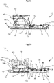
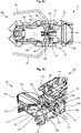
- the driving position is in the Figures 5a, 5b , 6a and 6b shown while in the rest Figures 1a to 4b the walking position is shown.
- the heel unit 100 In the driving position, the heel unit 100 is set up to engage a heel section of a ski boot in order to couple it to the heel unit 100 for a descent, whereas in the driving position the heel unit 100 is set up to release the heel section so that it can be used for can lift off the heel unit 100 on a climb.
- the heel unit 100 comprises a binding base 120.
- the binding base is in the form of a binding slide 120 which is attached to a binding plate 15 and can be displaced in the longitudinal direction of the ski.
- the binding plate 15 can be attached to a ski, in particular by means of screws.
- the heel unit 100 comprises a binding body 130 which is mounted on the binding base 120 so as to be rotatable about an axis of rotation X2 substantially perpendicular to a plane of the ski in order to adjust the heel unit 100 between the driving position and the walking position.
- this mounting consists of a radial bearing 122 formed on the binding base 120 and a complementary radial bearing 132 formed on the binding body 130, which can be formed circumferentially, but in particular are only formed in partial sections, such as in a longitudinal direction of the ski at the front and rear.
- the heel unit 100 comprises engagement means 140 protruding from the binding body 130, in particular in the form of protruding pins 140.
- the engagement means 140 occur in the driving position with a heel section of a Ski boot engaged and point in a direction forward. In the walking position, the engagement means 140 point in a direction that differs from the direction of travel. In the preferred exemplary embodiment, the engagement means 140 in the walking position point backwards in the longitudinal direction of the ski, counter to the direction of travel.
- the brake assembly 10 is adjustable between a braking position and a sliding position.
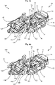
- the braking position is in the Figures 1a, 1b , 5a, 5b , 6a and 6b shown and the sliding position is in the Figures 3a, 3b and 4b shown.
- a transitional position between the braking position and the sliding position is shown.
- the braking arrangement 10 is set up to brake a ski in the event of a decoupling of touring binding and ski boot, whereas in the sliding position the braking arrangement 10 is set up not to brake the ski.
- the brake assembly 10 includes a base 20.
- the base is provided in the form of a carriage 20 which is fastened to the binding plate 15 and can be displaced in the longitudinal direction of the ski.
- the carriage 20 can be coupled to the binding carriage 120 in order to connect the brake assembly 10 and the heel unit 100 to one another.
- the brake assembly 10 further includes a pedal 30 having a tread surface 32 pointing substantially upward for a sole portion of a ski boot.
- the brake arrangement 10 also comprises at least one brake arm 40.
- two brake arms 40 designed symmetrically to a longitudinal axis of the ski are provided.
- the brake arms 40 are supported on the base 20 at middle portions thereof and supported on the pedal 30 at front portions in the longitudinal direction of the ski.
- an elastic element is provided, which the brake assembly 10 in the Braking position biases so that the brake arms 40 can engage with a surface to brake the ski.
- the elastic element can be a spring in the conventional sense, but can also be provided as an elastically yielding bracket or the like. In particular, it can act on the brake arm or arms 40 or on the pedal 30 .
- the brake assembly 10 includes a locking member 60 which is movable between an engaged position and a disengaged position.
- the locking element 60 is biased into the engaged position and in the engaged position locks the brake assembly 10 in the sliding position.
- the locking member 60 may preferably be located on an underside 34 of the pedal 30 and protrude downwardly therefrom. It can be pivoted about an axis 64 on the pedal 30 .
- the locking element 60 can be biased into the engaged position by a second elastic element 66 .
- the second elastic element 66 can be a torsion spring 66 which is coupled to the pedal 30 and the locking element 60 .
- the locking element 60 can have a hook shape, such as in Figure 1b can be seen. Such a hook 62 engages another part of the brake assembly 10 in the engaged position of the locking member 60 to lock the brake assembly 10 in the sliding position.
- the brake assembly 10 includes blocking element 70, which is adjustable between a blocking position and a release position.
- the blocking element 70 engages the locking element 60 in the sliding position of the brake assembly 10 when the locking element 60 is in the engaged position.
- the blocking element 70 does not engage the locking element 60 .
- the blocking element 70 can block the brake assembly 10 in the sliding position in its blocking position. This can be done by locking the locking element 60, in particular in the form of the hook 62 in the engagement position with a contour 74 of the blocking element 70 engages when the blocking element 70 is in the blocking position.
- the blocking element 70 can be mounted on the brake assembly 10 , in particular on the base 20 , such that it can rotate about an axis of rotation X1 that is essentially perpendicular to a plane of the ski. As a result, the blocking element 70 can move in a plane that is essentially parallel to a plane of the ski during an adjustment between the blocking position and the release position. It can also include at least one actuating section 72 and, in the preferred embodiment, includes an actuating section 72 on both sides on the left and right in the direction of the width of the ski, as for example in FIGS Figures 1a and 6a can be seen.
- the actuating sections 72 can essentially move in a transverse direction of the ski, which is perpendicular to a longitudinal direction of the ski. They can be pulled or pushed by a user to adjust the blocking element 70 . They move on a circular path due to the rotatable mounting of the blocking element, but due to a relatively large radius of this circular path compared to a width of the brake assembly 10 in the direction of the width of the ski, an almost linear movement occurs in a transverse direction of the ski.
- the operating portions 72 may be arranged outer left and right with respect to the brake assembly 10 in the ski width direction.
- the blocking element 70 as shown, inter alia, in Figure 1a can be seen to be essentially T-shaped, with the bearing being rotatable about the axis of rotation X1 being provided at a distal end section of a longitudinal bar and the two actuating sections 72 being provided on both sides at end sections of a transverse bar.
- a recess 75 can also be provided on the transverse web, into which the locking element 60 can protrude in order not to engage with the blocking element 70 when the blocking element 70 is in the release position.
- FIG. 1b A step-in function of the brake assembly 10 described above is intended below with reference to the figures 1b , 2 B and 3b be explained.
- the blocking element 70 is shown in the blocking position.
- the brake assembly 10 is moved from the braking position (see Figure 1b ) into the sliding position (see Figure 3b ), for example if a user steps on the tread 32 of the pedal 30 with his ski boot in order to move the pedal 30 and thus the locking element 60 or the hook 62 in the direction of a ski surface, an incline of the hook in the transitional position (see Figure 2b ) first on the front edge 74 on the crossbar of the blocking element 70.
- the hook 62 rotates about the axis of rotation 64 away from the crossbar. With further movement of the pedal 30 and the locking element 60 in the direction of the ski surface, the hook 62 snaps under the cross bar, returns to the engaged position due to the spring preload and thus locks the brake assembly in the sliding position (see FIG Figure 3b ).
- Figure 4a shows what happens when the blocking element 70 is placed in the release position. This is because the hook 62 then passes through the recess 75 during the above-described movement of the pedal 30 in the direction of the ski surface and can therefore not engage with the blocking element 70 .
- Figure 4b in which the blocking element 70 is shown in the blocking position, however, is closed note that the hook 62 is snapped under the cross bar 74 and is covered by it.
- the blocking element 70 and the binding body 130 are set up in such a way that the blocking element 70 cannot be brought into the blocking position in the driving position of the heel unit 100 by an interaction between the blocking element 70 and the binding body 130 .
- This can be achieved in that a lip 132 can be provided on the binding body 130 at the front in the direction of travel, which has a contact section 138, and in that an extension 76 can be provided on the blocking element 70, which has a contact section 78, with these two contact sections 78 , 138 rest against one another in the driving position of the heel unit 100 and form a common stop.
- This common stop can prevent the blocking element 70 from being displaced into the blocking position when the heel unit 100 is placed in the driving position and the lip 132 and the contact section 138 of the binding body 130 point forwards in the direction of travel. Conversely, when the heel unit 100 is in the walking position, the abutment portion 78 on the extension 78 of the blocking element 70 is spaced from the binding body 130 because the portion where the lip 132 is provided is rotated away, and the blocking element 70 can be moved to the blocking position will.
Landscapes
- Braking Arrangements (AREA)
- Footwear And Its Accessory, Manufacturing Method And Apparatuses (AREA)
Applications Claiming Priority (1)
| Application Number | Priority Date | Filing Date | Title |
|---|---|---|---|
| DE102021100316.4A DE102021100316A1 (de) | 2021-01-11 | 2021-01-11 | Bremsanordnung für eine Tourenbindung |
Publications (1)
| Publication Number | Publication Date |
|---|---|
| EP4029577A1 true EP4029577A1 (fr) | 2022-07-20 |
Family
ID=79230596
Family Applications (1)
| Application Number | Title | Priority Date | Filing Date |
|---|---|---|---|
| EP22150326.1A Pending EP4029577A1 (fr) | 2021-01-11 | 2022-01-05 | Agencement de freinage pour une fixation de randonnée |
Country Status (3)
| Country | Link |
|---|---|
| US (1) | US11998832B2 (fr) |
| EP (1) | EP4029577A1 (fr) |
| DE (1) | DE102021100316A1 (fr) |
Families Citing this family (4)
| Publication number | Priority date | Publication date | Assignee | Title |
|---|---|---|---|---|
| IT202100012872A1 (it) * | 2021-05-19 | 2022-11-19 | Atk Sports S R L | Porzione posteriore di attacco da sci alpinismo |
| USD1088157S1 (en) * | 2021-12-27 | 2025-08-12 | Rottefella As | Ski binding |
| EP4226980B1 (fr) * | 2022-02-11 | 2025-07-23 | Atk Sports S.R.L. | Butee arrière pour le ski alpinisme |
| IT202200008585A1 (it) * | 2022-04-29 | 2023-10-29 | Atk Sports S R L | Puntale di attacco da sci alpino adattato per consentire anche la camminata in salita |
Citations (3)
| Publication number | Priority date | Publication date | Assignee | Title |
|---|---|---|---|---|
| DE102013224579A1 (de) * | 2013-11-29 | 2015-06-03 | Salewa Sport Ag | Gleitbrettbindung mit vorderer Halteeinrichtung und Bremseinrichtung |
| EP3409332A1 (fr) * | 2017-05-29 | 2018-12-05 | Felisaz SAS | Dispositif arriere de fixation de ski de randonnee a dispositif de verrouillage de frein de ski |
| EP3750604A1 (fr) * | 2019-06-11 | 2020-12-16 | Elan, d.o.o. | Frein de fixation de ski alpin |
Family Cites Families (4)
| Publication number | Priority date | Publication date | Assignee | Title |
|---|---|---|---|---|
| DE102012214001B4 (de) * | 2012-08-07 | 2014-03-13 | Marker Deutschland Gmbh | Skibremse mit Verriegelung |
| DE102013224571B4 (de) | 2013-11-29 | 2020-03-26 | Salewa Sport Ag | Ferseneinheit mit Bremsanordnung |
| DE102017120688A1 (de) | 2017-09-07 | 2019-03-07 | Marker Deutschland Gmbh | Bindung mit Sicherungselement für Skibremse |
| IT202100012872A1 (it) * | 2021-05-19 | 2022-11-19 | Atk Sports S R L | Porzione posteriore di attacco da sci alpinismo |
-
2021
- 2021-01-11 DE DE102021100316.4A patent/DE102021100316A1/de active Pending
-
2022
- 2022-01-05 EP EP22150326.1A patent/EP4029577A1/fr active Pending
- 2022-01-10 US US17/571,876 patent/US11998832B2/en active Active
Patent Citations (3)
| Publication number | Priority date | Publication date | Assignee | Title |
|---|---|---|---|---|
| DE102013224579A1 (de) * | 2013-11-29 | 2015-06-03 | Salewa Sport Ag | Gleitbrettbindung mit vorderer Halteeinrichtung und Bremseinrichtung |
| EP3409332A1 (fr) * | 2017-05-29 | 2018-12-05 | Felisaz SAS | Dispositif arriere de fixation de ski de randonnee a dispositif de verrouillage de frein de ski |
| EP3750604A1 (fr) * | 2019-06-11 | 2020-12-16 | Elan, d.o.o. | Frein de fixation de ski alpin |
Also Published As
| Publication number | Publication date |
|---|---|
| DE102021100316A1 (de) | 2022-07-14 |
| US20220219069A1 (en) | 2022-07-14 |
| US11998832B2 (en) | 2024-06-04 |
Similar Documents
| Publication | Publication Date | Title |
|---|---|---|
| EP4029577A1 (fr) | Agencement de freinage pour une fixation de randonnée | |
| DE102012201816B4 (de) | Vordereinheit für eine Gleitbrettbindung mit ersten und zweiten Eingriffsmitteln | |
| DE69513301T2 (de) | Snowboardbindung | |
| EP0551899B1 (fr) | Fixation de ski de fond ou de ski de randonnée pour des chaussures de ski de fond | |
| DE69630244T2 (de) | Snowboardstiefel und bindung | |
| DE19816697C2 (de) | Stiefel zum Eingriff mit einer an einem Gegenstand zum Gleiten auf Schnee befestigten Bindung | |
| DE69607454T2 (de) | Skischuhbindungssystem für Snowboards | |
| DE102012208915B4 (de) | Ferseneinheit mit Steighilfe und Bremsanordnung | |
| DE9421380U1 (de) | Snowboardbindung | |
| DE19635250A1 (de) | Automatische Befestigungsvorrichtung | |
| EP3974039A1 (fr) | Agencement de freinage pour une fixation de randonnée | |
| EP2695647B1 (fr) | Frein pour ski avec verrouillage | |
| AT171U1 (de) | Kombination, bestehend aus einem snowboardschuh und einer snowboardbindung | |
| DE60203240T2 (de) | Bindungsträgerplatte für ein Snowboard | |
| AT522136B1 (de) | Vordereinheit für eine Gleitbrettbindung | |
| AT524641B1 (de) | Bremsanordnung für eine Gleitbrettbindung | |
| DE29722787U1 (de) | Rollschuh mit arretierbarer Bremse | |
| DE19846005C1 (de) | Stiefel-Bindungskombination | |
| AT412949B (de) | Langlaufbindung | |
| AT405372B (de) | Snowboardbindung | |
| EP3714952A1 (fr) | Dispositif de freinage | |
| EP2821114A1 (fr) | Système de fixation de sécurité | |
| EP3851173B1 (fr) | Talon à blocage en rotation pour une fixation de ski randonnée | |
| DE69200966T2 (de) | Skibremse. | |
| DE102024129166A1 (de) | Ferseneinheit für eine Gleitbrettbindung |
Legal Events
| Date | Code | Title | Description |
|---|---|---|---|
| PUAI | Public reference made under article 153(3) epc to a published international application that has entered the european phase |
Free format text: ORIGINAL CODE: 0009012 |
|
| STAA | Information on the status of an ep patent application or granted ep patent |
Free format text: STATUS: THE APPLICATION HAS BEEN PUBLISHED |
|
| AK | Designated contracting states |
Kind code of ref document: A1 Designated state(s): AL AT BE BG CH CY CZ DE DK EE ES FI FR GB GR HR HU IE IS IT LI LT LU LV MC MK MT NL NO PL PT RO RS SE SI SK SM TR |
|
| STAA | Information on the status of an ep patent application or granted ep patent |
Free format text: STATUS: REQUEST FOR EXAMINATION WAS MADE |
|
| 17P | Request for examination filed |
Effective date: 20221207 |
|
| RBV | Designated contracting states (corrected) |
Designated state(s): AL AT BE BG CH CY CZ DE DK EE ES FI FR GB GR HR HU IE IS IT LI LT LU LV MC MK MT NL NO PL PT RO RS SE SI SK SM TR |
|
| STAA | Information on the status of an ep patent application or granted ep patent |
Free format text: STATUS: EXAMINATION IS IN PROGRESS |
|
| 17Q | First examination report despatched |
Effective date: 20240919 |