EP4031254B1 - Abschaltbare abstiegskontrollsysteme und -vorrichtungen - Google Patents
Abschaltbare abstiegskontrollsysteme und -vorrichtungen Download PDFInfo
- Publication number
- EP4031254B1 EP4031254B1 EP20797240.7A EP20797240A EP4031254B1 EP 4031254 B1 EP4031254 B1 EP 4031254B1 EP 20797240 A EP20797240 A EP 20797240A EP 4031254 B1 EP4031254 B1 EP 4031254B1
- Authority
- EP
- European Patent Office
- Prior art keywords
- braking system
- shaft
- descent
- line
- coupled
- Prior art date
- Legal status (The legal status is an assumption and is not a legal conclusion. Google has not performed a legal analysis and makes no representation as to the accuracy of the status listed.)
- Active
Links
Images












Classifications
-
- A—HUMAN NECESSITIES
- A62—LIFE-SAVING; FIRE-FIGHTING
- A62B—DEVICES, APPARATUS OR METHODS FOR LIFE-SAVING
- A62B1/00—Devices for lowering persons from buildings or the like
- A62B1/06—Devices for lowering persons from buildings or the like by making use of rope-lowering devices
- A62B1/08—Devices for lowering persons from buildings or the like by making use of rope-lowering devices with brake mechanisms for the winches or pulleys
- A62B1/10—Devices for lowering persons from buildings or the like by making use of rope-lowering devices with brake mechanisms for the winches or pulleys mechanically operated
-
- A—HUMAN NECESSITIES
- A62—LIFE-SAVING; FIRE-FIGHTING
- A62B—DEVICES, APPARATUS OR METHODS FOR LIFE-SAVING
- A62B1/00—Devices for lowering persons from buildings or the like
- A62B1/06—Devices for lowering persons from buildings or the like by making use of rope-lowering devices
- A62B1/08—Devices for lowering persons from buildings or the like by making use of rope-lowering devices with brake mechanisms for the winches or pulleys
-
- F—MECHANICAL ENGINEERING; LIGHTING; HEATING; WEAPONS; BLASTING
- F16—ENGINEERING ELEMENTS AND UNITS; GENERAL MEASURES FOR PRODUCING AND MAINTAINING EFFECTIVE FUNCTIONING OF MACHINES OR INSTALLATIONS; THERMAL INSULATION IN GENERAL
- F16D—COUPLINGS FOR TRANSMITTING ROTATION; CLUTCHES; BRAKES
- F16D59/00—Self-acting brakes, e.g. coming into operation at a predetermined speed
-
- F—MECHANICAL ENGINEERING; LIGHTING; HEATING; WEAPONS; BLASTING
- F16—ENGINEERING ELEMENTS AND UNITS; GENERAL MEASURES FOR PRODUCING AND MAINTAINING EFFECTIVE FUNCTIONING OF MACHINES OR INSTALLATIONS; THERMAL INSULATION IN GENERAL
- F16D—COUPLINGS FOR TRANSMITTING ROTATION; CLUTCHES; BRAKES
- F16D63/00—Brakes not otherwise provided for; Brakes combining more than one of the types of groups F16D49/00 - F16D61/00
- F16D63/002—Brakes with direct electrical or electro-magnetic actuation
-
- H—ELECTRICITY
- H02—GENERATION; CONVERSION OR DISTRIBUTION OF ELECTRIC POWER
- H02K—DYNAMO-ELECTRIC MACHINES
- H02K49/00—Dynamo-electric clutches; Dynamo-electric brakes
- H02K49/02—Dynamo-electric clutches; Dynamo-electric brakes of the asynchronous induction type
- H02K49/04—Dynamo-electric clutches; Dynamo-electric brakes of the asynchronous induction type of the eddy-current hysteresis type
- H02K49/046—Dynamo-electric clutches; Dynamo-electric brakes of the asynchronous induction type of the eddy-current hysteresis type with an axial airgap
-
- F—MECHANICAL ENGINEERING; LIGHTING; HEATING; WEAPONS; BLASTING
- F16—ENGINEERING ELEMENTS AND UNITS; GENERAL MEASURES FOR PRODUCING AND MAINTAINING EFFECTIVE FUNCTIONING OF MACHINES OR INSTALLATIONS; THERMAL INSULATION IN GENERAL
- F16D—COUPLINGS FOR TRANSMITTING ROTATION; CLUTCHES; BRAKES
- F16D2121/00—Type of actuator operation force
- F16D2121/18—Electric or magnetic
- F16D2121/20—Electric or magnetic using electromagnets
-
- F—MECHANICAL ENGINEERING; LIGHTING; HEATING; WEAPONS; BLASTING
- F16—ENGINEERING ELEMENTS AND UNITS; GENERAL MEASURES FOR PRODUCING AND MAINTAINING EFFECTIVE FUNCTIONING OF MACHINES OR INSTALLATIONS; THERMAL INSULATION IN GENERAL
- F16D—COUPLINGS FOR TRANSMITTING ROTATION; CLUTCHES; BRAKES
- F16D49/00—Brakes with a braking member co-operating with the periphery of a drum, wheel-rim, or the like
- F16D49/08—Brakes with a braking member co-operating with the periphery of a drum, wheel-rim, or the like shaped as an encircling band extending over approximately 360 degrees
-
- F—MECHANICAL ENGINEERING; LIGHTING; HEATING; WEAPONS; BLASTING
- F16—ENGINEERING ELEMENTS AND UNITS; GENERAL MEASURES FOR PRODUCING AND MAINTAINING EFFECTIVE FUNCTIONING OF MACHINES OR INSTALLATIONS; THERMAL INSULATION IN GENERAL
- F16D—COUPLINGS FOR TRANSMITTING ROTATION; CLUTCHES; BRAKES
- F16D55/00—Brakes with substantially-radial braking surfaces pressed together in axial direction, e.g. disc brakes
- F16D55/02—Brakes with substantially-radial braking surfaces pressed together in axial direction, e.g. disc brakes with axially-movable discs or pads pressed against axially-located rotating members
-
- F—MECHANICAL ENGINEERING; LIGHTING; HEATING; WEAPONS; BLASTING
- F16—ENGINEERING ELEMENTS AND UNITS; GENERAL MEASURES FOR PRODUCING AND MAINTAINING EFFECTIVE FUNCTIONING OF MACHINES OR INSTALLATIONS; THERMAL INSULATION IN GENERAL
- F16D—COUPLINGS FOR TRANSMITTING ROTATION; CLUTCHES; BRAKES
- F16D55/00—Brakes with substantially-radial braking surfaces pressed together in axial direction, e.g. disc brakes
- F16D55/02—Brakes with substantially-radial braking surfaces pressed together in axial direction, e.g. disc brakes with axially-movable discs or pads pressed against axially-located rotating members
- F16D55/22—Brakes with substantially-radial braking surfaces pressed together in axial direction, e.g. disc brakes with axially-movable discs or pads pressed against axially-located rotating members by clamping an axially-located rotating disc between movable braking members, e.g. movable brake discs or brake pads
- F16D55/224—Brakes with substantially-radial braking surfaces pressed together in axial direction, e.g. disc brakes with axially-movable discs or pads pressed against axially-located rotating members by clamping an axially-located rotating disc between movable braking members, e.g. movable brake discs or brake pads with a common actuating member for the braking members
- F16D55/225—Brakes with substantially-radial braking surfaces pressed together in axial direction, e.g. disc brakes with axially-movable discs or pads pressed against axially-located rotating members by clamping an axially-located rotating disc between movable braking members, e.g. movable brake discs or brake pads with a common actuating member for the braking members the braking members being brake pads
-
- F—MECHANICAL ENGINEERING; LIGHTING; HEATING; WEAPONS; BLASTING
- F16—ENGINEERING ELEMENTS AND UNITS; GENERAL MEASURES FOR PRODUCING AND MAINTAINING EFFECTIVE FUNCTIONING OF MACHINES OR INSTALLATIONS; THERMAL INSULATION IN GENERAL
- F16D—COUPLINGS FOR TRANSMITTING ROTATION; CLUTCHES; BRAKES
- F16D63/00—Brakes not otherwise provided for; Brakes combining more than one of the types of groups F16D49/00 - F16D61/00
- F16D63/008—Brakes acting on a linearly moving member
Definitions
- Climbing typically uses a two-person manual system, a climber and a belayer, attached together with a rope.
- the rope is attached on one end to the climber, extends to the top of a climbing route through a top anchor, and comes down to the belayer.
- the belayer feeds the rope through a belay device and can catch the climber when they fall. Once the climber gets to the top of the climbing route, the climber loads the rope and transfers the weight to the belayer and the belay device. The belay er can then lower the climber by feeding the rope back through the belay device.
- This system allows the climber to stop at any location on the climbing route, transfer their weight to the rope, and the belay er can hold the climber mid-route. This allows the climber to rest or the time to try difficult moves repeatedly without being lowered all the way down to the ground. The method is known as "lock- off' or "hangdogging.”
- Some known climbing systems can automatically protect a climber from falls without the use of the belayer.
- Line dispensing devices such as auto-belay devices used for climbing, retract slack when the rope is not under load (e.g., when the climber is climbing) and provides a braking force when the rope is loaded (e.g., when the climber falls) so that the climber on the end of the rope is lowered to the ground.
- Auto belay devices cannot lock-off and allow the climber to rest or hangdog mid route.
- This disclosure describes examples of automatic descent control systems and descent devices (e.g., auto-belay devices) that are operable to automatically lower a climber at a first descent rate upon loading the descent device and to selectively lower the climber at a different second descent rate upon loading the descent device.
- the first descent rate is greater than the second descent rate so that with the second descent rate the climber is allowed to hang above a ground surface without being lowered all the way to the ground surface as required or desired.
- the control systems and descent devices can be implemented in any number of descent control technologies including fan braking systems, friction braking system, hydraulic braking systems, magnetic braking systems, etc. as described herein.
- the technology relates to an automatic descent control device including: a housing; a shaft rotatably supported within the housing; a line configured to be attached to a load, wherein the line is coupled to the shaft, and wherein the line retracts within the housing and winds about the shaft when the line is not loaded, and extends from the housing and unwinds about the shaft when the line is loaded; an eddy current braking system coupled to the shaft, wherein the eddy current braking system provides a first braking force to the shaft when the line is loaded, and wherein the eddy current braking system lowers the load at a first descent rate; a second braking system coupled to the shaft, wherein the second braking system provides a second braking force to the shaft when the line is loaded, wherein the second braking system lowers the load at a second descent rate, and wherein the load is a constant, and the first descent rate is greater than the second descent rate; and a controller coupled to the second braking system, wherein the controller selectively engages the second braking system upon receiving
- the eddy current braking system includes a brake shaft rotatably coupled to the shaft, at least one conductor, and at least one magnet, and wherein the first braking force is generated by rotation of the brake shaft inducing centrifugal forces into the at least one conductor or the at least one magnet such that the at least one conductor or the at least one magnet is moved relative to the other.
- the brake shaft is offset from the shaft, and the brake shaft is coupled to the shaft via by one or more gears.
- the brake shaft is configured to rotate at a different speed than the shaft.
- the rotor is configured to rotate at the same speed of the shaft.
- a sensor configured to detect when the line is loaded and send an actuation signal to the controller, and the controller selectively actuates the second braking system upon receiving the actuation signal.
- the senor includes one or more of an encoder, an accelerometer, a force gauge, a strain gauge, and a laser sensor.
- an engagement button configured to generate the engagement signal, and the engagement button is remote from the housing.
- the second braking system is an electromagnetic braking system.
- the second braking system includes the disk braking system, and the disk braking system includes a rotor coupled to the shaft and at least one caliper supported on the housing.
- the second braking system includes the electromagnetic braking system, and the electromagnetic braking system includes a rotor coupled to the shaft and an electromagnet supported on the housing.
- the automatic descent control device automatically operates in the first braking system unless the second braking system is engaged. In another example, upon engagement of the second configuration via the engagement device, the controller automatically disengages the second configuration after a predetermined time period.
- the sensor device is remote from the descent device. In still another example, the sensor device monitors a position of the load. In an example, the sensor device monitors a condition of the descent device.
- the engagement device is remote from the descent device. In yet another example, the engagement device is sized and shaped as a rock climbing hold.
- the second descent rate locks the position of the line and prevent the load from lowering.
- the first braking system includes a series of pulleys that the line extends through.
- the braking force is based on a speed of the line passing through the at least one braking system.
- the first braking system is an eddy current braking system and the second braking system is an electromechanical braking system.
- the electromechanically braking system includes: a plug shaft configured to couple to the shaft; a clutch bearing coupled to the plug shaft; a brake hub coupled to the clutch bearing, the plug shaft, the clutch bearing, and the brake hub are all co-axial and all rotatably driven by the shaft; a clamp wheel coupled to the housing; and a brake pad coupled to the clamp wheel.
- the clamp wheel includes an electric coil configured to generate a magnetic field.
- the electromechanically braking system includes: a reluctor wheel; and a sensor, the sensor is configured to measure rotational speed and direction of the shaft via the reluctor wheel.
- a remote interface hold is coupled in communication with the descent control device, the interface hold includes a power source configured to provide power to the electromagnetic braking system.
- the technology in another aspect, relates to a secondary braking system for an automatic descent control device configured to generate a first braking force relative to a rotatable shaft, the secondary braking system including: a plug shaft configured to couple to the rotatable shaft of the automatic descent control device and rotation driven therefrom; a rotor assembly coupled to the plug shaft; and a stator assembly fixed relative to the rotary assembly, wherein the rotor assembly and stator assembly are configured to generate a second braking force relative to the shaft through the plug shaft.
- the second braking force is friction based.
- the rotor assembly includes: a clutch bearing coupled to the plug shaft; and a brake hub coupled to the clutch bearing, the plug shaft, the clutch bearing, and the brake hub are all co-axial and all rotatably driven by the rotatable shaft.
- the stator assembly includes: a clamp wheel coupled to the housing; and a brake pad coupled to the clamp wheel.
- a controller is configured to selectively engage the second braking force, the controller is configured to measure rotational speed and direction of the rotatable shaft via a reluctor wheel.
- This disclosure describes examples of automatic descent control systems and descent devices that are operable in two different configurations.
- the system and devices In a first and normal operational configuration, automatically lower a climber at a first descent rate upon loading the descent device.
- loading the descent device includes the climber falling or transferring at least a portion of weight to the descent device.
- the system and devices are selectively operable in a second and lock-off operational configuration, whereby the climber is lowered at a second descent rate upon loading the descent device.
- the first descent rate is greater than the second descent rate so that in the lock-off operational configuration the climber is allowed to hang above a ground surface without being lowered all the way to the ground surface.
- the descent control systems described herein includes a descent device with a braking system that is operable in both the normal operational configuration and the lock-off operational configuration.
- An engagement device is used to selectively engage the lock-off operational configuration of the braking system.
- This engagement device can be remote from the descent device, for example, a button on a climbing wall or part of a control station that operationally monitors one or more features of the climbing wall.
- a sensor device is provided so that the loading of the descent device can be detected and the braking system engaged so as to generate a braking force for the second descent rate.
- This sensor device can monitor any number of components of the descent control system, for example movement of the descent device, the braking system itself, or a position of the climber. As such, the engagement device can be actively engaged by the climber or automatically engaged requiring no action by the climber.
- the descent devices e.g., auto belay devices
- the descent devices can either include a single braking system that can change operational configurations or have two separate braking systems, one for each operational configuration.
- existing descent devices such as fan braking systems, friction braking systems, hydraulic braking systems, electromagnetic braking systems, and magnetic braking systems, can be adapted to allow the climber to hang above the ground surface in the lock-off operational configuration.
- references to orientation (e.g., front(ward), rear(ward), top, bottom, back, right, left, upper, lower, etc.) of the descent device relate to its position when installed on a climbing wall and are used for ease of description and illustration only. No restriction is intended by use of the terms regardless of how the descent device is situated on its own.
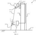
- FIG. 1 is a schematic view of an exemplary automatic descent control system 100.
- the system 100 includes a climbing wall 102 and a descent device 104 positioned at the top of the climbing wall 102.
- the climbing wall 102 is an indoor wall having a height H above a ground surface 106 and a plurality of climbing holds (not shown) so that a climber 108 can climb up the wall 102 and above the ground surface 106 as desired.
- any of the components of the system 100 may be used in outdoor climbing walls, for example, artificial walls, natural walls, mobile walls, etc., challenge courses, for example, an obstacle course, a ropes course, etc., training or work based activities, for example, search and rescue, fire department, construction, etc., safety systems, or any other actively that requires or desires descending from a height above a ground surface.
- the descent device 104 includes a line 110 configured to be attached to the climber 108 (e.g., a load).
- the term "line” refers to any cable, rope, string, chain, wire, webbing, strap, or any other length of flexible material.
- the line 110 is enabled to retract within the descent device 104 when the line 110 is not loaded. For example, when the climber 108 is moving up the wall 102 so that the slack in the line 110 is removed.
- the line 110 is also enabled to extend from the descent device 104 when the line 110 is loaded. For example, when the climber 108 falls from the wall 102 and the climber's weight is transferred from the wall 102 to the line 110.
- the descent device 104 has a braking system (not shown) that applies a braking force to the line 110 when the line is loaded so as to control the extension of the line 110 and a descent rate of the climber 108.
- the descent device 104 can have a fan braking system, a friction braking system, a hydraulic braking system, an electromagnetic braking system, a magnetic braking system, or any other braking system as required or desired. Different types of descent devices 104 are described further below in FIGS. 6-15 .
- the descent device 104 may be a device that the line 110 passes through and applies a braking force on the line 110 so as to control the rate that the line 110 passes through, and thus, a descent rate of the climber 108.
- these devices can be climb assist pulleys that at low speeds (e.g., the climber climbing and the line unloaded) allows the line 110 to freely pass through the braking system and at increased speeds (e.g., the climber falling and loading the line) the braking system locks the line 110.
- These types of devices typically have a friction braking system such as a series of pulleys that engage with the line 110, or use a mechanical advantage with a camming mechanism.
- the descent device 104 also has a second or lock-off operational configuration, in which when the climber 108 falls from the wall 102, the line 110 is restricted from extending so that the climber 108 is held in position on the wall 102 and above the ground surface 106 by the descent device 104.
- This configuration allows the climber 108 to rest and try difficult moves repeatedly above the ground surface 106 without being required to descend all the way to the ground as typical of the normal operational configuration.
- a normal descent rate can be between about 0.5 meters/second and 4 meters/second. This type of descent rate typically results in the climber 108 being lowered all the way to the ground surface 106 after falling from the wall.
- the climber 108 is lowered at a second or lock-off descent rate.
- a lock-off descent rate can be between about 0 meters/second and 0.3 meters/second. In some example, the lock-off descent rate may physically stop the climber 108 and prevent descent down the wall 102 (e.g., 0 meters/seconds).
- the lock-off descent rate may significantly slow down the climber's descent down the wall 102 compared to the normal descent rate and allow for the climber 108 to rest and climb back on the wall 102. In either example, the normal descent rate is greater than the lock-off descent rate for the same climber load.
- the descent device 104 can switch between the normal operational configuration and the lock-off operational configuration as required or desired.
- the switch between the different configurations can be actively induced by the climber 108 or automatically within the device 104 (e.g., passive from the climber 108).
- an engagement device 112 is disposed remote from and coupled in communication with a controller 114 of the descent device 104.
- the controller 114 is configured to switch the descent device 104 between the normal operational configuration and the lock-off operational configuration.
- the descent device 104 when the engagement device 112 is engaged, the descent device 104 operates in the lock-off operational configuration. Otherwise the engagement device 112 is disengaged so that the descent device 104 operates in the normal operational configuration as a default configuration.
- the engagement device 112 may be a button located on the bottom of the wall 102 so that the climber can elect to engage the lock-off operational configuration when climbing alone.
- the lock-off operational configuration is disengageable (e.g., actively or passively) so that the climber 108 can be lowered all the way to the ground surface 106 and not remained locked-off on the wall.
- Passive disengagement e.g., from the climbers 108 perspective
- the controller 114 e.g., either a mechanical or electronic controller.
- the climber 108 falling from the wall 102 can start a mechanical clock (not shown) that includes springs and gears, which after a predetermined time period would trigger disengagement of the lock-off operational configuration.
- the mechanical clock could be an hourglass or a water clock (e.g., movement of fluid, gas, or solid through a constriction) that is configured to a predetermined time period.
- the timer can be a mechanical device such as a cam lobe, spring, or a gas shock.
- the descent device 104 may have an electronic timer (e.g., on the controller 114) that automatically disengages the lock-off operational configuration upon a predetermined time period or condition that is satisfied so that the climber 108 can lower all the way to the ground surface 106.
- the descent device 104 may automatically switch to the normal operational configuration and lower the climber 108 towards the ground surface 106.
- the subsequent lock-off operation will automatically switch the descent device 104 to the normal operational configuration and lower the climber 108 towards the ground surface 106.
- the climber 108 may climb without another person (e.g., a belayer) present.
- the engagement device 112 may be sized and shaped as a rock climbing hold for use by the climber 108.
- the engagement device 112 can be a switch, an adjustable controller, a computer interface, a touch sensitive area, a biometric sensor, a mobile application, a sound sensor, etc.
- a position sensor disposed on the wall 102 and above the ground surface 106 e.g., around six feet may be used to detect a position of the climber 108 on the wall 102 and automatically engage the lock-off operational configuration once the climber 108 reaches a predetermined height.
- the engagement device 112 can be a scanner that reads information off of a RFID tag, bar code, QR code, or other code based information and relay the information to the descent device 104.
- the code may engage the lock-off operational configuration and specify the time period for lock-off or specify three sequential lock-off operations by the climber 108 so that after the condition is satisfied the descent device 104 switches to the normal operational configuration.
- the engagement device 112 may be positioned within the descent device 104 and include a sensor that can detect a specific series of patterns from the climber 108 pulling on the line 110. For example, when the climber 108 pulls down on the line 110 three times in quick succession, the engagement device 112 may engage the lock-off operational configuration.
- the engagement device 112 can be other system/method that allows the climber 108 to selectively engage the lock-off operational configuration as required or desired.
- the engagement device 112 may be a remote switch that the climber 108 can carry during use.
- the automatic descent control system 100 may also include one or more secondary engagement devices 116 coupled in communication with the controller 114.
- a button may be disposed at the top of the wall 102 so that when the climber 108 completes the route, the lock-off operational configuration can actively be disengaged and the climber 108 can be lowered all the way to the ground surface 106.
- the lock-off operation configuration may be the default configuration and the engagement device 112 switches the descent device 104 to the normal operational configuration.
- the engagement device 112 is disposed at the top of the wall 102 so as to enable the climber 108 to engage the normal operational configuration of the descent device 104 and lower all the way to the ground surface 106.
- the descent device 104 has a braking system (not shown) that controls the descent rate of the climber 108 in both operational configurations.
- the same braking system may be used in both operational configurations, while in other examples, each operational configuration may have its own independent braking system. Braking systems are described further below in reference to FIGS. 6-13 .
- a sensor device 118 that is coupled in communication to the controller 114 is utilized. The sensor device 118 detects one or more operational configurations of the line 110 being loaded (e.g., the climber 108 falling off the wall) so as to actuate the braking system.
- the sensor device 118 is disposed within the descent device 104 so that a condition of the descent device 104 is monitored.
- the sensor device 118 can be a rotatory encoder to measure whether the line 110 is extending or retracting from the housing and at what velocity and/or acceleration.
- an accelerometer, force sensor, strain gauge, velocity sensor, laser sensor, LIDAR sensor, sonar, camera, etc. can be used as required or desired.
- the sensor device 118 can be remote from the descent device 104.
- one or more sensor devices 118 can be placed on the wall 102 and/or the ground surface 106 and be used to monitor the position and movement of the climber 108 so if a fall occurs, the braking system can be actuated.
- the sensor device 118 can be a camera pointed at the entire wall system to monitor the position and movement of the climber 108 and actuate the braking system as required or desired.
- the sensor device 118 can be placed on/in the line 110, the hold features on the wall 102, along the route of the climber 108, or on the wall 102 itself.
- the sensor device 118 may be a button located on the wall 102 or remote from the wall 102 that a belayer presses to actuate the braking system as required or desired.
- the controller 114 can be connected to the engagement device(s) 112, 116 and/or the sensor device(s) 118 in a wired communication network. In other examples, the controller 114 is connected to the engagement device(s) 112, 116 and/or the sensor device(s) 118 in a wireless communication network. Wireless communication can include infrared, BLUETOOTH ® wireless technology, 802.11a/b/g/n, cellular, or other radio frequency communication systems as required or desired.
- the controller 114 operates to receive data from the engagement device(s) 112, 116 and the sensor device(s) 118 about user inputs or selections for controlling the descent device 104 (e.g., engaging a specific configuration and actuating the brake).
- the controller 114 can also operate to transmit data regarding the descent device 104 as required or desired.
- the controller 114 is an electronic controller that electronically engages and actuates the braking system. For example, by electrically actuating a servo, a motor, etc. so as to engage the lock-off operational configuration and actuate the braking system to generate a braking force.
- the controller 114 can be a mechanical controller that mechanically engages and actuates the braking system.
- a power screw, lead screw, worm gear, rack and pinion, ratchet, pawls, spring clutch, flyball governor, inertial governor, counterweight, resistance, spring(s), clock spring, diaphragm, Belleville washer, torsion bar, leaf spring, coil spring, gas shock, etc. so as to engage the lock-off operational configuration and actuate the braking system to generate a braking force.
- FIG. 2 is a schematic view of another automatic descent control system 200. Similar to the example described above, the system 200 includes a climbing wall 102 and a descent device 104 having a line 110 attached to a climber 108. In this example, however, the descent device 104 is coupled in communication 202 (e.g., wired or wireless) to a control station 204.
- the control station 204 is remote from the wall 102 and, in some examples, can be a computing device used to implement aspects of the systems and methods described herein.
- the control station 204 enables a user (e.g., the belayer) to transmit control signals to the descent device 104. For example, the user can engage or disengage the lock-off operational configuration (described above) as required or desired.
- the control station 204 can be coupled in communication to a plurality of descent devices 104 (e.g., on a synthetic climbing wall) so that a single user can controller multiple descent devices 104 for multiple climbers 108.
- the control station 204 can be coupled to remotely located sensor devices 118 (shown in FIG. 1 ) that monitor the climber 108.
- the control station 204 can also transmit actuation signals to the braking system.
- a multi-camera projection system can monitor the climbing wall 102 and be used to detect the position of the climbers 108 for actuation of the braking system.
- the computing devices includes processing device(s) and system memory.
- Examples of computing devices includes a desktop computer, a laptop computer, a tablet computer, a mobile device including a smart phone, or any other devices configured to process digital instructions.
- the computing device can include input devices, such as a keyboard, a pointer, microphone, a touch sensitive display, etc., to enable a user to provide inputs to the computing device.
- FIG. 3 is a schematic view of another automatic descent control system 300.
- a descent device 302 includes a first line 304 and a second line 306 in parallel. Both lines 304, 306 are attached to the climber 108 and used for when the climber 108 climbs the wall 102.
- the first line 304 operates only in the normal operational configuration, while the second line 306 operates only in the lock-off operational configuration.
- This allows for two separate braking systems to be used (e.g., one for each line 304, 306) and for the lock-off operational configuration to be engaged/disengaged as required or desired. By separating the braking systems, a redundant system is formed.
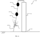
- FIG. 4 is a schematic view of another automatic descent control system 400.
- a first descent device 402 has a first line 404 that is coupled to a second descent device 406.
- the second descent device 406 has a second line 408 that is coupled to the climber 108.
- the two descent devices 402, 406 are coupled in series and have different braking characteristics (e.g., different descent rates) so that staged braking is provided when the climber 108 falls from the wall 102 and a lock-off operational configuration is enabled.
- the first descent device 402 can be replaced by an actuator (e.g., electric motor, solenoid, screw jack, etc.) that extends and retracts the line 404, and thus the second descent device 406, to the ground surface. This configuration enables the second descent device 406 to have the lock-off operational configuration in any loading scenario.
- the actuator is used to lower the climber to the ground.
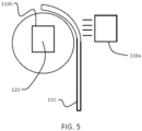
- FIG. 5 is a schematic view of the sensor device 118 for use with the automatic descent control system 100 (shown in FIG. 1 ).
- the sensor device 118a can be disposed within the descent device 104 and is configured to detect one or more operational configurations of the line 110 being loaded (e.g., the climber falling off the wall) so as to actuate the braking system.
- the sensor device 118a can monitor the movement of the line 110.
- the movement can be a position and/or direction of the movement so that velocity and acceleration can be determined.
- the line may include features (e.g., metal strands, flags, RFID chips, etc.) to assist with the sensor monitoring.
- the sensor device 118b may be positioned on a rotor 120 and configured to detect one or more operational configuration of the rotor 120 being loaded so as to actuate the braking system.
- the sensor device 118b can monitor rotational movement of one or more components of the descent device 104.
- the movement can be a position and/or direction of the movement so that velocity and acceleration can be determined, for example, with a rotary encoder.
- the rotor 120 can be a roller that the line 110 passes over as illustrated. In other examples, the rotor 120 can be the drum that the line 110 winds about. Additionally or alternatively, the sensor device 118 can monitor components of the braking system.
- the sensor device 118 can also be disposed remote from the descent device 104.
- one or more sensor devices 118 can be placed on the wall 102 (e.g., as holds on the climbing route) and/or the ground surface 106 and be used to monitor the position and movement of the climber 108.
- the sensor device 118 can be a camera pointed at the entire wall system to monitor the position and movement of the climber 108 (e.g., via the control station 204 (shown in FIG. 2 )).
- the sensor device 118 may be a button located on the wall 102 or remote from the wall 102 that a belayer presses to actuate the braking system as required or desired.
- the normal operational configuration typically automatically generates a braking force
- the lock-off operational configuration needs to be able to selectively engage and disengage, and thus, requires the sensor device 118 to trigger a braking force to be generated. It should be appreciated that this sequence of operation can also be reversed or that both operational configurations use the sensor device 118 to trigger a braking force to be generated.
- FIG. 6 is a schematic view of an exemplary automatic descent control device 500 for use with the automatic descent control systems described above.
- the descent device 500 includes a line system 502 that retracts slack from a line 504 when the line is not loaded and that extends the line 504 when the line is loaded (e.g., upon a fall from a climber).
- the line system 502 includes a rotatable shaft 506 and a drum 508 that the line 504 wraps around.
- the descent device 500 also includes a first braking system 510 that provides a braking force when the line 504 is loaded so as to control extension of the line 504 and defines a first descent rate of a load (e.g., the climber).
- the first braking system 510 is an automatic fan braking system and includes a plurality of fan blades 512.
- a working fluid e.g., air
- a braking force is generated to slow the rotation of the shaft 506, and thus, the extension of the line 504.
- a second braking system 514 is coupled to one or more components of the first braking system 510 (e.g., the shaft 506) and also provides a braking force to the shaft 506 so as to control extension of the line 504 and define a second descent rate of the load.
- the second braking system 514 is a disk braking system 516 with a rotor 518 coupled to the shaft 506 and at least one caliper 520 configured to engage with the rotor 518 to generate the braking force.
- the first braking system 510 enables the descent device 500 to operate in the normal operational configuration. Because the fan blades 512 are coupled to the shaft 506, the first braking system 510 is always operational when the shaft 506 rotates.
- the second braking system 514 is selectively operable so that the descent device 500 can operate in the lock-off operational configuration.
- the descent device 500 has at least two different configurations for two different descent rates of the same constant load (e.g., the climber).
- the disk braking system 516 can lock the position of the shaft 506, and thus the line 504, so as to prevent the climber from lowering to the ground. Additionally, the disk braking system 516 can slowly lower the line 504 as required or desired.
- the descent device 500 automatically switches to the first braking system 510 so that the normal operational configuration is engaged. Furthermore, by using two separate braking systems, redundant braking systems are provided and the number of possible fail points of the descent device 500 are reduced.
- the second braking system 514 could be any other rotational brake device as required or desired.
- a band brake wrapped around any rotating component e.g., the shaft 506
- a drum brake engaged with the drum 508 or the shaft 506 could be used.
- a pin lock can also be used, with a rotating element coupled to the shaft 506 having pre-loaded pins that selectively engage (e.g., by a timing device) with a static element to prevent rotation of the system.
- the braking system 514 could interact with the fan blades 512 to prevent rotation of the shaft 506. For example, by a band brake or by a disk brake with the tips of the blades being coupled together with a rotor element.
- the second braking system 514 may be an electromagnetic brake.
- the second braking system 514 could also be another fan type braking system.
- the controller 114 (shown in FIG. 1 ) of the descent device 500 is used to engage and disengage the second braking system 514 as described above.
- the second braking system 514 can be integrated with the first braking system 510, while still enabling the descent device 500 to switch between the normal operational configuration and the lock-off operational configuration.
- the fan blades 512 can be mounted on actuators (not shown) so that a fan feather angle relative to the axis of rotation of the shaft 506 can be selectively adjusted.
- the fan feather angle can be modified, for example, the blade oriented in a direction towards being substantially parallel to the axis of rotation, for a slow descent rate and the lock-off operational configuration.
- the fan feather angle is adjusted with the blade oriented in a direction towards being substantially perpendicular to the axis of rotation and for a faster descent rate and the normal operational configuration.
- the size (e.g., the surface area) of the fan blades 512 may be adjustable so as to control the quantity of air acting as a working fluid for the braking system.
- larger surface areas of the blades would increase the braking force and decrease the descent rate of the descent device 500, while smaller surface areas of the blades decrease the braking force and increase the descent rate of the descent device 500.
- the fan blades 512 can be coupled to a lead screw so that the blades 512 can selectively linearly move. As such, when the lead screw is engaged the fan blades 512 could travel into a friction brake, an area with one or more locking pawls, an area with a high gear ratio, etc.
- the second braking system 514 could be integrated with the drum 508. During the extension of the line 504, the line 504 induces a tension force on the drum 508. The tension force applied on the drum 508 can be used to generate a braking force on the shaft 506 via one or more braking elements.
- the second braking system 514 can be a friction brake device or a magnetic/electromagnetic brake device coupled to the shaft 506
- the fan blades 512 may be enclosed within a housing (not shown) so that the material properties of the working fluid can be adjustable so as to change the braking force generated.
- the working fluid when the working fluid is air, the density or pressure of the air can be adjustable.
- working fluids such as water, oil, gas, etc. can be used as required or desired.
- the working fluid could include magnetic particles so that when a magnetic field is induced, the rotation of the fan blades 512 can be locked.
- a non-Newtonian fluid can be used.
- FIG. 7 is a schematic view of another automatic descent control device 600 for use with the automatic descent control systems described above.
- the descent device 600 is illustrated in a normal operational configuration 602 and a lock-off operational configuration 604.
- a braking system 606 is a frictional braking system and includes a brake drum 608 and at least one brake pad 610 that frictionally engage so as to generate a braking force.
- the brake pad 610 is coupled to a rotatable shaft 612 that rotates upon extension/retraction of a line (not shown).
- the rotation of the brake pad 610 in relation to the drum 608 generates fiction as the braking force acting on the shaft 612 so as to lower the climber at a first descent rate.
- the braking system 606 also includes an actuator system 614 that selectively prevents the brake pad 610 from rotating within the drum 608 (e.g., via a locking engagement with the drum 608) so that the descent device 600 is in the lock-off operational configuration 604 and holds the climber at a second descent rate.
- the actuator system 614 includes a cam 616 and a pin 618.
- the cam 616 can selectively rotate R so as to translate T the pin 618 by different radial cam surfaces and lock the position of the brake pad 610 against the drum 608.
- the cam 616 can be rotated by an electronic motor, by centrifugal force, or any other method as required or desired.
- the pin 618 may be translated T by a solenoid or the like.
- the controller 114 shown in FIG. 1 ) of the descent device 600 is used to engage and disengage the actuator system 614 as described above.
- the actuator system 614 is integrated within the braking system 606 of the descent device 600.
- the braking system 606 may include two discrete braking systems.
- a primary friction braking system is used for the normal operational configuration 602 and a secondary friction braking system for use in the lock-off operational configuration 604.
- the secondary braking system can be a drum brake, a band brake, a damper, a disk brake, electromagnetic, etc. as required or desired.
- the primary braking system and the secondary braking system can be positioned in series or in parallel.
- FIG. 8 is a schematic view of another automatic descent control device 700 for use with the automatic descent control systems described above. Similar to the example described above in FIG. 7 , the descent device 700 includes a frictional braking system 702 with a brake drum 704 and at least one brake pad 706. In this example, however, the brake pad 706 is supported at a pivot point 708 and opposite of the pivot point 708 is an actuator system 710. The actuator system 710 selectively pivots P the brake pad 706 relative to the drum 704 and to switch between the normal operational configuration and the lock-off operational configuration as described herein.
- the actuator system 710 can be a solenoid, a cam, a spring, etc.
- FIG. 9 is a schematic view of another automatic descent control device 800 for use with the automatic descent control systems described above.
- the descent device 800 includes a line system 802 that supports a load 804 (e.g., a climber).
- the line system 802 includes a line 806 that extends through a plurality of pulleys 808 and attaches to a first braking system 810.
- the first braking system 810 is a hydraulic braking system and includes a hydraulic cylinder 812. The movement of the cylinder 812 via hydraulic fluid lowers the load 804 at a first descent rate in a normal operational configuration.
- hydraulic fluid enters into the cylinder 812 as the climber climbs the wall and is expelled from the cylinder 812 upon descent of the climber so as to generate a braking force on the line 806 and lower the load 804 at a first descent rate.
- the descent device 800 also includes a second braking system 814.
- the second braking system 814 is coupled to one or more components of the first braking system 810 (e.g., the line 806) and also provides a braking force so as to control extension of the line 806 and define a second descent rate of the load 804.
- the second braking system 814 is a linear actuator 816 that is coupled to the line 806 and configured to selectively take up slack in the line 806 so as to lower the load 804 at a second descent rate in a lock-off operational configuration.
- the free end of the actuator 816 can include one or more rollers 818 that can engage with the line 806 and can linearly translate T.
- the linear actuator 816 can be oriented substantially orthogonal to the cylinder 812.
- the actuator 816 can be a hydraulic cylinder so that the first and the second braking systems 810, 814 can share a hydraulic fluid manifold.
- the second braking system 814 can include an electric motor that actuates a solenoid to generate the translational movement T.
- the controller 114 shown in FIG. 1 ) of the descent device 800 is used to engage and disengage the second braking system 814 as described above.
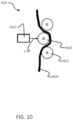
- FIG. 10 is a schematic view of another example of a second braking system 820 that can be used with the descent device 800 (shown in FIG. 9 ).
- the second braking system 820 can move relative to the line 806 so as to increase the friction in the line system and generate a braking force. For example, by adjusting the fleet angle of the line 806 through one or more friction elements 822. As such, the second braking system 820 can lower the load on the line 806 at a second descent rate in a lock-off operational configuration.
- the second braking system 820 can be a device that uses a mechanical camming mechanism (not shown) that applies mechanical friction to the line 806 to regulate the applied braking force.
- the controller 114 (shown in FIG. 1 ) of the descent device 800 is used to engage and disengage the second braking system 820 as described above.
- the second braking system 814, 820 could be a cable catch (not shown) that selectively engages with the line 806 in a lock-off operational configuration.
- the cable catch can be fixed relative to the line 806 and prevents rapid extraction of the line 806 through the system when the line is loaded (e.g., upon a fall of the climber).
- the second braking system 814, 820 could be a linear magnetic eddy current brake that applies a braking force on the line 806.
- the line 806 can include either the conductor or the magnetic element as required or desired.
- the braking force applied by the eddy current brake can be scaled so as to define the second descent rate.
- the second braking system 814, 820 can be coupled to one or more of the pulleys 808 so that the braking force can be applied through a rotational resistance on the pulley 808.
- the second braking system 814, 820 can be magnetic based, electromagnetic based, friction based, fan based, etc. as required or desired.
- the second braking system 814, 820 can also couple to the rotational shafts of the pulleys 808.
- the second braking system 814, 820 described in FIGS. 9 and 10 acts on the line 806 of the descent device 800. It should be appreciated that a braking system acting on a line of any of the descent devices (e.g., a fan braking system, a friction braking system, a hydraulic braking system, an electromagnetic braking system, and a magnetic braking system) can be used as required or desired. In other examples, the second braking system 814, 820 could be used with a first braking system that includes a counterweight, or a motor.
- the second braking system 814, 820 can be coupled to the hydraulic cylinder 812 so as to control the second descent rate in a lock-off operational configuration.
- a secondary operator could control (e.g., open/close) a hydraulic fluid valve so as to control the flow of hydraulic fluid though the cylinder 812.
- This operator can be coupled to a pressure sensor that monitors the pressure of the fluid within the hydraulic cylinder 812 to determine the position of the valve and the force of the hydraulic damper.
- the sensors and valve operator can be operably coupled to the control station 204 (shown in FIG. 2 ) as required or desired.
- the second braking system 814, 820 can be a magnetic based braking system coupled to the cylinder 812 (e.g., a linear eddy current brake system) to slow the extension of the rod within the cylinder and generate the braking force.
- a magnetic based braking system coupled to the cylinder 812 (e.g., a linear eddy current brake system) to slow the extension of the rod within the cylinder and generate the braking force.
- FIG. 11 is a schematic view of another automatic descent control device 900 for use with the automatic descent control systems described above. Similar to the device described in FIG. 9 , in this example, the descent device 900 includes a first braking system 902 that is a hydraulic braking system with a first hydraulic cylinder 904. The movement of the cylinder 904 via hydraulic fluid lowers the climber via a line 906 at a first descent rate in a normal operational configuration. Additionally, the descent device 900 includes a second braking system 908 that is a hydraulic braking system with a second hydraulic cylinder 910 in series with the first braking system 902. The movement of the cylinder 910 via hydraulic fluid lowers the climber via the line 906 at a second descent rate in a lock-off operational configuration. In this example, the climber is attached to both braking systems 902, 908 simultaneously.
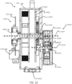
- FIG. 12 is a perspective view of another automatic descent control device 1000 for use with the automatic descent control systems described above.
- FIG. 13 is a cross-sectional view of the descent device 1000.
- the descent device 1000 includes a line system 1002 disposed at least partially within a housing 1004.
- the line system 1002 includes a drum 1006 mounted on a first rotatable shaft 1008 that is rotatably supported by the housing 1004 by one or more bearings 1010.
- the line system 1002 also includes a line (not shown) that is configured to be attached to a climber.
- the line is wound at least partially around the drum 1006 and extends through an opening 1012 at the bottom of the housing 1004.
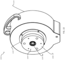
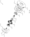
- the descent device 1300 includes a first braking system (not shown) that is an eddy current brake system, although, any other braking system described herein may be utilized, for use in a normal operational configuration.
- the components of the first braking system are coupled to and disposed around the rotatable shaft 1304 such that the rotatable shaft 1304 rotates as the user climbs and descends.
- the second braking system 1306 is disengaged so that no additional braking forces are generated on the shaft 1304.
- the controller 1307 can collect and/or transmit data during the normal operational configuration as required or desired.
- FIG. 20 is a front view of an exemplary interface hold 1400.
- FIG. 21 is a perspective cross-sectional view of the interface hold 1400 taken along line 21-21.
- the interface hold 1400 is one example of an engagement device described herein that enables the descent device to be remotely switched between the normal operational configuration and the lock-off operational configuration.
- the interface hold 1400 is configured to couple in communication with the descent devices described herein.
- the interface hold 1400 includes one or more buttons 1402 that when actuated (e.g., pressed) remotely engages the lock-off operational configuration of the descent device.
- the interface hold 1400 can take any other shape as required or desired, including shapes that correspond to known climbing holds.
- the button 1402 is disposed at the bottom of the housing cover 1406, however, other locations are contemplated herein.
- the housing cover 1406 may include a visual indicator (e.g., LED light, display screen, or the like) that enables the system to indicate the operational configuration of the descent device and/or any other status condition of the descent device (e.g., on/off, etc.).
- the controller 1414 enables communication with the descent device and for power to be supplied thereto. It should be appreciated, however, that in other examples, the descent device may have its own power source as required or desired.
- the interface hold 1400 can be water resistant for use with outdoor climbing walls.
Landscapes
- Engineering & Computer Science (AREA)
- General Engineering & Computer Science (AREA)
- Mechanical Engineering (AREA)
- Health & Medical Sciences (AREA)
- General Health & Medical Sciences (AREA)
- Business, Economics & Management (AREA)
- Emergency Management (AREA)
- Power Engineering (AREA)
- Emergency Lowering Means (AREA)
- Braking Arrangements (AREA)
- Stopping Of Electric Motors (AREA)
Claims (14)
- Automatische Abstiegskontrollvorrichtung (1000, 1300), umfassend:ein Gehäuse (1004, 1302);eine Welle (1008, 1304), die drehbar in dem Gehäuse (1004, 1302) gelagert wird;ein Seil (110), das dazu konfiguriert ist, an einer Last (108) befestigt zu werden, wobei das Seil mit der Welle (1008, 1304) gekoppelt ist, und wobei das Seil (110) sich in das Gehäuse (1004, 1302) einzieht und sich um die Welle (1008, 1304) wickelt, wenn das Seil (110) nicht belastet wird, und sich von der Welle (1008, 1304) abwickelt, wenn das Seil (110) belastet wird;ein erstes Bremssystem (1016), das mit der Welle (1008, 1304) gekoppelt ist, wobei das erste Bremssystem (1016) ein Wirbelstrombremssystem ist und eine erste Bremskraft auf die Welle (1008, 1304) ausübt, wenn das Seil (110) belastet wird, wobei das erste Bremssystem (1016) die Last (108) mit einer ersten Abstiegsgeschwindigkeit absenkt;ein zweites Bremssystem (1200, 1306), das mit der Welle (1008, 1304) gekoppelt ist, wobei das zweite Bremssystem (1200, 1306) ein elektromechanisches Bremssystem ist und eine zweite Bremskraft auf die Welle (1008, 1304) ausübt, wenn das Seil (110) belastet wird, wobei das zweite Bremssystem (1200, 1306) die Last (108) mit einer zweiten Abstiegsgeschwindigkeit absenkt oder verriegelt, und wobei die Last (108) konstant ist, und die erste Abstiegsgeschwindigkeit größer als die zweite Abstiegsgeschwindigkeit ist; undein Steuergerät (1036, 1307), das mit dem zweiten Bremssystem (1200, 1306) gekoppelt ist, wobei das Steuergerät (1036, 1307) mit dem zweiten Bremssystem (1200, 1306) selektiv bei Empfang eines Einschaltssignals eingeschaltet wird, wobei das zweite Bremssystem (1200, 1306) unabhängig von dem ersten Bremssystem (1016) ist.
- Automatische Abstiegskontrollvorrichtung nach Anspruch 1, wobei das Steuergerät (1036, 1307) bei einer vorbestimmten Zeitdauer automatisch von dem zweiten Bremssystem (1200, 1306) in das erste Bremssystem (1016) umschaltet.
- Automatische Abstiegskontrollvorrichtung nach Anspruch 1, ferner umfassend einen Sensor (118), der dazu konfiguriert ist, zu erkennen, wenn das Seil (110) belastet wird, und das Einschaltssignal an das Steuergerät (1036, 1307) zu senden.
- Automatische Abstiegskontrollvorrichtung nach Anspruch 1, ferner umfassend eine Einschalttaste (1402), die konfiguriert ist, das Einschaltssignal zu erzeugen, und wobei sich die Einschalttaste (1402) entfernt von dem Gehäuse (1004, 1302) befindet.
- Automatische Abstiegskontrollvorrichtung nach Anspruch 1, wobei die automatische Abstiegskontrollvorrichtung (1000, 1300) automatisch in dem ersten Bremssystem (1016) arbeitet, sofern das zweite Bremssystem (1200, 1306) eingeschaltet wird.
- Automatische Abstiegskontrollvorrichtung nach Anspruch 1, wobei die zweite Abstiegsgeschwindigkeit die Position des Seils (110) verriegelt und das Absenken der Last (108) verhindert.
- Automatische Abstiegskontrollvorrichtung nach Anspruch 1, wobei das elektromechanische Bremssystem (1306) umfasst:eine Kupplungswelle (1316), die konfiguriert ist, mit der Welle (1304) gekoppelt zu werden;ein Kupplungslager (1324), das mit der Kupplungswelle (1316) gekoppelt ist;eine Bremsnabe (1308), die mit dem Kupplungslager (1324) gekoppelt ist, wobei die Kupplungswelle (1316), das Kupplungslager (1324) und die Bremsnabe (1308) alle koaxial sind und durch die Welle (1304) drehbar angetrieben werden;ein Klemmrad (1312), das mit dem Gehäuse (1302) gekoppelt ist; undein Bremsbelag (1310), der mit dem Klemmrad (1312) gekoppelt ist.
- Automatische Abstiegskontrollvorrichtung nach Anspruch 7, wobei das Klemmrad (1312) eine elektrische Spule umfasst, die konfiguriert ist, ein Magnetfeld zu erzeugen.
- Automatische Abstiegskontrollvorrichtung nach Anspruch 1, wobei das elektromechanische Bremssystem (1306) umfasst:ein Reluktorrad (1328); undeinen Sensor (1334), wobei der Sensor (1334) konfiguriert ist, die Drehgeschwindigkeit und Drehrichtung der Welle (1304) über das Reluktorrad (1328) zu messen.
- Automatische Abstiegskontrollvorrichtung nach Anspruch 1, wobei das zweite Bremssystem (1306) umfasst:eine Kupplungswelle (1316), die konfiguriert ist, mit der Welle (1304) der automatischen Abstiegskontrollvorrichtung (1300) gekoppelt zu werden und durch diese in Drehung versetzt zu werden;eine Rotorbaugruppe (1322, 1324, 1326, 1328), die mit der Kupplungswelle (1316) gekoppelt ist; undeine Statorbaugruppe (1312, 1310), die in Bezug auf die Rotorbaugruppe fest ist, wobei die Rotorbaugruppe und die Statorbaugruppe konfiguriert sind, die zweite Bremskraft in Bezug auf die Welle (1304) über die Kupplungswelle (1316) zu erzeugen.
- Automatische Abstiegskontrollvorrichtung nach Anspruch 10, wobei die zweite Bremskraft reibungsbasiert ist.
- Automatische Abstiegskontrollvorrichtung nach Anspruch 10, wobei die Rotorbaugruppe umfasst:ein Kupplungslager (1324), das mit der Kupplungswelle (1316) gekoppelt ist; undeine Bremsnabe (1308), die mit dem Kupplungslager (1324) gekoppelt ist, wobei die Kupplungswelle (1316), das Kupplungslager (1324) und die Bremsnabe (1308) alle koaxial sind und durch die Welle (1304) drehbar angetrieben werden.
- Automatische Abstiegskontrollvorrichtung nach Anspruch 10, wobei die Statorbaugruppe umfasst:ein Klemmrad (1312), das mit dem Gehäuse (1302) gekoppelt ist; undeinen Bremsbelag (1310), der mit dem Klemmrad (1312) gekoppelt ist.
- Automatische Abstiegskontrollvorrichtung nach Anspruch 10, wobei das Steuergerät (1307) konfiguriert ist, die Drehgeschwindigkeit und Drehrichtung der Welle (1304) über ein Reluktorrad (1328) zu messen.
Applications Claiming Priority (3)
| Application Number | Priority Date | Filing Date | Title |
|---|---|---|---|
| US201962903385P | 2019-09-20 | 2019-09-20 | |
| US202063021423P | 2020-05-07 | 2020-05-07 | |
| PCT/US2020/051492 WO2021055748A2 (en) | 2019-09-20 | 2020-09-18 | Lock-off descent control systems and devices |
Publications (3)
| Publication Number | Publication Date |
|---|---|
| EP4031254A2 EP4031254A2 (de) | 2022-07-27 |
| EP4031254B1 true EP4031254B1 (de) | 2025-07-09 |
| EP4031254C0 EP4031254C0 (de) | 2025-07-09 |
Family
ID=73014586
Family Applications (1)
| Application Number | Title | Priority Date | Filing Date |
|---|---|---|---|
| EP20797240.7A Active EP4031254B1 (de) | 2019-09-20 | 2020-09-18 | Abschaltbare abstiegskontrollsysteme und -vorrichtungen |
Country Status (5)
| Country | Link |
|---|---|
| US (2) | US12186596B2 (de) |
| EP (1) | EP4031254B1 (de) |
| CN (1) | CN114761089B (de) |
| ES (1) | ES3042151T3 (de) |
| WO (1) | WO2021055748A2 (de) |
Families Citing this family (6)
| Publication number | Priority date | Publication date | Assignee | Title |
|---|---|---|---|---|
| US20200114182A1 (en) * | 2018-10-10 | 2020-04-16 | Everlast Climbing Industries, Inc. | Climbing wall comprising track-based support harness |
| CN112930217B (zh) * | 2019-07-24 | 2022-08-09 | 上海爱科锐特控制技术有限公司 | 一种高层楼宇智能救生系统和用于智能速降的机电装置 |
| CN115348886B (zh) | 2020-03-18 | 2024-10-15 | 特鲁布鲁有限公司 | 线分配装置 |
| IT202000006769A1 (it) * | 2020-03-31 | 2021-10-01 | Prograde S R L | Apparecchiatura di sicurezza per arrampicata sportiva. |
| US12076594B2 (en) * | 2020-11-23 | 2024-09-03 | Yoke Industrial Corp. | Fall arrester |
| US12431780B2 (en) * | 2022-06-23 | 2025-09-30 | Applied Research Associates, Inc. | Magnetic braking system for descending payloads |
Family Cites Families (207)
| Publication number | Priority date | Publication date | Assignee | Title |
|---|---|---|---|---|
| US2058024A (en) | 1934-12-11 | 1936-10-20 | Westinghouse Air Brake Co | Eddy current brake |
| US2112312A (en) | 1935-09-05 | 1938-03-29 | Moore Drop Forging Company | One-piece shrouded hinge member and method of forming same |
| US2122315A (en) | 1936-06-11 | 1938-06-28 | Fosty Leopold | Fire escape |
| BE464392A (de) | 1944-06-14 | |||
| US2409009A (en) | 1945-07-24 | 1946-10-08 | Gen Electric | One-way drive with magnetic lock |
| US2438223A (en) * | 1945-10-30 | 1948-03-23 | Lear Inc | Magnetically actuated clutch and brake construction |
| US2492776A (en) | 1948-08-11 | 1949-12-27 | Martin P Winther | Dynamoelectric machine |
| GB721748A (en) | 1950-06-22 | 1955-01-12 | Baermann Max | Improvements in or relating to permanent magnet brakes or clutches |
| US2771171A (en) | 1955-07-06 | 1956-11-20 | Lab Equipment Corp | Magnetically activated torque coupling |
| GB908128A (en) | 1958-06-10 | 1962-10-17 | Andre Duban | Improvements in or relating to ratchet-and-pawl devices |
| FR1418814A (fr) | 1964-03-27 | 1965-11-26 | Renault | Perfectionnements aux dispositifs à courants de foucault pour la commande automatique des changements de rapports de vitesses sur véhicules |
| US3447006A (en) | 1967-09-28 | 1969-05-27 | Bliss Co | Electrodynamic brake of magnetic fluid type |
| DE2032935A1 (de) | 1970-07-03 | 1972-01-13 | Kabel Metallwerke Ghh | Vorrichtung zur Konstanthaltung von Geschwindigkeit und Zugkraft eines von einer Spule ablaufenden Drahtes |
| CA988476A (en) * | 1972-05-22 | 1976-05-04 | Masao Tsuda | Slow descender |
| DE2402748C2 (de) | 1974-01-21 | 1986-07-03 | Artur 7060 Schorndorf Föhl | Vorrichtung zur Einleitung der Spulenwellenblockierung eines Sicherheitsgurt- Aufrollautomaten |
| US3962595A (en) | 1974-12-20 | 1976-06-08 | W. J. Industries, Incorporated | Magnetic particle brake |
| JPS5296287U (de) | 1976-01-19 | 1977-07-19 | ||
| US4078719A (en) | 1976-04-29 | 1978-03-14 | Beckman Instruments, Inc. | Eddy current brake for air driven centrifuge |
| US4093186A (en) | 1976-11-22 | 1978-06-06 | Golden Steven T | Line brake device useful for fire escape |
| GB1599300A (en) | 1977-08-27 | 1981-09-30 | Ferranti Ltd | Speed control |
| US4271944A (en) | 1979-02-12 | 1981-06-09 | Hanson Douglas R | Single revolution torque limiting clutch |
| US4306688A (en) | 1979-02-22 | 1981-12-22 | Injecto Mold, Inc. | Hose reel assembly |
| US4434971A (en) | 1981-02-11 | 1984-03-06 | Armco Inc. | Drilling rig drawworks hook load overspeed preventing system |
| US4561605A (en) | 1981-12-25 | 1985-12-31 | Shimano Industrial Company Limited | Brake for a fishing reel |
| US4416430A (en) | 1982-02-01 | 1983-11-22 | Draft Systems, Inc. | Load lowering device |
| US4544111A (en) | 1982-03-09 | 1985-10-01 | Shimano Industrial Company Limited | Brake for a fishing reel |
| JPS59217589A (ja) | 1983-05-26 | 1984-12-07 | 株式会社宮野鉄工所 | 緩降機 |
| US4511123A (en) | 1983-06-02 | 1985-04-16 | Meyer Ostrobrod | Safety device |
| US4612469A (en) | 1983-11-10 | 1986-09-16 | Kabushiki Kaisha Sankyo Seiki Seisakusho | Speed governor |
| JPS6115557A (ja) | 1984-06-30 | 1986-01-23 | Toshiba Corp | 浮上式搬送装置 |
| US4601438A (en) | 1985-04-29 | 1986-07-22 | Charles C. Worth Corporation | Bait casting reel with braking device |
| US4957644A (en) | 1986-05-13 | 1990-09-18 | Price John T | Magnetically controllable couplings containing ferrofluids |
| DE3864969D1 (de) | 1987-04-30 | 1991-10-24 | Tokyo Buhin Kogyo Co Ltd | Foucaultstrombremse. |
| FR2631089B1 (fr) * | 1988-05-06 | 1991-02-08 | Valeo | Dispositif d'embrayage muni de moyens de mesure de vitesse d'arbres |
| US4877110A (en) | 1988-10-14 | 1989-10-31 | D B Industries, Inc. | Safety device with retractable lifeline |
| CA1315328C (en) | 1988-10-31 | 1993-03-30 | Kenji Araki | Eddy current retarder |
| US4938435A (en) | 1988-12-30 | 1990-07-03 | Frost Engineering Development Corporation | Personnel lowering device |
| KR910021550A (ko) | 1990-02-02 | 1991-12-20 | 발터 쾰러 | 와이어 브레이크 |
| DE4018214A1 (de) | 1990-06-07 | 1991-12-12 | Harting Elektronik Gmbh | Vorrichtung zur elektromagnetischen betaetigung eines sperrmechanismus eines gurtaufrollers |
| GB9027783D0 (en) | 1990-12-21 | 1991-02-13 | Barrow Hepburn Sala Ltd | Safety anchorages for controlling pay-out of a safety line |
| US5205386A (en) | 1992-03-05 | 1993-04-27 | United Technologies Corporation | Pawl and ratchet clutch with pawl holdback |
| JPH0572612U (ja) | 1992-03-09 | 1993-10-05 | 株式会社東海理化電機製作所 | ウエビング巻取装置 |
| JP3584473B2 (ja) | 1992-04-22 | 2004-11-04 | Fdk株式会社 | 磁気ダンパ装置 |
| DE9300966U1 (de) | 1993-01-25 | 1993-03-11 | Chen, Jeff, Shyong City | Drehmomentkontrollvorrichtung |
| US5712520A (en) | 1993-05-21 | 1998-01-27 | Magna Force, Inc. | Permanent magnet braking system |
| US5691587A (en) | 1993-05-21 | 1997-11-25 | Magna Force, Inc. | Magnetic centrifugal clutch |
| US5636804A (en) | 1993-10-05 | 1997-06-10 | Bando Leports, Ltd. | Double-bearing fishing reel |
| WO1995016496A1 (en) | 1993-12-14 | 1995-06-22 | Strickler James H | Sport climbing safety device |
| EP0662569A1 (de) | 1994-01-10 | 1995-07-12 | Iwao Ikegami | Bremse |
| JPH09507418A (ja) | 1994-01-13 | 1997-07-29 | バロー・ヘップバーン・サラ・リミテッド | 主に落下防止装置に用いられる速度応答型係止デバイス |
| EP0740570B1 (de) | 1994-01-18 | 1997-12-03 | Barrow Hepburn Sala Limited | Kupplungsmechanismus zum gebrauch in sicherheitsapparat |
| JP2929517B2 (ja) | 1994-04-01 | 1999-08-03 | ダイワ精工株式会社 | 魚釣用リールのバックラッシュ防止装置 |
| US5441137A (en) | 1994-05-04 | 1995-08-15 | Eaton Corporation | Clutch with a centrifugally applied ball ramp actuator |
| US5862891A (en) | 1994-10-28 | 1999-01-26 | Knorr-Bremse Systeme Fur Scheinenfahrzeuge Gmbh | Electromagnetic or permanent-magnetic rail brake |
| US5862903A (en) | 1994-12-02 | 1999-01-26 | Itt Automotive Electrical Systems, Inc. | Centrifugal clutch for power door locks |
| DE29506374U1 (de) | 1995-04-13 | 1996-10-02 | FUNEX AG, Wollerau | Belustigungsvorrichtung |
| US5791584A (en) | 1996-01-25 | 1998-08-11 | Kuroiwa; Sachimasa | Tension control unit for filamentous material |
| US5822874A (en) | 1996-04-29 | 1998-10-20 | Nemes; Anne | Automatically retracting chalk line marking tool |
| DE19618903C2 (de) | 1996-05-10 | 1998-03-19 | Knorr Bremse Systeme | Magnetische Bremse, insbesondere lineare Wirbelstrombremse |
| US20040194101A1 (en) | 1997-08-21 | 2004-09-30 | Glanzer David A. | Flexible function blocks |
| JPH1098868A (ja) | 1996-09-24 | 1998-04-14 | Aichi Steel Works Ltd | 電磁ブレーキの磁極配列方式 |
| US5779178A (en) | 1996-11-07 | 1998-07-14 | Rostra Precision Controls, Inc. | Seat belt retractor assembly having magnetically actuated locking mechanism |
| JPH10140536A (ja) | 1996-11-12 | 1998-05-26 | Taisei Corp | 水中マット布設用架台と水中マット布設方法 |
| US5711404A (en) | 1997-02-05 | 1998-01-27 | Lee; Ying-Che | Magnetic adjustable loading device with eddy current |
| US5742986A (en) | 1997-02-13 | 1998-04-28 | Trw Inc. | Seat belt buckle with hall effect locking indicator and method of use |
| US6086005A (en) | 1997-03-11 | 2000-07-11 | Daiwa Seiko, Inc. | Fishing reel with magnetic force spool rotational-speed control during spool free rotational state |
| JPH10252025A (ja) | 1997-03-12 | 1998-09-22 | N D K:Kk | 自発光式道路鋲 |
| EP0976191A1 (de) | 1997-04-14 | 2000-02-02 | David A. Zornes | Magnetkupplung mit verbessertem elektromagnetischem drehmoment |
| JPH11119680A (ja) | 1997-10-20 | 1999-04-30 | Ricoh Co Ltd | 液晶表示装置 |
| JP3835014B2 (ja) | 1997-10-20 | 2006-10-18 | 東亞合成株式会社 | 硬化性組成物 |
| US5928300A (en) | 1997-10-30 | 1999-07-27 | Simula Inc. | Three-axis aircraft crash sensing system |
| JPH11313117A (ja) | 1998-02-27 | 1999-11-09 | Kokusai Electric Co Ltd | 周波数制御方法及び直交検波回路及びfsk受信機 |
| JP3961668B2 (ja) | 1998-05-06 | 2007-08-22 | 美和ロック株式会社 | 引戸のクローザ |
| US6042517A (en) | 1998-09-10 | 2000-03-28 | Bell Sports, Inc. | Bicycle trainer magnetic resistance device |
| DE19859445C2 (de) | 1998-12-22 | 2001-01-11 | Asm Automation Sensorik Messte | Meßseil-Wegsensor mit einem Längsantrieb für die Seiltrommel |
| DE19951221A1 (de) | 1999-04-01 | 2000-10-05 | Mannesmann Ag | Windwerk, insbesondere Hebezeug, mit einem Gehäuse |
| JP2000316272A (ja) | 1999-04-27 | 2000-11-14 | Topre Corp | 自転車の最高速度制限装置 |
| US6051897A (en) | 1999-05-05 | 2000-04-18 | Synchro-Start Products, Inc. | Solenoid actuator with positional feedback |
| JP2001017041A (ja) | 1999-07-02 | 2001-01-23 | Akebono Brake Ind Co Ltd | 両軸リール用ブレーキ機構 |
| GB2352645B (en) | 1999-07-21 | 2004-01-14 | Yu-Peng Chen | Magnetic damping device for an exercising device |
| DE29912725U1 (de) | 1999-07-21 | 1999-10-07 | Chen, Yu-Peng, Taichung | Magnetische Dämpfungseinrichtung für ein Übungsgerät |
| GB2352784A (en) | 1999-08-04 | 2001-02-07 | Moog Inc | Energy-absorbing brake |
| US6360855B1 (en) | 1999-11-15 | 2002-03-26 | Cheng Szu-Yin | Wheel for a stationary bicycle |
| US20040055836A1 (en) | 1999-11-22 | 2004-03-25 | Pribonic Edward M. | Eddy current braking apparatus with adjustable braking force |
| US6293376B1 (en) | 1999-11-22 | 2001-09-25 | Magnetar Technologies Ltd | Apparatus including eddy current braking system |
| US20060278478A1 (en) | 1999-11-22 | 2006-12-14 | Pribonic Edward M | Eddy current braking apparatus with adjustable braking force |
| GB2357563B (en) | 1999-12-21 | 2002-04-03 | Latchways Plc | Energy absorber |
| US6533083B1 (en) | 2000-02-15 | 2003-03-18 | Magnetar Technologies, Inc | Eddy current braking apparatus |
| EP1268233B1 (de) | 2000-02-15 | 2008-07-16 | Magnetar Technologies Ltd. | Wirbelstrombremsvorrichtung |
| DE20003513U1 (de) | 2000-02-28 | 2001-07-26 | Wirth Maschinen- und Bohrgeräte-Fabrik GmbH, 41812 Erkelenz | Hebewerk |
| DE60133201T2 (de) | 2000-07-06 | 2009-04-30 | Mine Safety Appliances Co. | Gerät zum kontrollierten herablassen |
| US6412611B1 (en) | 2000-07-17 | 2002-07-02 | Magnetar Technologies, Ltd | Eddy current brake system with dual use conductor fin |
| DE60141315D1 (de) | 2000-09-18 | 2010-04-01 | Isuzu Motors Ltd | Wirbelstrombremse mit einem Magnet bestehend aus einem Elektromagnet und einem Dauermagnet |
| WO2002027206A1 (fr) | 2000-09-29 | 2002-04-04 | Feng Jin | Roue libre |
| US20020162477A1 (en) | 2001-03-02 | 2002-11-07 | Emiliano Palumbo | Dual cable zipline having mechanical ascension and braking systems |
| US7014026B2 (en) | 2001-06-07 | 2006-03-21 | Drussel Wilfley Design, L.L.C. | Manual/automatic pressure control mechanism for centrifugal clutch |
| DE10149112B4 (de) | 2001-10-05 | 2004-11-25 | Robert Bosch Gmbh | Verfahren zur Bestimmung einer Auslöseentscheidung für Rückhaltemittel in einem Fahrzeug |
| US6585087B2 (en) | 2001-10-12 | 2003-07-01 | Yuan Ho Chuen Co., Ltd. | Control mechanism for use in magnetically operated wheels |
| US6557673B1 (en) | 2001-12-21 | 2003-05-06 | Visteon Global Technologies, Inc. | Integral park brake/eddy current brake assembly |
| US6698554B2 (en) | 2001-12-21 | 2004-03-02 | Visteon Global Technologies, Inc. | Eddy current brake system |
| AU2002347122A1 (en) | 2001-12-28 | 2003-07-15 | Suter Racing International Ag | Abseiling device used as rescue equipment in disaster situations, particularly fires in buildings or tall buildings |
| US7011607B2 (en) | 2002-01-23 | 2006-03-14 | Saris Cycling Group, Inc. | Variable magnetic resistance unit for an exercise device |
| KR100675609B1 (ko) | 2002-02-28 | 2007-01-30 | 수미도모 메탈 인더스트리즈, 리미티드 | 와전류 감속 장치 |
| US6723017B2 (en) | 2002-05-09 | 2004-04-20 | Visteon Global Technologies, Inc. | Differential assembly |
| EP1401087A1 (de) | 2002-09-20 | 2004-03-24 | Tai-Her Yang | Axial beweglicher Rotor |
| EP1432101B1 (de) | 2002-12-20 | 2019-03-20 | Tai-Her Yang | Elektrische Maschine mit einer Struktur, um den Rotor mit Hilfe der Fliehkraft in axialer Richtung zu bewegen |
| TWI298621B (en) | 2003-01-06 | 2008-07-11 | Shimano Kk | Braking device for a dual bearing reel |
| GB2398054B (en) | 2003-01-24 | 2005-08-03 | Ropepower Ltd | Powered rope climbing apparatus |
| EP1628712A4 (de) | 2003-02-21 | 2010-05-05 | Life Pack Technologies Inc | Vorrichtung zur evakuierung von gebäuden von aussen |
| JP4067995B2 (ja) | 2003-03-28 | 2008-03-26 | ヒタチグローバルストレージテクノロジーズネザーランドビーブイ | 回転円板型記憶装置並びにアクチュエータ・サスペンション・アセンブリの解放方法 |
| TWM251925U (en) | 2003-08-21 | 2004-12-01 | Jung-Rung Shie | Brake structure for rolling door |
| US7281620B2 (en) | 2003-09-05 | 2007-10-16 | D B Industries, Inc. | Self-retracting lifeline |
| US7706777B2 (en) | 2003-09-23 | 2010-04-27 | Broadcom Corporation | Secure user interface in a shared resource environment |
| DE102004007434A1 (de) | 2004-02-16 | 2005-09-22 | Minebea Co., Ltd. | Elektrische Maschine |
| US7294947B2 (en) | 2004-03-01 | 2007-11-13 | Flux Drive, Inc. | Apparatus for transferring torque magnetically |
| WO2005090037A1 (en) | 2004-03-12 | 2005-09-29 | Intellipack | Hand held dispenser |
| DE102004013836A1 (de) | 2004-03-16 | 2005-10-06 | Bielomatik Leuze Gmbh + Co.Kg | Verfahren zum Rotationsreibschweißen von Kunststoffteilen sowie Vorrichtung zur Durchführung des Verfahrens |
| ATE374726T1 (de) | 2004-04-29 | 2007-10-15 | Terex Demag Gmbh & Co Kg | Seilaufwickelsystem zum auf- und abwickeln von kranstahlseilen |
| GB0410957D0 (en) * | 2004-05-15 | 2004-06-16 | Renton Julian E | Personal height rescue apparatus |
| US8727078B2 (en) | 2004-05-28 | 2014-05-20 | Velocity Magnetics, Inc. | Selectively incrementally actuated linear eddy current braking system |
| GB2415818B (en) | 2004-06-30 | 2008-12-31 | Autoliv Dev | Arrangement for triggering a vehicle safety device |
| US20100211239A1 (en) | 2004-08-06 | 2010-08-19 | Christensen Ladd E | Towrope Winch Dead Start |
| CN1783674A (zh) | 2004-11-24 | 2006-06-07 | 乐金电子(天津)电器有限公司 | 圆筒型涡电流轴连接装置 |
| US7018324B1 (en) | 2004-11-30 | 2006-03-28 | Lily Lin | Magnetic controlled loading device in combination of a power generating set and an adjusting drive mechanism |
| DE102005036570A1 (de) | 2004-12-16 | 2006-07-06 | Steinert Elektromagnetbau Gmbh | Verfahren zur Abbremsung eines laufenden Metallbandes und Anlage zur Durchführung des Verfahrens |
| JP5296287B2 (ja) | 2005-03-15 | 2013-09-25 | 富士電機株式会社 | 半導体装置 |
| GB0507806D0 (en) | 2005-04-19 | 2005-05-25 | Bm Engineering Uk Ltd | Belay device |
| US8079569B2 (en) | 2005-04-29 | 2011-12-20 | Gerald Lesko | Cable drawworks for a drilling rig |
| WO2006124979A2 (en) | 2005-05-18 | 2006-11-23 | Spidescape Partners Llc | Descent device |
| WO2007005560A2 (en) | 2005-06-30 | 2007-01-11 | Magnetar Technologies Corp. | Axial rotary eddy current brake with adjustable braking force |
| DE102005032694A1 (de) | 2005-07-13 | 2007-01-18 | Forhouse Corp., Shenkang | Lastregler einer Magnetbremse für ein Übungsgerät |
| GB2432140A (en) | 2005-11-15 | 2007-05-16 | Latchways Plc | Fall arrest safety device |
| US20070135561A1 (en) | 2005-12-08 | 2007-06-14 | Christian Rath | Method of dust abatement |
| US7870934B2 (en) | 2006-03-14 | 2011-01-18 | Mine Safety Appliances Company | Self-retracting lanyard and braking mechanism with pawl lockout |
| JP2007276540A (ja) | 2006-04-03 | 2007-10-25 | Honda Motor Co Ltd | 車両の乗員拘束装置 |
| US7528514B2 (en) | 2006-06-22 | 2009-05-05 | International Business Machines Corporation | Centrifugal magnetic clutch |
| WO2008008225A2 (en) | 2006-07-10 | 2008-01-17 | Sigma Industries, Llc | Retractable lifeline safety device |
| US20080074223A1 (en) | 2006-09-22 | 2008-03-27 | Pribonic Edward M | Reinforcing of permanent magnet arrays |
| US7984796B2 (en) | 2006-10-13 | 2011-07-26 | Magnetar Technologies Corp. | Motion retarding system and method |
| US7843349B2 (en) | 2006-11-03 | 2010-11-30 | D B Industries, Inc. | Retrofittable radio frequency identification connector |
| US20080105503A1 (en) | 2006-11-08 | 2008-05-08 | Pribonic Edward M | Axial rotary eddy current brake with self-adjustable braking force |
| WO2008097508A1 (en) | 2007-02-02 | 2008-08-14 | Nicros, Inc. | Automatic belay warning system |
| GB2451799B (en) | 2007-05-16 | 2011-12-14 | Latchways Plc | Safety device |
| TWI339588B (en) | 2007-06-25 | 2011-04-01 | Lifeline Descent Systems Pty Ltd | Descent device |
| WO2009011921A1 (en) | 2007-07-18 | 2009-01-22 | Stone Kevin R | Personal escape device and methods for using same |
| GB2449134B (en) | 2007-08-13 | 2009-08-12 | Checkmate Safety Llp | Fall arrest block |
| US7780146B2 (en) | 2007-09-28 | 2010-08-24 | D B Industries, Inc. | Retrieval assembly |
| US10322306B2 (en) | 2007-10-12 | 2019-06-18 | Latchways Plc | Rotational energy absorber and fall arrest system |
| CA2646073C (en) | 2007-12-10 | 2011-02-01 | Rapid Egress Descent Systems Ltd. | Descent control device |
| US9016432B2 (en) | 2007-12-10 | 2015-04-28 | Rapid Egress Descent Systems Ltd. | Descent control device |
| US7918323B2 (en) | 2007-12-16 | 2011-04-05 | Sports Art Industrial Co., Ltd | Magnetic resistor control assembly |
| JP5122273B2 (ja) | 2007-12-28 | 2013-01-16 | 株式会社シマノ | 両軸受リールのスプール制動装置 |
| WO2009108040A1 (en) | 2008-02-27 | 2009-09-03 | Rapid Vertical Egress System Holding B.V. | Rescue arrangement |
| US8141681B2 (en) * | 2008-04-07 | 2012-03-27 | Safeworks, Llc | Tower climbing assist device |
| CN101559267A (zh) | 2008-04-18 | 2009-10-21 | 陈锦鹏 | 一种防坠落设备及系统 |
| US10001804B2 (en) | 2008-08-11 | 2018-06-19 | Force Dimension S.A.R.L. | Force-feedback device and method |
| US20100112224A1 (en) | 2008-10-30 | 2010-05-06 | James A Lott | Methods and formulations for protection ans dust control involving bulk material |
| US20100116922A1 (en) | 2008-11-13 | 2010-05-13 | Reliance Industries, Llc | Cable reel lock for fall arrestor |
| US10688323B2 (en) | 2009-03-09 | 2020-06-23 | D B Industries, Llc | Safety device with fall arrest and descending modes |
| US9764172B2 (en) * | 2009-03-09 | 2017-09-19 | D B Industries, Llc | Safety device with fall arrest and descending modes |
| NZ575464A (en) | 2009-03-10 | 2010-07-30 | Holmes Solutions Ltd | Improvements in and relating to braking mechanisms |
| KR100969227B1 (ko) | 2009-09-28 | 2010-07-14 | 주식회사 코커스 | 낚시용 릴의 브레이크 시스템 |
| DE112009005302B4 (de) | 2009-10-09 | 2021-03-11 | Toyota Jidosha Kabushiki Kaisha | Rotierende elektrische Maschinenvorrichtung |
| US8251176B2 (en) | 2009-10-14 | 2012-08-28 | D B Industries, Inc. | Self-retracting lifeline with disconnectable lifeline |
| US8556234B2 (en) | 2009-11-13 | 2013-10-15 | Ride Inc. | Single cable descent control device |
| EP2516020B1 (de) | 2009-12-23 | 2015-05-27 | D B Industries, LLC | Sturzsicherungsvorrichtung mit bremsmechanismus |
| US20110174914A1 (en) | 2010-01-20 | 2011-07-21 | Gimmal Co., Ltd. | Connector device to prevent person from falling |
| DE102010000363A1 (de) * | 2010-02-11 | 2011-08-11 | Widmesser, Florian, Dipl.-Ing., 93053 | Sicherungsvorrichtung, insbesondere Seilsicherung |
| GB201002854D0 (en) | 2010-02-19 | 2010-04-07 | Wavefront Reservoir Technologies Ltd | Magnet - operated pulsing tool |
| US20110240403A1 (en) | 2010-03-31 | 2011-10-06 | D B Industries, Inc. | Lifeline Connector for Use with Self-Retracting Lifeline with Disconnectable Lifeline |
| EP2377783A1 (de) | 2010-04-14 | 2011-10-19 | Interroll Holding AG | Förderrolle mit Fliehkraftbetätigter Magnetbremse. |
| US9199103B2 (en) | 2010-05-12 | 2015-12-01 | Msa Technology, Llc | Fall protection arrangement |
| US8469149B2 (en) | 2010-06-07 | 2013-06-25 | D B Industries, Llc | Self-retracting lifeline with disconnectable lifeline |
| DE102010032516A1 (de) * | 2010-07-28 | 2012-02-02 | Knorr-Bremse Systeme für Schienenfahrzeuge GmbH | Bremsvorrichtung mit einem die Bremsscheibe einer Reibungsscheibenbremse bildenden Rotor einer Wirbelstromscheibenbremse |
| WO2012068420A2 (en) | 2010-11-17 | 2012-05-24 | Reliance Industries, Llc | Retractable fall arrester with component assembly and cantilevered main shaft |
| US8424460B2 (en) | 2010-12-28 | 2013-04-23 | Shawn Geoffrey LERNER | Trolley for downhill zip line thrill ride |
| WO2013003402A2 (en) | 2011-06-29 | 2013-01-03 | Key Safety Systems, Inc. | Fall arrester |
| CN202203305U (zh) | 2011-08-01 | 2012-04-25 | 台州市黄岩华阳机电科技有限公司 | 离心式离合器和具有该离合器的电动车变挡驱动轮毂 |
| JP5781619B2 (ja) | 2011-09-27 | 2015-09-24 | ナブテスコ株式会社 | 車両の速度抑制装置及び速度抑制装置を備えた車両 |
| US9121462B2 (en) | 2011-10-28 | 2015-09-01 | D B Industries, Llc | Self-retracting lifeline |
| US9033115B2 (en) | 2011-11-11 | 2015-05-19 | Shawn Lerner | Zip line braking |
| US8601951B2 (en) | 2011-11-11 | 2013-12-10 | Shawn Lerner | Self-cooling trolley |
| CN102497085A (zh) | 2011-12-23 | 2012-06-13 | 浙江大学 | 一种基于Halbach阵列的永磁涡流缓速器 |
| US8857578B2 (en) | 2012-01-19 | 2014-10-14 | Technical Film Systems, Inc. | Magnetic brake |
| DE102012202553A1 (de) | 2012-02-20 | 2013-08-22 | Carl Zeiss Smt Gmbh | Lithographievorrichtung mit dämpfungsvorrichtung |
| CN102627063B (zh) | 2012-03-05 | 2014-05-28 | 江苏大学 | 电磁馈能型半主动悬架运动方向实时控制装置及方法 |
| US20140110947A1 (en) | 2012-10-24 | 2014-04-24 | Vestas Wind Systems A/S | Wind turbine generator having an eddy current brake, wind turbine having such a generator, and associated methods |
| US10004927B2 (en) | 2012-12-02 | 2018-06-26 | Reliance Industries, Llc | Retractable lanyard lock mechanism |
| CN103127627B (zh) | 2013-01-30 | 2015-07-08 | 黄柏源 | 一种双制动往返可控式缓降器 |
| CN103244577A (zh) | 2013-04-27 | 2013-08-14 | 上海法诺格绿色能源系统有限公司 | 超越离合器 |
| CN103326538B (zh) | 2013-06-25 | 2016-01-20 | 常州市博能节能科技有限公司 | 永磁智能调速节能装置 |
| NZ619034A (en) | 2013-12-16 | 2015-03-27 | Eddy Current Ltd Partnership | An assembly to control relative speed of movement between parts |
| US10046745B2 (en) | 2014-03-20 | 2018-08-14 | TruBlue LLC | Cable-traversing trolley adapted for use with impact braking |
| TWM492758U (zh) | 2014-07-24 | 2015-01-01 | Chiu-Hsiang Lo | 運動器之磁控阻力調整機構 |
| KR102449222B1 (ko) | 2014-08-18 | 2022-09-28 | 에디 커런트 리미티드 파트너쉽 | 부재들 사이의 운동학적 관계의 조정 |
| CN110838781B (zh) | 2014-08-18 | 2021-12-21 | 涡流有限合伙公司 | 闩锁设备 |
| KR102284956B1 (ko) | 2014-08-18 | 2021-08-03 | 에디 커런트 리미티드 파트너쉽 | 부재들 사이의 운동학적 관계의 조정 |
| US10556138B2 (en) * | 2014-10-02 | 2020-02-11 | Honeywell International Inc. | Sealed self-retracting lifeline |
| KR102405797B1 (ko) | 2014-12-04 | 2022-06-03 | 에디 커런트 리미티드 파트너쉽 | 요소들 사이에서의 래치 활성화 |
| DE102015109444B4 (de) | 2015-06-12 | 2018-08-02 | Bornack Gmbh & Co. Kg | Seilsicherungsvorrichtung |
| US10022570B2 (en) | 2016-05-20 | 2018-07-17 | Bailout, LLC | Personal escape device with eddy current braking |
| US9723823B2 (en) | 2016-08-29 | 2017-08-08 | Terry Richardson | Fishing line dispenser |
| GB2556892B (en) | 2016-11-23 | 2022-04-27 | Latchways Plc | Self-retracting lifeline fall arrest device |
| US20190015687A1 (en) * | 2017-07-17 | 2019-01-17 | Safeworks, Llc | Climb assist and fall arrest system |
| US10333378B2 (en) | 2017-10-06 | 2019-06-25 | Zip-Flyer, Llc | Speed restriction system using eddy currents |
| CN209253971U (zh) * | 2018-11-27 | 2019-08-16 | 陈伟晓 | 一种多功能高空作业升降器 |
| CN115348886B (zh) | 2020-03-18 | 2024-10-15 | 特鲁布鲁有限公司 | 线分配装置 |
-
2020
- 2020-09-18 EP EP20797240.7A patent/EP4031254B1/de active Active
- 2020-09-18 CN CN202080080391.6A patent/CN114761089B/zh active Active
- 2020-09-18 ES ES20797240T patent/ES3042151T3/es active Active
- 2020-09-18 WO PCT/US2020/051492 patent/WO2021055748A2/en not_active Ceased
- 2020-09-18 US US17/025,040 patent/US12186596B2/en active Active
-
2024
- 2024-11-12 US US18/944,218 patent/US20250170430A1/en active Pending
Also Published As
| Publication number | Publication date |
|---|---|
| WO2021055748A3 (en) | 2021-04-29 |
| WO2021055748A2 (en) | 2021-03-25 |
| CN114761089B (zh) | 2024-03-15 |
| US20250170430A1 (en) | 2025-05-29 |
| US12186596B2 (en) | 2025-01-07 |
| CN114761089A (zh) | 2022-07-15 |
| US20210086002A1 (en) | 2021-03-25 |
| EP4031254C0 (de) | 2025-07-09 |
| EP4031254A2 (de) | 2022-07-27 |
| ES3042151T3 (en) | 2025-11-18 |
Similar Documents
| Publication | Publication Date | Title |
|---|---|---|
| US12186596B2 (en) | Lock-off descent control systems and devices | |
| AU2017342350B2 (en) | Methods and apparatus for generating energy using fall protection devices | |
| RU2396998C2 (ru) | Страховочное устройство | |
| US9016435B2 (en) | Line dispensing device with eddy current braking for use with climbing and evacuation | |
| EP0516798B1 (de) | Sicherheitsverankerung zum reglen der sicherungsseilausgabe | |
| US20190015687A1 (en) | Climb assist and fall arrest system | |
| EP2777771A2 (de) | Sturzschutzvorrichtung mit einem Bremsmechanismus | |
| WO2009106018A1 (en) | Escape devices for high-rise buildings | |
| EP4121176B1 (de) | Leitungsverteilvorrichtungen | |
| JP2005511214A (ja) | 可変速救命装置 | |
| CN120936411A (zh) | 用于跟踪救生索放出和缩回的系统和方法 | |
| US7226038B1 (en) | Load arrestor, lifting system and method | |
| WO2010151907A1 (en) | Rescue equipment for high-rise building | |
| WO2008141553A1 (fr) | Appareil flottant pour gratte-ciel | |
| US20050092557A1 (en) | Abseiling device | |
| US8132650B2 (en) | System for safe descent of people or cargoes | |
| CN2870898Y (zh) | 自救降落器 | |
| CN221309345U (zh) | 一种高空逃生缓降设备 | |
| CN222479287U (zh) | 集成离心制动功能的减速机、线性驱动装置和升降设备 | |
| US20240285981A1 (en) | Controlled descent safety systems and methods | |
| CN114184228A (zh) | 一种可控距离发射式救灾用的探测器 | |
| RU29924U1 (ru) | Устройство для ограничения грузоподъёмности лебёдки | |
| CN113975666A (zh) | 逃生装置 | |
| CN115285358A (zh) | 一种无人直升机挂载平衡装置 |
Legal Events
| Date | Code | Title | Description |
|---|---|---|---|
| STAA | Information on the status of an ep patent application or granted ep patent |
Free format text: STATUS: UNKNOWN |
|
| STAA | Information on the status of an ep patent application or granted ep patent |
Free format text: STATUS: THE INTERNATIONAL PUBLICATION HAS BEEN MADE |
|
| PUAI | Public reference made under article 153(3) epc to a published international application that has entered the european phase |
Free format text: ORIGINAL CODE: 0009012 |
|
| STAA | Information on the status of an ep patent application or granted ep patent |
Free format text: STATUS: REQUEST FOR EXAMINATION WAS MADE |
|
| 17P | Request for examination filed |
Effective date: 20220315 |
|
| AK | Designated contracting states |
Kind code of ref document: A2 Designated state(s): AL AT BE BG CH CY CZ DE DK EE ES FI FR GB GR HR HU IE IS IT LI LT LU LV MC MK MT NL NO PL PT RO RS SE SI SK SM TR |
|
| DAV | Request for validation of the european patent (deleted) | ||
| DAX | Request for extension of the european patent (deleted) | ||
| STAA | Information on the status of an ep patent application or granted ep patent |
Free format text: STATUS: EXAMINATION IS IN PROGRESS |
|
| 17Q | First examination report despatched |
Effective date: 20231222 |
|
| GRAP | Despatch of communication of intention to grant a patent |
Free format text: ORIGINAL CODE: EPIDOSNIGR1 |
|
| STAA | Information on the status of an ep patent application or granted ep patent |
Free format text: STATUS: GRANT OF PATENT IS INTENDED |
|
| INTG | Intention to grant announced |
Effective date: 20250207 |
|
| GRAS | Grant fee paid |
Free format text: ORIGINAL CODE: EPIDOSNIGR3 |
|
| GRAA | (expected) grant |
Free format text: ORIGINAL CODE: 0009210 |
|
| STAA | Information on the status of an ep patent application or granted ep patent |
Free format text: STATUS: THE PATENT HAS BEEN GRANTED |
|
| AK | Designated contracting states |
Kind code of ref document: B1 Designated state(s): AL AT BE BG CH CY CZ DE DK EE ES FI FR GB GR HR HU IE IS IT LI LT LU LV MC MK MT NL NO PL PT RO RS SE SI SK SM TR |
|
| REG | Reference to a national code |
Ref country code: GB Ref legal event code: FG4D |
|
| REG | Reference to a national code |
Ref country code: CH Ref legal event code: EP |
|
| REG | Reference to a national code |
Ref country code: IE Ref legal event code: FG4D |
|
| REG | Reference to a national code |
Ref country code: DE Ref legal event code: R096 Ref document number: 602020054266 Country of ref document: DE |
|
| U01 | Request for unitary effect filed |
Effective date: 20250807 |
|
| U07 | Unitary effect registered |
Designated state(s): AT BE BG DE DK EE FI FR IT LT LU LV MT NL PT RO SE SI Effective date: 20250820 |
|
| U20 | Renewal fee for the european patent with unitary effect paid |
Year of fee payment: 6 Effective date: 20250923 |
|
| REG | Reference to a national code |
Ref country code: ES Ref legal event code: FG2A Ref document number: 3042151 Country of ref document: ES Kind code of ref document: T3 Effective date: 20251118 |
|
| PG25 | Lapsed in a contracting state [announced via postgrant information from national office to epo] |
Ref country code: IS Free format text: LAPSE BECAUSE OF FAILURE TO SUBMIT A TRANSLATION OF THE DESCRIPTION OR TO PAY THE FEE WITHIN THE PRESCRIBED TIME-LIMIT Effective date: 20251109 |
|
| PGFP | Annual fee paid to national office [announced via postgrant information from national office to epo] |
Ref country code: GB Payment date: 20251030 Year of fee payment: 6 |
|
| PG25 | Lapsed in a contracting state [announced via postgrant information from national office to epo] |
Ref country code: NO Free format text: LAPSE BECAUSE OF FAILURE TO SUBMIT A TRANSLATION OF THE DESCRIPTION OR TO PAY THE FEE WITHIN THE PRESCRIBED TIME-LIMIT Effective date: 20251009 |
|
| PG25 | Lapsed in a contracting state [announced via postgrant information from national office to epo] |
Ref country code: HR Free format text: LAPSE BECAUSE OF FAILURE TO SUBMIT A TRANSLATION OF THE DESCRIPTION OR TO PAY THE FEE WITHIN THE PRESCRIBED TIME-LIMIT Effective date: 20250709 |
|
| PG25 | Lapsed in a contracting state [announced via postgrant information from national office to epo] |
Ref country code: GR Free format text: LAPSE BECAUSE OF FAILURE TO SUBMIT A TRANSLATION OF THE DESCRIPTION OR TO PAY THE FEE WITHIN THE PRESCRIBED TIME-LIMIT Effective date: 20251010 |
|
| PG25 | Lapsed in a contracting state [announced via postgrant information from national office to epo] |
Ref country code: PL Free format text: LAPSE BECAUSE OF FAILURE TO SUBMIT A TRANSLATION OF THE DESCRIPTION OR TO PAY THE FEE WITHIN THE PRESCRIBED TIME-LIMIT Effective date: 20250709 |
|
| PG25 | Lapsed in a contracting state [announced via postgrant information from national office to epo] |
Ref country code: RS Free format text: LAPSE BECAUSE OF FAILURE TO SUBMIT A TRANSLATION OF THE DESCRIPTION OR TO PAY THE FEE WITHIN THE PRESCRIBED TIME-LIMIT Effective date: 20251009 |
|
| PGFP | Annual fee paid to national office [announced via postgrant information from national office to epo] |
Ref country code: ES Payment date: 20251001 Year of fee payment: 6 |
|
| PG25 | Lapsed in a contracting state [announced via postgrant information from national office to epo] |
Ref country code: SM Free format text: LAPSE BECAUSE OF FAILURE TO SUBMIT A TRANSLATION OF THE DESCRIPTION OR TO PAY THE FEE WITHIN THE PRESCRIBED TIME-LIMIT Effective date: 20250709 |
|
| PG25 | Lapsed in a contracting state [announced via postgrant information from national office to epo] |
Ref country code: CZ Free format text: LAPSE BECAUSE OF FAILURE TO SUBMIT A TRANSLATION OF THE DESCRIPTION OR TO PAY THE FEE WITHIN THE PRESCRIBED TIME-LIMIT Effective date: 20250709 |
|
| REG | Reference to a national code |
Ref country code: CH Ref legal event code: H13 Free format text: ST27 STATUS EVENT CODE: U-0-0-H10-H13 (AS PROVIDED BY THE NATIONAL OFFICE) Effective date: 20260425 |
|
| PG25 | Lapsed in a contracting state [announced via postgrant information from national office to epo] |
Ref country code: SK Free format text: LAPSE BECAUSE OF FAILURE TO SUBMIT A TRANSLATION OF THE DESCRIPTION OR TO PAY THE FEE WITHIN THE PRESCRIBED TIME-LIMIT Effective date: 20250709 |
|
| PLBE | No opposition filed within time limit |
Free format text: ORIGINAL CODE: 0009261 |
|
| STAA | Information on the status of an ep patent application or granted ep patent |
Free format text: STATUS: NO OPPOSITION FILED WITHIN TIME LIMIT |