EP4031479B1 - Verfahren und maschine zum befüllen eines behälters mit einem gewünschten flüssigkeitsniveau - Google Patents
Verfahren und maschine zum befüllen eines behälters mit einem gewünschten flüssigkeitsniveau Download PDFInfo
- Publication number
- EP4031479B1 EP4031479B1 EP20820483.4A EP20820483A EP4031479B1 EP 4031479 B1 EP4031479 B1 EP 4031479B1 EP 20820483 A EP20820483 A EP 20820483A EP 4031479 B1 EP4031479 B1 EP 4031479B1
- Authority
- EP
- European Patent Office
- Prior art keywords
- filling
- container
- filling tube
- liquid
- tube
- Prior art date
- Legal status (The legal status is an assumption and is not a legal conclusion. Google has not performed a legal analysis and makes no representation as to the accuracy of the status listed.)
- Active
Links
Images


Classifications
-
- B—PERFORMING OPERATIONS; TRANSPORTING
- B67—OPENING, CLOSING OR CLEANING BOTTLES, JARS OR SIMILAR CONTAINERS; LIQUID HANDLING
- B67C—CLEANING, FILLING WITH LIQUIDS OR SEMILIQUIDS, OR EMPTYING, OF BOTTLES, JARS, CANS, CASKS, BARRELS, OR SIMILAR CONTAINERS, NOT OTHERWISE PROVIDED FOR; FUNNELS
- B67C3/00—Bottling liquids or semiliquids; Filling jars or cans with liquids or semiliquids using bottling or like apparatus; Filling casks or barrels with liquids or semiliquids
- B67C3/02—Bottling liquids or semiliquids; Filling jars or cans with liquids or semiliquids using bottling or like apparatus
- B67C3/22—Details
- B67C3/28—Flow-control devices, e.g. using valves
- B67C3/286—Flow-control devices, e.g. using valves related to flow rate control, i.e. controlling slow and fast filling phases
-
- B—PERFORMING OPERATIONS; TRANSPORTING
- B67—OPENING, CLOSING OR CLEANING BOTTLES, JARS OR SIMILAR CONTAINERS; LIQUID HANDLING
- B67C—CLEANING, FILLING WITH LIQUIDS OR SEMILIQUIDS, OR EMPTYING, OF BOTTLES, JARS, CANS, CASKS, BARRELS, OR SIMILAR CONTAINERS, NOT OTHERWISE PROVIDED FOR; FUNNELS
- B67C3/00—Bottling liquids or semiliquids; Filling jars or cans with liquids or semiliquids using bottling or like apparatus; Filling casks or barrels with liquids or semiliquids
- B67C3/02—Bottling liquids or semiliquids; Filling jars or cans with liquids or semiliquids using bottling or like apparatus
- B67C3/06—Bottling liquids or semiliquids; Filling jars or cans with liquids or semiliquids using bottling or like apparatus using counterpressure, i.e. filling while the container is under pressure
- B67C3/12—Pressure-control devices
-
- B—PERFORMING OPERATIONS; TRANSPORTING
- B67—OPENING, CLOSING OR CLEANING BOTTLES, JARS OR SIMILAR CONTAINERS; LIQUID HANDLING
- B67C—CLEANING, FILLING WITH LIQUIDS OR SEMILIQUIDS, OR EMPTYING, OF BOTTLES, JARS, CANS, CASKS, BARRELS, OR SIMILAR CONTAINERS, NOT OTHERWISE PROVIDED FOR; FUNNELS
- B67C3/00—Bottling liquids or semiliquids; Filling jars or cans with liquids or semiliquids using bottling or like apparatus; Filling casks or barrels with liquids or semiliquids
- B67C3/02—Bottling liquids or semiliquids; Filling jars or cans with liquids or semiliquids using bottling or like apparatus
- B67C3/22—Details
- B67C3/26—Filling-heads; Means for engaging filling-heads with bottle necks
- B67C3/2614—Filling-heads; Means for engaging filling-heads with bottle necks specially adapted for counter-pressure filling
- B67C3/2625—Filling-heads; Means for engaging filling-heads with bottle necks specially adapted for counter-pressure filling the liquid valve being opened automatically when a given counter-pressure is obtained in the container to be filled
- B67C3/2628—Filling-heads; Means for engaging filling-heads with bottle necks specially adapted for counter-pressure filling the liquid valve being opened automatically when a given counter-pressure is obtained in the container to be filled and the filling operation stopping when the liquid rises to a level at which it closes a vent opening
-
- B—PERFORMING OPERATIONS; TRANSPORTING
- B67—OPENING, CLOSING OR CLEANING BOTTLES, JARS OR SIMILAR CONTAINERS; LIQUID HANDLING
- B67C—CLEANING, FILLING WITH LIQUIDS OR SEMILIQUIDS, OR EMPTYING, OF BOTTLES, JARS, CANS, CASKS, BARRELS, OR SIMILAR CONTAINERS, NOT OTHERWISE PROVIDED FOR; FUNNELS
- B67C3/00—Bottling liquids or semiliquids; Filling jars or cans with liquids or semiliquids using bottling or like apparatus; Filling casks or barrels with liquids or semiliquids
- B67C3/02—Bottling liquids or semiliquids; Filling jars or cans with liquids or semiliquids using bottling or like apparatus
- B67C3/22—Details
- B67C3/26—Filling-heads; Means for engaging filling-heads with bottle necks
- B67C2003/2651—The liquid valve being carried by the vent tube
- B67C2003/2654—The liquid valve being carried by the vent tube specially adapted for bottom filling, e.g. the liquid valve being located at the lowest part of the vent tube
-
- B—PERFORMING OPERATIONS; TRANSPORTING
- B67—OPENING, CLOSING OR CLEANING BOTTLES, JARS OR SIMILAR CONTAINERS; LIQUID HANDLING
- B67C—CLEANING, FILLING WITH LIQUIDS OR SEMILIQUIDS, OR EMPTYING, OF BOTTLES, JARS, CANS, CASKS, BARRELS, OR SIMILAR CONTAINERS, NOT OTHERWISE PROVIDED FOR; FUNNELS
- B67C3/00—Bottling liquids or semiliquids; Filling jars or cans with liquids or semiliquids using bottling or like apparatus; Filling casks or barrels with liquids or semiliquids
- B67C3/02—Bottling liquids or semiliquids; Filling jars or cans with liquids or semiliquids using bottling or like apparatus
- B67C3/22—Details
- B67C3/26—Filling-heads; Means for engaging filling-heads with bottle necks
- B67C2003/2671—Means for preventing foaming of the liquid
Definitions
- the object of the invention relates to the technical field of filling containers of any type known per se, such as glass or plastic, using a filling liquid of any kind.
- the object of the invention finds a particularly advantageous application for filling containers of all types of shapes and formats with products sensitive to oxidation such as wines.
- a filling machine comprising a storage tank for a filling liquid.
- This storage tank is connected to one and generally to a series of filling heads to each of which the containers are successively brought and then removed after filling.
- Each filling head has a filling tube passing through a support seat for the neck of the container.
- the tube is intended to penetrate inside the container and internally comprises a discharge cannula making it possible to recover the air expelled from the interior of the container by the filling liquid.
- Vacuum is maintained inside the storage tank to ensure liquid flow from the end of the filling tube.
- the liquid passes through the discharge cannula to the tank or a storage container.
- the liquid level inside the container is determined by the lower end of the filling tube.
- filling containers using vacuum is likely to affect the quality of the filling liquid due to aeration of the liquid.
- the vacuum modifies the gaseous balances of certain liquids and leads to a loss of aromas.
- the quality of the liquid is also affected by the recirculation of the liquid which occurs in the presence of the container on the receiving seat and even in the absence of the container, with a lower recirculation flow rate.
- the filling operation turns out in practice, particularly at the end of the filling operation, to be relatively long given the creation of bubbles or foam making it difficult to level the liquid.
- the document FROM 11 85 497 describes a technique for filling containers using a filling liquid stored in a pressure-regulated tank and delivered using at least one filling head comprising a filling tube passing through a support seat for the container and fitted with a main shutter to authorize or interrupt the passage of the filling liquid.
- the filling tube internally comprises a discharge cannula and externally delimits with the support seat, a communication passage with a circuit for a regulated leak for the container equipped with a shutter controlled in opening and closing.
- the discharge cannula is connected by shutters controlled either to a regulated leak circuit for the cannula, or to a communication circuit with the tank allowing the filling of the container in gravity mode.
- the filling tube shutter is controlled by a controlled actuator.
- the neck of the container is then sealed by means of a filling tap which coaxially includes the aforementioned nitrogen injection nozzle.
- a vacuum is then created inside the container and the wine is then poured into the container which flows over the surfaces of the internal walls of the container, from its neck to its bottom.
- the correct fill level is obtained by sucking the excess wine from the container.
- This classic process above has been described for example in the patent application WO 2016/030786 in which the filling of the container is carried out using a sliding tube inside the container with the liquid exiting the tube at the bottom of the bottle and then the liquid level rises to the neck, thereby reducing turbulence which classically promote the absorption of oxygen.
- Such a process leads to delicate implementation for managing the injection of nitrogen.
- this process does not guarantee a precise level for the final level of liquid inside the container due to the management of the regularity of the vacuum and the suction time.
- FR 2 213 902 A1 discloses a method and a machine for filling containers not using nitrogen injection but using a filling liquid stored in a tank and delivered using at least one filling head filling comprising a spout tip provided with a support seat for a neck of a container, the spout tip being crossed by a filling tube connected to the tank and delimiting with the spout tip, at least one part of an air return circuit, the filling tube delimiting an outlet passage for the liquid open or closed using a closing device.
- the present invention therefore aims to remedy the drawbacks of the state of the art by proposing a new filling technique not requiring the injection of nitrogen while limiting the absorption of oxygen by the liquid, this process allowing containers to be filled to a desired and reproducible level.
- Another object of the invention aims to make it possible to fill containers of all shapes and sizes.
- the object of the invention relates to a machine I intended to fill, using a liquid 1, a container 2 to a determined level.
- the container 2 can be of any type, for example made of plastic, glass or even metal.
- a container 2 is a hollow object comprising a bottom 2a connected to a heel or jable from which rises a body 2b extending by a shoulder connected to a neck or neck 2c terminated by a ring 2d delimiting the mouth for filling or emptying the container.
- the liquid 1 can be of any nature such as, for example, alcoholic, sweet, carbonated, flavored, colored, with or without particles, etc.
- liquid 1 is a liquid sensitive to oxidation such as wine.
- the filling machine I comprises a storage tank 3 for the liquid 1, maintained at a regulating pressure by any appropriate means 4 such as for example by a pressure regulator.
- the tank 3 is maintained at a pressure corresponding to atmospheric pressure.
- the filling machine I also comprises at least one and generally several filling heads 6 adapted to fill by gravity, each a container 2 with the liquid 1 leaving the storage tank 3 located at a higher level per relative to the mounting level of the filling heads 6. After filling, each container 2 is evacuated and replaced by a new container for filling.
- the filling machine I comprises for this purpose, a container handling system 7 making it possible to bring each container 2 to a filling head 6 and to release each of the containers after their filling.
- This container handling system 7 can be produced in any appropriate manner.
- this handling system 7 comprises, for each filling head 6, a gripping clamp allowing the containers to be moved by their necks.
- the filling machine I is not described more precisely because it can take different shapes or configurations depending in particular on the number of filling heads 6. According to the description which follows, only the operation of a filling head 6 is described , but it is clear that the object of the invention can be applied to a machine comprising a series of filling heads, for example distributed along a line or at its periphery in order to produce the machine in the form of a carousel.
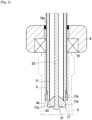
- Each filling head 6 has a spout tip 8 provided with a support seat 9 for the neck of the container.
- the nozzle tip 8 is made by a tube or a cannula whose section is adapted to be able to be introduced into the container 2 through its neck.
- This nozzle end 8 has a lower end 8a ( Fig. 2 ).
- the spout tip 8 is externally equipped with the support seat 9 which is provided with a support seal 10 for the container in the filling position.
- each container 2 is supported by its neck or more precisely by its ring surface 2d on the support seal 10 so as to ensure a seal between the spout end 8 and the neck 2c of the container.
- Each container 2 is thus moved by the handling system 7 to engage the neck around the spout tip 8 and come through its ring surface 2d, resting on the seal 10.
- each filled container 2 is evacuated by the handling system 7 which ensures the delivery of the next container to the filling head.
- the support seat 9 is mounted with the possibility of adjustment relative to the lower end 8a of the spout tip 8 to allow the level of the liquid in the container to be adjusted.
- the support seat 9 is slidably mounted on the nozzle end 8 with a locking system in a predetermined position of all types known per se.
- the nozzle tip 8 may include graduations to facilitate the positioning in a defined position of the support seat 9 relative to the lower end 8a of the nozzle end 8.
- Each spout end 8 is crossed by a filling tube 11 communicating with the storage tank 3 and mounted movable in vertical translation.
- the filling tube 11 passes through the spout tip 8 to delimit with the spout tip, a part 12a of an air return circuit 12 in communication with the interior of the container in order to place it at a value of pressure determined as a function of the filling cycle, as will be explained later in the description.
- the nozzle tip 8 and the filling tube 11 extend coaxially with each other, delimiting between them an annular chamber 12a forming part of the air return circuit 12 ( Fig. 2 ).
- a dynamic sealing system 13 is put in place between the upper part of the nozzle tip 8 and the sliding filling tube 11 in order to close the upper part of the annular chamber 12a.
- This air return circuit 12 also includes a connection pipe 12b with the annular chamber 12a and connected either to atmospheric pressure or to a pressure chamber 14 via a chamber shutter 15.
- the connection pipe 12b is connected via a tank shutter 16, to the sky 3a of the tank 3 whose pressure is maintained equal to atmospheric pressure.
- the air return circuit 12 is placed either at atmospheric pressure (via the tank shutter 16) or at a pressure value greater than atmospheric pressure (via the chamber shutter 15).
- a sealing system 17 ensures the closure of the air return circuit 12 when the filling tube 11 occupies a high position ( Fig. 3 ).
- Such a sealing system 17 can be produced in any appropriate manner. A preferred embodiment will be described later in the description.
- the filling tube 11 has a lower end 11a defining an outlet passage 11b for the liquid.
- the lower end 11a always extends below the support seat 9.
- the filling tube 11 extends thus projecting from the support seat 9 allowing the introduction of the filling tube 11 through its lower end 11a inside the container 2.
- the filling tube 11 is a rigid tube connected to the bottom of tank 3 using a flexible 11c.
- the filling tube 11 is movable in a vertical direction using a movement actuator 18 between a high position and a low position defined in relation to the depth of engagement of the filling tube inside the container.
- the upper position of the filling tube 11 corresponds to the position in a filling cycle, for which the filling tube 11 occupies the highest position.
- This high position can correspond to the leveling position for which the filling tube 11 is engaged inside the container at a depth corresponding to the level of the liquid to be reached inside the container.
- the distance between the support seat 9 and the lower end 11a of the filling tube thus corresponds to the final height of the liquid inside the container 2.
- the lower end 11a of the filling tube is located at the level of the lower end 8a of the spout tip 8 as illustrated in Fig. 2
- the high position of the filling tube 11 can also correspond, according to a preferred embodiment described in detail in the remainder of the description, to a position of the filling tube higher than the leveling position and for which the filling tube 11 closes the air return circuit 12.
- this high position called complete closure illustrated in Fig. 3 the sealing system 17 closes the air return circuit 12 between the lower end 11a of the filling tube and the lower end 8a of the spout tip 8.
- the lower position of the filling tube 11 corresponds to a positioning of the lower end 11a of the filling tube at the level of the bottom 2a of the container.
- the lower end 11a of the filling tube is not in contact with the bottom of the container but is close to the pitted bottom.
- the movement actuator 18 has a movement stroke making it possible to position the lower end 11a of the filling tube 11 between this high position and this low position.
- the actuator 18 is an electric cylinder but it is clear that this actuator can be produced in any suitable manner.
- This actuator 18 comprises an actuating rod 18a sliding in a body 18b and acting on a support 20 supporting the filling tube 11. As shown in the drawings, the upper end of the filling tube 11 is fixed on the support 20 .
- the outlet passage 11b of the filling tube 11 is opened or closed using a closing device 21 of all types.
- the shutter device 21 comprises a rod 22 mounted coaxially inside the filling tube 11.
- This rod 22 is equipped at its lower part with a shutter 23 suitable for opening or closing the outlet passage 11b of the filling tube depending on the position of the rod.
- the rod 22 is mounted movable in translation relative to the filling tube 11 using an actuator 25 which controls at least the blocking of the outlet passage 11b of the filling tube.
- This shutter actuator 25 moves the rod 22 so that the shutter 23 can open or close the outlet passage 11b of the filling tube.
- the rod 22 To move from the open position to the closed position of the outlet passage 11b, the rod 22 is moved upwards relative to the filling tube 11 so that the shutter 23 comes to cooperate with the lower end 11a in order to close its exit passage 11b. To move from the closed position to the open position of the outlet passage 11b, the rod 22 is moved downwards relative to the filling tube 11 so that the shutter 23 does not cooperate with the lower end 11a in order to open its exit passage 11b.
- the stroke of the rod 22 is adapted so that in the open position, the shutter 23 does not reduce the outlet passage 11b of the filling tube 11.
- the rod 22 is guided in sliding by the support 20 on which the shutter actuator 25 is advantageously mounted.
- the shutter actuator 25 is produced by an electric or pneumatic actuator.
- the rod 22 is part of the sealing system 17 which ensures the closure of the air return circuit 12 when the filling tube 11 occupies the high position known as complete closure ( Fig. 3 ) but which ensures the opening of the air return circuit 12 when the filling tube 11 is lowered relative to the spout tip 8 ( Fig. 2 ).
- the lower end of the rod 22 is provided with a seal 17a forming part of the sealing system 17 and extending radially beyond the filling tube 11 to cooperate with the lower end 8a of the nozzle tip 8 to ensure closure of the air return circuit 12.
- the shutter 23 and the seal 17a are made by a common seal carried by the lower end of the rod 22.
- This common seal 23, 17a has a shape frustoconical with its central part closing the filling tube 11 while its peripheral part closes the annular chamber 12a delimited between the filling tube 11 and the spout tip 8.
- This common seal 23, 17a is produced in any case suitable for carrying out the sealing functions described.
- the filling tube 11 is moved upwards relative to the spout tip 8 so that the sealing system 17 ensures closure of the lower part of the annular chamber 12a delimited between the nozzle tip 8 and the filling tube 11. In this closed position illustrated in Fig. 3 , the lower end 11a of the filling tube occupies a higher level compared to the lower end 8a of the spout tip 8.
- the filling machine I also includes a control circuit 28 connected to the chamber shutter 15, to the tank shutter 16, to the movement actuator 18 of the filling tube 11 and to the shutter actuator 25 allowing the opening or closing of the outlet passage of the tube filling 11.
- the control circuit 28 makes it possible to control the operation of the chamber shutter 15, the tank shutter 16, the movement actuator 18 of the filling tube 11 and the shutter actuator 25 to implement a filling process according to the invention.
- the control circuit 28 also controls the sealing system 17 which ensures the closure of the air return circuit 12. In the example illustrated, the sealing system 17 is controlled by the filling tube 11 whose movement is controlled by the movement actuator 18.
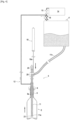
- FIG. 1 illustrates a filling head 6 in a post or pre-filling position in which the outlet passage 11b of the filling tube 11 is closed and the air return circuit 12 is also closed by the closing device 21.
- the tube filling 11 occupies the high position called complete closure also illustrated in Fig. 3 .
- the filling process consists of bringing the neck 2c of the container 2 to rest on the seat 9 of the filling head while engaging the nozzle tip 8 inside the container 2.
- the handling system 7 moves the container 2 to bring its ring surface 2d to rest on the seat 9.
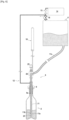
- the method consists of translating the filling tube 11 inside the container 2 from its high position known as complete closure to its low position near the bottom of the container.
- the control circuit 28 thus controls the movement actuator 18 to lower the filling tube 11 until the lower end 11a of the filling tube is located near the bottom of the container.
- the descent of the filling tube 11 leads to releasing the seal between the filling tube 11 and the spout tip 8 since the seal 17a no longer cooperates with the spout tip 8 ( Fig. 2 ).
- the annular chamber 12a is therefore no longer airtight so that the air return circuit 12 is placed in communication with the interior of the container 2.
- the air return circuit 12 is at pressure atmospheric and has a volume determined amount of liquid recovered during the previous filling cycle. Also, the air return circuit 12 empties its liquid along the filling tube 11 during the downward movement of the filling tube 11 inside the container.
- the control circuit 28 controls the shutter actuator 25 to ensure the descent of the rod 22 relative to the filling tube 11 so that the shutter 23 can open the outlet passage 11b of the filling tube. The liquid can thus flow inside the container.
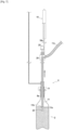
- the air return circuit 12 is placed in communication with the pressure chamber 14 to ensure a slow flow of the liquid.
- the control circuit 28 closes the tank shutter 16 and simultaneously opens the chamber shutter 15.
- the pressure applied inside the container 2 by the pressure chamber 14 and exerted on the liquid leaving the filling tube is such that it makes it possible to reduce the gravity flow of the liquid leaving the filling tube 11, by reducing the speed of the liquid leaving the filling tube 11; the impact of the liquid on the bottom of the container decreases, thus avoiding the creation of turbulence at the start of filling.
- the level of the liquid inside the container 2 thus rises gradually with an upper surface remaining practically flat.
- the air return circuit 12 When the outlet passage 11b of the filling tube 11 is immersed in the liquid, the air return circuit 12 is brought to atmospheric pressure to increase the flow of the liquid.
- the control circuit 28 closes the chamber shutter 15 and simultaneously opens the tank shutter 16 ( Fig. 6 ). It follows that the filling speed is accelerated without affecting the quality of the liquid since the liquid flowing from the outlet passage 11b of the filling tube is submerged.
- the filling tube 11 When the liquid level is such that the outlet passage 11b of the filling tube 11 is immersed in the liquid, then the filling tube 11 is reassembled while retaining the outlet passage 11b of the submerged liquid ( Fig. 7 ).
- the control circuit 28 thus controls the movement actuator 18 to raise the filling tube 11 towards its leveling position while keeping the outlet passage 11b of the filling tube 11 immersed in the liquid. filling continues without affecting the quality of the filling.
- the start of the rise of the filling tube 11 begins after a period determined by experimentation. Likewise, the ascent speed of the filling tube 11 is determined by experiment.
- the filling process ends during an end-of-filling phase occurring when the liquid level approaches the leveling position. Typically, this end of filling phase begins when the liquid level reaches the start of the neck.
- the air return circuit 12 is placed in communication with the pressure chamber 14 to slow down the flow of the liquid ( Fig. 8 ).
- the control circuit 28 closes the tank shutter 16 and simultaneously opens the chamber shutter 15.
- the pressure applied inside the container 2 by the pressure chamber 14 and exerted on the liquid leaving the filling tube is such that it makes it possible to reduce the gravity flow of the liquid leaving the filling tube 11, thus avoiding the creation of turbulence at the end of filling.
- the filling tube 11 continues to move upwards, under the action of the movement actuator 18, to its leveling position.
- the filling tube 11 is moved so that the outlet passage 11b of the filling tube 11 remains submerged.
- the filling tube 11 is moved so that in the leveling position, the lower end 11a of the filling tube is at the level of the lower end 8a of the spout tip 8 ( Fig. 9 ).
- the level of the liquid inside the container 2 thus rises gradually to stabilize at the same level as the lower end 8a of the filling tube.
- the method consists of waiting for the liquid level to stabilize at the lower end 11a of the filling tube 11.
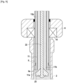
- the liquid continues its path in the air return circuit 12 going up into the annular chamber 12a and even in part of the connection pipe 12b ( Fig. 10 ).
- the method consists of closing the air return circuit 12 as well as outlet passage 11b of the filling tube 11 to stop the exit of the liquid.
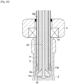
- the control circuit 28 controls the shutter actuator 25 to ensure the rise of the rod 22 relative to the filling tube 11 so that the shutter 23 can close the outlet passage 11b of the filling tube ( Fig. 11 ).
- the control circuit 28 controls the movement actuator 18 to raise the filling tube 11 so that the seal 17a cooperates with the nozzle end 8 to close the air return circuit 12 and in particular the annular chamber 12a.
- the filling tube 11 is raised to the high position known as complete closure as illustrated in Fig. 3 .
- control circuit 28 closes the chamber shutter 15 and opens the tank shutter 16 in order to relieve the pressure in the air return circuit 12.
- the filled container is released from the spout tip 8 after filling using the handling system 7, to allow the engagement of a new container to be filled.
- the object of the invention thus makes it possible to fill and bring to a desired level a container without using a vacuum or a vacuum pump.
- the filling level is carried out by pressure balance when the liquid level reaches the lower end of the filling tube 11.
Landscapes
- Physics & Mathematics (AREA)
- Fluid Mechanics (AREA)
- Filling Of Jars Or Cans And Processes For Cleaning And Sealing Jars (AREA)
- Basic Packing Technique (AREA)
Claims (15)
- Verfahren zum Befüllen von Behältern (2) mithilfe einer Füllflüssigkeit (1), die in einem Tank (3) gelagert wird und mithilfe mindestens eines Füllkopfes (6) ausgegeben wird, der ein Auslaufendstück (8) umfasst, das mit einem Anlagesitz (9) für einen Hals eines Behälters versehen ist, wobei das Auslaufendstück (8) von einem Füllrohr (11) durchquert wird, das mit dem Tank verbunden ist und mit dem Auslaufendstück mindestens einen Teil einer Rückluftleitung (12) begrenzt, wobei das Füllrohr einen Auslasskanal (11b) für die Flüssigkeit begrenzt, der mithilfe einer Verschließvorrichtung (21) geöffnet oder verschlossen wird, wobei das Verfahren die folgenden Schritte zum Befüllen eines Behälters umfasst:- Führen des Halses des Behälters in Anlage an den Sitz (9), indem das Auslaufendstück (8) in das Innere des Behälters (2) eingeführt wird,- Verschieben des Füllrohrs (11) im Inneren des Behälters aus einer oberen Position in eine untere Position in der Nähe des Bodens (2a) des Behälters,- Inverbindungbringen mit dem Inneren des Behälters der Rückluftleitung (12), die auf atmosphärischen Druck gebracht wird, damit sie von ihrer Flüssigkeit entleert wird,- Öffnen, wenn das Füllrohr (11) seine untere Position einnimmt, des Auslasskanals (11b) des Füllrohrs, um das Austreten der Flüssigkeit zu gewährleisten, und Inverbindungbringen der Rückluftleitung (12) mit einer Druckkammer (14), um ein langsames Fließen der Flüssigkeit zu gewährleisten,- wenn der Auslasskanal (11b) des Füllrohrs (11) in die Flüssigkeit eingetaucht ist, Bringen der Rückluftleitung (12) auf atmosphärischen Druck, um das Fließen der Flüssigkeit zu verstärken,- Verlagern des Füllrohrs (11), bei gleichzeitigem Eingetauchthalten des Auslasskanals (11b) für die Flüssigkeit, in Richtung einer Füllhöheneinstellposition, bei welcher das Füllrohr in das Innere des Behälters gemäß einer Tiefe eingeführt ist, die der Füllhöhe der Flüssigkeit im Inneren des Behälters entspricht,- in der Endphase des Befüllens Inverbindungbringen der Rückluftleitung (12) mit der Druckkammer (14), um das Fließen der Flüssigkeit zu verlangsamen, und Verlagern des Füllrohrs (11) bis in seine Füllhöheneinstellposition,- Abwarten der Stabilisierung der Flüssigkeitsfüllhöhe mit einem Flüssigkeitsrücklauf in die Rückluftleitung (12), bevor die Rückluftleitung verschlossen wird,- und Verschließen des Auslasskanals (11b) des Füllrohrs, um das Austreten der Flüssigkeit zu stoppen.
- Verfahren zum Befüllen nach Anspruch 1, bei dem der Behälter (2) nach seinem Befüllen vor dem Einführen eines neuen zu befüllenden Behälters von dem Auslaufendstück (8) getrennt wird.
- Verfahren zum Befüllen nach einem der vorhergehenden Ansprüche, bei dem das Füllrohr (11) verlagert wird, damit sich das untere Ende (11a) des Füllrohrs in der Füllhöheneinstellposition auf Höhe des unteren Endes (8a) des Auslaufendstücks (8) befindet.
- Verfahren zum Befüllen nach einem der vorhergehenden Ansprüche, bei dem der Anlagesitz (9) in einer in Bezug auf das untere Ende (8a) des Auslaufendstücks (8) einstellbaren Position montiert ist, um die Füllhöhe der Flüssigkeit im Inneren des Behälters einzustellen.
- Verfahren zum Befüllen nach einem der vorhergehenden Ansprüche, bei dem das Füllrohr (11) aus seiner Füllhöheneinstellposition bis in die obere Position verlagert wird, um das Verschließen der Rückluftleitung (12) sicherzustellen, das automatisch erfolgt, wenn das Füllrohr aus seiner Füllhöheneinstellposition in die obere Position übergeht.
- Verfahren zum Befüllen nach einem der Ansprüche 1 bis 5, bei dem das Füllrohr (11) so verlagert wird, dass die obere Position der Füllhöheneinstellposition entspricht.
- Verfahren zum Befüllen nach einem der vorhergehenden Ansprüche, bei dem das Verschieben des Füllrohrs (11) im Inneren des Behälters aus der oberen Position in die untere Position das Inverbindungbringen der Rückluftleitung (12) mit dem Inneren des Behälters gewährleistet.
- Verfahren zum Befüllen nach einem der vorhergehenden Ansprüche, bei dem der Behälter (2) zumindest so lange in dichter Anlage an dem Sitz (9) ist, wie der Auslasskanal (11b) des Füllrohrs (11) geöffnet ist.
- Verfahren zum Befüllen nach einem der vorhergehenden Ansprüche, bei dem der Auslasskanal (11b) des Füllrohrs durch einen Verschluss (23) geöffnet oder verschlossen wird, der von einer Stange (22) getragen wird, die in Bezug auf das Rohr verschieblich verlagerbar ist, um den Auslasskanal in Abhängigkeit von der Position der Stange (22) in Bezug auf das Füllrohr (11) zu öffnen oder zu verschließen.
- Maschine zum Befüllen von Behältern (2) mithilfe einer Füllflüssigkeit (1), die in einem Tank (3) gelagert wird, umfassend mindestens einen Füllkopf (6), wobei jeder Füllkopf umfasst:- ein Auslaufendstück (8), das mit einem Anlagesitz (9) für einen Hals eines Behälters versehen ist,- ein Füllrohr (11), das mit dem Tank verbunden ist und das Auslaufendstück (8) durchquert, um mit dem Auslaufendstück einen Teil (12a) einer Rückluftleitung (12) zu begrenzen, die entweder über einen Tankverschluss (16) an den atmosphärischen Druck oder über einen Kammerverschluss (15) an eine Druckkammer (14) angebunden ist, wobei das Füllrohr (11) mithilfe eines Verlagerungsaktors (18) zwischen einerseits einer oberen Position und andererseits einer unteren Position in der Nähe des Bodens des Behälters vertikal verlagerbar ist, wobei das Füllrohr (11) einen Auslasskanal (11b) für die Flüssigkeit begrenzt, der mithilfe einer Verschließvorrichtung (21) geöffnet oder verschlossen wird,- ein Abdichtsystem (17), welches das Verschließen der Rückluftleitung (12) gewährleistet, wenn das Füllrohr (11) seine obere Schließposition einnimmt,- eine Steuerschaltung (28), die mit dem Kammerverschluss (15), mit dem Tankverschluss (16), mit dem Verlagerungsaktor (18), mit der Verschließvorrichtung (21) und mit dem Abdichtsystem (17) verbunden ist, um:* in einer anfänglichen Befüllphase das Füllrohr (11) aus seiner oberen Schließposition in seine untere Position zu verlagern und die Verschließvorrichtung (21) anzusteuern, um den Auslasskanal (11b) des Füllrohrs (11) zu öffnen und die Rückluftleitung (12) mit der Druckkammer (14) in Verbindung zu bringen,* wenn der Auslasskanal (11b) des Füllrohrs in die Flüssigkeit eingetaucht ist, die Rückluftleitung (12) auf atmosphärischen Druck zu bringen und das Füllrohr (11) in Richtung seiner Füllhöheneinstellposition zu verlagern, wobei der Auslasskanal (11b) für die Flüssigkeit eingetaucht gehalten wird,* in der Endphase des Befüllens die Rückluftleitung (12) mit der Druckkammer (14) in Verbindung zu bringen und das Füllrohr (11) in eine Füllhöheneinstellposition der Flüssigkeit im Inneren des Behälters zu führen, mit einem Flüssigkeitsrücklauf in die Rückluftleitung (12), das Abdichtsystem (17) anzusteuern, um die Rückluftleitung zu verschließen, und die Verschließvorrichtung (21) anzusteuern, um den Auslasskanal für die Flüssigkeit zu verschließen.
- Maschine zum Befüllen nach dem vorhergehenden Anspruch, bei der die Verschließvorrichtung (21) eine Stange (22) umfasst, die im Inneren des Füllrohrs (11) montiert ist und an ihrem unteren Teil mit einem Verschluss (23) ausgestattet ist und in Bezug auf das Füllrohr (11) mithilfe eines Füllaktors (25) verschieblich verlagerbar ist, damit der Verschluss (23) den Auslasskanal (11b) des Füllrohrs (11) in Abhängigkeit von der Position der Stange öffnen oder verschließen kann.
- Maschine zum Befüllen nach einem der Ansprüche 10 oder 11, bei der das Abdichtsystem (17) eine Dichtung (17a) umfasst, die von der Stange (22) getragen wird, um die Rückluftleitung (12) zu verschließen, wenn das Füllrohr (11) aus seiner Füllhöheneinstellposition in seine obere Schließposition übergeht.
- Maschine zum Befüllen nach einem der Ansprüche 10 bis 12, bei welcher der Anlagesitz (9) mit einer Einstellmöglichkeit in Bezug auf das untere Ende (8a) des Auslaufendstücks (8) montiert ist, um das Einstellen der Füllhöhe der Flüssigkeit in dem Behälter zu ermöglichen.
- Maschine zum Befüllen nach einem der Ansprüche 11 bis 13, bei der das Füllrohr (11) mit einer Halterung (20) für die Stange (22) und für den Füllaktor (25) versehen ist.
- Maschine zum Befüllen nach einem der Ansprüche 10 bis 14, wobei sie ein Handlingsystem (7) für die Behälter umfasst, das es ermöglicht, jeden Behälter (2) in das Auslaufendstück (8) einzuführen und jeden der Behälter nach deren Befüllen zu trennen.
Applications Claiming Priority (2)
| Application Number | Priority Date | Filing Date | Title |
|---|---|---|---|
| FR1910323A FR3101074B1 (fr) | 2019-09-19 | 2019-09-19 | Procédé et machine pour remplir un récipient à un niveau souhaité de liquide |
| PCT/FR2020/051605 WO2021053297A1 (fr) | 2019-09-19 | 2020-09-17 | Procédé et machine pour remplir un récipient à un niveau souhaité de liquide |
Publications (3)
| Publication Number | Publication Date |
|---|---|
| EP4031479A1 EP4031479A1 (de) | 2022-07-27 |
| EP4031479C0 EP4031479C0 (de) | 2023-10-11 |
| EP4031479B1 true EP4031479B1 (de) | 2023-10-11 |
Family
ID=69172948
Family Applications (1)
| Application Number | Title | Priority Date | Filing Date |
|---|---|---|---|
| EP20820483.4A Active EP4031479B1 (de) | 2019-09-19 | 2020-09-17 | Verfahren und maschine zum befüllen eines behälters mit einem gewünschten flüssigkeitsniveau |
Country Status (4)
| Country | Link |
|---|---|
| US (1) | US11745992B2 (de) |
| EP (1) | EP4031479B1 (de) |
| FR (1) | FR3101074B1 (de) |
| WO (1) | WO2021053297A1 (de) |
Families Citing this family (1)
| Publication number | Priority date | Publication date | Assignee | Title |
|---|---|---|---|---|
| IT202100016190A1 (it) * | 2021-06-21 | 2022-12-21 | Gai Macch S P A | Metodo e gruppo di riempimento di una bottiglia con un liquido alimentare |
Family Cites Families (20)
| Publication number | Priority date | Publication date | Assignee | Title |
|---|---|---|---|---|
| US1978002A (en) | 1931-04-17 | 1934-10-23 | Horix Mfg Company | Filling machine and method of filling containers |
| US2794453A (en) * | 1955-11-14 | 1957-06-04 | F Wenge Ets | Filling heads for bottling machine |
| GB972916A (en) * | 1961-02-15 | 1964-10-21 | Karl Kiefer Machine Company | Filling head for filling containers such as bottles |
| DE1185497B (de) | 1961-06-30 | 1965-01-14 | Holstein & Kappert Maschf | Ventilgesteuertes Fuellorgan fuer Gegendruckflaschenfueller |
| DE1432361A1 (de) * | 1964-10-06 | 1969-09-04 | Holstein & Kappert Maschf | Verfahren zum Abfuellen von Bier oder anderen kohlensaeurehaltigen Getraenken |
| US3516455A (en) * | 1967-05-01 | 1970-06-23 | Automatic Sprinkler Corp | Container-filling apparatus |
| DE2234120C3 (de) * | 1972-07-12 | 1979-08-09 | Seitz-Werke Gmbh, 6550 Bad Kreuznach | Füllelement mit langem Fallrohr für Mehrkammer-Gegendruckfüllmaschinen |
| FR2213902B1 (de) * | 1973-01-17 | 1977-08-05 | Chelle Ets | |
| US4363339A (en) * | 1981-04-09 | 1982-12-14 | Barry-Wehmiller Company | Filling valve arrangement for counter-pressure container filling apparatus |
| EP0103484A3 (de) * | 1982-09-13 | 1984-05-02 | Laub, Herman, III | Füllmaschine für schäumende Flüssigkeiten |
| US4693054A (en) * | 1984-11-06 | 1987-09-15 | Anheuser-Busch, Incorporated | Process for filling beer into containers |
| US5255720A (en) * | 1990-04-03 | 1993-10-26 | Mcpherson Dripless Systems Co., Inc. | Method and apparatus for dripless filling of containers |
| EP0614850A1 (de) * | 1993-03-10 | 1994-09-14 | KHS Maschinen- und Anlagenbau Aktiengesellschaft | Füllelement für Füllmaschinen zum Abfüllen eines flüssigen Füllgutes in Flaschen oder dgl. Behälter |
| DE4402980C1 (de) * | 1994-02-01 | 1995-06-01 | Khs Masch & Anlagenbau Ag | Füllsystem zum Abfüllen eines flüssigen Füllgutes in Flaschen, Dosen oder dgl. Behälter |
| IT1392774B1 (it) * | 2009-02-13 | 2012-03-23 | Four One S R L | Apparato e procedimento per il riempimento di un contenitore. |
| DE102010028953A1 (de) * | 2010-05-12 | 2011-11-17 | Krones Ag | Befüllvorrichtung |
| FR2994691B1 (fr) * | 2012-08-24 | 2014-09-05 | Philippe Perrier | Procede et machine pour le remplissage de recipients |
| US20170225933A1 (en) | 2014-08-29 | 2017-08-10 | Dr Tech S.R.L | Method for filling bottles with wine |
| ITUA20164306A1 (it) * | 2016-06-13 | 2017-12-13 | Dr Tech S R L | Dispositivo e metodo per il riempimento di contenitori con un liquido, in particolare per l’imbottigliamento |
| DE102018131077A1 (de) * | 2018-12-05 | 2020-06-10 | Krones Ag | Vorrichtung und Verfahren zum Abfüllen eines Füllprodukts in einen zu befüllenden Behälter in einer Getränkeabfüllanlage |
-
2019
- 2019-09-19 FR FR1910323A patent/FR3101074B1/fr active Active
-
2020
- 2020-09-17 US US17/642,970 patent/US11745992B2/en active Active
- 2020-09-17 EP EP20820483.4A patent/EP4031479B1/de active Active
- 2020-09-17 WO PCT/FR2020/051605 patent/WO2021053297A1/fr not_active Ceased
Also Published As
| Publication number | Publication date |
|---|---|
| FR3101074B1 (fr) | 2021-10-01 |
| EP4031479C0 (de) | 2023-10-11 |
| FR3101074A1 (fr) | 2021-03-26 |
| US20220332560A1 (en) | 2022-10-20 |
| EP4031479A1 (de) | 2022-07-27 |
| WO2021053297A1 (fr) | 2021-03-25 |
| US11745992B2 (en) | 2023-09-05 |
Similar Documents
| Publication | Publication Date | Title |
|---|---|---|
| EP2595792B1 (de) | Vefahren zur herstellung eines behälters mittes blasen und befüllen | |
| FR2509658A2 (fr) | Procede de fabrication de pieces moulees a partir de composes aptes a s'ecouler et dispositif pour sa mise en oeuvre | |
| EP2919963B1 (de) | Verfahren zur herstellung von behältern mit verzögertem kartonierungsbetrieb | |
| EP2888195B1 (de) | Behälterfüllmaschine und -verfahren | |
| EP1311453B1 (de) | Abfüllkopf mit sprinklerstrahl und abfüllmschine mit solchen köpfen | |
| EP2049400B1 (de) | Verfahren und vorrichtung zur tankbefüllung mit einem flüssigen produkt | |
| FR2569393A1 (fr) | Procede et dispositif pour remplir des bouteilles ou recipients analogues | |
| EP4031479B1 (de) | Verfahren und maschine zum befüllen eines behälters mit einem gewünschten flüssigkeitsniveau | |
| EP3468910B1 (de) | Vorrichtung und verfahren zum füllen von behältern mit einer flüssigkeit, insbesondere zum abfüllen von flaschen | |
| EP2758332B1 (de) | Verfahren und ausgiesser für eine flüssigkeitsbefüllung mit konstantem pegel | |
| EP3728052B1 (de) | Verfahren zur umkehrung der bodenwand eines kunststoffbehälters, vorrichtung zur durchführung des verfahren und verwendung der vorrichtung zur durchführung des verfahrens | |
| FR2526412A1 (fr) | Procede et dispositif pour le remplissage de bouteilles | |
| FR2528450A1 (fr) | Procede et dispositif pour incorporer une dose de liqueur dans une bouteille de vin champagnise | |
| FR2521224A1 (fr) | Procede et dispositif pour l'addition d'une quantite predeterminee d'un second liquide (liquide a doser) a un premier liquide qui se trouve dans un recipient | |
| EP0179678A1 (de) | Verfahren und Gerät zum Übertragen und Dosieren spröder Teilchen mit hohem Rhythmus z.B. zum Einbringen in einen Behälter | |
| FR3109743A1 (fr) | Organe de type « appui buvant », tuyère et installation de soufflage de corps creux | |
| FR2852944A1 (fr) | Procede et dispositif de remplissage volumetrique d'un recipient tel qu'une bouteille au moyen d'un liquide. | |
| FR2752415A1 (fr) | Procede et dispositif de controle de l'atmosphere d'une bouteille dans une machine de remplissage | |
| EP4674804A1 (de) | Automatischer spender für flüssigkeiten | |
| FR2734253A1 (fr) | Procede et dispositifs pour l'introduction complete d'un bouchon dans un recipient, avec maitrise de la pression apres bouchage | |
| FR2767126A1 (fr) | Procede et dispositif pour assurer le remplissage et la mise a niveau d'un liquide contenu dans un recipient et machine equipee d'un tel dispositif | |
| BE539227A (de) | ||
| FR2564936A1 (fr) | Robinet de mise a niveau | |
| BE438664A (de) | ||
| FR3022897A1 (fr) | Dispositif de distribution d'un liquide |
Legal Events
| Date | Code | Title | Description |
|---|---|---|---|
| STAA | Information on the status of an ep patent application or granted ep patent |
Free format text: STATUS: UNKNOWN |
|
| STAA | Information on the status of an ep patent application or granted ep patent |
Free format text: STATUS: THE INTERNATIONAL PUBLICATION HAS BEEN MADE |
|
| PUAI | Public reference made under article 153(3) epc to a published international application that has entered the european phase |
Free format text: ORIGINAL CODE: 0009012 |
|
| STAA | Information on the status of an ep patent application or granted ep patent |
Free format text: STATUS: REQUEST FOR EXAMINATION WAS MADE |
|
| 17P | Request for examination filed |
Effective date: 20220228 |
|
| AK | Designated contracting states |
Kind code of ref document: A1 Designated state(s): AL AT BE BG CH CY CZ DE DK EE ES FI FR GB GR HR HU IE IS IT LI LT LU LV MC MK MT NL NO PL PT RO RS SE SI SK SM TR |
|
| DAV | Request for validation of the european patent (deleted) | ||
| DAX | Request for extension of the european patent (deleted) | ||
| GRAP | Despatch of communication of intention to grant a patent |
Free format text: ORIGINAL CODE: EPIDOSNIGR1 |
|
| STAA | Information on the status of an ep patent application or granted ep patent |
Free format text: STATUS: GRANT OF PATENT IS INTENDED |
|
| INTG | Intention to grant announced |
Effective date: 20230508 |
|
| RIN1 | Information on inventor provided before grant (corrected) |
Inventor name: PERRIER, PHILIPPE |
|
| P01 | Opt-out of the competence of the unified patent court (upc) registered |
Effective date: 20230502 |
|
| P02 | Opt-out of the competence of the unified patent court (upc) changed |
Effective date: 20230503 |
|
| GRAS | Grant fee paid |
Free format text: ORIGINAL CODE: EPIDOSNIGR3 |
|
| GRAA | (expected) grant |
Free format text: ORIGINAL CODE: 0009210 |
|
| STAA | Information on the status of an ep patent application or granted ep patent |
Free format text: STATUS: THE PATENT HAS BEEN GRANTED |
|
| AK | Designated contracting states |
Kind code of ref document: B1 Designated state(s): AL AT BE BG CH CY CZ DE DK EE ES FI FR GB GR HR HU IE IS IT LI LT LU LV MC MK MT NL NO PL PT RO RS SE SI SK SM TR |
|
| REG | Reference to a national code |
Ref country code: GB Ref legal event code: FG4D Free format text: NOT ENGLISH |
|
| REG | Reference to a national code |
Ref country code: CH Ref legal event code: EP |
|
| REG | Reference to a national code |
Ref country code: DE Ref legal event code: R096 Ref document number: 602020019213 Country of ref document: DE |
|
| REG | Reference to a national code |
Ref country code: IE Ref legal event code: FG4D Free format text: LANGUAGE OF EP DOCUMENT: FRENCH |
|
| P04 | Withdrawal of opt-out of the competence of the unified patent court (upc) registered |
Effective date: 20231113 |
|
| U01 | Request for unitary effect filed |
Effective date: 20231110 |
|
| U07 | Unitary effect registered |
Designated state(s): AT BE BG DE DK EE FI FR IT LT LU LV MT NL PT SE SI Effective date: 20231116 |
|
| PG25 | Lapsed in a contracting state [announced via postgrant information from national office to epo] |
Ref country code: GR Free format text: LAPSE BECAUSE OF FAILURE TO SUBMIT A TRANSLATION OF THE DESCRIPTION OR TO PAY THE FEE WITHIN THE PRESCRIBED TIME-LIMIT Effective date: 20240112 |
|
| PG25 | Lapsed in a contracting state [announced via postgrant information from national office to epo] |
Ref country code: IS Free format text: LAPSE BECAUSE OF FAILURE TO SUBMIT A TRANSLATION OF THE DESCRIPTION OR TO PAY THE FEE WITHIN THE PRESCRIBED TIME-LIMIT Effective date: 20240211 |
|
| PG25 | Lapsed in a contracting state [announced via postgrant information from national office to epo] |
Ref country code: ES Free format text: LAPSE BECAUSE OF FAILURE TO SUBMIT A TRANSLATION OF THE DESCRIPTION OR TO PAY THE FEE WITHIN THE PRESCRIBED TIME-LIMIT Effective date: 20231011 |
|
| PG25 | Lapsed in a contracting state [announced via postgrant information from national office to epo] |
Ref country code: IS Free format text: LAPSE BECAUSE OF FAILURE TO SUBMIT A TRANSLATION OF THE DESCRIPTION OR TO PAY THE FEE WITHIN THE PRESCRIBED TIME-LIMIT Effective date: 20240211 Ref country code: GR Free format text: LAPSE BECAUSE OF FAILURE TO SUBMIT A TRANSLATION OF THE DESCRIPTION OR TO PAY THE FEE WITHIN THE PRESCRIBED TIME-LIMIT Effective date: 20240112 Ref country code: ES Free format text: LAPSE BECAUSE OF FAILURE TO SUBMIT A TRANSLATION OF THE DESCRIPTION OR TO PAY THE FEE WITHIN THE PRESCRIBED TIME-LIMIT Effective date: 20231011 |
|
| PG25 | Lapsed in a contracting state [announced via postgrant information from national office to epo] |
Ref country code: RS Free format text: LAPSE BECAUSE OF FAILURE TO SUBMIT A TRANSLATION OF THE DESCRIPTION OR TO PAY THE FEE WITHIN THE PRESCRIBED TIME-LIMIT Effective date: 20231011 Ref country code: PL Free format text: LAPSE BECAUSE OF FAILURE TO SUBMIT A TRANSLATION OF THE DESCRIPTION OR TO PAY THE FEE WITHIN THE PRESCRIBED TIME-LIMIT Effective date: 20231011 Ref country code: NO Free format text: LAPSE BECAUSE OF FAILURE TO SUBMIT A TRANSLATION OF THE DESCRIPTION OR TO PAY THE FEE WITHIN THE PRESCRIBED TIME-LIMIT Effective date: 20240111 Ref country code: HR Free format text: LAPSE BECAUSE OF FAILURE TO SUBMIT A TRANSLATION OF THE DESCRIPTION OR TO PAY THE FEE WITHIN THE PRESCRIBED TIME-LIMIT Effective date: 20231011 |
|
| REG | Reference to a national code |
Ref country code: DE Ref legal event code: R097 Ref document number: 602020019213 Country of ref document: DE |
|
| PG25 | Lapsed in a contracting state [announced via postgrant information from national office to epo] |
Ref country code: CZ Free format text: LAPSE BECAUSE OF FAILURE TO SUBMIT A TRANSLATION OF THE DESCRIPTION OR TO PAY THE FEE WITHIN THE PRESCRIBED TIME-LIMIT Effective date: 20231011 |
|
| PG25 | Lapsed in a contracting state [announced via postgrant information from national office to epo] |
Ref country code: SK Free format text: LAPSE BECAUSE OF FAILURE TO SUBMIT A TRANSLATION OF THE DESCRIPTION OR TO PAY THE FEE WITHIN THE PRESCRIBED TIME-LIMIT Effective date: 20231011 |
|
| PG25 | Lapsed in a contracting state [announced via postgrant information from national office to epo] |
Ref country code: SM Free format text: LAPSE BECAUSE OF FAILURE TO SUBMIT A TRANSLATION OF THE DESCRIPTION OR TO PAY THE FEE WITHIN THE PRESCRIBED TIME-LIMIT Effective date: 20231011 Ref country code: SK Free format text: LAPSE BECAUSE OF FAILURE TO SUBMIT A TRANSLATION OF THE DESCRIPTION OR TO PAY THE FEE WITHIN THE PRESCRIBED TIME-LIMIT Effective date: 20231011 Ref country code: RO Free format text: LAPSE BECAUSE OF FAILURE TO SUBMIT A TRANSLATION OF THE DESCRIPTION OR TO PAY THE FEE WITHIN THE PRESCRIBED TIME-LIMIT Effective date: 20231011 Ref country code: CZ Free format text: LAPSE BECAUSE OF FAILURE TO SUBMIT A TRANSLATION OF THE DESCRIPTION OR TO PAY THE FEE WITHIN THE PRESCRIBED TIME-LIMIT Effective date: 20231011 |
|
| U20 | Renewal fee for the european patent with unitary effect paid |
Year of fee payment: 5 Effective date: 20240701 |
|
| PLBE | No opposition filed within time limit |
Free format text: ORIGINAL CODE: 0009261 |
|
| STAA | Information on the status of an ep patent application or granted ep patent |
Free format text: STATUS: NO OPPOSITION FILED WITHIN TIME LIMIT |
|
| 26N | No opposition filed |
Effective date: 20240712 |
|
| P05 | Withdrawal of opt-out of the competence of the unified patent court (upc) changed |
Free format text: CASE NUMBER: APP_586997/2023 Effective date: 20231116 |
|
| PG25 | Lapsed in a contracting state [announced via postgrant information from national office to epo] |
Ref country code: MC Free format text: LAPSE BECAUSE OF FAILURE TO SUBMIT A TRANSLATION OF THE DESCRIPTION OR TO PAY THE FEE WITHIN THE PRESCRIBED TIME-LIMIT Effective date: 20231011 |
|
| REG | Reference to a national code |
Ref country code: CH Ref legal event code: PL |
|
| PG25 | Lapsed in a contracting state [announced via postgrant information from national office to epo] |
Ref country code: CH Free format text: LAPSE BECAUSE OF NON-PAYMENT OF DUE FEES Effective date: 20240930 |
|
| PG25 | Lapsed in a contracting state [announced via postgrant information from national office to epo] |
Ref country code: IE Free format text: LAPSE BECAUSE OF NON-PAYMENT OF DUE FEES Effective date: 20240917 |
|
| U20 | Renewal fee for the european patent with unitary effect paid |
Year of fee payment: 6 Effective date: 20250630 |
|
| PGFP | Annual fee paid to national office [announced via postgrant information from national office to epo] |
Ref country code: GB Payment date: 20250919 Year of fee payment: 6 |
|
| PG25 | Lapsed in a contracting state [announced via postgrant information from national office to epo] |
Ref country code: CY Free format text: LAPSE BECAUSE OF FAILURE TO SUBMIT A TRANSLATION OF THE DESCRIPTION OR TO PAY THE FEE WITHIN THE PRESCRIBED TIME-LIMIT; INVALID AB INITIO Effective date: 20200917 |
|
| PG25 | Lapsed in a contracting state [announced via postgrant information from national office to epo] |
Ref country code: HU Free format text: LAPSE BECAUSE OF FAILURE TO SUBMIT A TRANSLATION OF THE DESCRIPTION OR TO PAY THE FEE WITHIN THE PRESCRIBED TIME-LIMIT; INVALID AB INITIO Effective date: 20200917 |