EP0179678A1 - Verfahren und Gerät zum Übertragen und Dosieren spröder Teilchen mit hohem Rhythmus z.B. zum Einbringen in einen Behälter - Google Patents
Verfahren und Gerät zum Übertragen und Dosieren spröder Teilchen mit hohem Rhythmus z.B. zum Einbringen in einen Behälter Download PDFInfo
- Publication number
- EP0179678A1 EP0179678A1 EP85401704A EP85401704A EP0179678A1 EP 0179678 A1 EP0179678 A1 EP 0179678A1 EP 85401704 A EP85401704 A EP 85401704A EP 85401704 A EP85401704 A EP 85401704A EP 0179678 A1 EP0179678 A1 EP 0179678A1
- Authority
- EP
- European Patent Office
- Prior art keywords
- transfer
- solid particles
- metering
- compartment
- chamber
- Prior art date
- Legal status (The legal status is an assumption and is not a legal conclusion. Google has not performed a legal analysis and makes no representation as to the accuracy of the status listed.)
- Granted
Links
- 239000002245 particle Substances 0.000 title claims abstract description 70
- 238000000034 method Methods 0.000 title claims abstract description 17
- 230000001131 transforming effect Effects 0.000 title 1
- 239000007787 solid Substances 0.000 claims abstract description 63
- 238000012546 transfer Methods 0.000 claims abstract description 63
- 238000005192 partition Methods 0.000 claims abstract description 10
- 239000007788 liquid Substances 0.000 claims description 23
- 235000014101 wine Nutrition 0.000 claims description 19
- 240000004808 Saccharomyces cerevisiae Species 0.000 claims description 17
- 244000005700 microbiome Species 0.000 claims description 17
- 238000003780 insertion Methods 0.000 claims description 15
- 230000037431 insertion Effects 0.000 claims description 15
- 239000000725 suspension Substances 0.000 claims description 15
- 238000000855 fermentation Methods 0.000 claims description 14
- 230000004151 fermentation Effects 0.000 claims description 14
- 239000011324 bead Substances 0.000 claims description 11
- 235000019993 champagne Nutrition 0.000 claims description 7
- 238000013519 translation Methods 0.000 claims description 7
- 235000010410 calcium alginate Nutrition 0.000 claims description 6
- 229960002681 calcium alginate Drugs 0.000 claims description 6
- 239000000648 calcium alginate Substances 0.000 claims description 6
- OKHHGHGGPDJQHR-YMOPUZKJSA-L calcium;(2s,3s,4s,5s,6r)-6-[(2r,3s,4r,5s,6r)-2-carboxy-6-[(2r,3s,4r,5s,6r)-2-carboxylato-4,5,6-trihydroxyoxan-3-yl]oxy-4,5-dihydroxyoxan-3-yl]oxy-3,4,5-trihydroxyoxane-2-carboxylate Chemical compound [Ca+2].O[C@@H]1[C@H](O)[C@H](O)O[C@@H](C([O-])=O)[C@H]1O[C@H]1[C@@H](O)[C@@H](O)[C@H](O[C@H]2[C@H]([C@@H](O)[C@H](O)[C@H](O2)C([O-])=O)O)[C@H](C(O)=O)O1 OKHHGHGGPDJQHR-YMOPUZKJSA-L 0.000 claims description 6
- 238000006073 displacement reaction Methods 0.000 claims description 5
- 235000019674 grape juice Nutrition 0.000 claims description 4
- 229920000642 polymer Polymers 0.000 claims description 3
- 230000001360 synchronised effect Effects 0.000 claims description 3
- 238000007599 discharging Methods 0.000 claims description 2
- 235000013405 beer Nutrition 0.000 claims 1
- 239000011261 inert gas Substances 0.000 claims 1
- 230000001681 protective effect Effects 0.000 claims 1
- 239000000463 material Substances 0.000 description 6
- 239000000243 solution Substances 0.000 description 5
- 238000004140 cleaning Methods 0.000 description 3
- 238000009826 distribution Methods 0.000 description 3
- 238000005070 sampling Methods 0.000 description 3
- FHVDTGUDJYJELY-UHFFFAOYSA-N 6-{[2-carboxy-4,5-dihydroxy-6-(phosphanyloxy)oxan-3-yl]oxy}-4,5-dihydroxy-3-phosphanyloxane-2-carboxylic acid Chemical compound O1C(C(O)=O)C(P)C(O)C(O)C1OC1C(C(O)=O)OC(OP)C(O)C1O FHVDTGUDJYJELY-UHFFFAOYSA-N 0.000 description 2
- 229940072056 alginate Drugs 0.000 description 2
- 235000010443 alginic acid Nutrition 0.000 description 2
- 229920000615 alginic acid Polymers 0.000 description 2
- 239000012530 fluid Substances 0.000 description 2
- 238000012986 modification Methods 0.000 description 2
- 230000004048 modification Effects 0.000 description 2
- 238000005096 rolling process Methods 0.000 description 2
- 238000000926 separation method Methods 0.000 description 2
- 238000011144 upstream manufacturing Methods 0.000 description 2
- 230000002159 abnormal effect Effects 0.000 description 1
- 230000006978 adaptation Effects 0.000 description 1
- 235000016127 added sugars Nutrition 0.000 description 1
- 238000013019 agitation Methods 0.000 description 1
- 230000007423 decrease Effects 0.000 description 1
- 235000011389 fruit/vegetable juice Nutrition 0.000 description 1
- 239000011521 glass Substances 0.000 description 1
- 230000005484 gravity Effects 0.000 description 1
- 239000008240 homogeneous mixture Substances 0.000 description 1
- -1 microorganisms Chemical compound 0.000 description 1
- 239000012487 rinsing solution Substances 0.000 description 1
- 230000000630 rising effect Effects 0.000 description 1
- 238000003756 stirring Methods 0.000 description 1
- 238000003860 storage Methods 0.000 description 1
Images


Classifications
-
- C—CHEMISTRY; METALLURGY
- C12—BIOCHEMISTRY; BEER; SPIRITS; WINE; VINEGAR; MICROBIOLOGY; ENZYMOLOGY; MUTATION OR GENETIC ENGINEERING
- C12G—WINE; PREPARATION THEREOF; ALCOHOLIC BEVERAGES; PREPARATION OF ALCOHOLIC BEVERAGES NOT PROVIDED FOR IN SUBCLASSES C12C OR C12H
- C12G1/00—Preparation of wine or sparkling wine
- C12G1/06—Preparation of sparkling wine; Impregnation of wine with carbon dioxide
-
- B—PERFORMING OPERATIONS; TRANSPORTING
- B65—CONVEYING; PACKING; STORING; HANDLING THIN OR FILAMENTARY MATERIAL
- B65B—MACHINES, APPARATUS OR DEVICES FOR, OR METHODS OF, PACKAGING ARTICLES OR MATERIALS; UNPACKING
- B65B1/00—Packaging fluent solid material, e.g. powders, granular or loose fibrous material, loose masses of small articles, in individual containers or receptacles, e.g. bags, sacks, boxes, cartons, cans, or jars
- B65B1/30—Devices or methods for controlling or determining the quantity or quality or the material fed or filled
- B65B1/36—Devices or methods for controlling or determining the quantity or quality or the material fed or filled by volumetric devices or methods
- B65B1/363—Devices or methods for controlling or determining the quantity or quality or the material fed or filled by volumetric devices or methods with measuring pockets moving in an endless path
-
- B—PERFORMING OPERATIONS; TRANSPORTING
- B65—CONVEYING; PACKING; STORING; HANDLING THIN OR FILAMENTARY MATERIAL
- B65B—MACHINES, APPARATUS OR DEVICES FOR, OR METHODS OF, PACKAGING ARTICLES OR MATERIALS; UNPACKING
- B65B3/00—Packaging plastic material, semiliquids, liquids or mixed solids and liquids, in individual containers or receptacles, e.g. bags, sacks, boxes, cartons, cans, or jars
- B65B3/26—Methods or devices for controlling the quantity of the material fed or filled
- B65B3/30—Methods or devices for controlling the quantity of the material fed or filled by volumetric measurement
-
- G—PHYSICS
- G01—MEASURING; TESTING
- G01F—MEASURING VOLUME, VOLUME FLOW, MASS FLOW OR LIQUID LEVEL; METERING BY VOLUME
- G01F11/00—Apparatus requiring external operation adapted at each repeated and identical operation to measure and separate a predetermined volume of fluid or fluent solid material from a supply or container, without regard to weight, and to deliver it
- G01F11/10—Apparatus requiring external operation adapted at each repeated and identical operation to measure and separate a predetermined volume of fluid or fluent solid material from a supply or container, without regard to weight, and to deliver it with measuring chambers moved during operation
- G01F11/12—Apparatus requiring external operation adapted at each repeated and identical operation to measure and separate a predetermined volume of fluid or fluent solid material from a supply or container, without regard to weight, and to deliver it with measuring chambers moved during operation of the valve type, i.e. the separating being effected by fluid-tight or powder-tight movements
- G01F11/14—Apparatus requiring external operation adapted at each repeated and identical operation to measure and separate a predetermined volume of fluid or fluent solid material from a supply or container, without regard to weight, and to deliver it with measuring chambers moved during operation of the valve type, i.e. the separating being effected by fluid-tight or powder-tight movements wherein the measuring chamber reciprocates
- G01F11/18—Apparatus requiring external operation adapted at each repeated and identical operation to measure and separate a predetermined volume of fluid or fluent solid material from a supply or container, without regard to weight, and to deliver it with measuring chambers moved during operation of the valve type, i.e. the separating being effected by fluid-tight or powder-tight movements wherein the measuring chamber reciprocates for fluent solid material
Definitions
- the present invention relates to a method and an apparatus for transferring and / or dosing fragile solid particles, in particular at a high rate for any use, for example insertion into a container, in particular a bottle, said fragile solid particles preferably being alginate beads including microorganisms, in particular yeasts, with a view to carrying out in particular the fermentation of a liquid capable of fermenting, such as grape juice, wine, preferably champagne wine.
- a liquid capable of fermenting such as grape juice, wine, preferably champagne wine.
- yeasts are mixed with wine with added sugar in large tanks and this homogeneous mixture is injected into the bottles by gravity and / or depression and / or overpressure by metering devices volumetric or continuous using mechanical components, for example drawers, valves, worms or valves.
- the Applicant has highlighted a new technical problem posed by this inclusion of yeasts and which lies in the need not to deteriorate the inclusion material in the step of transferring beads including yeasts or other microorganisms in the bottles. or other fermentation vessels, so as not to release yeasts or other microorganisms in the medium to be fermented such as wine or grape juice because this release of yeasts or other microorganisms would negate the advantage of the inclusion process which consists in the easy separation of yeasts or other fermentation microorganisms from the fermented medium and, on the other hand, in order to avoid abnormal turbidity which is harmful for the marketing of the product or the conservation thereof, in particular for wine or champagne.
- the present invention therefore aims to solve this new technical problem.
- the present invention also aims to provide a solution solving this new technical problem in an extremely simple manner, which does not deteriorate the inclusion material under any circumstances during the step of transferring the material d inclusion in the form of beads including yeasts or other fermentation microorganisms.
- the invention also aims to provide a solution allowing a very precise dosage of the amount of yeast or microorganism transferred into a container, in particular a bottle.
- the present invention also aims to provide a solution which is applicable in the general case of the transfer and / or metering of fragile solid particles, without damaging them, and at a high rate.
- the present invention provides a method of transfer and / or metering of fragile solid particles without damaging them, in particular at high speed, for any use, for example insertion into a container.
- a bottle characterized in that it comprises:
- the insertion, suction, displacement and delivery operations are carried out automatically by the provision of suitable control means, preferably mechanical control means.
- control means comprise cam elements cooperating with cam follower elements.
- the particles are beads spheres of calcium alginate including fermentation microorganisms, in particular in suspension in a liquid capable of fermenting, in particular chosen from wine, preferably champagne wine, or grape juice.
- the insertion is preferably carried out in bottles.
- the solid particles are substituted by polymer beads of density higher or slightly higher than that of the liquid capable of fermenting by the microorganisms included.
- the present invention also relates to an apparatus for transferring and / or dosing fragile solid particles, in particular at high speed, without damaging them, for any use, for example insertion into a container, in particular a bottle, characterized in that it comprises a transfer and / or metering device comprising an elongated chamber comprising a side wall, preferably essentially cylindrical, defining said chamber, said chamber having an open lower end and a closed upper end comprising a transverse partition provided with at least one orifice, preferably a plurality of orifices, of diameter less than the diameter of said solid particles, and arranged substantially perpendicular to said side wall and at a distance from the ends of said chamber so as to subdivide said room in two compartments communicating by said orif ices, a first transfer and / or metering compartment proper ending at its lower end by an opening defined by the open lower end of said chamber, and a second compartment called suction or discharge cooperating with means d 'suction or discharge; and means actu
- the suction or delivery means comprise a piston arranged in the second so-called suction or delivery compartment, slidingly relative to said compartment thereby forming a body of cylinder; said piston being actuated by the aforementioned actuation means.
- the actuation means comprise mechanical control means.
- these mechanical control means comprise cam elements and cam follower elements.
- the transfer and / or metering device is mounted displaceable in vertical translation and in rotation relative to a frame, between a position for sampling or aspiration of the solid particles suspended in an appropriate reservoir, at a position for discharging the solid particles into any container, in particular a bottle.
- the apparatus comprises a barrel mounted to rotate relative to the chassis and provided with a plurality of transfer and / or metering devices spaced apart at a determined pitch; means for conveying receptacles for receiving solid particles, in particular bottles, facing each transfer and / or metering device.
- These conveying means may comprise a container distribution barrel, radially external relative to the barrel comprising the transfer and / or metering device; and means for synchronized rotation of the barrel provided with the transfer and / or metering device and the conveying means (62, 64).
- a transfer and / or metering device is identified by the general reference number 1.
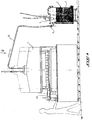
- a carriage forming a reserve of fragile solid particles 4.
- these fragile solid particles may consist of spherical balls of calcium alginate including microorganisms, for example yeasts used for the fermentation of a liquid, such as wine.
- this liquid consists of wine, in particular champagne wine.
- the solid particles 4 are suspended in a liquid 5 preferably consisting of wine. This suspension is made homogeneous by stirring carried out by means of an agitator 6.
- the carriage 2 is mounted movable on rails 8 and visible in FIG. 2 so as to be replaced by a spare carriage or wagon 2 '.
- the carriage 2 is easily disconnected connected by any known rapid connection means 9 to a conduit 10 which can be seen clearly in FIG. 4 and which brings the solid particles 4 in suspension in a tank 12 annular provided inside the device 1, and which is integral with the chassis 14 of the device, in a fixed position or rotating in solidarity with the barrel 60 described below.
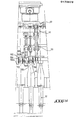
- the device according to the invention 1 is characterized in that it comprises a transfer and / or metering device 16 comprising an elongated chamber 18 comprising a wall lateral 20, preferably essentially cylindrical as shown, defining said chamber, said chamber having an open lower end 22 and a closed upper end 24 and comprising a transverse partition 26 provided with at least one orifice 28 and preferably a plurality of orifices as shown, of diameter smaller than the diameter of said solid particles 4, arranged substantially perpendicular to said side wall 20 and at a distance from the ends 22, 24 of said chamber.
- a transfer and / or metering device 16 comprising an elongated chamber 18 comprising a wall lateral 20, preferably essentially cylindrical as shown, defining said chamber, said chamber having an open lower end 22 and a closed upper end 24 and comprising a transverse partition 26 provided with at least one orifice 28 and preferably a plurality of orifices as shown, of diameter smaller than the diameter of said solid particles 4, arranged substantially perpendicular to said side
- this transverse partition 26 therefore subdivides the chamber 18 into two communicating compartments, a first transfer and / or metering compartment 18a proper ending at its lower end by an opening defined by the open lower end 22 of chamber 18, and a second compartment 18b called suction or discharge cooperating with suction or discharge means 30; and actuation means 32 of said suction or discharge means 30 (FIGS. 3 and 8).
- the suction or delivery means 30 comprise a piston 34 arranged in the second compartment 18b called suction or delivery, slidingly relative to said compartment which thus forms a cylinder body; said piston 34 being actuated by the aforementioned actuating means 32.
- the transfer and / or metering device 16 is mounted displaceable in vertical translation and in rotation relative to the chassis 14, between a position for sampling or aspiration of the solid particles 4 suspended in the tank 12, which is shown in Figure 3; a delivery position shown in FIG. 4, solid particles 4 in any container, in particular a bottle 40, which can be seen clearly in FIGS. 3 and 4.
- the actuation means 32 comprise mechanical control means.
- these mechanical control means comprise cam elements 44 and 46 cooperating with cam follower elements 50 and 52.
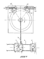
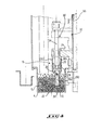
- the apparatus according to the invention 1 comprises a barrel 60 rotatably mounted relative to the chassis 14, and provided with a plurality of transfer and / or metering devices 16 spaced between them according to a predetermined step.
- Means 62, 64 for conveying receptacles 40 for receiving solid particles, in particular bottles, are also provided for conveying said receptacles opposite each transfer and / or metering device 16, as is clearly understandable from the Figures 2, 3 and 4 in particular.
- 40 devices 16 are provided to achieve a high rate, for example 25,000 bottles per hour.
- These conveying means may more precisely comprise a barrel 64 for distributing containers 40 radially external relative to the barrel 60 comprising the transfer and / or metering devices 16.
- synchronization means are well known in the art and include cogwheel systems such as the cogwheels 66, 68 visible in FIG. 3.
- the containers 40 can be brought one behind the other using the means 62 constituted according to the example represented by an endless screw, in a completely conventional manner.
- the barrel 64 driven in rotation by a shaft 70 common to the toothed wheel 68, causes the containers 40 to pass from the means 62, constituted here by a worm, over means for receiving containers 72 which are see clearly in Figures 3 and 4.
- reception means like the distribution means, are entirely conventional in the technique of filling containers, in particular bottles.
- These receiving means 72 comprise a hollow support element 74 in which is placed a piston so as to form a pneumatic cylinder by a supply from the bottom, that is to say in the channel 78 by a hydraulic fluid, in particular of the air, so that in the case of the presence of a pressure on the neck of the bottle, the support element 74 moves, in particular downwards, avoiding damaging the container, in particular when it is a glass bottle 40 or other fragile material.
- reception means 72 are guided in movement by a system of rollers 80 rolling in appropriate cam tracks 82 defined in a corresponding part of the barrel 60.
- routing means at the outlet of the apparatus according to the invention 1, which are clearly visible in FIG. 7 and which are referenced 62 ′, 64 ′.
- the rotation of the means 62 ', 64' is identical to that of the means 62, 64 but, thanks to their positioning, as clearly visible in Figures 2 and 7, the routing means 62 ', 64' result in a transfer of the containers 40 beyond the transfer and / or metering device 1 to either a container storage station 40 or to another device for introducing other elements into the containers.
- bottles 40 intended to be filled with wine it is possible to fill the bottles or containers or the like 40 with wine in a subsequent step, as is preferred according to the invention although it is possible to proceed in the opposite direction. .
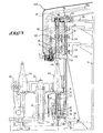
- the transfer and / or metering device 16 is mounted displaceable in vertical translation and in rotation relative to the chassis 14 between a removal position shown in FIG. 3 and a delivery position shown in FIG. 4.
- the transfer and / or metering device 16 is integral in rotation with a splined shaft 90 disposed substantially vertically and mounted in free rotation relative to the barrel 60.
- This splined shaft 90 is controlled by it - even in rotation by cam follower means 92 cooperating with cam means 94 integral with the chassis 14 of the device 1.
- the cam follower means 92 here take the form of a piston moving in a cylinder body 96 , pushed permanently by an elastic means such as a spring 98 against the cam means 94.
- the containers 40 are preferably arranged on the receiving means 72 substantially on the circumference of movement kinematics of the axis of rotation of the transfer and / or metering device 16, that is to say of the axis of rotation of the splined shaft 90, offset relative to this shaft splined 90 so that by rotation of the splined shaft 90, the transfer and / or metering device 16 is either positioned above the reservoir 12 of solid particles to be transferred is still above the containers 40 into which the solid particles are to be transferred ( Figures 3 and 4).
- the cylinder body 96 has an external rack-and-pinion shape 97 meshing with a toothed wheel 91 secured to the splined shaft 90 (FIGS. 3 and 5).
- cam means 94 have a cam profile causing this displacement to take place.
- This cam profile is represented by curve C in FIG. 6. It will be observed that in the embodiment shown, the radial dimension of the cam means 94 is simply varied to obtain rotation of the splined shaft 90 and therefore of the transfer and / or metering device 16. It is understood that according to the example shown, when the radial dimension of the cam means 94 is the largest, the positioning of the transfer and / or metering device 16 relatively 3 the shaft grooved 90 is that of FIG.
- the apparatus 1 preferably comprises a safety device 100 which is clearly visible in FIG. 5, preventing the backflow of the solid particles sucked into the first compartment of the transfer and / or metering device 16 when there is no container 40 on the receiving means 72.
- the safety device 100 comprises a means 102 forming a ring, preferably of substantially cylindrical shape, comprising a lower part adapted to the upper end of the containers 40.
- the lower part 102a of the ring 102 comprises an internal cavity 104 with a frustoconical profile, the small base of which is directed towards the inside of the ring 102.
- This ring 102 is mounted vertically movable relative to the barrel 60 so that when receiving a container 40 on the receiving means 72, the container will push up the ring, thereby causing exact positioning of the container 40 thanks to the profile 104.
- the ring 102 is provided, here at its upper part 102b with a substantially horizontal extension 106 comprising a vertical finger 108 having a function, in position bottom of the ring 102, in the absence of a container 40, stop stop of a horizontal finger 110 integral with the lower part of the splined shaft 90. It is easily understood that, in the presence of a bottle , as visible in the central position in FIG.
- the ring 102 which has been pushed upwards by the upper end of the container 40, brings up the vertical finger 108 serving as a retractable stop, by retracting it upwards and leaving free passage to the horizontal finger 110 of the splined shaft 90 which can then rotate freely when the cam follower means 92 will have to follow a variation in profile of the cam means 94.
- the ring 102 is constantly pushed down by a means usual elastic 112, such as a spring.
- the transfer and / or metering device 16 is mounted in free vertical translation relative to the splined shaft 90.
- This vertical translation movement is controlled as follows (fig. 3, 5 and 8).
- the transfer and / or metering device 16 is mounted integral with the cam follower elements 52, by a sleeve 48 coaxial with the shaft 90, cooperating with cam means 46, which are preferably made in the chassis 14 of the 'apparatus.
- the cam follower means 52 in practice comprise a roller 53 rolling on a corresponding cam track.
- the profile of the cam track 46 is represented in FIG. 6 by the curve B. It can be seen that this profile includes vertical bosses 116, 118 comprising on the one hand a rise profile 116a, 118a of the transfer device and / or of metering and a descent profile 116b, 118b of this device 16. It is understood that a vertical displacement 16 of the metering device is necessary before each transfer step between the reservoir 12 and the container 40 and, to also allow correct insertion of the end 22 of the transfer and / or metering device 16 in the reservoir 12 or in the container 40.
- the actuating means 30, comprising the piston 34, also comprise a sleeve element 120 mounted coaxially with the splined shaft 90 to be controlled in rotation by the latter, which is integral with the cam follower means 50 previously mentioned cooperating with means forming a cam 44 whose cam profile is represented by curve A in FIG. 6.
- this profile A of means forming a cam 44 comprises two bosses 122, 124, the profile of the boss 122 comprising a base flared upstream and downstream in the direction of rotation of the barrel 60.
- the part 126 of upstream boss is anterior to the boss 116 so as to allow a relative movement of the piston 34 and thus to cause aspiration of the particles solids 4 (suspended in liquid 5) appropriately, so that at point 128, the suction is complete and all the solid particles are sucked into the first compartment 18a. It is also understood that between point 128 and point 130 the curves 122a, 116a of the bosses 122, 116 cause a vertical movement upwards of the entire device. Then between point 130 and point 132, there is no vertical movement of the vertical device 16 but a rotation movement by virtue of the profile part T of the means forming cam 94 causing the rotation of the splined shaft 90.
- FIG. 7 representing the kinematic movements of the metering device 16 during the rotation of the barrel 60, the important points of the cam profile being represented in FIG. 7.
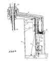
- the safety device 100 prevents the transfer of the metering device 16 above the container 40 and then the discharge of solid particles is carried out in the container 12 annular in shape.
- the device In order to properly protect the device and avoid accidental projection of any products into the reservoir 12, the device is provided with a cover 150 axially supported by a piston 152 of a hydraulic cylinder so as to obtain a vertical movement thereof. by injecting hydraulic fluid through line 154, to allow easy access to the device. It is planned, preferably according to the invention, to introduce an inert and / or sterile gas and / or filtered by a suitable conduit 156 visible in FIG. 3, inside the cover 150 so as to completely isolate the interior from the outside.
- the gas can be C02, N 2 or filtered and / or sterile air.
- means can be provided for cleaning the "active" part of the device according to the invention, that is to say the reservoir 12, and the metering device 16.
- a rinsing solution can be brought in through the usual supply conduit 10 for solid particles and by the rotation of the barrel 60, this solution will be drawn into the compartments 18a, 18b of the device 16 with then the delivery of the cleaning solution through the annular tank 12, thereby obtaining correct cleaning.
- the particles are advantageously beads spheres of calcium alginate including fermentation microorganisms, for example yeasts.
- the solid particles are preferably constituted by polymer beads of density higher or slightly higher than that of the liquid.
- the diameter of the orifices 28 of the partition 26 is naturally adapted to the size of the particles. solids 4 to filter them.
- the solid particles 4 are spherical balls of calcium alginate including fermentation microorganisms, for example yeasts, the average diameter is of the order of 1.5 to 3 mm.
- the device 26 is provided in several parts easily connectable or disconnectable with each other by any known means.
- the lower compartment 18a, incorporating the partition 26 forming a filter is formed by a part 200 and the upper compartment 186 is formed by at least one second part 202.
- the reservoir 12 is supplied at a constant level and includes any suitable corresponding known device.
- the tank 12 There is no agitation provided in the tank 12 because it is currently considered unnecessary. Indeed, even if the solid particles 4 decant in the tank 12, it suffices to insert the sampling end 22 into the decanted particles, as visible in FIG. 8, to always take the same amount of particles 4. Furthermore preferably the amount of liquid is small so that the reservoir essentially contains particles on a large level as is easily understandable to a person skilled in the art.
- the invention therefore includes all the means constituting technical equivalents of all the means described.
Landscapes
- Engineering & Computer Science (AREA)
- Chemical & Material Sciences (AREA)
- Mechanical Engineering (AREA)
- Physics & Mathematics (AREA)
- Fluid Mechanics (AREA)
- General Physics & Mathematics (AREA)
- Organic Chemistry (AREA)
- General Health & Medical Sciences (AREA)
- Zoology (AREA)
- Biochemistry (AREA)
- Bioinformatics & Cheminformatics (AREA)
- General Engineering & Computer Science (AREA)
- Health & Medical Sciences (AREA)
- Genetics & Genomics (AREA)
- Quality & Reliability (AREA)
- Wood Science & Technology (AREA)
- Life Sciences & Earth Sciences (AREA)
- Basic Packing Technique (AREA)
- Analysing Materials By The Use Of Radiation (AREA)
- Physical Or Chemical Processes And Apparatus (AREA)
- Feeding, Discharge, Calcimining, Fusing, And Gas-Generation Devices (AREA)
- Investigating Or Analyzing Materials Using Thermal Means (AREA)
- Container Filling Or Packaging Operations (AREA)
- Containers And Packaging Bodies Having A Special Means To Remove Contents (AREA)
Priority Applications (1)
| Application Number | Priority Date | Filing Date | Title |
|---|---|---|---|
| AT85401704T ATE33040T1 (de) | 1984-10-02 | 1985-09-02 | Verfahren und geraet zum uebertragen und dosieren sproeder teilchen mit hohem rhythmus z.b. zum einbringen in einen behaelter. |
Applications Claiming Priority (2)
| Application Number | Priority Date | Filing Date | Title |
|---|---|---|---|
| FR8415129 | 1984-10-02 | ||
| FR8415129A FR2571135B1 (fr) | 1984-10-02 | 1984-10-02 | Procede et appareil de transfert et/ou de dosage de particules fragiles, a cadence elevee, en vue, par exemple, de l'insertion dans un recipient |
Publications (2)
| Publication Number | Publication Date |
|---|---|
| EP0179678A1 true EP0179678A1 (de) | 1986-04-30 |
| EP0179678B1 EP0179678B1 (de) | 1988-03-16 |
Family
ID=9308278
Family Applications (1)
| Application Number | Title | Priority Date | Filing Date |
|---|---|---|---|
| EP85401704A Expired EP0179678B1 (de) | 1984-10-02 | 1985-09-02 | Verfahren und Gerät zum Übertragen und Dosieren spröder Teilchen mit hohem Rhythmus z.B. zum Einbringen in einen Behälter |
Country Status (9)
| Country | Link |
|---|---|
| US (1) | US4655265A (de) |
| EP (1) | EP0179678B1 (de) |
| AT (1) | ATE33040T1 (de) |
| AU (1) | AU569574B2 (de) |
| DE (2) | DE179678T1 (de) |
| ES (1) | ES8608573A1 (de) |
| FR (1) | FR2571135B1 (de) |
| NZ (1) | NZ213556A (de) |
| PT (1) | PT81224B (de) |
Cited By (2)
| Publication number | Priority date | Publication date | Assignee | Title |
|---|---|---|---|---|
| EP0354130A1 (de) * | 1988-08-04 | 1990-02-07 | Société dite: SCOMA S.A. | Verfahren und Vorrichtung zum Beimengen eines Stoffes zu einer Flüssigkeit, insbesondere von Ferment zu Wein |
| FR2678398A1 (fr) * | 1991-06-28 | 1992-12-31 | Champagne Moet Chandon | Procede de delivrance d'une quantite determinee de particules en suspension dans un fluide et appareil pour l'execution de ce procede. |
Families Citing this family (4)
| Publication number | Priority date | Publication date | Assignee | Title |
|---|---|---|---|---|
| US5007466A (en) * | 1989-07-19 | 1991-04-16 | Osgood Industries, Inc. | Method and apparatus for filling ice cream containers |
| DE4215325A1 (de) * | 1992-01-21 | 1993-07-22 | Gerhard Haese | Likoerdosage-rundtischfueller zur winzersekterzeugung |
| US5649576A (en) * | 1996-02-26 | 1997-07-22 | Pharmacopeia, Inc. | Partitioning device |
| CN117141833B (zh) * | 2023-11-01 | 2024-02-13 | 广州洁宜日化用品有限公司 | 一种洗衣凝珠颗粒包装提升设备及洗衣凝珠的制备工艺 |
Citations (4)
| Publication number | Priority date | Publication date | Assignee | Title |
|---|---|---|---|---|
| US2356176A (en) * | 1941-12-10 | 1944-08-22 | American Can Co | Filling machine |
| USB394742I5 (de) * | 1973-09-06 | 1976-04-13 | ||
| FR2432095A1 (fr) * | 1978-06-19 | 1980-02-22 | Maschf Augsburg Nuernberg Ag | Moteur a combustion interne, a injection directe et a compression d'air |
| DE3202655C1 (de) * | 1982-01-28 | 1983-04-07 | Sick, Peter, 7804 Glottertal | Verfahren und Vorrichtung zum Hinzugeben einer vorgegebenen Menge einer zweiten Fluessigkeit(Dosierfluessigkeit)zu einer in einem Behaelter befindlichen ersten Fluessigkeit |
Family Cites Families (2)
| Publication number | Priority date | Publication date | Assignee | Title |
|---|---|---|---|---|
| US394742A (en) * | 1888-12-18 | James webster | ||
| FR2432045A1 (fr) * | 1978-07-26 | 1980-02-22 | Agronomique Inst Nat Rech | Procede perfectionne de preparation de vins mousseux |
-
1984
- 1984-10-02 FR FR8415129A patent/FR2571135B1/fr not_active Expired
-
1985
- 1985-09-02 EP EP85401704A patent/EP0179678B1/de not_active Expired
- 1985-09-02 DE DE198585401704T patent/DE179678T1/de active Pending
- 1985-09-02 AT AT85401704T patent/ATE33040T1/de active
- 1985-09-02 DE DE8585401704T patent/DE3561891D1/de not_active Expired
- 1985-09-12 AU AU47408/85A patent/AU569574B2/en not_active Ceased
- 1985-09-13 US US06/775,733 patent/US4655265A/en not_active Expired - Fee Related
- 1985-09-19 NZ NZ213556A patent/NZ213556A/en unknown
- 1985-09-27 ES ES547358A patent/ES8608573A1/es not_active Expired
- 1985-09-30 PT PT81224A patent/PT81224B/pt not_active IP Right Cessation
Patent Citations (4)
| Publication number | Priority date | Publication date | Assignee | Title |
|---|---|---|---|---|
| US2356176A (en) * | 1941-12-10 | 1944-08-22 | American Can Co | Filling machine |
| USB394742I5 (de) * | 1973-09-06 | 1976-04-13 | ||
| FR2432095A1 (fr) * | 1978-06-19 | 1980-02-22 | Maschf Augsburg Nuernberg Ag | Moteur a combustion interne, a injection directe et a compression d'air |
| DE3202655C1 (de) * | 1982-01-28 | 1983-04-07 | Sick, Peter, 7804 Glottertal | Verfahren und Vorrichtung zum Hinzugeben einer vorgegebenen Menge einer zweiten Fluessigkeit(Dosierfluessigkeit)zu einer in einem Behaelter befindlichen ersten Fluessigkeit |
Cited By (5)
| Publication number | Priority date | Publication date | Assignee | Title |
|---|---|---|---|---|
| EP0354130A1 (de) * | 1988-08-04 | 1990-02-07 | Société dite: SCOMA S.A. | Verfahren und Vorrichtung zum Beimengen eines Stoffes zu einer Flüssigkeit, insbesondere von Ferment zu Wein |
| FR2635098A1 (fr) * | 1988-08-04 | 1990-02-09 | Scoma Sa | Procede et machine pour ajouter un produit a un liquide, notamment l'ajout de ferment dans le vin |
| FR2678398A1 (fr) * | 1991-06-28 | 1992-12-31 | Champagne Moet Chandon | Procede de delivrance d'une quantite determinee de particules en suspension dans un fluide et appareil pour l'execution de ce procede. |
| EP0526278A1 (de) * | 1991-06-28 | 1993-02-03 | CHAMPAGNE MOET & CHANDON | Prozess zur Abgabe einer vorbestimmten Menge von in Suspension eines Fluides befindlichen Partikeln und Einrichtung zur Durchführung dieses Prozesses |
| US5323930A (en) * | 1991-06-28 | 1994-06-28 | Champagne Moet & Chandon | Method of dispensing a determined amount of particles suspended in a fluid and device for carrying out this method |
Also Published As
| Publication number | Publication date |
|---|---|
| DE179678T1 (de) | 1986-09-04 |
| EP0179678B1 (de) | 1988-03-16 |
| FR2571135B1 (fr) | 1987-02-06 |
| DE3561891D1 (en) | 1988-04-21 |
| PT81224B (pt) | 1987-08-19 |
| US4655265A (en) | 1987-04-07 |
| AU569574B2 (en) | 1988-02-04 |
| ES547358A0 (es) | 1986-06-16 |
| NZ213556A (en) | 1987-06-30 |
| ATE33040T1 (de) | 1988-04-15 |
| FR2571135A1 (fr) | 1986-04-04 |
| AU4740885A (en) | 1986-04-10 |
| ES8608573A1 (es) | 1986-06-16 |
| PT81224A (fr) | 1985-10-01 |
Similar Documents
| Publication | Publication Date | Title |
|---|---|---|
| EP2821146B1 (de) | Vorrichtung und Verfahren zum Rütteln und Zentrifugieren | |
| FR2550777A1 (fr) | Dispositif pour vider des recipients contenant des produits de viscosite elevee | |
| FR2474010A1 (fr) | Soutireuse pour installation de conditionnement de recipients, notamment de bouteilles de liquides carbonates | |
| FR3007671A1 (fr) | Dispositif de secouage. | |
| EP0179678B1 (de) | Verfahren und Gerät zum Übertragen und Dosieren spröder Teilchen mit hohem Rhythmus z.B. zum Einbringen in einen Behälter | |
| EP0019539A1 (de) | Verfahren zum Schälen von hartgekochten Eiern und Maschinen zur Durchführung des Verfahrens | |
| EP0269507B1 (de) | Verfahren und Anlage zum Füllen von Behältern mit einer Mischung aus mindestens zwei pastösen oder flüssigen Produkten | |
| EP0592312B1 (de) | Dosierer, Dosierventil und Vorrichtung zum chargenweisen Dosieren von Flüssigkeit | |
| WO2021122435A1 (fr) | Bec de remplissage comprenant un canal d'aspiration | |
| EP1235715B1 (de) | Verfahren und vorrichtung zum konditionnieren einer festen substanz in einem behälter, wie einem fläschchen | |
| EP0192517B1 (de) | Dosiervorrichtung, insbesondere für Nahrungsprodukte | |
| FR2521224A1 (fr) | Procede et dispositif pour l'addition d'une quantite predeterminee d'un second liquide (liquide a doser) a un premier liquide qui se trouve dans un recipient | |
| FR2950608A1 (fr) | Dispositif de remplissage avec bec particulier | |
| EP4031479B1 (de) | Verfahren und maschine zum befüllen eines behälters mit einem gewünschten flüssigkeitsniveau | |
| FR2638432A1 (fr) | Procede et dispositif pour ameliorer la conservation de tout produit sujet a l'oxydation et/ou l'evaporation par l'air | |
| EP3532389B1 (de) | Verfahren und vorrichtungen zum befüllen von töpfen, topfverpackungslinien | |
| EP0214903A1 (de) | Automatische Probeentnahmevorrichtungen | |
| FR3053323A1 (fr) | Dispositif et procede de dosage d'un produit liquide ou pateux dans un recipient | |
| FR3098207A1 (fr) | Dispositif de fourniture d'éléments de bouchage triés | |
| WO2002024524A1 (fr) | Dispositif de remplissage de liquide a fermeture automatique | |
| EP0526278B1 (de) | Prozess zur Abgabe einer vorbestimmten Menge von in Suspension eines Fluides befindlichen Partikeln und Einrichtung zur Durchführung dieses Prozesses | |
| FR2543458A1 (fr) | Procede et installation pour nettoyer des machines de remplissage de bouteilles | |
| FR2913679A1 (fr) | Dispositif de remplissage d'un recipient par un liquide | |
| FR2628389A1 (fr) | Appareil de remplissage de recipients | |
| FR3010398A1 (fr) | Dispositif semi-automatique de remplissage et de bouchage d'une bouteille |
Legal Events
| Date | Code | Title | Description |
|---|---|---|---|
| PUAI | Public reference made under article 153(3) epc to a published international application that has entered the european phase |
Free format text: ORIGINAL CODE: 0009012 |
|
| AK | Designated contracting states |
Kind code of ref document: A1 Designated state(s): AT BE DE FR GB IT LU NL |
|
| ITCL | It: translation for ep claims filed |
Representative=s name: DE DOMINICIS & PARTNERS |
|
| 17P | Request for examination filed |
Effective date: 19860516 |
|
| DET | De: translation of patent claims | ||
| 17Q | First examination report despatched |
Effective date: 19870302 |
|
| GRAA | (expected) grant |
Free format text: ORIGINAL CODE: 0009210 |
|
| AK | Designated contracting states |
Kind code of ref document: B1 Designated state(s): AT BE DE FR GB IT LU NL |
|
| PG25 | Lapsed in a contracting state [announced via postgrant information from national office to epo] |
Ref country code: NL Effective date: 19880316 Ref country code: AT Effective date: 19880316 |
|
| REF | Corresponds to: |
Ref document number: 33040 Country of ref document: AT Date of ref document: 19880415 Kind code of ref document: T |
|
| REF | Corresponds to: |
Ref document number: 3561891 Country of ref document: DE Date of ref document: 19880421 |
|
| ITF | It: translation for a ep patent filed | ||
| NLV1 | Nl: lapsed or annulled due to failure to fulfill the requirements of art. 29p and 29m of the patents act | ||
| GBV | Gb: ep patent (uk) treated as always having been void in accordance with gb section 77(7)/1977 [no translation filed] | ||
| PG25 | Lapsed in a contracting state [announced via postgrant information from national office to epo] |
Ref country code: LU Free format text: LAPSE BECAUSE OF NON-PAYMENT OF DUE FEES Effective date: 19880930 Ref country code: BE Effective date: 19880930 |
|
| PG25 | Lapsed in a contracting state [announced via postgrant information from national office to epo] |
Ref country code: GB Free format text: LAPSE BECAUSE OF NON-PAYMENT OF DUE FEES Effective date: 19881124 |
|
| PLBE | No opposition filed within time limit |
Free format text: ORIGINAL CODE: 0009261 |
|
| STAA | Information on the status of an ep patent application or granted ep patent |
Free format text: STATUS: NO OPPOSITION FILED WITHIN TIME LIMIT |
|
| 26N | No opposition filed | ||
| BERE | Be: lapsed |
Owner name: CHAMPAGNE MOET & CHANDON Effective date: 19880930 |
|
| ITTA | It: last paid annual fee | ||
| PGFP | Annual fee paid to national office [announced via postgrant information from national office to epo] |
Ref country code: DE Payment date: 19970905 Year of fee payment: 13 |
|
| PG25 | Lapsed in a contracting state [announced via postgrant information from national office to epo] |
Ref country code: DE Free format text: LAPSE BECAUSE OF NON-PAYMENT OF DUE FEES Effective date: 19990701 |
|
| PGFP | Annual fee paid to national office [announced via postgrant information from national office to epo] |
Ref country code: FR Payment date: 20010928 Year of fee payment: 17 |
|
| PG25 | Lapsed in a contracting state [announced via postgrant information from national office to epo] |
Ref country code: FR Free format text: LAPSE BECAUSE OF NON-PAYMENT OF DUE FEES Effective date: 20030603 |
|
| REG | Reference to a national code |
Ref country code: FR Ref legal event code: ST |