EP4033058A1 - Ferrure pour limiter la largeur d'ouverture d'un vantail de fenêtre pivotant contre un cadre - Google Patents
Ferrure pour limiter la largeur d'ouverture d'un vantail de fenêtre pivotant contre un cadre Download PDFInfo
- Publication number
- EP4033058A1 EP4033058A1 EP22150852.6A EP22150852A EP4033058A1 EP 4033058 A1 EP4033058 A1 EP 4033058A1 EP 22150852 A EP22150852 A EP 22150852A EP 4033058 A1 EP4033058 A1 EP 4033058A1
- Authority
- EP
- European Patent Office
- Prior art keywords
- fitting
- latching
- slider
- stop
- recess
- Prior art date
- Legal status (The legal status is an assumption and is not a legal conclusion. Google has not performed a legal analysis and makes no representation as to the accuracy of the status listed.)
- Granted
Links
Images


Classifications
-
- E—FIXED CONSTRUCTIONS
- E05—LOCKS; KEYS; WINDOW OR DOOR FITTINGS; SAFES
- E05C—BOLTS OR FASTENING DEVICES FOR WINGS, SPECIALLY FOR DOORS OR WINDOWS
- E05C17/00—Devices for holding wings open; Devices for limiting opening of wings or for holding wings open by a movable member extending between frame and wing; Braking devices, stops or buffers, combined therewith
- E05C17/02—Devices for holding wings open; Devices for limiting opening of wings or for holding wings open by a movable member extending between frame and wing; Braking devices, stops or buffers, combined therewith by mechanical means
- E05C17/04—Devices for holding wings open; Devices for limiting opening of wings or for holding wings open by a movable member extending between frame and wing; Braking devices, stops or buffers, combined therewith by mechanical means with a movable bar or equivalent member extending between frame and wing
- E05C17/12—Devices for holding wings open; Devices for limiting opening of wings or for holding wings open by a movable member extending between frame and wing; Braking devices, stops or buffers, combined therewith by mechanical means with a movable bar or equivalent member extending between frame and wing consisting of a single rod
- E05C17/24—Devices for holding wings open; Devices for limiting opening of wings or for holding wings open by a movable member extending between frame and wing; Braking devices, stops or buffers, combined therewith by mechanical means with a movable bar or equivalent member extending between frame and wing consisting of a single rod pivoted at one end, and with the other end running along a guide member
- E05C17/28—Devices for holding wings open; Devices for limiting opening of wings or for holding wings open by a movable member extending between frame and wing; Braking devices, stops or buffers, combined therewith by mechanical means with a movable bar or equivalent member extending between frame and wing consisting of a single rod pivoted at one end, and with the other end running along a guide member with braking, clamping or securing means at the connection to the guide member
Definitions
- the invention relates to a fitting for limiting an opening width of a sash of a window, a balcony door or the like, which can be pivoted against a frame, with a sash-side fitting arrangement and a frame-side fitting arrangement, with a limiting element connecting the fitting arrangements with one another, one of the fitting arrangements having a stop and one opposite the stop Has latching means for limiting the opening width, wherein in one of the fitting arrangements a slider coupled to the limiting element is guided in a longitudinally displaceable manner and the fitting arrangement guiding the slider has the stop for limiting the range of movement.
- a fitting for limiting the opening width of a sash of a window is known from practice in various embodiments. Limiting the opening width allows ventilation through the window, but prevents further opening, for example for security reasons. However, for cleaning purposes, for example, it is often necessary to fully open the wing.
- An opening-limiting device of the type mentioned is, for example, from EP 3 034 728 A1 known.
- a displaceable adjusting body can be connected to a resilient locking bolt.
- the slider can be moved towards and away from the adjusting body held by the locking bolt.
- the opening-limiting device has a large number of components to be assembled and is complex in construction.
- An opening limit for a fitting is from the EP 2 107 194 A1 known.
- a stop for limiting the opening width is coupled with latching means that allow movement of the leaf in the closing direction and prevent it in the opening direction.
- the stop can be unlocked by actuating an unlocking means in order to move the sash beyond the stop in the opening direction.
- the movement of the wing during operation leads to a regular load on the locking means.
- the components for limiting the opening width have only a very low level of stability.
- the invention is based on the problem of developing a fitting of the type mentioned at the outset in such a way that it has a high degree of stability and is of compact design.
- this problem is solved in that the stop is arranged at the end of a latching recess and that the latching means is designed as a movable latching hook and penetrates into the latching recess.
- the slider ensures reliable guidance of the components relative to the stop.
- today's frames and wings having a rebate groove the slider can simply be guided in the rebate groove.
- the fitting has a particularly high level of stability.
- the fitting is particularly compact. Thanks to the invention, the latching hook limits the range of movement of the slider in one latching position. If the locking hook is moved out of the locking recess in the other locking position, the range of movement of the slider is released from the stop.
- an optional release or limitation of the opening width is structurally particularly simple if the fitting arrangement having the slider has a latching device and if the slider is coupled to the stop in one latching position of the latching device and from the stop is released.
- the latching hook could, for example, be connected directly to an actuator in order to control the two positions of the latching device.
- the load on the actuator during operation of the fitting can be kept particularly low if the latching hook is pretensioned in the latching recess and if a controllable actuator is designed to move the latching hook out of the latching recess. This design avoids loading the actuator when the limiting element limits the opening width during operation of the fitting.
- the actuation of the latching device is particularly simple if the actuator has an actuating element that can be moved into the range of motion of the latching hook and if the latching hook is pushed out of the range of motion of the stop in one position of the actuating element and in the other position facing the attack.
- the actuating element can be driven between the two positions in a variety of ways. For this purpose, for example, an easy-to-operate button or an electronic control element can be used. Since the limitation of the opening width is to be removed during operation, for example by cleaning staff or fitters, the actuation of the actuating element is particularly simple according to another advantageous development of the invention if the actuator has a lock cylinder connected to the actuating element.
- the opening width can be easily defined during assembly of the fitting if the latching recess is arranged on a fixing part provided for the fixed arrangement.
- the position of the fixing part on the window determines the position of the stop and thus the opening width.
- the fixing part can be screwed or clamped to the sash or the frame.
- the fitting can be adapted particularly easily to the intended opening width if the fixing part has a retaining arm with the latching recess and if the latching recess has a length limited to the opening width.
- This design makes it easy to use a holding arm with a long latching recess if a large opening width is desired. Otherwise, a holding arm with a short snap-in recess can be used to keep the opening width small.
- the slider and the fixing part have a high level of stability when the latching hook penetrates through a recess in the slider into the latching recess of the retaining arm.
- the limitation of the opening width is particularly simple when the limiting element is mounted at one end of the slider and when the fixing part faces the other end of the slider.
- the fitting can be easily adapted to different frames or sashes if the slider has a sliding shoe adapted in shape to a guide groove in the sash or frame and if the sliding shoe is detachably connected to the slider.
- gliders designed according to the various frames and sashes can be adapted and kept in stock.
- the sliding shoe which is adapted to the frame or the sash, can be easily connected to the glider.
- the sliding shoe can be made of a material with a high sliding ability, while the other components of the slider are dimensioned for high stability. The sliding shoe is preferably locked to the slider.
- the sash can be locked in the fully open position if the slider and a bearing part that can be connected to one another are connected in a locked manner via a braking and coupling device.
- the fully open position can be set easily if the braking and coupling device has a first coupling and/or braking part arranged on the slider and a second coupling and/or braking part that can be fixed in the movement range of the slider .
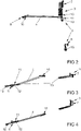
- figure 1 shows a window with a sash 2 that can be pivoted against a frame 1, with a fitting 3 for limiting the opening width of the sash 2.
- the fitting 3 has a limiting element 4 and an actuator 6 that can be controlled by a lock cylinder 5.
- FIG figure 1 a bearing part 7 of the fitting 3 is shown.
- FIG. 2 shows fitting 3 figure 1 in a fully rotationally open position.
- the fitting 3 has a fitting arrangement 8 on the frame and a fitting arrangement 9 on the sash, which are connected to one another via the delimiting element 4 .
- the frame-side fitting arrangement 8 has a bearing 10, which is fixed to the frame 1, for the delimiting element 4.
- the sash-side fitting part 9 has the bearing part 7 and a latching device 11 which has the actuator 6 that can be controlled by the lock cylinder 5.
- the sash-side fitting part 9 has a Limiting element 4 rotatably connected slider 12, which is held in the illustrated fully rotationally open position via a braking and coupling device 13 near the bearing part 7.
- figure 3 shows fitting 3 figure 1 in a limited opening width.
- the slider 12 is held here by means of the latching device 11 on a fixing part 15 attached to the wing.
- the locking device 11 prevents the movement of the slider 12 in the in figure 2 shown position and thus the movement of the in figure 1 shown wing 2 in the fully open position.
- the components of the braking and coupling device 13 are largely decoupled in this limited opening width.
- figure 4 shows the fitting 3 in the closed position, in which the in figure 1 Wing 2 shown is in the frame 1. Compared to figure 3 here the slider 12 is moved further into the fixing part 15 .
- figure 5 shows the bearing part 7 with a braking and coupling part 16 of the braking and coupling device 13 on an enlarged scale figure 2 .
- the braking and coupling part 16 can be locked in the wing 2 via a locking element 17 and is thus fixed in the movement range of the slider 12 .
- the braking and coupling part 16 In the illustrated Position is the braking and coupling part 16 fixed close to the bearing part 7 and thus allows a very large opening of the wing 2 in the fully open position.
- latching device 11 can limit the opening in the fully open position narrower.
- figure 6 shows the bearing 10 of one end of the delimiting element 4 on the frame.
- the bearing 10 has a plate 18 which can be screwed to the frame 1 and on which the limiting element 4 is rotatably mounted.
- figure 7 shows the latching device 11 with the slider 12 and adjoining areas of the delimiting element 4 in FIG figure 3 shown position in which the opening width of the fitting 3 is limited.
- one of the braking and coupling parts 14 is figure 5 described braking and coupling device 13 is arranged.
- This braking and coupling part 14 is complementary to that in figure 5 brake and coupling part 16 shown designed so that the two brake and coupling parts 14, 16 in figure 2 engage shown position of the fitting 3 and frictionally hold the wing 2 in the fully open position.
- the braking and coupling parts 14, 16 cause a braking effect on the movement of the mesh.
- One of the braking and coupling parts 14, 16, preferably the braking and coupling part 16, is designed to be elastic.
- the slider 12 is held on the fixing part 15 and has a sliding shoe 19.
- the fixing part 15 is firmly screwed to the wing 2 and has a holding arm 20 with an elongated locking recess 21.
- the actuator 6 is connected to an actuating element 22.
- figure 8 shows the latching device 11 figure 7 in an opposite and rotated view of the actuating element 22.
- FIG 9 shows a sectional view through the latching device 11 figure 8 along line IX - IX.
- the locking device 11 has a in the elongated locking recess 21 biased locking hook 23.
- a stop 24 for the locking hook 23 is arranged.
- the latching hook 23 is preloaded into the latching recess 21 by a spring element 25 .
- the actuating element 22 that can be driven by the actuator 6 penetrates into the latching recess 21 and thus into the range of movement of the latching hook 23 .
- the latching hook 23 In this position of the actuating element 22, when the wing 2 is opened, the latching hook 23 is moved over the stop 24 and the wing 2 can be moved into the fully open position. If, however, the actuating element 22 is moved into a position outside the locking recess 21, which in figure 9 is shown in phantom, the latching hook 23 remains in the position pretensioned in the latching recess 21 and, when the wing 2 is opened, reaches the limit of its opening width against the stop 24.
- the latching hook 23 has a ramp 26, so that when it moves back from the fully open position of the wing 2 is pressed into the closed position of the holding arm 20 under the stop 24 through into the recess 21.
Landscapes
- Engineering & Computer Science (AREA)
- Mechanical Engineering (AREA)
- Wing Frames And Configurations (AREA)
- Power-Operated Mechanisms For Wings (AREA)
Applications Claiming Priority (1)
| Application Number | Priority Date | Filing Date | Title |
|---|---|---|---|
| DE102021200538.1A DE102021200538A1 (de) | 2021-01-21 | 2021-01-21 | Beschlag zur Begrenzung einer Öffnungsweite eines gegen einen Rahmen schwenkbaren Flügels eines Fensters |
Publications (2)
| Publication Number | Publication Date |
|---|---|
| EP4033058A1 true EP4033058A1 (fr) | 2022-07-27 |
| EP4033058B1 EP4033058B1 (fr) | 2024-07-31 |
Family
ID=79316906
Family Applications (1)
| Application Number | Title | Priority Date | Filing Date |
|---|---|---|---|
| EP22150852.6A Active EP4033058B1 (fr) | 2021-01-21 | 2022-01-11 | Ferrure pour limiter la largeur d'ouverture d'un vantail de fenêtre pivotant contre un cadre |
Country Status (3)
| Country | Link |
|---|---|
| EP (1) | EP4033058B1 (fr) |
| DE (1) | DE102021200538A1 (fr) |
| PL (1) | PL4033058T3 (fr) |
Citations (7)
| Publication number | Priority date | Publication date | Assignee | Title |
|---|---|---|---|---|
| GB2149450A (en) * | 1983-11-10 | 1985-06-12 | Bezault Sa | Open/Closing attachment for a frame and cooperating window door or panel which is openable and closable |
| GB2246393A (en) * | 1990-07-27 | 1992-01-29 | Securistyle Ltd | A window restricting device |
| GB2260161A (en) * | 1991-09-27 | 1993-04-07 | Securistyle Ltd | A stay restricting device |
| GB2273526A (en) * | 1992-12-17 | 1994-06-22 | Euromond Ltd | Stays |
| EP2085552A1 (fr) * | 2008-01-31 | 2009-08-05 | J. Banks & Co. Ltd. | Charnière à trois barres incorporant un réducteur de fenêtre |
| EP2107194A1 (fr) | 2008-04-04 | 2009-10-07 | Schüco International KG | Limiteur d'ouverture pour une fenêtre ou une porte |
| EP3034728A1 (fr) | 2014-12-18 | 2016-06-22 | Wilh. Schlechtendahl & Söhne GmbH & Co. KG | Dispositif limiteur d'ouverture |
-
2021
- 2021-01-21 DE DE102021200538.1A patent/DE102021200538A1/de active Pending
-
2022
- 2022-01-11 EP EP22150852.6A patent/EP4033058B1/fr active Active
- 2022-01-11 PL PL22150852.6T patent/PL4033058T3/pl unknown
Patent Citations (7)
| Publication number | Priority date | Publication date | Assignee | Title |
|---|---|---|---|---|
| GB2149450A (en) * | 1983-11-10 | 1985-06-12 | Bezault Sa | Open/Closing attachment for a frame and cooperating window door or panel which is openable and closable |
| GB2246393A (en) * | 1990-07-27 | 1992-01-29 | Securistyle Ltd | A window restricting device |
| GB2260161A (en) * | 1991-09-27 | 1993-04-07 | Securistyle Ltd | A stay restricting device |
| GB2273526A (en) * | 1992-12-17 | 1994-06-22 | Euromond Ltd | Stays |
| EP2085552A1 (fr) * | 2008-01-31 | 2009-08-05 | J. Banks & Co. Ltd. | Charnière à trois barres incorporant un réducteur de fenêtre |
| EP2107194A1 (fr) | 2008-04-04 | 2009-10-07 | Schüco International KG | Limiteur d'ouverture pour une fenêtre ou une porte |
| EP3034728A1 (fr) | 2014-12-18 | 2016-06-22 | Wilh. Schlechtendahl & Söhne GmbH & Co. KG | Dispositif limiteur d'ouverture |
Also Published As
| Publication number | Publication date |
|---|---|
| PL4033058T3 (pl) | 2024-09-30 |
| DE102021200538A1 (de) | 2022-07-21 |
| EP4033058B1 (fr) | 2024-07-31 |
Similar Documents
| Publication | Publication Date | Title |
|---|---|---|
| EP2354402B1 (fr) | Verrouillage pour installations de battants | |
| DE102016202377A1 (de) | Beschlaganordnung zur Anbindung eines schieb- und kippbaren Flügels | |
| EP3835526A1 (fr) | Système de battant coulissant et tournant | |
| DE102006010755A1 (de) | Verstellvorrichtung für einen Schiebedachdeckel an einem Fahrzeug | |
| EP4033058A1 (fr) | Ferrure pour limiter la largeur d'ouverture d'un vantail de fenêtre pivotant contre un cadre | |
| DE202017105264U1 (de) | Zusatzverriegelung für eine Türanordnung | |
| EP2343429A2 (fr) | Dispositif d'appui pour un battant oscillant contre un cadre | |
| EP3708743A1 (fr) | Mécanisme à levier de réglage destiné au verrouillage ou au déverrouillage sélectif d'un battant dissimulé de fenêtres à double battant | |
| EP3371397B1 (fr) | Ensemble ferrure | |
| DE10013697A1 (de) | Feststellvorrichtung | |
| EP2772604A2 (fr) | Limiteur d'ouverture | |
| DE102021115490A1 (de) | Feststellvorrichtung für beidseitig angeschlagene Tür | |
| DE102006007672A1 (de) | Dichtungsanordnung eines Fensters, einer Tür oder dgl. | |
| EP4056797A1 (fr) | Cremone pour un vantail piovant contre un cadre | |
| EP1498563B1 (fr) | Dispositif pour créer une fente d'aération | |
| EP4628689A1 (fr) | Dispositif de limitation d'ouverture pour une crémone | |
| EP0457014A2 (fr) | Fermeture pour porte et armoire-chariot équipé d'une telle fermeture | |
| DE102021124629B4 (de) | Verschlussvorrichtung, insbesondere für einen Wohnwagen oder Wohnmobil | |
| DE202004004769U1 (de) | Beschlaganordnung | |
| EP3868984B1 (fr) | Levier de commande d'un raccord de barre de traction dissimulé dans un jeu de feuillure | |
| EP4215704B1 (fr) | Dispositif de blocage, ferrure et agencement du cadre de battant | |
| EP2196609B1 (fr) | Partie de ferrure pour une ferrure de crémone | |
| EP2090730B1 (fr) | Dispositif de verrouillage | |
| DE102023210536A1 (de) | Einrichtung zur Kopplung eines Schiebebeschlagbauteils | |
| DE102012213782A1 (de) | Verlagerungsanordnung zur Verlagerung eines Schiebeflügels eines Fensters, einer Tür oder dergleichen relativ zu einer festen Einfassung mit einem flügelseitigen und einem einfassungsseitigen Steuerelement |
Legal Events
| Date | Code | Title | Description |
|---|---|---|---|
| PUAI | Public reference made under article 153(3) epc to a published international application that has entered the european phase |
Free format text: ORIGINAL CODE: 0009012 |
|
| STAA | Information on the status of an ep patent application or granted ep patent |
Free format text: STATUS: THE APPLICATION HAS BEEN PUBLISHED |
|
| AK | Designated contracting states |
Kind code of ref document: A1 Designated state(s): AL AT BE BG CH CY CZ DE DK EE ES FI FR GB GR HR HU IE IS IT LI LT LU LV MC MK MT NL NO PL PT RO RS SE SI SK SM TR |
|
| STAA | Information on the status of an ep patent application or granted ep patent |
Free format text: STATUS: REQUEST FOR EXAMINATION WAS MADE |
|
| 17P | Request for examination filed |
Effective date: 20221215 |
|
| RBV | Designated contracting states (corrected) |
Designated state(s): AL AT BE BG CH CY CZ DE DK EE ES FI FR GB GR HR HU IE IS IT LI LT LU LV MC MK MT NL NO PL PT RO RS SE SI SK SM TR |
|
| P01 | Opt-out of the competence of the unified patent court (upc) registered |
Effective date: 20230516 |
|
| STAA | Information on the status of an ep patent application or granted ep patent |
Free format text: STATUS: EXAMINATION IS IN PROGRESS |
|
| 17Q | First examination report despatched |
Effective date: 20231031 |
|
| GRAP | Despatch of communication of intention to grant a patent |
Free format text: ORIGINAL CODE: EPIDOSNIGR1 |
|
| STAA | Information on the status of an ep patent application or granted ep patent |
Free format text: STATUS: GRANT OF PATENT IS INTENDED |
|
| INTG | Intention to grant announced |
Effective date: 20240321 |
|
| GRAS | Grant fee paid |
Free format text: ORIGINAL CODE: EPIDOSNIGR3 |
|
| GRAA | (expected) grant |
Free format text: ORIGINAL CODE: 0009210 |
|
| STAA | Information on the status of an ep patent application or granted ep patent |
Free format text: STATUS: THE PATENT HAS BEEN GRANTED |
|
| AK | Designated contracting states |
Kind code of ref document: B1 Designated state(s): AL AT BE BG CH CY CZ DE DK EE ES FI FR GB GR HR HU IE IS IT LI LT LU LV MC MK MT NL NO PL PT RO RS SE SI SK SM TR |
|
| REG | Reference to a national code |
Ref country code: CH Ref legal event code: EP Ref country code: GB Ref legal event code: FG4D Free format text: NOT ENGLISH |
|
| REG | Reference to a national code |
Ref country code: DE Ref legal event code: R096 Ref document number: 502022001324 Country of ref document: DE |
|
| REG | Reference to a national code |
Ref country code: IE Ref legal event code: FG4D Free format text: LANGUAGE OF EP DOCUMENT: GERMAN |
|
| REG | Reference to a national code |
Ref country code: DE Ref legal event code: R081 Ref document number: 502022001324 Country of ref document: DE Owner name: AUG. WINKHAUS SE & CO. KG, DE Free format text: FORMER OWNER: AUG. WINKHAUS GMBH & CO. KG, 48291 TELGTE, DE Ref country code: DE Ref legal event code: R081 Ref document number: 502022001324 Country of ref document: DE Owner name: AUG. WINKHAUS SE, DE Free format text: FORMER OWNER: AUG. WINKHAUS GMBH & CO. KG, 48291 TELGTE, DE |
|
| REG | Reference to a national code |
Ref country code: LT Ref legal event code: MG9D |
|
| RAP4 | Party data changed (patent owner data changed or rights of a patent transferred) |
Owner name: AUG. WINKHAUS SE & CO. KG |
|
| REG | Reference to a national code |
Ref country code: NL Ref legal event code: MP Effective date: 20240731 |
|
| PG25 | Lapsed in a contracting state [announced via postgrant information from national office to epo] |
Ref country code: PT Free format text: LAPSE BECAUSE OF FAILURE TO SUBMIT A TRANSLATION OF THE DESCRIPTION OR TO PAY THE FEE WITHIN THE PRESCRIBED TIME-LIMIT Effective date: 20241202 |
|
| PG25 | Lapsed in a contracting state [announced via postgrant information from national office to epo] |
Ref country code: PT Free format text: LAPSE BECAUSE OF FAILURE TO SUBMIT A TRANSLATION OF THE DESCRIPTION OR TO PAY THE FEE WITHIN THE PRESCRIBED TIME-LIMIT Effective date: 20241202 |
|
| PG25 | Lapsed in a contracting state [announced via postgrant information from national office to epo] |
Ref country code: NO Free format text: LAPSE BECAUSE OF FAILURE TO SUBMIT A TRANSLATION OF THE DESCRIPTION OR TO PAY THE FEE WITHIN THE PRESCRIBED TIME-LIMIT Effective date: 20241031 |
|
| PG25 | Lapsed in a contracting state [announced via postgrant information from national office to epo] |
Ref country code: NL Free format text: LAPSE BECAUSE OF FAILURE TO SUBMIT A TRANSLATION OF THE DESCRIPTION OR TO PAY THE FEE WITHIN THE PRESCRIBED TIME-LIMIT Effective date: 20240731 Ref country code: FI Free format text: LAPSE BECAUSE OF FAILURE TO SUBMIT A TRANSLATION OF THE DESCRIPTION OR TO PAY THE FEE WITHIN THE PRESCRIBED TIME-LIMIT Effective date: 20240731 Ref country code: GR Free format text: LAPSE BECAUSE OF FAILURE TO SUBMIT A TRANSLATION OF THE DESCRIPTION OR TO PAY THE FEE WITHIN THE PRESCRIBED TIME-LIMIT Effective date: 20241101 |
|
| PG25 | Lapsed in a contracting state [announced via postgrant information from national office to epo] |
Ref country code: BG Free format text: LAPSE BECAUSE OF FAILURE TO SUBMIT A TRANSLATION OF THE DESCRIPTION OR TO PAY THE FEE WITHIN THE PRESCRIBED TIME-LIMIT Effective date: 20240731 |
|
| PG25 | Lapsed in a contracting state [announced via postgrant information from national office to epo] |
Ref country code: LV Free format text: LAPSE BECAUSE OF FAILURE TO SUBMIT A TRANSLATION OF THE DESCRIPTION OR TO PAY THE FEE WITHIN THE PRESCRIBED TIME-LIMIT Effective date: 20240731 |
|
| PG25 | Lapsed in a contracting state [announced via postgrant information from national office to epo] |
Ref country code: IS Free format text: LAPSE BECAUSE OF FAILURE TO SUBMIT A TRANSLATION OF THE DESCRIPTION OR TO PAY THE FEE WITHIN THE PRESCRIBED TIME-LIMIT Effective date: 20241130 |
|
| PG25 | Lapsed in a contracting state [announced via postgrant information from national office to epo] |
Ref country code: HR Free format text: LAPSE BECAUSE OF FAILURE TO SUBMIT A TRANSLATION OF THE DESCRIPTION OR TO PAY THE FEE WITHIN THE PRESCRIBED TIME-LIMIT Effective date: 20240731 |
|
| PG25 | Lapsed in a contracting state [announced via postgrant information from national office to epo] |
Ref country code: RS Free format text: LAPSE BECAUSE OF FAILURE TO SUBMIT A TRANSLATION OF THE DESCRIPTION OR TO PAY THE FEE WITHIN THE PRESCRIBED TIME-LIMIT Effective date: 20241031 Ref country code: ES Free format text: LAPSE BECAUSE OF FAILURE TO SUBMIT A TRANSLATION OF THE DESCRIPTION OR TO PAY THE FEE WITHIN THE PRESCRIBED TIME-LIMIT Effective date: 20240731 |
|
| PG25 | Lapsed in a contracting state [announced via postgrant information from national office to epo] |
Ref country code: RS Free format text: LAPSE BECAUSE OF FAILURE TO SUBMIT A TRANSLATION OF THE DESCRIPTION OR TO PAY THE FEE WITHIN THE PRESCRIBED TIME-LIMIT Effective date: 20241031 Ref country code: NO Free format text: LAPSE BECAUSE OF FAILURE TO SUBMIT A TRANSLATION OF THE DESCRIPTION OR TO PAY THE FEE WITHIN THE PRESCRIBED TIME-LIMIT Effective date: 20241031 Ref country code: NL Free format text: LAPSE BECAUSE OF FAILURE TO SUBMIT A TRANSLATION OF THE DESCRIPTION OR TO PAY THE FEE WITHIN THE PRESCRIBED TIME-LIMIT Effective date: 20240731 Ref country code: LV Free format text: LAPSE BECAUSE OF FAILURE TO SUBMIT A TRANSLATION OF THE DESCRIPTION OR TO PAY THE FEE WITHIN THE PRESCRIBED TIME-LIMIT Effective date: 20240731 Ref country code: IS Free format text: LAPSE BECAUSE OF FAILURE TO SUBMIT A TRANSLATION OF THE DESCRIPTION OR TO PAY THE FEE WITHIN THE PRESCRIBED TIME-LIMIT Effective date: 20241130 Ref country code: HR Free format text: LAPSE BECAUSE OF FAILURE TO SUBMIT A TRANSLATION OF THE DESCRIPTION OR TO PAY THE FEE WITHIN THE PRESCRIBED TIME-LIMIT Effective date: 20240731 Ref country code: GR Free format text: LAPSE BECAUSE OF FAILURE TO SUBMIT A TRANSLATION OF THE DESCRIPTION OR TO PAY THE FEE WITHIN THE PRESCRIBED TIME-LIMIT Effective date: 20241101 Ref country code: FI Free format text: LAPSE BECAUSE OF FAILURE TO SUBMIT A TRANSLATION OF THE DESCRIPTION OR TO PAY THE FEE WITHIN THE PRESCRIBED TIME-LIMIT Effective date: 20240731 Ref country code: ES Free format text: LAPSE BECAUSE OF FAILURE TO SUBMIT A TRANSLATION OF THE DESCRIPTION OR TO PAY THE FEE WITHIN THE PRESCRIBED TIME-LIMIT Effective date: 20240731 Ref country code: BG Free format text: LAPSE BECAUSE OF FAILURE TO SUBMIT A TRANSLATION OF THE DESCRIPTION OR TO PAY THE FEE WITHIN THE PRESCRIBED TIME-LIMIT Effective date: 20240731 |
|
| PG25 | Lapsed in a contracting state [announced via postgrant information from national office to epo] |
Ref country code: SM Free format text: LAPSE BECAUSE OF FAILURE TO SUBMIT A TRANSLATION OF THE DESCRIPTION OR TO PAY THE FEE WITHIN THE PRESCRIBED TIME-LIMIT Effective date: 20240731 Ref country code: RO Free format text: LAPSE BECAUSE OF FAILURE TO SUBMIT A TRANSLATION OF THE DESCRIPTION OR TO PAY THE FEE WITHIN THE PRESCRIBED TIME-LIMIT Effective date: 20240731 Ref country code: DK Free format text: LAPSE BECAUSE OF FAILURE TO SUBMIT A TRANSLATION OF THE DESCRIPTION OR TO PAY THE FEE WITHIN THE PRESCRIBED TIME-LIMIT Effective date: 20240731 |
|
| PG25 | Lapsed in a contracting state [announced via postgrant information from national office to epo] |
Ref country code: EE Free format text: LAPSE BECAUSE OF FAILURE TO SUBMIT A TRANSLATION OF THE DESCRIPTION OR TO PAY THE FEE WITHIN THE PRESCRIBED TIME-LIMIT Effective date: 20240731 |
|
| PG25 | Lapsed in a contracting state [announced via postgrant information from national office to epo] |
Ref country code: CZ Free format text: LAPSE BECAUSE OF FAILURE TO SUBMIT A TRANSLATION OF THE DESCRIPTION OR TO PAY THE FEE WITHIN THE PRESCRIBED TIME-LIMIT Effective date: 20240731 |
|
| PGFP | Annual fee paid to national office [announced via postgrant information from national office to epo] |
Ref country code: PL Payment date: 20250108 Year of fee payment: 4 |
|
| PG25 | Lapsed in a contracting state [announced via postgrant information from national office to epo] |
Ref country code: SK Free format text: LAPSE BECAUSE OF FAILURE TO SUBMIT A TRANSLATION OF THE DESCRIPTION OR TO PAY THE FEE WITHIN THE PRESCRIBED TIME-LIMIT Effective date: 20240731 Ref country code: IT Free format text: LAPSE BECAUSE OF FAILURE TO SUBMIT A TRANSLATION OF THE DESCRIPTION OR TO PAY THE FEE WITHIN THE PRESCRIBED TIME-LIMIT Effective date: 20240731 |
|
| REG | Reference to a national code |
Ref country code: DE Ref legal event code: R097 Ref document number: 502022001324 Country of ref document: DE |
|
| PLBE | No opposition filed within time limit |
Free format text: ORIGINAL CODE: 0009261 |
|
| STAA | Information on the status of an ep patent application or granted ep patent |
Free format text: STATUS: NO OPPOSITION FILED WITHIN TIME LIMIT |
|
| 26N | No opposition filed |
Effective date: 20250501 |
|
| REG | Reference to a national code |
Ref country code: CH Ref legal event code: PL |
|
| REG | Reference to a national code |
Ref country code: DE Ref legal event code: R081 Ref document number: 502022001324 Country of ref document: DE Owner name: AUG. WINKHAUS SE, DE Free format text: FORMER OWNER: AUG. WINKHAUS SE & CO. KG, 48291 TELGTE, DE |
|
| PG25 | Lapsed in a contracting state [announced via postgrant information from national office to epo] |
Ref country code: SE Free format text: LAPSE BECAUSE OF FAILURE TO SUBMIT A TRANSLATION OF THE DESCRIPTION OR TO PAY THE FEE WITHIN THE PRESCRIBED TIME-LIMIT Effective date: 20240731 |
|
| PG25 | Lapsed in a contracting state [announced via postgrant information from national office to epo] |
Ref country code: MC Free format text: LAPSE BECAUSE OF FAILURE TO SUBMIT A TRANSLATION OF THE DESCRIPTION OR TO PAY THE FEE WITHIN THE PRESCRIBED TIME-LIMIT Effective date: 20240731 Ref country code: LU Free format text: LAPSE BECAUSE OF NON-PAYMENT OF DUE FEES Effective date: 20250111 |
|
| PG25 | Lapsed in a contracting state [announced via postgrant information from national office to epo] |
Ref country code: FR Free format text: LAPSE BECAUSE OF NON-PAYMENT OF DUE FEES Effective date: 20250131 |
|
| PG25 | Lapsed in a contracting state [announced via postgrant information from national office to epo] |
Ref country code: CH Free format text: LAPSE BECAUSE OF NON-PAYMENT OF DUE FEES Effective date: 20250131 |
|
| PG25 | Lapsed in a contracting state [announced via postgrant information from national office to epo] |
Ref country code: IE Free format text: LAPSE BECAUSE OF NON-PAYMENT OF DUE FEES Effective date: 20250111 |
|
| PGFP | Annual fee paid to national office [announced via postgrant information from national office to epo] |
Ref country code: GB Payment date: 20260122 Year of fee payment: 5 |
|
| PGFP | Annual fee paid to national office [announced via postgrant information from national office to epo] |
Ref country code: DE Payment date: 20260120 Year of fee payment: 5 |
|
| PGFP | Annual fee paid to national office [announced via postgrant information from national office to epo] |
Ref country code: AT Payment date: 20260301 Year of fee payment: 5 |
|
| PGFP | Annual fee paid to national office [announced via postgrant information from national office to epo] |
Ref country code: BE Payment date: 20260121 Year of fee payment: 5 |