EP4034482B1 - Procédé de configuration par ordinateur d'une application d'entraînement régulée d'un système logistique - Google Patents
Procédé de configuration par ordinateur d'une application d'entraînement régulée d'un système logistique Download PDFInfo
- Publication number
- EP4034482B1 EP4034482B1 EP20804463.6A EP20804463A EP4034482B1 EP 4034482 B1 EP4034482 B1 EP 4034482B1 EP 20804463 A EP20804463 A EP 20804463A EP 4034482 B1 EP4034482 B1 EP 4034482B1
- Authority
- EP
- European Patent Office
- Prior art keywords
- logistics system
- conveyor
- piece goods
- combining unit
- system model
- Prior art date
- Legal status (The legal status is an assumption and is not a legal conclusion. Google has not performed a legal analysis and makes no representation as to the accuracy of the status listed.)
- Active
Links
Images

Classifications
-
- G—PHYSICS
- G05—CONTROLLING; REGULATING
- G05B—CONTROL OR REGULATING SYSTEMS IN GENERAL; FUNCTIONAL ELEMENTS OF SUCH SYSTEMS; MONITORING OR TESTING ARRANGEMENTS FOR SUCH SYSTEMS OR ELEMENTS
- G05B19/00—Program-control systems
- G05B19/02—Program-control systems electric
- G05B19/418—Total factory control, i.e. centrally controlling a plurality of machines, e.g. direct or distributed numerical control [DNC], flexible manufacturing systems [FMS], integrated manufacturing systems [IMS] or computer integrated manufacturing [CIM]
- G05B19/41815—Total factory control, i.e. centrally controlling a plurality of machines, e.g. direct or distributed numerical control [DNC], flexible manufacturing systems [FMS], integrated manufacturing systems [IMS] or computer integrated manufacturing [CIM] characterised by the cooperation between machine tools, manipulators and conveyor or other workpiece supply system, workcell
- G05B19/4182—Total factory control, i.e. centrally controlling a plurality of machines, e.g. direct or distributed numerical control [DNC], flexible manufacturing systems [FMS], integrated manufacturing systems [IMS] or computer integrated manufacturing [CIM] characterised by the cooperation between machine tools, manipulators and conveyor or other workpiece supply system, workcell manipulators and conveyor only
-
- G—PHYSICS
- G05—CONTROLLING; REGULATING
- G05B—CONTROL OR REGULATING SYSTEMS IN GENERAL; FUNCTIONAL ELEMENTS OF SUCH SYSTEMS; MONITORING OR TESTING ARRANGEMENTS FOR SUCH SYSTEMS OR ELEMENTS
- G05B13/00—Adaptive control systems, i.e. systems automatically adjusting themselves to have a performance which is optimum according to some preassigned criterion
- G05B13/02—Adaptive control systems, i.e. systems automatically adjusting themselves to have a performance which is optimum according to some preassigned criterion electric
- G05B13/0265—Adaptive control systems, i.e. systems automatically adjusting themselves to have a performance which is optimum according to some preassigned criterion electric the criterion being a learning criterion
- G05B13/027—Adaptive control systems, i.e. systems automatically adjusting themselves to have a performance which is optimum according to some preassigned criterion electric the criterion being a learning criterion using neural networks only
-
- G—PHYSICS
- G05—CONTROLLING; REGULATING
- G05B—CONTROL OR REGULATING SYSTEMS IN GENERAL; FUNCTIONAL ELEMENTS OF SUCH SYSTEMS; MONITORING OR TESTING ARRANGEMENTS FOR SUCH SYSTEMS OR ELEMENTS
- G05B19/00—Program-control systems
- G05B19/02—Program-control systems electric
- G05B19/04—Program control other than numerical control, i.e. in sequence controllers or logic controllers
- G05B19/042—Program control other than numerical control, i.e. in sequence controllers or logic controllers using digital processors
- G05B19/0426—Programming the control sequence
-
- G—PHYSICS
- G05—CONTROLLING; REGULATING
- G05B—CONTROL OR REGULATING SYSTEMS IN GENERAL; FUNCTIONAL ELEMENTS OF SUCH SYSTEMS; MONITORING OR TESTING ARRANGEMENTS FOR SUCH SYSTEMS OR ELEMENTS
- G05B19/00—Program-control systems
- G05B19/02—Program-control systems electric
- G05B19/418—Total factory control, i.e. centrally controlling a plurality of machines, e.g. direct or distributed numerical control [DNC], flexible manufacturing systems [FMS], integrated manufacturing systems [IMS] or computer integrated manufacturing [CIM]
- G05B19/41885—Total factory control, i.e. centrally controlling a plurality of machines, e.g. direct or distributed numerical control [DNC], flexible manufacturing systems [FMS], integrated manufacturing systems [IMS] or computer integrated manufacturing [CIM] characterised by modeling, simulation of the manufacturing system
-
- G—PHYSICS
- G05—CONTROLLING; REGULATING
- G05B—CONTROL OR REGULATING SYSTEMS IN GENERAL; FUNCTIONAL ELEMENTS OF SUCH SYSTEMS; MONITORING OR TESTING ARRANGEMENTS FOR SUCH SYSTEMS OR ELEMENTS
- G05B19/00—Program-control systems
- G05B19/02—Program-control systems electric
- G05B19/418—Total factory control, i.e. centrally controlling a plurality of machines, e.g. direct or distributed numerical control [DNC], flexible manufacturing systems [FMS], integrated manufacturing systems [IMS] or computer integrated manufacturing [CIM]
- G05B19/4189—Total factory control, i.e. centrally controlling a plurality of machines, e.g. direct or distributed numerical control [DNC], flexible manufacturing systems [FMS], integrated manufacturing systems [IMS] or computer integrated manufacturing [CIM] characterised by the transport system
-
- G—PHYSICS
- G05—CONTROLLING; REGULATING
- G05B—CONTROL OR REGULATING SYSTEMS IN GENERAL; FUNCTIONAL ELEMENTS OF SUCH SYSTEMS; MONITORING OR TESTING ARRANGEMENTS FOR SUCH SYSTEMS OR ELEMENTS
- G05B2219/00—Program-control systems
- G05B2219/20—Pc systems
- G05B2219/26—Pc applications
- G05B2219/2621—Conveyor, transfert line
-
- G—PHYSICS
- G05—CONTROLLING; REGULATING
- G05B—CONTROL OR REGULATING SYSTEMS IN GENERAL; FUNCTIONAL ELEMENTS OF SUCH SYSTEMS; MONITORING OR TESTING ARRANGEMENTS FOR SUCH SYSTEMS OR ELEMENTS
- G05B2219/00—Program-control systems
- G05B2219/30—Nc systems
- G05B2219/32—Operator till task planning
- G05B2219/32357—Simulation of material handling, flexible conveyor system fcs
-
- G—PHYSICS
- G05—CONTROLLING; REGULATING
- G05B—CONTROL OR REGULATING SYSTEMS IN GENERAL; FUNCTIONAL ELEMENTS OF SUCH SYSTEMS; MONITORING OR TESTING ARRANGEMENTS FOR SUCH SYSTEMS OR ELEMENTS
- G05B2219/00—Program-control systems
- G05B2219/30—Nc systems
- G05B2219/33—Director till display
- G05B2219/33056—Reinforcement learning, agent acts, receives reward, emotion, action selective
Definitions
- the present invention relates to a method and a device for the computer-implemented configuration of a controlled drive application of a logistics system.
- a so-called "dynamic gapper” is a controlled drive application that is used in intralogistics.
- packages that are usually conveyed by two or more parallel conveyor lines in one direction are to be brought together on a single output conveyor line.
- the packages that are located at undefined intervals on the two or more parallel conveyor lines are to be sorted onto the output conveyor line using a combining unit and at the same time brought to defined intervals.
- the packages are combined and defined distances are created using several conveyor belts on each conveyor line.
- the conveyor belts are driven by geared motors and controlled by a frequency converter.
- the target values for the speeds of each conveyor line are specified by a controller.
- the positions of the packages on the conveyor lines are detected by sensors and processed in the controller.
- the position between the packages is usually influenced by PI controllers that operate between two packages. Based on the information available, the conveyor lines are accelerated and decelerated differently by the controller.
- control system Due to the large number of parallel conveyor lines and several conveyor belt sections that have to be accelerated and decelerated independently of each other, the control system is complex. The optimization due to various Package sizes and properties are complex. The adjustment of the control process for different mechanical structures is extensive. If, for example, the number of conveyor sections or the length of the individual conveyor sections is changed, this has a significant impact on the control process and requires adjustments to the control system.
- a fundamental overarching goal of the application is to be able to optimize the throughput of such a controlled drive application dynamically during the running process, while at the same time avoiding malfunctions of the controlled drive application, e.g. due to collisions of individual packages.
- the invention proposes a method for the computer-implemented configuration of a controlled drive application of a logistics system.
- the logistics system comprises one or more parallel conveyor lines for piece goods.
- Piece goods are in particular packages which are to be fed to a sorting system, for example.
- the present method is also suitable for all other types of piece goods.
- the conveyor lines each lead into a unitizing unit in one conveying direction.
- Each of the conveyor lines consists of a plurality of partial conveyor lines which are arranged one behind the other so that piece goods can be transported without interruption. from one partial conveyor section to another, adjacent partial conveyor section.
- the partial conveyor sections are accelerated or decelerated by a respective assigned drive under the control of a computing unit. The acceleration or deceleration takes place individually for each partial conveyor section.
- the acceleration or deceleration can also include an acceleration or deceleration value of 0.
- the combining unit arranged at the end of the conveyor sections is enabled to combine the piece goods on a single output conveyor section with a defined distance. In other words, the piece goods are brought to the output conveyor section at defined distances from one another.
- a system model of the logistics system is determined based on operational data of the logistics system, whereby the operational data is available for a large number of points in time during the operation of the logistics system and includes measured values from sensors of the logistics system and changes in control variables for each point in time.
- the system model represents a simulation model that reflects the dynamics of the logistics system.
- a control function of the logistics system is determined, whereby the control function comprises at least configuration data for the drives.
- the control function is determined using the system model by executing at least one control in the system model, specifying one or more performance characteristics to be achieved, in which the operating data is simulated for a large number of time steps.
- a reward measure is determined for each time step, whereby the control is used as a control function in which a predetermined fitness function, which the reward measures of a large number of time steps aggregated, a predetermined criterion is met, and in particular is maximized.
- the method of the invention represents a simple method for the computer-implemented determination of configuration data for the drives assigned to the partial conveyor lines.
- Configuration data within the meaning of the invention are in particular control signals for the drives in order to accelerate or decelerate the assigned partial conveyor lines in a suitable manner in order to enable the combining unit to combine the piece goods fed via the several parallel conveyor lines onto a single output conveyor line with a defined distance.
- the system model is determined using methods of supervised learning.
- the use of a neural network or a recurrent neural network is particularly preferred.
- the control function is determined in particular using reinforcement learning.
- a practical design of the method provides for the sum of the performance characteristic(s) over the simulated time steps to be processed as a fitness function.
- the sum of a specific performance characteristic over time can be used as a fitness function, e.g. an average throughput of piece goods at the output of the combining unit.
- One or more of the following parameters can be processed as a performance characteristic: an average throughput of piece goods at the output of the combining unit; a distance, in particular a minimum distance, between two piece goods conveyed directly one after the other (the distance between two piece goods conveyed directly one after the other is also referred to as the gap distance); the detection of a collision in the combining unit, in particular at its output; a distance uniformity measure that characterizes a deviation of the distances from an equidistance between two piece goods conveyed directly one after the other; a running speed of the partial conveyor sections of a respective conveyor section or of the conveyor sections as a whole.
- the control can be carried out in the system model by specifying one or more performance characteristics to be achieved.
- the input variables that are varied to determine the control function of the system model preferably simultaneously represent the operating parameters of the system model.
- the parameters mentioned are thus available to determine the system model as operating data for a large number of points in time during the operation of the logistics system and include measured values from sensors of the logistics system as well as changes in the control variables, such as a change in the respective speed of the partial conveyor lines.
- the invention relates to a device for the computer-implemented configuration of a controlled drive application of a logistics system, wherein the device comprises a computing unit for controlling a drive assigned to each partial conveyor section for acceleration or deceleration, wherein the computing unit is designed to carry out the method according to one or more preferred embodiments of the invention.
- the invention relates to a computer program with program code stored on a non-volatile, machine-readable carrier for carrying out a method according to one or more preferred embodiments the invention when the program code is executed on a computer.
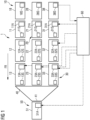
- Fig. 1 shows a schematic representation of a logistics system 1 with a controlled drive application.
- the logistics system 1 comprises, for example, three conveyor lines 10, 20, 30 running parallel to one another, on each of which piece goods, in particular packages, can be conveyed in a conveying direction FR running from right to left.
- Each of the conveyor lines 10, 20, 30 of equal length, also referred to as fingers, comprises a plurality of partial conveyor lines 11-13, 21-23, 31-33.
- the number of partial conveyor lines per conveyor line 10, 20, 30 is the same in the present embodiment, although this is not mandatory.
- the partial conveyor lines 11-13, 21-23, 31-33 of a respective conveyor line 10, 20, 30 can be the same length or have different lengths.
- a combining unit 40 is arranged, to which the last partial conveyor sections 13, 23, 33 in the conveying direction FR transfer the piece goods transported by them.
- a single output conveyor section 50 is arranged at an output 41 of the combining unit 40. This can consist of one or more partial conveyor sections 51.
- the partial conveyor section or sections 51 are in turn driven by a drive 51A under the control of the computing unit 60.
- a respective partial conveyor section 11-13, 21-23, 31-33 is provided with a number of respective sensors 11S-13S, 21S-23S, 31S-33S.
- the sensors 11S-13S, 21S-23S, 31S-33S in particular comprise light barriers for determining a respective transport speed of a piece of goods, a length of the piece of goods, a position and/or a deviation from an expected position.
- the sensors optionally include, for example, speed sensors for detecting the speed of the drives 11A-13A, 21A-23A, 31A-33A, current sensors for detecting the motor currents of the drives 11A-13A, 21A-23A, 31A-33A, etc.
- the supply of the piece goods to the conveyor lines 10, 20, 30 takes place via respective transfer units 18, 28, 38, which are also designed as partial conveyor lines, for example.
- the transfer units 18, 28, 38 also have a corresponding drive (not explicitly shown here, however) and a number of corresponding sensors 18S, 28S, 38S.
- the transfer units can be segments independent of the actual conveyor sections 10, 20, 30.
- the transfer units 18, 28, 38 can, however, also represent a respective partial conveyor section of the associated conveyor section 10, 20, 30.
- Fig. 1 only the transfer units 18, 28, 38 are provided with corresponding sensors 18S, 28S, 38S. Corresponding measurement signals are fed to the computing unit 60 for further processing. A measurement signal is shown by a dotted line. For the sake of simplicity, not all measurement signals or signal lines required for transmission are shown.
- the drives 11A-13A, 21A-23A, 31A-33A, 51A assigned to the partial conveyor sections 11-13, 21-23, 31-33 are controlled via dashed lines with corresponding control signals. For the sake of simplicity, not all control signals or control lines required for transmission are shown.
- the method described below for the computer-implemented configuration of the controlled drive application of the logistics system 1 is carried out by the computing unit 60. However, the steps can also be carried out on a computing unit that is independent of the ultimate control of the logistics system 1. The procedure is shown schematically in Fig. 2 shown.
- a system model of the logistics system 1 is determined using operational data BD of the logistics system.
- the operational data BD are available for a large number of times during the operation of the logistics system 1 and include measured values from the sensors 11S-13S, 21S-23S, 31S-33S, 18S-38S for each time, such as light barrier signals, motor currents, positions of the piece goods on the respective Partial conveyor lines 11-13, 21-23, 31-33, 18-38, speeds of the drives 11A-13A, 21A-23A, 31A-33A, and speeds of the partial conveyor lines 11-13, 21-23, 31-33.
- step S1 changes in the manipulated variables, which include, for example, changes in speed or rpm of the drives 11A-13A, 21A-23A, 31A-33A, 18A-38A, are determined and processed for each point in time.
- the system model is determined using supervised learning methods, in particular a neural network or a recurrent neural network. Since the procedure is well known, a detailed description is not provided here.
- a control function of the logistics system 1 is determined.
- the control function REGF comprises at least configuration data KD for the drives 11A-13A, 21A-23A, 31A-33A, i.e. motor currents and/or speeds and the like, so that the associated partial conveyor sections 11-13, 21-23, 31-33 can be accelerated or decelerated in a suitable manner.
- the control function REGF is determined using the system model determined in step S1, by executing at least one control in the system model, specifying one or more performance characteristics to be achieved.
- One or more of the following parameters can be processed as a performance characteristic, for example: an average throughput of piece goods at the output 41 of the combining unit 40; a distance, in particular a minimum distance, between two piece goods conveyed directly one after the other, ie a gap distance; the detection of a collision in the combining unit 40, in particular at its output 41; a distance uniformity measure, which characterizes a deviation of the distances from an equidistance between two items of goods conveyed directly one after the other, i.e. a uniformity of the gap spacing; as well as a running speed of the three conveyor sections of a respective conveyor section or of the conveyor sections as a whole, in order to achieve, for example, wear optimization.
- the operating data BD are simulated for a large number of time steps.
- a reward measure is determined for each time step.
- the control function REGF is used in which a given fitness function, which aggregates the reward measures of a large number of time steps, meets a given criterion. In particular, the aim is to maximize the reward measures.
- the control function REGF is determined using methods that are suitable for creating a control that increases the fitness function.
- the fitness function can be, for example, the sum of the performance characteristic(s) over the time steps, e.g. the average throughput. Such an approach can be achieved using reinforcement learning methods, where the fitness function is then processed as the discounted sum of the expected rewards. This can be, for example, the throughput or the proximity to a desired gap distance.
- Other goals can be a small width of the distribution of the package distances (gap distances) or a high running speed of the partial conveyor lines while maintaining certain distance quantiles of the piece goods. Since the individual goals sometimes contradict each other, these must be balanced out by the learned actions of the control function REGF.
- an optimal control function REGF for the given fitness function can be learned through reinforcement learning based on interactions with the system model. This results in an optimization of the control function REGF by training against the system model of the logistics system 1. From this, the interpretable control function REGF can then be derived, which enables the generation of the configuration data for the drives 11A-13A, 21A-23A, 31A-33A.
- control function REGF can be executed in the simulation of the system model and a large number of time steps can be simulated.
- typical model input variables such as the size of the piece goods, their mass, friction coefficients and the like, practical distributions can be generated using existing operating data BD. This enables a high level of robustness of the derived control function REGF and configuration data KD. Since the fitness function is simulated for each time step, the development of the reward measures can be approximately calculated.
- controls for changed optimization goals can be created in the short term.
- multi-step optimization similar to the well-known model predictive control, adaptation to changed optimization goals can be achieved without delay.
- operating data from other logistics systems can be used to learn a control function REGF using Q-function-based reinforcement learning methods.
- the system model can be trained with validity for all logistics systems, which then enables optimization for the logistics system under consideration.
Landscapes
- Engineering & Computer Science (AREA)
- General Physics & Mathematics (AREA)
- Automation & Control Theory (AREA)
- Physics & Mathematics (AREA)
- Manufacturing & Machinery (AREA)
- Quality & Reliability (AREA)
- General Engineering & Computer Science (AREA)
- Artificial Intelligence (AREA)
- Evolutionary Computation (AREA)
- Health & Medical Sciences (AREA)
- Computer Vision & Pattern Recognition (AREA)
- Medical Informatics (AREA)
- Software Systems (AREA)
- Control Of Conveyors (AREA)
Claims (12)
- Procédé destiné à la configuration mise en oeuvre par ordinateur d'une application d'entraînement régulée d'un système logistique (1), dans lequel le système logistique (1) comprend plusieurs convoyeurs à bande (10, 20, 30) s'étendant parallèlement pour des colis, qui débouchent respectivement dans une unité de regroupement (40) dans la direction de convoyage (FR), dans lequel chacun des convoyeurs à bande (10, 20, 30) se compose d'une pluralité de convoyeurs à bande partiels (11-13, 21,23, 31-33), qui sont accélérés ou ralentis sous l'effet de la commande d'une unité informatique (60) par respectivement un entraînement associé (11A-13A, 21A-23A, 31A-33A) pour mettre l'unité de regroupement (40) dans la position de regrouper les colis sur un seul convoyeur à bande de sortie (50) avec un espacement défini, avec les étapes suivantes :- détermination d'un modèle de système du système logistique (1) à l'aide de données d'exploitation du système logistique (1), dans lequel les données d'exploitation (BD) sont présentes pour une pluralité de points temporels de l'exploitation du système logistique et comprennent pour chaque point temporel des valeurs de mesure par des capteurs (18S-28S) du système logistique et des modifications de grandeurs de réglage ;- détermination d'une fonction de régulation du système logistique (1), qui comprend au moins des données de configuration (KD) pour les entraînements (11A-13A, 21A-23A, 31A-33A), à l'aide du modèle de système en ce qu'au moins une régulation est réalisée en demandant une ou plusieurs caractéristiques de performance à atteindre dans le modèle de système, régulation dans laquelle les données d'exploitation (BD) sont simulées pour une pluralité de stades temporels, dans lequel pour chaque stade temporel une mesure de gratification est déterminée, dans lequel la régulation est utilisée en tant que fonction de régulation dans laquelle une fonction de bon état prédéfinie qui agrège les mesures de gratification d'une pluralité de stades temporels remplit un critère prédéterminé.
- Procédé selon la revendication 1, dans lequel la détermination du modèle de système s'effectue par le biais de méthodes de l'apprentissage surveillé.
- Procédé selon la revendication 1 ou 2, dans lequel la détermination de la fonction de régulation s'effectue par le biais d'un apprentissage de renforcement.
- Procédé selon l'une quelconque des revendications précédentes, dans lequel en tant que fonction de bon état la somme de la ou des caractéristiques de performance est traitée par le biais des stades temporels simulés.
- Procédé selon l'une quelconque des revendications précédentes, dans lequel un ou plusieurs des paramètres suivants sont traités en tant que caractéristique de performance :- un rendement moyen de colis au niveau de la sortie (41) de l'unité de regroupement (40) ;- un espacement entre deux colis avancés directement l'une derrière l'autre ;- la détection d'une collision dans l'unité de regroupement (40) ;- une mesure d'uniformité d'espacement qui caractérise un écart des espacements par rapport à une équidistance entre respectivement deux colis avancés directement l'une derrière l'autre ;- une vitesse de marche des convoyeurs à bande partiels (11-13, 21,23, 31-33) d'un convoyeur à bande respectif (10, 20, 30) ou des convoyeurs à bande (10, 20, 30) dans l'ensemble.
- Procédé selon l'une quelconque des revendications précédentes, dans lequel pour la détermination de la fonction de régulation une ou plusieurs grandeurs d'entrée du modèle de système varient.
- Procédé selon la revendication 6, dans lequel un ou plusieurs des paramètres suivants sont traités en tant que grandeurs d'entrée du modèle de système :- une vitesse respective des convoyeurs à bande partiels (11-13, 21-23, 31-33) ;- une position d'un colis respectif ;- une taille d'un colis respectif ;- un rendement de colis au niveau de la sortie (41) de l'unité de regroupement (40) ;- une collision dans l'unité de regroupement (40).
- Procédé selon la revendication 7, dans lequel les grandeurs d'entrée sont des paramètres d'exploitation du modèle de système.
- Dispositif destiné à la configuration mise en oeuvre par ordinateur d'une application d'entraînement régulée d'un système logistique (1), dans lequel le système logistique (1) comprend plusieurs convoyeurs à bande (10, 20, 30) s'étendant parallèlement pour des colis qui débouchent respectivement dans une unité de regroupement (40) dans la direction de transport (FR), dans lequel chacun des convoyeurs à bande (10, 20, 30) se compose d'une pluralité de convoyeurs à bande partiels (11-13, 21-23, 31-33) qui sont accélérés ou ralentis sous l'effet de la commande d'une unité informatique (60) du dispositif par respectivement un entraînement associé (11A-13A, 21A-23A, 31A-33A) pour mettre l'unité de regroupement (40) dans la position de regrouper les colis sur un seul convoyeur à bande de sortie (50) avec un espacement défini, dans lequel l'unité informatique (60) est configurée pour l'exécution des étapes suivantes :- détermination d'un modèle de système du système logistique (1) à l'aide de données d'entraînement du système logistique (1), dans lequel les données d'entraînement (BD) pour une pluralité de points temporels de l'exploitation du système logistique sont présentes et comprennent pour chaque point temporel des valeurs de mesure par des capteurs (18S-28S) du système logistique et des modifications de grandeurs de réglage ;- détermination d'une fonction de régulation du système logistique (1) qui comprend au moins des données de configuration (KD) pour les entraînements (11A-13A, 21A-23A, 31A-33A), à l'aide du modèle de système en ce qu'au moins une régulation est réalisée en demandant une ou plusieurs caractéristiques de performance à atteindre dans le modèle de système, régulation dans laquelle les données d'exploitation (BD) sont simulées pour une pluralité de stades temporels, dans lequel pour chaque stade temporel une mesure de gratification est déterminée, dans lequel la régulation est utilisée en tant que fonction de régulation dans laquelle une fonction de bon état prédéfinie qui agrège les mesures de gratification d'une pluralité de stades temporels remplit un critère prédéterminé.
- Dispositif selon la revendication 9, dans lequel celui-ci est configuré pour exécuter le procédé selon l'une quelconque des revendications 2 à 8.
- Système logistique (1) avec plusieurs convoyeurs à bande (10, 20, 30) s'étendant parallèlement pour des colis, qui débouchent respectivement dans une unité de regroupement (40) dans la direction de transport (FR), dans lequel chacun des convoyeurs à bande (10, 20, 30) se compose d'une pluralité de convoyeurs à bande partiels (11-13, 21-23, 31-33) qui sont accélérés ou ralentis sous l'effet de la commande d'une unité informatique (60) par respectivement un entraînement associé (11A-13A, 21A-23A, 31A-33A) pour mettre l'unité de regroupement (40) dans la position de regrouper les colis sur un seul convoyeur à bande de sortie (50) avec un espacement défini, dans lequel le système logistique (1) comprend un dispositif selon la revendication 9 ou 10.
- Programme informatique avec un code de programme qui est stocké sur un support non volatile lisible par un ordinateur destiné à l'exécution d'un procédé selon l'une quelconque des revendications 1 à 8, lorsque le code de programme est réalisé sur un ordinateur.
Applications Claiming Priority (2)
| Application Number | Priority Date | Filing Date | Title |
|---|---|---|---|
| EP19210263.0A EP3825263A1 (fr) | 2019-11-20 | 2019-11-20 | Procédé de configuration par ordinateur d'une application d'entraînement régulée d'un système logistique |
| PCT/EP2020/080635 WO2021099096A1 (fr) | 2019-11-20 | 2020-11-02 | Procédé de configuration mise en oeuvre par ordinateur d'une application d'entraînement régulée d'un système de logistique |
Publications (3)
| Publication Number | Publication Date |
|---|---|
| EP4034482A1 EP4034482A1 (fr) | 2022-08-03 |
| EP4034482C0 EP4034482C0 (fr) | 2025-01-15 |
| EP4034482B1 true EP4034482B1 (fr) | 2025-01-15 |
Family
ID=68621140
Family Applications (2)
| Application Number | Title | Priority Date | Filing Date |
|---|---|---|---|
| EP19210263.0A Withdrawn EP3825263A1 (fr) | 2019-11-20 | 2019-11-20 | Procédé de configuration par ordinateur d'une application d'entraînement régulée d'un système logistique |
| EP20804463.6A Active EP4034482B1 (fr) | 2019-11-20 | 2020-11-02 | Procédé de configuration par ordinateur d'une application d'entraînement régulée d'un système logistique |
Family Applications Before (1)
| Application Number | Title | Priority Date | Filing Date |
|---|---|---|---|
| EP19210263.0A Withdrawn EP3825263A1 (fr) | 2019-11-20 | 2019-11-20 | Procédé de configuration par ordinateur d'une application d'entraînement régulée d'un système logistique |
Country Status (4)
| Country | Link |
|---|---|
| US (1) | US20220397887A1 (fr) |
| EP (2) | EP3825263A1 (fr) |
| CN (1) | CN114650958B (fr) |
| WO (1) | WO2021099096A1 (fr) |
Families Citing this family (7)
| Publication number | Priority date | Publication date | Assignee | Title |
|---|---|---|---|---|
| DE102022104313B4 (de) | 2022-02-23 | 2025-08-14 | Dr. Ing. H.C. F. Porsche Aktiengesellschaft | Verfahren, System und Computerprogrammprodukt zum autonomen Kalibrieren eines elektrischen Antriebsstrangs |
| EP4300362A1 (fr) * | 2022-06-30 | 2024-01-03 | Siemens Aktiengesellschaft | Gestion de processus à déploiement temporel dans le passé, en particulier de processus simultanés dans des installations industrielles, au moyen des réseaux de neurones artificiels |
| EP4300227A1 (fr) * | 2022-06-30 | 2024-01-03 | Siemens Aktiengesellschaft | Commande de systèmes de convoyeurs pour articles |
| EP4389648A1 (fr) * | 2022-12-22 | 2024-06-26 | Siemens Aktiengesellschaft | Procédé mis en uvre par ordinateur pour configurer un dispositif de commande pour un système technique |
| DE102023208218A1 (de) * | 2023-08-28 | 2025-03-06 | Siemens Aktiengesellschaft | Verfahren zur rechnergestützten Ermittlung einer oder mehrerer Betriebskonfigurationen einer Förderstrecken-Anlage für Stückgüter |
| FR3157620A1 (fr) * | 2023-12-21 | 2025-06-27 | Solystic | Procédé d’apprentissage renforcé pour un système de manutention individuelle d’articles |
| EP4621510A1 (fr) * | 2024-03-21 | 2025-09-24 | Siemens Aktiengesellschaft | Dispositif mis en uvre par ordinateur, procédé mis en uvre par ordinateur et produit-programme d'ordinateur pour commander un système de transport en boucle fermée |
Family Cites Families (14)
| Publication number | Priority date | Publication date | Assignee | Title |
|---|---|---|---|---|
| US6915893B2 (en) * | 2001-04-18 | 2005-07-12 | Cummins-Alliston Corp. | Method and apparatus for discriminating and counting documents |
| JP4048029B2 (ja) * | 2001-02-02 | 2008-02-13 | 株式会社ダイフク | 物品の合流制御方法 |
| DE102005027687A1 (de) * | 2005-06-15 | 2006-12-28 | Siemens Ag | Fördersystem, insbesondere Flughafengepäckfördersystem |
| EP2466811B1 (fr) * | 2010-12-20 | 2016-06-22 | Alcatel Lucent | Système et procédé de transmission de paquets multi-canaux |
| JP6109156B2 (ja) * | 2011-05-13 | 2017-04-05 | ベックマン コールター, インコーポレイテッド | 研究室生成物輸送要素を含むシステムおよび方法 |
| DE102015106034A1 (de) * | 2015-04-20 | 2016-10-20 | Interroll Holding Ag | Installationsverfahren zum Einrichten von Fördervorrichtungen |
| EP3287396B1 (fr) * | 2016-08-25 | 2023-12-06 | Körber Supply Chain Logistics GmbH | Systeme d'alimentation a segments |
| DE102017207353A1 (de) * | 2017-05-02 | 2018-11-08 | Krones Aktiengesellschaft | Verfahren und Vorrichtung zum Umgang mit in mindestens einer Reihe bewegten Stückgütern |
| JP6530783B2 (ja) * | 2017-06-12 | 2019-06-12 | ファナック株式会社 | 機械学習装置、制御装置及び機械学習プログラム |
| JP6691077B2 (ja) * | 2017-08-18 | 2020-04-28 | ファナック株式会社 | 制御装置及び機械学習装置 |
| CN109649910B (zh) * | 2018-12-12 | 2021-05-04 | 深圳拓新包装机械有限公司 | 电商物流分配方法 |
| KR102943057B1 (ko) * | 2019-04-11 | 2026-03-23 | 팀 컨베이어 로얄티 에이 엘엘씨 | 자동화된 시스템의 컨베이어 조정 |
| EP4299478A1 (fr) * | 2022-06-29 | 2024-01-03 | Ferag Ag | Système de transport et procédé de transport et d'ajustement de la position et/ou de l'espacement de marchandises transportées |
| EP4300362A1 (fr) * | 2022-06-30 | 2024-01-03 | Siemens Aktiengesellschaft | Gestion de processus à déploiement temporel dans le passé, en particulier de processus simultanés dans des installations industrielles, au moyen des réseaux de neurones artificiels |
-
2019
- 2019-11-20 EP EP19210263.0A patent/EP3825263A1/fr not_active Withdrawn
-
2020
- 2020-11-02 WO PCT/EP2020/080635 patent/WO2021099096A1/fr not_active Ceased
- 2020-11-02 EP EP20804463.6A patent/EP4034482B1/fr active Active
- 2020-11-02 CN CN202080080422.8A patent/CN114650958B/zh active Active
- 2020-11-02 US US17/776,355 patent/US20220397887A1/en active Pending
Also Published As
| Publication number | Publication date |
|---|---|
| EP3825263A1 (fr) | 2021-05-26 |
| US20220397887A1 (en) | 2022-12-15 |
| CN114650958B (zh) | 2024-12-03 |
| WO2021099096A1 (fr) | 2021-05-27 |
| EP4034482A1 (fr) | 2022-08-03 |
| EP4034482C0 (fr) | 2025-01-15 |
| CN114650958A (zh) | 2022-06-21 |
Similar Documents
| Publication | Publication Date | Title |
|---|---|---|
| EP3825263A1 (fr) | Procédé de configuration par ordinateur d'une application d'entraînement régulée d'un système logistique | |
| EP2106376B1 (fr) | Piste intelligente de transport et de retenue | |
| EP3341803B1 (fr) | Procédé de commande et/ou de régulation d'un dispositif d'entraînement linéaire, dispositif de commande, dispositif d'entraînement linéaire et installation | |
| EP3293592A1 (fr) | Controle de convoyeurs | |
| EP3678964B1 (fr) | Dispositif et procédé d'orientation de lots de produits | |
| EP2910500B1 (fr) | Procédé et dispositif de transport d'ébauches en plastique ainsi qu'utilisation d'un circuit adapté à un tel dispositif | |
| DE102007036020A1 (de) | Ausrichten von Lebensmittelprodukten | |
| EP2183175A1 (fr) | Gestion du flux de matériaux permettant d'éviter des collisions dans un système de transport | |
| DE10314573A1 (de) | Verfahren zum rechnergestützten Regeln einer Mehrzahl von in Serie miteinander gekoppelten Maschinen, Regelungseinrichtung und Maschinen-Anordnung | |
| EP0527542B1 (fr) | Système de convoyeurs alimenté par plusieurs couloirs | |
| EP2545418B1 (fr) | Procédé de détermination d'un tracé de courbe nominale optimisé dans une machine à plusieurs axes pour le traitement volant de produit transporté | |
| EP0214096B1 (fr) | Méthode et dispositif pour distribuer des objets individuels sur plusieurs bandes de transport | |
| DE102020128041A1 (de) | Verfahren und Vorrichtung zum Gruppieren von Gebinden | |
| EP4302159B1 (fr) | Procédé mis en uvre par ordinateur, dispositif de traitement des données et système informatique permettant de commander un dispositif de régulation d'un système de transport | |
| EP4339135A1 (fr) | Procédé de séparation de préformes ainsi que dispositifs de séparation | |
| EP4300362A1 (fr) | Gestion de processus à déploiement temporel dans le passé, en particulier de processus simultanés dans des installations industrielles, au moyen des réseaux de neurones artificiels | |
| DE102013200972A1 (de) | Transportvorrichtung zum Transport von Gegenständen und Transportverfahren zum transportieren von Gegenständen | |
| WO2021069258A1 (fr) | Procédé de détermination et/ou de classification d'un état de bande d'une bande de matériau, produit de programme informatique, appareil de production et installation industrielle | |
| EP4424476A1 (fr) | Procédé d'optimisation de la commande d'un appareil par un procédé d'apprentissage combiné à milp, programme informatique pour la mise en oeuvre du procédé et dispositif correspondant | |
| DE3119990C2 (fr) | ||
| EP4741321A1 (fr) | Procédé et dispositif pour accélérer un flux de marchandises | |
| EP4113232A1 (fr) | Procédé d'optimisation du processus des installations de traitement du bois | |
| DE102023208218A1 (de) | Verfahren zur rechnergestützten Ermittlung einer oder mehrerer Betriebskonfigurationen einer Förderstrecken-Anlage für Stückgüter | |
| EP4342826A1 (fr) | Procédé de création d'une commande pour un système de transport | |
| WO2025108619A1 (fr) | Procédé d'optimisation d'un paramètre fonctionnel pour régler une variable de fonctionnement d'un système technique |
Legal Events
| Date | Code | Title | Description |
|---|---|---|---|
| STAA | Information on the status of an ep patent application or granted ep patent |
Free format text: STATUS: UNKNOWN |
|
| STAA | Information on the status of an ep patent application or granted ep patent |
Free format text: STATUS: THE INTERNATIONAL PUBLICATION HAS BEEN MADE |
|
| PUAI | Public reference made under article 153(3) epc to a published international application that has entered the european phase |
Free format text: ORIGINAL CODE: 0009012 |
|
| STAA | Information on the status of an ep patent application or granted ep patent |
Free format text: STATUS: REQUEST FOR EXAMINATION WAS MADE |
|
| 17P | Request for examination filed |
Effective date: 20220426 |
|
| AK | Designated contracting states |
Kind code of ref document: A1 Designated state(s): AL AT BE BG CH CY CZ DE DK EE ES FI FR GB GR HR HU IE IS IT LI LT LU LV MC MK MT NL NO PL PT RO RS SE SI SK SM TR |
|
| DAV | Request for validation of the european patent (deleted) | ||
| DAX | Request for extension of the european patent (deleted) | ||
| STAA | Information on the status of an ep patent application or granted ep patent |
Free format text: STATUS: EXAMINATION IS IN PROGRESS |
|
| 17Q | First examination report despatched |
Effective date: 20230705 |
|
| GRAP | Despatch of communication of intention to grant a patent |
Free format text: ORIGINAL CODE: EPIDOSNIGR1 |
|
| STAA | Information on the status of an ep patent application or granted ep patent |
Free format text: STATUS: GRANT OF PATENT IS INTENDED |
|
| INTG | Intention to grant announced |
Effective date: 20240924 |
|
| GRAS | Grant fee paid |
Free format text: ORIGINAL CODE: EPIDOSNIGR3 |
|
| GRAA | (expected) grant |
Free format text: ORIGINAL CODE: 0009210 |
|
| STAA | Information on the status of an ep patent application or granted ep patent |
Free format text: STATUS: THE PATENT HAS BEEN GRANTED |
|
| AK | Designated contracting states |
Kind code of ref document: B1 Designated state(s): AL AT BE BG CH CY CZ DE DK EE ES FI FR GB GR HR HU IE IS IT LI LT LU LV MC MK MT NL NO PL PT RO RS SE SI SK SM TR |
|
| REG | Reference to a national code |
Ref country code: CH Ref legal event code: EP Ref country code: GB Ref legal event code: FG4D Free format text: NOT ENGLISH |
|
| REG | Reference to a national code |
Ref country code: DE Ref legal event code: R096 Ref document number: 502020010227 Country of ref document: DE |
|
| REG | Reference to a national code |
Ref country code: IE Ref legal event code: FG4D Free format text: LANGUAGE OF EP DOCUMENT: GERMAN |
|
| U01 | Request for unitary effect filed |
Effective date: 20250121 |
|
| U07 | Unitary effect registered |
Designated state(s): AT BE BG DE DK EE FI FR IT LT LU LV MT NL PT RO SE SI Effective date: 20250127 |
|
| PG25 | Lapsed in a contracting state [announced via postgrant information from national office to epo] |
Ref country code: RS Free format text: LAPSE BECAUSE OF FAILURE TO SUBMIT A TRANSLATION OF THE DESCRIPTION OR TO PAY THE FEE WITHIN THE PRESCRIBED TIME-LIMIT Effective date: 20250415 |
|
| PG25 | Lapsed in a contracting state [announced via postgrant information from national office to epo] |
Ref country code: PL Free format text: LAPSE BECAUSE OF FAILURE TO SUBMIT A TRANSLATION OF THE DESCRIPTION OR TO PAY THE FEE WITHIN THE PRESCRIBED TIME-LIMIT Effective date: 20250115 |
|
| PG25 | Lapsed in a contracting state [announced via postgrant information from national office to epo] |
Ref country code: ES Free format text: LAPSE BECAUSE OF FAILURE TO SUBMIT A TRANSLATION OF THE DESCRIPTION OR TO PAY THE FEE WITHIN THE PRESCRIBED TIME-LIMIT Effective date: 20250115 |
|
| PG25 | Lapsed in a contracting state [announced via postgrant information from national office to epo] |
Ref country code: NO Free format text: LAPSE BECAUSE OF FAILURE TO SUBMIT A TRANSLATION OF THE DESCRIPTION OR TO PAY THE FEE WITHIN THE PRESCRIBED TIME-LIMIT Effective date: 20250415 Ref country code: IS Free format text: LAPSE BECAUSE OF FAILURE TO SUBMIT A TRANSLATION OF THE DESCRIPTION OR TO PAY THE FEE WITHIN THE PRESCRIBED TIME-LIMIT Effective date: 20250515 |
|
| PG25 | Lapsed in a contracting state [announced via postgrant information from national office to epo] |
Ref country code: HR Free format text: LAPSE BECAUSE OF FAILURE TO SUBMIT A TRANSLATION OF THE DESCRIPTION OR TO PAY THE FEE WITHIN THE PRESCRIBED TIME-LIMIT Effective date: 20250115 |
|
| PG25 | Lapsed in a contracting state [announced via postgrant information from national office to epo] |
Ref country code: GR Free format text: LAPSE BECAUSE OF FAILURE TO SUBMIT A TRANSLATION OF THE DESCRIPTION OR TO PAY THE FEE WITHIN THE PRESCRIBED TIME-LIMIT Effective date: 20250416 |
|
| PG25 | Lapsed in a contracting state [announced via postgrant information from national office to epo] |
Ref country code: SM Free format text: LAPSE BECAUSE OF FAILURE TO SUBMIT A TRANSLATION OF THE DESCRIPTION OR TO PAY THE FEE WITHIN THE PRESCRIBED TIME-LIMIT Effective date: 20250115 |
|
| PG25 | Lapsed in a contracting state [announced via postgrant information from national office to epo] |
Ref country code: CZ Free format text: LAPSE BECAUSE OF FAILURE TO SUBMIT A TRANSLATION OF THE DESCRIPTION OR TO PAY THE FEE WITHIN THE PRESCRIBED TIME-LIMIT Effective date: 20250115 |
|
| PG25 | Lapsed in a contracting state [announced via postgrant information from national office to epo] |
Ref country code: SK Free format text: LAPSE BECAUSE OF FAILURE TO SUBMIT A TRANSLATION OF THE DESCRIPTION OR TO PAY THE FEE WITHIN THE PRESCRIBED TIME-LIMIT Effective date: 20250115 |
|
| PLBE | No opposition filed within time limit |
Free format text: ORIGINAL CODE: 0009261 |
|
| STAA | Information on the status of an ep patent application or granted ep patent |
Free format text: STATUS: NO OPPOSITION FILED WITHIN TIME LIMIT |
|
| 26N | No opposition filed |
Effective date: 20251016 |
|
| U20 | Renewal fee for the european patent with unitary effect paid |
Year of fee payment: 6 Effective date: 20251120 |