EP4035534A1 - Machine à traiter et/ou à fabriquer des denrées alimentaires - Google Patents
Machine à traiter et/ou à fabriquer des denrées alimentaires Download PDFInfo
- Publication number
- EP4035534A1 EP4035534A1 EP22152856.5A EP22152856A EP4035534A1 EP 4035534 A1 EP4035534 A1 EP 4035534A1 EP 22152856 A EP22152856 A EP 22152856A EP 4035534 A1 EP4035534 A1 EP 4035534A1
- Authority
- EP
- European Patent Office
- Prior art keywords
- machine
- cover plate
- base plate
- underside
- plate
- Prior art date
- Legal status (The legal status is an assumption and is not a legal conclusion. Google has not performed a legal analysis and makes no representation as to the accuracy of the status listed.)
- Granted
Links
Images





Classifications
-
- A—HUMAN NECESSITIES
- A22—BUTCHERING; MEAT TREATMENT; PROCESSING POULTRY OR FISH
- A22C—PROCESSING MEAT, POULTRY, OR FISH
- A22C17/00—Other devices for processing meat or bones
Definitions
- the invention relates to a machine for processing and/or producing food, with a machine housing and with machine feet for setting up the machine on the floor of a room, the machine housing having a base plate and side walls that delimit an inner cavity in which electrical and/or mechanical machine components are arranged, the machine feet being connected to the bottom plate of the machine housing in such a way that this is spaced from the floor by a gap when the machine is placed on the floor.
- Such machines are made of one Product catalog of the applicant from the year 2019 with the title "Real power packs - you will love them "Known and are sold by the applicant with great success. You can, for example, as a cutting machine, in particular strip and dicer for meat, sausage, cheese, vegetables or similar foods, as a frozen meat cutter, as a curing machine or as a mixing and tumbling machine.
- the Machines are used, for example, in food production and processing plants as well as in butcher shops.
- the machine housing of the previously known machines has a base plate and boundary walls which protect the inner cavity from the ingress of dirt and moisture.
- Machine feet are usually provided on the machine housing, which are designed in such a way that the base plate is arranged approximately 10 cm above the floor. This allows the floor under the machine to be easily cleaned, for example using a high-pressure cleaner, without removing the machine from its location.
- the object is therefore to create a machine of the type mentioned at the outset in which soiling of the base plate of the machine housing can be avoided in a simple manner even if the base plate is arranged close to the floor, for example at a distance of about 10 cm .
- this object is achieved with the features of claim 1.
- the machine has, on the underside of the base plate facing away from the inner cavity of the machine housing, a cover plate that can be detachably connected to the machine housing and covers the underside of the base plate over a large area when it is connected to the machine housing.
- the cover plate is mounted under the base plate, so that any dirt that sprays against the machine from below can come into contact with the cover plate, but not with the areas of the underside of the base plate covered by it.
- the cover plate is removed from the base plate so that it can easily be cleaned separately from the machine, for example by hosing down with water, by immersing in a cleaning liquid and/or by rinsing in a dishwasher .
- the cover plate After being brought into contact with the cleaning liquid, the cover plate is preferably first dried, for example by removing the cleaning liquid from the cover plate with a rubber squeegee or by simply arranging it so that the water or the cleaning liquid runs off it. After cleaning, the cover plate is reinstalled on the base plate or on the machine housing.
- the cover plate is preferably adapted to the base plate of the machine housing in such a way that it covers at least the majority of the underside of the base plate, in particular at least 80%, optionally at least 90% and preferably at least 95% of the underside of the base plate.
- the machine feet can be arranged in the relatively small part of the base plate that is not covered by the cover plate.
- cover plate can be replaced relatively inexpensively if it is damaged or no longer meets hygiene regulations. So that the machine can be put back into operation as quickly as possible after cleaning, the machine can have two cover plates which can be mounted alternately on the base plate. The machine can then continue to be operated with the other cover plate when cleaning or drying one cover plate.
- the cover plate is preferably made of a plastic that is easy to clean.
- the machine has a sensor for detecting the mounting position of the cover plate, which is in control connection with a drive motor of the machine such that the operation of the drive motor is blocked when the cover plate is not arranged in the mounting position. The machine can then only be operated if the base plate is protected from dirt by the cover plate.
- the cover plate comes to rest flat on the underside of the base plate when the cover plate is connected to the machine housing. This protects the base plate even better against dirt.
- the cover plate can be mounted at a small distance from the base plate, for example at a maximum of 5 mm, possibly a maximum of 3 and preferably a maximum of 1 mm from the base plate.
- the bottom plate is effectively protected from dirt on its underside, in particular if the space between the cover plate and the bottom plate is sealed off from the outside by a sealing lip or similar seal.
- the cover plate can be displaced by means of a sliding guide between an assembly position in which the cover plate covers the underside of the base plate and a pre-assembly position in which the cover plate releases the underside of the base plate, parallel to the plane of extension of the base plate relative to the latter. This enables the cover plate to be mounted easily and quickly on or removed from the base plate.
- a handle is attached to an edge region of the cover plate, which extends transversely to the sliding direction of the sliding guide, which is in the assembled position of the cover plate above the Cover plate is positioned on an inner cavity facing away from the outer surface of a side wall of the machine housing.
- the cover plate can thus be gripped by the handle and easily pulled out of or pushed into the sliding guide.
- the handle is located on the side wall of the machine body where it is protected from damage.
- the handle which is separated from the base plate, can be hung up vertically so that it can dry quickly.
- the handle preferably has an opening for the fingers of a human hand to pass through.
- a latching element is arranged on the side wall of the machine housing, on which the handle is positioned in the assembly position of the cover plate, which is latched to the handle in the assembly position of the cover plate.
- the handle is preferably arranged approximately centrally on an edge region of the cover plate that is adjacent thereto. The handle latched to the latching element in the assembly position secures the cover plate against accidental displacement in the guide rail and prevents the cover plate from bending down between the guides of the sliding guide.
- a support point can be provided on the opposite edge region of the cover plate remote from the handle, which works together with a support element arranged on the base plate when the cover plate is arranged in the assembly position.
- the sliding guide has two parallel, spaced-apart guides running in the sliding direction, between which the cover plate is held in a form-fitting manner transverse to the sliding direction in the installed position, each of these guides having a row with a plurality of preferably mushroom-shaped guide elements which are in the sliding direction are spaced from one another, the guide elements each having one with the bottom plate connected shaft and have at their end remote from the base plate in the direction of the respective opposite guide protruding projection on which the cover plate comes to rest in the assembled position. If necessary, the guides can then be cleaned relatively easily, since they are accessible from the side wall of the machine housing adjacent to them.
- At least one machine foot is arranged on a support plate which has a first edge area connected to the machine housing and a second edge area which is arranged underneath the underside of the base plate and separated from it by a slot is spaced, wherein the cover plate engages in the assembled position in the slot.
- the cover plate located in the assembly position covers the underside of the base plate even in the area of the machine feet almost to the edges of the base plate running parallel to the sliding direction of the sliding guide.
- rollers and/or castors are attached to the machine feet.
- the machine can then be easily maneuvered and moved on the floor.
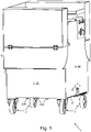
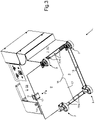
- the machine for processing and/or producing food designated overall by 1 and designed as a strip and dicer cutter, has a machine housing 2 and machine feet 3, which are provided for setting up the machine 1 on the floor 4 of a room.
- the machine housing has side walls 5A, 5B, 5C and a bottom plate 6.
- the side walls 5A, 5B, 5C and the bottom plate 6 define an in the Inner cavity not shown in the drawing, in which electrical and mechanical machine components are arranged, including a drive motor for a cutting gate, with which food can be cut into strips or cubes in a manner known per se.
- the base plate 6 and the side walls 5A, 5B, 5C protect the inner cavity from the ingress of dust and splash water.
- the machine feet 3 are connected to the base plate 6 of the machine housing 2 in such a way that the base plate 6 is spaced from the floor 4 by a gap 7 when the machine 1 is set up on the floor 4 .
- the vertical distance between the base plate 6 and the floor 4 is about 10 cm.
- the machine 1 has, on the underside of the base plate 6 facing away from the inner cavity of the machine housing 2, a cover plate 8 which can be detachably connected to the machine housing 2 and which covers the entire underside of the base plate 6 when it is connected to the machine housing 2.
- the cover plate 8 is waterproof and dustproof and consists of a material that can be easily cleaned, preferably plastic.
- the base plate 6 is also waterproof and dustproof and is preferably made of stainless steel.
- the cover plate 8 is mounted on the machine housing 2, so that any dirt that sprays against the machine 1 from below at the points where the cover plate 8 covers the base plate 6, cannot come into contact with the bottom plate 6.
- the cover plate 8 is removed from the base plate 6 and then cleaned separately from the machine 1, for example by washing or sprinkling with water. After the cover plate 8 has dried, it is mounted again on the base plate 6 or on the machine housing 2 and inserted into the in figure 5 brought assembly position shown, in which the cover plate 8 is arranged completely below the base plate 6 and parallel to this. In the assembly position, the cover plate 8 is preferably in direct contact with the underside of the base plate or is positioned at a distance of a few millimeters from the underside of the base plate 6 .
- a sensor not shown in detail in the drawing such as a button, is provided on the machine housing 2, which is in control connection with the drive motor of the machine 1 in such a way that the operation of the drive motor is blocked when the Cover plate 8 is not arranged in the assembly position.
- the machine can therefore only be operated when the cover plate 8 is in the assembly position.
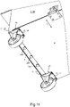
- the cover plate 8 can be moved between the assembly position ( 2 and 5 ) and the pre-assembly position ( 7 ) parallel to the plane spanned by the base plate 6 in a sliding direction 9 displaceable.
- a handle 11 is attached to an edge region 10 of the cover plate 8, which extends transversely to the sliding direction 9 of the sliding guide, and in the assembled position of the cover plate 8 above the cover plate 8 on an outer surface of the side wall 5B of the machine housing facing away from the inner cavity 2 is positioned ( 10 ).
- a retaining plate 12 which is connected to the handle 11 at an approximately angle and is fastened to the cover plate 8 with the aid of fastening elements such as screws or rivets.
- the handle 11 has an opening 13 for the fingers of a human hand to reach through.
- the plane spanned by the opening 13 is arranged transversely to the plane of extent of the cover plate 8 .
- the plane spanned by the opening 13 is arranged approximately parallel to the plane in which the side wall 5B extends ( 6 and 7 ).
- a latching element 14 is arranged, which is latched in the assembly position of the cover plate 8 with the handle 11 ( 1 , 2 and 10 ).
- the latching element has a shaft 15 which has a radial widening 16 at one end and an insertion bevel arranged thereon for the edge of the handle 11 bordering the opening 13 .
- the shank 15 is connected to the side wall 5B of the machine housing 2 at its other end remote from the enlargement 16 .
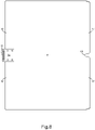
- the cover plate 8 On its opposite edge region 17 remote from the handle 11, the cover plate 8 has a support point 18 which interacts with a support element 19 arranged on the base plate 6 when the cover plate 8 is arranged in the assembly position. As in Fig.8 can be seen, the support point 18 is designed as an open-edged recess in the cover plate 8 .
- the support element 19 is essentially mushroom-shaped and has a shaft part which is connected to the base plate and which engages in the open-edged recess of the support point 18 when the cover plate 8 is in the assembly position. At its end remote from the base plate, the shaft part is connected to an approximately mushroom-shaped head part, on which the cover plate 8 is supported with its support point 18 when the cover plate 8 is in the assembly position.
- the sliding guide on the base plate 6 has two parallel, spaced-apart guides 20A, 20B running in the sliding direction, between which the cover plate 8 is held in a form-fitting manner transverse to the sliding direction 9 in the assembled position.
- Each of these guides 20A, 20B has a row with a plurality of approximately mushroom-shaped guide elements which are spaced apart from one another in the sliding direction 9 .
- the guide elements each have a shank connected to the base plate 6 and at their end remote from the base plate 6 an approximately mushroom-shaped head which is widened relative to the shank and which forms a projection protruding in the direction of the respective opposite guide 20B, 20A.
- the cover plate 8 rests on the projections when it is arranged between the guides 20B, 20A.
- the machine feet 3 are designed as rollers or castors on which the machine 1 can be moved.
- Each machine base 3 is arranged on a support plate 21 which has a first edge area 22 connected to the machine housing 2 and a second edge area 23 which is arranged underneath the underside of the base plate 6 .
- the second edge region 23 of each support plate 21 is spaced apart from the base plate 6 by a slot 24 . In the installed position, the cover plate 8 engages in the slot 24 with an edge region.
Landscapes
- Life Sciences & Earth Sciences (AREA)
- Engineering & Computer Science (AREA)
- Wood Science & Technology (AREA)
- Zoology (AREA)
- Food Science & Technology (AREA)
- Food-Manufacturing Devices (AREA)
Applications Claiming Priority (1)
| Application Number | Priority Date | Filing Date | Title |
|---|---|---|---|
| DE102021000490.6A DE102021000490B3 (de) | 2021-02-02 | 2021-02-02 | Maschine zum Verarbeiten und/oder Herstellen von Lebensmitteln |
Publications (3)
| Publication Number | Publication Date |
|---|---|
| EP4035534A1 true EP4035534A1 (fr) | 2022-08-03 |
| EP4035534B1 EP4035534B1 (fr) | 2023-11-15 |
| EP4035534C0 EP4035534C0 (fr) | 2023-11-15 |
Family
ID=80001485
Family Applications (1)
| Application Number | Title | Priority Date | Filing Date |
|---|---|---|---|
| EP22152856.5A Active EP4035534B1 (fr) | 2021-02-02 | 2022-01-24 | Machine à traiter et/ou à fabriquer des denrées alimentaires |
Country Status (2)
| Country | Link |
|---|---|
| EP (1) | EP4035534B1 (fr) |
| DE (1) | DE102021000490B3 (fr) |
Citations (3)
| Publication number | Priority date | Publication date | Assignee | Title |
|---|---|---|---|---|
| CN1295062C (zh) * | 2003-07-29 | 2007-01-17 | 郑运祚 | 食品切片机切肉碎片防止装置 |
| US7658135B2 (en) * | 2005-08-03 | 2010-02-09 | Giorgio Grasselli | Meat slicing machine |
| EP3315219A1 (fr) * | 2016-10-28 | 2018-05-02 | Fraunhofer-Gesellschaft zur Förderung der angewandten Forschung e.V. | Dispositif de nettoyage pour surfaces |
-
2021
- 2021-02-02 DE DE102021000490.6A patent/DE102021000490B3/de active Active
-
2022
- 2022-01-24 EP EP22152856.5A patent/EP4035534B1/fr active Active
Patent Citations (3)
| Publication number | Priority date | Publication date | Assignee | Title |
|---|---|---|---|---|
| CN1295062C (zh) * | 2003-07-29 | 2007-01-17 | 郑运祚 | 食品切片机切肉碎片防止装置 |
| US7658135B2 (en) * | 2005-08-03 | 2010-02-09 | Giorgio Grasselli | Meat slicing machine |
| EP3315219A1 (fr) * | 2016-10-28 | 2018-05-02 | Fraunhofer-Gesellschaft zur Förderung der angewandten Forschung e.V. | Dispositif de nettoyage pour surfaces |
Also Published As
| Publication number | Publication date |
|---|---|
| EP4035534B1 (fr) | 2023-11-15 |
| DE102021000490B3 (de) | 2022-06-09 |
| EP4035534C0 (fr) | 2023-11-15 |
Similar Documents
| Publication | Publication Date | Title |
|---|---|---|
| DE69302547T2 (de) | Reiniger für Borstenbett einer Maschine zum Schneiden von Flachmaterial | |
| CH659425A5 (de) | Vorrichtung zum anbringen horizontaler und vertikaler schnitte an plattenfoermigen objekten. | |
| DE4229840C2 (de) | Bürstenbefestigungskonstruktion für die Schneideauflagefläche in Zuschneidautomaten | |
| EP1356896A2 (fr) | Tampon d'aspiration | |
| EP4035534B1 (fr) | Machine à traiter et/ou à fabriquer des denrées alimentaires | |
| DE102015000983A1 (de) | Messerkopf für eine Produktschneidemaschine | |
| DE29613432U1 (de) | Geschirrspüler mit einem in getrennte Bereiche unterteilten Bodenschacht | |
| EP3141358A1 (fr) | Machine a decouper des produits de boulangerie comprenant un chariot de transport | |
| DE102013012098B4 (de) | Vorrichtung zum Ausstanzen von Teigstücken | |
| DE2942268A1 (de) | Vorrichtung zur reinigung eines laufenden bandes | |
| DE19805901A1 (de) | Saugreinigungswerkzeug, insbesondere Bodensaugdüse | |
| DE102018204045A1 (de) | Transportbandsystem mit Sensorhalter | |
| EP2807005B1 (fr) | Trancheuse de pain avec dispositif de nettoyage | |
| CH646815A5 (de) | Tastatur zur betaetigung von druckschaltern. | |
| EP4147621B1 (fr) | Dispositif de nettoyage d'une surface de sol pourvue d'éléments d'étanchéité latéraux | |
| DE102005041869A1 (de) | Staubsaugerdüse mit Bürstenleiste | |
| DE4016887C2 (fr) | ||
| EP1780449B1 (fr) | Machine à laver industrielle avec dispositif d'étanchéité entre la porte et l'organe d'actionnement ou de traction | |
| DE2003604C3 (de) | Schuhputzgerät | |
| EP2380714B1 (fr) | Machine de coupe de tranches dotée d'un intervalle de passage entre une paroi arrière de chariot et une plaque d'appui | |
| AT522661B1 (de) | Spülkorb für Spülmaschinen | |
| DE29700710U1 (de) | Vorrichtung zum Reinigen einer einen Schwamm aufweisenden Schwammscheibe | |
| DE9413348U1 (de) | Reinigungsvorrichtung für Backbleche | |
| EP1790266B1 (fr) | Buse d'aspiration pour aspirateur avec protection contre l'usure de la semelle d'aspiration | |
| DE202013006520U1 (de) | Vorrichtung zum Ausstanzen von Teigstücken |
Legal Events
| Date | Code | Title | Description |
|---|---|---|---|
| PUAI | Public reference made under article 153(3) epc to a published international application that has entered the european phase |
Free format text: ORIGINAL CODE: 0009012 |
|
| STAA | Information on the status of an ep patent application or granted ep patent |
Free format text: STATUS: THE APPLICATION HAS BEEN PUBLISHED |
|
| AK | Designated contracting states |
Kind code of ref document: A1 Designated state(s): AL AT BE BG CH CY CZ DE DK EE ES FI FR GB GR HR HU IE IS IT LI LT LU LV MC MK MT NL NO PL PT RO RS SE SI SK SM TR |
|
| STAA | Information on the status of an ep patent application or granted ep patent |
Free format text: STATUS: REQUEST FOR EXAMINATION WAS MADE |
|
| 17P | Request for examination filed |
Effective date: 20230124 |
|
| RBV | Designated contracting states (corrected) |
Designated state(s): AL AT BE BG CH CY CZ DE DK EE ES FI FR GB GR HR HU IE IS IT LI LT LU LV MC MK MT NL NO PL PT RO RS SE SI SK SM TR |
|
| GRAP | Despatch of communication of intention to grant a patent |
Free format text: ORIGINAL CODE: EPIDOSNIGR1 |
|
| STAA | Information on the status of an ep patent application or granted ep patent |
Free format text: STATUS: GRANT OF PATENT IS INTENDED |
|
| RIC1 | Information provided on ipc code assigned before grant |
Ipc: A22C 17/00 20060101AFI20230622BHEP |
|
| INTG | Intention to grant announced |
Effective date: 20230712 |
|
| GRAS | Grant fee paid |
Free format text: ORIGINAL CODE: EPIDOSNIGR3 |
|
| GRAA | (expected) grant |
Free format text: ORIGINAL CODE: 0009210 |
|
| STAA | Information on the status of an ep patent application or granted ep patent |
Free format text: STATUS: THE PATENT HAS BEEN GRANTED |
|
| AK | Designated contracting states |
Kind code of ref document: B1 Designated state(s): AL AT BE BG CH CY CZ DE DK EE ES FI FR GB GR HR HU IE IS IT LI LT LU LV MC MK MT NL NO PL PT RO RS SE SI SK SM TR |
|
| REG | Reference to a national code |
Ref country code: CH Ref legal event code: EP Ref country code: GB Ref legal event code: FG4D Free format text: NOT ENGLISH |
|
| REG | Reference to a national code |
Ref country code: DE Ref legal event code: R096 Ref document number: 502022000252 Country of ref document: DE |
|
| REG | Reference to a national code |
Ref country code: IE Ref legal event code: FG4D Free format text: LANGUAGE OF EP DOCUMENT: GERMAN |
|
| U01 | Request for unitary effect filed |
Effective date: 20231121 |
|
| U07 | Unitary effect registered |
Designated state(s): AT BE BG DE DK EE FI FR IT LT LU LV MT NL PT SE SI Effective date: 20231128 |
|
| U20 | Renewal fee for the european patent with unitary effect paid |
Year of fee payment: 3 Effective date: 20231219 |
|
| PG25 | Lapsed in a contracting state [announced via postgrant information from national office to epo] |
Ref country code: GR Free format text: LAPSE BECAUSE OF FAILURE TO SUBMIT A TRANSLATION OF THE DESCRIPTION OR TO PAY THE FEE WITHIN THE PRESCRIBED TIME-LIMIT Effective date: 20240216 |
|
| PG25 | Lapsed in a contracting state [announced via postgrant information from national office to epo] |
Ref country code: IS Free format text: LAPSE BECAUSE OF FAILURE TO SUBMIT A TRANSLATION OF THE DESCRIPTION OR TO PAY THE FEE WITHIN THE PRESCRIBED TIME-LIMIT Effective date: 20240315 |
|
| PG25 | Lapsed in a contracting state [announced via postgrant information from national office to epo] |
Ref country code: ES Free format text: LAPSE BECAUSE OF FAILURE TO SUBMIT A TRANSLATION OF THE DESCRIPTION OR TO PAY THE FEE WITHIN THE PRESCRIBED TIME-LIMIT Effective date: 20231115 |
|
| PG25 | Lapsed in a contracting state [announced via postgrant information from national office to epo] |
Ref country code: IS Free format text: LAPSE BECAUSE OF FAILURE TO SUBMIT A TRANSLATION OF THE DESCRIPTION OR TO PAY THE FEE WITHIN THE PRESCRIBED TIME-LIMIT Effective date: 20240315 Ref country code: GR Free format text: LAPSE BECAUSE OF FAILURE TO SUBMIT A TRANSLATION OF THE DESCRIPTION OR TO PAY THE FEE WITHIN THE PRESCRIBED TIME-LIMIT Effective date: 20240216 Ref country code: ES Free format text: LAPSE BECAUSE OF FAILURE TO SUBMIT A TRANSLATION OF THE DESCRIPTION OR TO PAY THE FEE WITHIN THE PRESCRIBED TIME-LIMIT Effective date: 20231115 |
|
| PG25 | Lapsed in a contracting state [announced via postgrant information from national office to epo] |
Ref country code: RS Free format text: LAPSE BECAUSE OF FAILURE TO SUBMIT A TRANSLATION OF THE DESCRIPTION OR TO PAY THE FEE WITHIN THE PRESCRIBED TIME-LIMIT Effective date: 20231115 Ref country code: PL Free format text: LAPSE BECAUSE OF FAILURE TO SUBMIT A TRANSLATION OF THE DESCRIPTION OR TO PAY THE FEE WITHIN THE PRESCRIBED TIME-LIMIT Effective date: 20231115 Ref country code: NO Free format text: LAPSE BECAUSE OF FAILURE TO SUBMIT A TRANSLATION OF THE DESCRIPTION OR TO PAY THE FEE WITHIN THE PRESCRIBED TIME-LIMIT Effective date: 20240215 Ref country code: HR Free format text: LAPSE BECAUSE OF FAILURE TO SUBMIT A TRANSLATION OF THE DESCRIPTION OR TO PAY THE FEE WITHIN THE PRESCRIBED TIME-LIMIT Effective date: 20231115 |
|
| PG25 | Lapsed in a contracting state [announced via postgrant information from national office to epo] |
Ref country code: CZ Free format text: LAPSE BECAUSE OF FAILURE TO SUBMIT A TRANSLATION OF THE DESCRIPTION OR TO PAY THE FEE WITHIN THE PRESCRIBED TIME-LIMIT Effective date: 20231115 |
|
| PG25 | Lapsed in a contracting state [announced via postgrant information from national office to epo] |
Ref country code: SK Free format text: LAPSE BECAUSE OF FAILURE TO SUBMIT A TRANSLATION OF THE DESCRIPTION OR TO PAY THE FEE WITHIN THE PRESCRIBED TIME-LIMIT Effective date: 20231115 |
|
| PG25 | Lapsed in a contracting state [announced via postgrant information from national office to epo] |
Ref country code: SM Free format text: LAPSE BECAUSE OF FAILURE TO SUBMIT A TRANSLATION OF THE DESCRIPTION OR TO PAY THE FEE WITHIN THE PRESCRIBED TIME-LIMIT Effective date: 20231115 Ref country code: SK Free format text: LAPSE BECAUSE OF FAILURE TO SUBMIT A TRANSLATION OF THE DESCRIPTION OR TO PAY THE FEE WITHIN THE PRESCRIBED TIME-LIMIT Effective date: 20231115 Ref country code: RO Free format text: LAPSE BECAUSE OF FAILURE TO SUBMIT A TRANSLATION OF THE DESCRIPTION OR TO PAY THE FEE WITHIN THE PRESCRIBED TIME-LIMIT Effective date: 20231115 Ref country code: CZ Free format text: LAPSE BECAUSE OF FAILURE TO SUBMIT A TRANSLATION OF THE DESCRIPTION OR TO PAY THE FEE WITHIN THE PRESCRIBED TIME-LIMIT Effective date: 20231115 |
|
| REG | Reference to a national code |
Ref country code: DE Ref legal event code: R097 Ref document number: 502022000252 Country of ref document: DE |
|
| PG25 | Lapsed in a contracting state [announced via postgrant information from national office to epo] |
Ref country code: MC Free format text: LAPSE BECAUSE OF FAILURE TO SUBMIT A TRANSLATION OF THE DESCRIPTION OR TO PAY THE FEE WITHIN THE PRESCRIBED TIME-LIMIT Effective date: 20231115 |
|
| PG25 | Lapsed in a contracting state [announced via postgrant information from national office to epo] |
Ref country code: MC Free format text: LAPSE BECAUSE OF FAILURE TO SUBMIT A TRANSLATION OF THE DESCRIPTION OR TO PAY THE FEE WITHIN THE PRESCRIBED TIME-LIMIT Effective date: 20231115 |
|
| PLBE | No opposition filed within time limit |
Free format text: ORIGINAL CODE: 0009261 |
|
| STAA | Information on the status of an ep patent application or granted ep patent |
Free format text: STATUS: NO OPPOSITION FILED WITHIN TIME LIMIT |
|
| 26N | No opposition filed |
Effective date: 20240819 |
|
| PG25 | Lapsed in a contracting state [announced via postgrant information from national office to epo] |
Ref country code: IE Free format text: LAPSE BECAUSE OF NON-PAYMENT OF DUE FEES Effective date: 20240124 |
|
| PG25 | Lapsed in a contracting state [announced via postgrant information from national office to epo] |
Ref country code: IE Free format text: LAPSE BECAUSE OF NON-PAYMENT OF DUE FEES Effective date: 20240124 |
|
| U20 | Renewal fee for the european patent with unitary effect paid |
Year of fee payment: 4 Effective date: 20250131 |
|
| PG25 | Lapsed in a contracting state [announced via postgrant information from national office to epo] |
Ref country code: CY Free format text: LAPSE BECAUSE OF FAILURE TO SUBMIT A TRANSLATION OF THE DESCRIPTION OR TO PAY THE FEE WITHIN THE PRESCRIBED TIME-LIMIT; INVALID AB INITIO Effective date: 20220124 |
|
| REG | Reference to a national code |
Ref country code: CH Ref legal event code: PL |
|
| PG25 | Lapsed in a contracting state [announced via postgrant information from national office to epo] |
Ref country code: CH Free format text: LAPSE BECAUSE OF NON-PAYMENT OF DUE FEES Effective date: 20250131 |
|
| PG25 | Lapsed in a contracting state [announced via postgrant information from national office to epo] |
Ref country code: TR Free format text: LAPSE BECAUSE OF FAILURE TO SUBMIT A TRANSLATION OF THE DESCRIPTION OR TO PAY THE FEE WITHIN THE PRESCRIBED TIME-LIMIT Effective date: 20231115 |