EP4035534A1 - Maschine zum verarbeiten und/oder herstellen von lebensmitteln - Google Patents
Maschine zum verarbeiten und/oder herstellen von lebensmitteln Download PDFInfo
- Publication number
- EP4035534A1 EP4035534A1 EP22152856.5A EP22152856A EP4035534A1 EP 4035534 A1 EP4035534 A1 EP 4035534A1 EP 22152856 A EP22152856 A EP 22152856A EP 4035534 A1 EP4035534 A1 EP 4035534A1
- Authority
- EP
- European Patent Office
- Prior art keywords
- machine
- cover plate
- base plate
- underside
- plate
- Prior art date
- Legal status (The legal status is an assumption and is not a legal conclusion. Google has not performed a legal analysis and makes no representation as to the accuracy of the status listed.)
- Granted
Links
Images





Classifications
-
- A—HUMAN NECESSITIES
- A22—BUTCHERING; MEAT TREATMENT; PROCESSING POULTRY OR FISH
- A22C—PROCESSING MEAT, POULTRY, OR FISH
- A22C17/00—Other devices for processing meat or bones
Definitions
- the invention relates to a machine for processing and/or producing food, with a machine housing and with machine feet for setting up the machine on the floor of a room, the machine housing having a base plate and side walls that delimit an inner cavity in which electrical and/or mechanical machine components are arranged, the machine feet being connected to the bottom plate of the machine housing in such a way that this is spaced from the floor by a gap when the machine is placed on the floor.
- Such machines are made of one Product catalog of the applicant from the year 2019 with the title "Real power packs - you will love them "Known and are sold by the applicant with great success. You can, for example, as a cutting machine, in particular strip and dicer for meat, sausage, cheese, vegetables or similar foods, as a frozen meat cutter, as a curing machine or as a mixing and tumbling machine.
- the Machines are used, for example, in food production and processing plants as well as in butcher shops.
- the machine housing of the previously known machines has a base plate and boundary walls which protect the inner cavity from the ingress of dirt and moisture.
- Machine feet are usually provided on the machine housing, which are designed in such a way that the base plate is arranged approximately 10 cm above the floor. This allows the floor under the machine to be easily cleaned, for example using a high-pressure cleaner, without removing the machine from its location.
- the object is therefore to create a machine of the type mentioned at the outset in which soiling of the base plate of the machine housing can be avoided in a simple manner even if the base plate is arranged close to the floor, for example at a distance of about 10 cm .
- this object is achieved with the features of claim 1.
- the machine has, on the underside of the base plate facing away from the inner cavity of the machine housing, a cover plate that can be detachably connected to the machine housing and covers the underside of the base plate over a large area when it is connected to the machine housing.
- the cover plate is mounted under the base plate, so that any dirt that sprays against the machine from below can come into contact with the cover plate, but not with the areas of the underside of the base plate covered by it.
- the cover plate is removed from the base plate so that it can easily be cleaned separately from the machine, for example by hosing down with water, by immersing in a cleaning liquid and/or by rinsing in a dishwasher .
- the cover plate After being brought into contact with the cleaning liquid, the cover plate is preferably first dried, for example by removing the cleaning liquid from the cover plate with a rubber squeegee or by simply arranging it so that the water or the cleaning liquid runs off it. After cleaning, the cover plate is reinstalled on the base plate or on the machine housing.
- the cover plate is preferably adapted to the base plate of the machine housing in such a way that it covers at least the majority of the underside of the base plate, in particular at least 80%, optionally at least 90% and preferably at least 95% of the underside of the base plate.
- the machine feet can be arranged in the relatively small part of the base plate that is not covered by the cover plate.
- cover plate can be replaced relatively inexpensively if it is damaged or no longer meets hygiene regulations. So that the machine can be put back into operation as quickly as possible after cleaning, the machine can have two cover plates which can be mounted alternately on the base plate. The machine can then continue to be operated with the other cover plate when cleaning or drying one cover plate.
- the cover plate is preferably made of a plastic that is easy to clean.
- the machine has a sensor for detecting the mounting position of the cover plate, which is in control connection with a drive motor of the machine such that the operation of the drive motor is blocked when the cover plate is not arranged in the mounting position. The machine can then only be operated if the base plate is protected from dirt by the cover plate.
- the cover plate comes to rest flat on the underside of the base plate when the cover plate is connected to the machine housing. This protects the base plate even better against dirt.
- the cover plate can be mounted at a small distance from the base plate, for example at a maximum of 5 mm, possibly a maximum of 3 and preferably a maximum of 1 mm from the base plate.
- the bottom plate is effectively protected from dirt on its underside, in particular if the space between the cover plate and the bottom plate is sealed off from the outside by a sealing lip or similar seal.
- the cover plate can be displaced by means of a sliding guide between an assembly position in which the cover plate covers the underside of the base plate and a pre-assembly position in which the cover plate releases the underside of the base plate, parallel to the plane of extension of the base plate relative to the latter. This enables the cover plate to be mounted easily and quickly on or removed from the base plate.
- a handle is attached to an edge region of the cover plate, which extends transversely to the sliding direction of the sliding guide, which is in the assembled position of the cover plate above the Cover plate is positioned on an inner cavity facing away from the outer surface of a side wall of the machine housing.
- the cover plate can thus be gripped by the handle and easily pulled out of or pushed into the sliding guide.
- the handle is located on the side wall of the machine body where it is protected from damage.
- the handle which is separated from the base plate, can be hung up vertically so that it can dry quickly.
- the handle preferably has an opening for the fingers of a human hand to pass through.
- a latching element is arranged on the side wall of the machine housing, on which the handle is positioned in the assembly position of the cover plate, which is latched to the handle in the assembly position of the cover plate.
- the handle is preferably arranged approximately centrally on an edge region of the cover plate that is adjacent thereto. The handle latched to the latching element in the assembly position secures the cover plate against accidental displacement in the guide rail and prevents the cover plate from bending down between the guides of the sliding guide.
- a support point can be provided on the opposite edge region of the cover plate remote from the handle, which works together with a support element arranged on the base plate when the cover plate is arranged in the assembly position.
- the sliding guide has two parallel, spaced-apart guides running in the sliding direction, between which the cover plate is held in a form-fitting manner transverse to the sliding direction in the installed position, each of these guides having a row with a plurality of preferably mushroom-shaped guide elements which are in the sliding direction are spaced from one another, the guide elements each having one with the bottom plate connected shaft and have at their end remote from the base plate in the direction of the respective opposite guide protruding projection on which the cover plate comes to rest in the assembled position. If necessary, the guides can then be cleaned relatively easily, since they are accessible from the side wall of the machine housing adjacent to them.
- At least one machine foot is arranged on a support plate which has a first edge area connected to the machine housing and a second edge area which is arranged underneath the underside of the base plate and separated from it by a slot is spaced, wherein the cover plate engages in the assembled position in the slot.
- the cover plate located in the assembly position covers the underside of the base plate even in the area of the machine feet almost to the edges of the base plate running parallel to the sliding direction of the sliding guide.
- rollers and/or castors are attached to the machine feet.
- the machine can then be easily maneuvered and moved on the floor.
- the machine for processing and/or producing food designated overall by 1 and designed as a strip and dicer cutter, has a machine housing 2 and machine feet 3, which are provided for setting up the machine 1 on the floor 4 of a room.
- the machine housing has side walls 5A, 5B, 5C and a bottom plate 6.
- the side walls 5A, 5B, 5C and the bottom plate 6 define an in the Inner cavity not shown in the drawing, in which electrical and mechanical machine components are arranged, including a drive motor for a cutting gate, with which food can be cut into strips or cubes in a manner known per se.
- the base plate 6 and the side walls 5A, 5B, 5C protect the inner cavity from the ingress of dust and splash water.
- the machine feet 3 are connected to the base plate 6 of the machine housing 2 in such a way that the base plate 6 is spaced from the floor 4 by a gap 7 when the machine 1 is set up on the floor 4 .
- the vertical distance between the base plate 6 and the floor 4 is about 10 cm.
- the machine 1 has, on the underside of the base plate 6 facing away from the inner cavity of the machine housing 2, a cover plate 8 which can be detachably connected to the machine housing 2 and which covers the entire underside of the base plate 6 when it is connected to the machine housing 2.
- the cover plate 8 is waterproof and dustproof and consists of a material that can be easily cleaned, preferably plastic.
- the base plate 6 is also waterproof and dustproof and is preferably made of stainless steel.
- the cover plate 8 is mounted on the machine housing 2, so that any dirt that sprays against the machine 1 from below at the points where the cover plate 8 covers the base plate 6, cannot come into contact with the bottom plate 6.
- the cover plate 8 is removed from the base plate 6 and then cleaned separately from the machine 1, for example by washing or sprinkling with water. After the cover plate 8 has dried, it is mounted again on the base plate 6 or on the machine housing 2 and inserted into the in figure 5 brought assembly position shown, in which the cover plate 8 is arranged completely below the base plate 6 and parallel to this. In the assembly position, the cover plate 8 is preferably in direct contact with the underside of the base plate or is positioned at a distance of a few millimeters from the underside of the base plate 6 .
- a sensor not shown in detail in the drawing such as a button, is provided on the machine housing 2, which is in control connection with the drive motor of the machine 1 in such a way that the operation of the drive motor is blocked when the Cover plate 8 is not arranged in the assembly position.
- the machine can therefore only be operated when the cover plate 8 is in the assembly position.
- the cover plate 8 can be moved between the assembly position ( 2 and 5 ) and the pre-assembly position ( 7 ) parallel to the plane spanned by the base plate 6 in a sliding direction 9 displaceable.
- a handle 11 is attached to an edge region 10 of the cover plate 8, which extends transversely to the sliding direction 9 of the sliding guide, and in the assembled position of the cover plate 8 above the cover plate 8 on an outer surface of the side wall 5B of the machine housing facing away from the inner cavity 2 is positioned ( 10 ).
- a retaining plate 12 which is connected to the handle 11 at an approximately angle and is fastened to the cover plate 8 with the aid of fastening elements such as screws or rivets.
- the handle 11 has an opening 13 for the fingers of a human hand to reach through.
- the plane spanned by the opening 13 is arranged transversely to the plane of extent of the cover plate 8 .
- the plane spanned by the opening 13 is arranged approximately parallel to the plane in which the side wall 5B extends ( 6 and 7 ).
- a latching element 14 is arranged, which is latched in the assembly position of the cover plate 8 with the handle 11 ( 1 , 2 and 10 ).
- the latching element has a shaft 15 which has a radial widening 16 at one end and an insertion bevel arranged thereon for the edge of the handle 11 bordering the opening 13 .
- the shank 15 is connected to the side wall 5B of the machine housing 2 at its other end remote from the enlargement 16 .
- the cover plate 8 On its opposite edge region 17 remote from the handle 11, the cover plate 8 has a support point 18 which interacts with a support element 19 arranged on the base plate 6 when the cover plate 8 is arranged in the assembly position. As in Fig.8 can be seen, the support point 18 is designed as an open-edged recess in the cover plate 8 .
- the support element 19 is essentially mushroom-shaped and has a shaft part which is connected to the base plate and which engages in the open-edged recess of the support point 18 when the cover plate 8 is in the assembly position. At its end remote from the base plate, the shaft part is connected to an approximately mushroom-shaped head part, on which the cover plate 8 is supported with its support point 18 when the cover plate 8 is in the assembly position.
- the sliding guide on the base plate 6 has two parallel, spaced-apart guides 20A, 20B running in the sliding direction, between which the cover plate 8 is held in a form-fitting manner transverse to the sliding direction 9 in the assembled position.
- Each of these guides 20A, 20B has a row with a plurality of approximately mushroom-shaped guide elements which are spaced apart from one another in the sliding direction 9 .
- the guide elements each have a shank connected to the base plate 6 and at their end remote from the base plate 6 an approximately mushroom-shaped head which is widened relative to the shank and which forms a projection protruding in the direction of the respective opposite guide 20B, 20A.
- the cover plate 8 rests on the projections when it is arranged between the guides 20B, 20A.
- the machine feet 3 are designed as rollers or castors on which the machine 1 can be moved.
- Each machine base 3 is arranged on a support plate 21 which has a first edge area 22 connected to the machine housing 2 and a second edge area 23 which is arranged underneath the underside of the base plate 6 .
- the second edge region 23 of each support plate 21 is spaced apart from the base plate 6 by a slot 24 . In the installed position, the cover plate 8 engages in the slot 24 with an edge region.
Landscapes
- Life Sciences & Earth Sciences (AREA)
- Engineering & Computer Science (AREA)
- Wood Science & Technology (AREA)
- Zoology (AREA)
- Food Science & Technology (AREA)
- Food-Manufacturing Devices (AREA)
Abstract
Description
- Die Erfindung betrifft eine Maschine zum Verarbeiten und/oder Herstellen von Lebensmitteln, mit einem Maschinengehäuse und mit Maschinenfüßen zum Aufstellen der Maschine auf dem Fußboden eines Raumes, wobei das Maschinengehäuse eine Bodenplatte und Seitenwände aufweist, die eine Innenhöhlung begrenzen, in der elektrische und/oder mechanische Maschinenkomponenten angeordnet sind, wobei die Maschinenfüße derart mit der Bodenplatte des Maschinengehäuses verbunden sind, dass diese durch einen Zwischenraum vom Fußboden beabstandet ist, wenn die Maschine auf dem Fußboden aufgestellt ist.
- Derartige Maschinen sind aus einem Produktkatalog der Anmelderin aus dem Jahr 2019 mit dem Titel "Echte Kraftpakete - sie werden sie lieben" bekannt und werden von der Anmelderin mit großem Erfolg vertrieben. Sie können beispielsweise als Schneidemaschine, insbesondere Streifen- und Würfelschneider für Fleisch, Wurst, Käse, Gemüse oder dergleichen Lebensmittel, als Gefrierfleischschneider, als Pökelmaschine oder als Misch- und Tumblemaschine ausgestaltet sein. Die Maschinen werden u.a. in Lebensmittel-Produktions- und Verarbeitungsbetrieben sowie in Metzgereien verwendet.
- Das Maschinengehäuse der vorbekannten Maschinen hat eine Bodenplatte und Begrenzungswände, welche die Innenhöhlung vor dem Eindringen von Schmutz und Feuchtigkeit schützen. Üblicherweise sind an dem Maschinengehäuse Maschinenfüße vorgesehen, die derart ausgestaltet sind, dass die Bodenplatte in etwa 10 cm über dem Fußboden angeordnet ist. Hierdurch kann der Fußboden unter der Maschine auf einfache Weise beispielsweise mit Hilfe eines Hochdruckreinigers gereinigt werden, ohne die Maschine von ihrem Standort zu entfernen.
- Nachteilig ist dabei jedoch, dass die Unterseite der Bodenplatte wegen ihres geringen Abstands zum Fußboden beim Reinigen nur schwer zugänglich ist. Auch wenn eine Reinigung der Bodenunterseite theoretisch möglich ist, wird sie wegen des hohen Arbeitsaufwands meist nicht gemacht. Auf diese Weise sammeln sich schon nach kurzer Zeit Reste aus verklebten Fleischresten und anderen Verunreinigungen dort an. Dies ist, gerade im Bereich der Lebensmitteltechnik, ein großes Hygieneproblem. Natürlich wäre es möglich, die Maschine mittels eines Hebezeugs anzuheben, doch -aufgrund des Maschinengewichts und der Größe- können viele Maschinen aus Sicherheitsgründen nicht einfach problemlos angehoben werden, um sie zu reinigen. Die Gefahr einer Verschmutzung des Maschinenbodens könnte zwar auch dadurch reduziert werden, dass höhere Maschinenfüße an dem Maschinengehäuse angebracht werden, so dass die Bodenplatte des Maschinengehäuses dann in einem größeren Abstand zum Fußboden angeordnet wäre. Da hätte aber den Nachteil, dass der Raum über dem Fußboden nicht oder nur schlecht für die Maschine genutzt werden könnte.
- Es besteht deshalb die Aufgabe, eine Maschine der eingangs genannten Art zu schaffen, bei welcher eine Verschmutzung der Bodenplatte des Maschinengehäuses auf einfache Weise auch dann vermieden werden kann, wenn die Bodenplatte dicht über dem Fußboden angeordnet ist, beispielsweise in einem Abstand von etwa 10 cm.
- Erfindungsgemäß wird diese Aufgabe mit den Merkmalen des Patentanspruchs 1 gelöst. Diese sehen bei einer Maschine der eingangs genannten Art vor, dass die Maschine an der der Innenhöhlung des Maschinengehäuses abgewandten Unterseite der Bodenplatte eine lösbar mit dem Maschinengehäuse verbindbare Abdeckplatte aufweist, welche die Unterseite der Bodenplatte flächig abdeckt, wenn sie mit dem Maschinengehäuse verbunden ist.
- Während des Betriebs der Maschine und bei der Reinigung des unter der Maschine befindlichen Fußbodens beispielsweise durch Abspritzen mit einem Hochdruckreiniger ist die Abdeckplatte unter dem Bodenplatte montiert, so dass eventuelle Verschmutzungen, die von unten gegen die Maschine spritzen, zwar mit der Abdeckplatte, nicht aber den durch diese abgedeckten Bereichen der Unterseite der Bodenplatte in Kontakt geraten können. Um die Maschine an ihrer Unterseite zu reinigen, wird die Abdeckplatte von der Bodenplatte entfernt, so dass sie auf einfache Weise getrennt von der Maschine gereinigt werden kann, beispielsweise durch Abspritzen mit Wasser, durch Eintauchen in eine Reinigungsflüssigkeit und/oder durch Spülen in einer Spülmaschine. Vorzugsweise wird die Abdeckplatte nach dem Inkontaktbringen mit der Reinigungsflüssigkeit zunächst getrocknet, beispielsweise in dem die Reinigungsflüssigkeit mit einem Gummiabzieher von der Abdeckplatte entfernt wird oder diese einfach so angeordnet wird, dass das Wasser bzw. die Reinigungsflüssigkeit von ihr abläuft. Nach der Reinigung wird die Abdeckplatte wieder an der Bodenplatte bzw. am Maschinengehäuse montiert. Die Abdeckplatte ist bevorzugt derart an die Bodenplatte des Maschinengehäuses angepasst, dass sie zumindest den überwiegenden Teil der Unterseite der Bodenplatte abdeckt, insbesondere mindestens 80%, gegebenenfalls mindestens 90% und bevorzugt mindestens 95% der Unterseite der Bodenplatte. In dem relativ keinen, nicht durch die Abdeckplatte abgedeckten Teil der Bodenplatte können die Maschinenfüße angeordnet sein.
- Erwähnt werden soll noch, dass die Abdeckplatte relativ kostengünstig ersetzt werden kann, sollte sie beschädigt sein oder nicht mehr den Hygienevorschriften entsprechen. Damit die Maschine nach dem Reinigen möglichst schnell wieder in Betrieb genommen werden kann, kann die Maschine zwei Abdeckplatten aufweisen, die wechselweise an der Bodenplatte montiert werden können. Dann kann die Maschine beim Reinigen bzw. Trocknen der einen Abdeckplatte mit der jeweils anderen Abdeckplatte weiterbetrieben werden. Die Abdeckplatte besteht vorzugsweise aus einem leicht zu reinigenden Kunststoff.
- Bei einer Weiterbildung der Erfindung hat die Maschine einen Sensor zum Detektieren der Montagestellung der Abdeckplatte, der derart mit einem Antriebsmotor der Maschine in Steuerverbindung steht, dass der Betrieb des Antriebsmotors gesperrt ist, wenn die Abdeckplatte nicht in der Montagestellung angeordnet ist. Die Maschine kann dann nur betrieben werden, wenn die Bodenplatte durch die Abdeckplatte vor Verschmutzung geschützt ist.
- Bei einer bevorzugten Ausgestaltung der Erfindung kommt die Abdeckplatte flächig an der Unterseite der Bodenplatte zur Anlage, wenn die Abdeckplatte mit dem Maschinengehäuse verbunden ist. Hierdurch wird die Bodenplatte noch besser vor Verschmutzung geschützt. Es sind aber auch andere Ausgestaltungen denkbar, bei denen die Abdeckplatte in geringem Abstand zur Bodenplatte montiert sein kann, beispielsweise in maximal 5 mm, ggf. maximal 3 und bevorzugt maximal 1 mm Abstand zur Bodenplatte. Auch hierbei wird die Bodenplatte wirksam vor Verschmutzung an ihrer Unterseite geschützt, insbesondere wenn der Zwischenraum zwischen der Abdeckplatte und der Bodenplatte durch eine Dichtlippe oder dergleichen Dichtung nach außen hin abgedichtet ist.
- Bei einer vorteilhaften Ausführungsform der Maschine ist die Abdeckplatte mittels einer Schiebeführung zwischen einer Montagestellung, in der die Abdeckplatte die Unterseite der Bodenplatte abdeckt, und einer Vormontagestellung, in der die Abdeckplatte die Unterseite der Bodenplatte freigibt, parallel zur Erstreckungsebene der Bodenplatte relativ zu dieser verschiebbar. Dies ermöglich eine einfache und schnelle Montage der Abdeckplatte an bzw. eine Demontage der Abdeckplatte von der Bodenplatte.
- Bei einer zweckmäßigen Ausgestaltung der Erfindung ist an einem Randbereich der Abdeckplatte, der sich quer zur Schieberichtung der Schiebeführung erstreckt, ein Handgriff angebracht, der in Montagestellung der Abdeckplatte oberhalb der Abdeckplatte an einer der Innenhöhlung abgewandten Außenfläche einer Seitenwand des Maschinengehäuses positioniert ist. Somit kann die Abdeckplatte an dem Handgriff ergriffen und auch einfache Weise aus der Schiebeführung herausgezogen oder in diese hineingeschoben werden. Wenn die Abdeckplatte an der Bodenplatte montiert ist, ist der Handgriff an der Seitenwand des Maschinengehäuses angeordnet, wo er vor Beschädigung geschützt ist. Mittels des Handgriffs, kann die von der Bodenplatte getrennte Abdeckplatte senkrecht aufgehängt werden, so dass eine schnelle Trocknung möglich ist. Der Handgriff weist bevorzugt eine Öffnung für den Durchtritt der Finger einer menschlichen Hand auf.
- Vorteilhaft ist, wenn an der Seitenwand des Maschinengehäuses, an welcher der Handgriff in Montagestellung der Abdeckplatte positioniert ist, ein Rastelement angeordnet ist, das in Montagestellung der Abdeckplatte mit dem Handgriff verrastet ist. Der Handgriff ist bevorzugt etwa mittig an einem dazu benachbarten Randbereich der Abdeckplatte angeordnet. Durch den in Montagestellung mit dem Rastelement verrasteten Handgriff wird Abdeckplatte einerseits gegen versehentliches Verschieben in der Führungsschiene gesichert und andererseits wird vermieden, dass sich die Abdeckplatte zwischen den Führungen der Schiebeführung nach unten durchbiegt. Bei Bedarf kann an dem vom Handgriff entfernten, gegenüberliegenden Randbereich der Abdeckplatte eine Stützstelle vorgesehen sein, die mit einem an der Bodenplatte angeordneten Stützelement zusammenwirkt, wenn die Abdeckplatte in der Montagestellung angeordnet ist.
- Bei einer Weiterbildung der Erfindung hat die Schiebführung zwei parallel zueinander beabstandete, in Schiebrichtung verlaufende Führungen, zwischen denen die Abdeckplatte in Montagestellung quer zur Schieberichtung formschlüssig gehalten ist, wobei jede dieser Führungen jeweils eine Reihe mit mehreren, vorzugsweise pilzförmig ausgestalteten Führungselementen aufweist, die in Schiebrichtung zueinander beabstandet sind, wobei die Führungselemente jeweils einen mit der Bodenplatte verbunden Schaft und an ihrem von der Bodenplatte entfernten Ende einen in Richtung auf die jeweils gegenüberliegende Führung vorstehenden Vorsprung haben, an dem die Abdeckplatte in Montagestellung zur Auflage kommt. Die Führungen lassen sich dann bei Bedarf relativ leicht reinigen, da sie von der zu ihnen benachbarten Seitenwand des Maschinengehäuses aus zugänglich sind.
- Bei einer vorteilhaften Ausführungsform der Erfindung ist mindestens ein Maschinenfuß, vorzugsweise sind alle Maschinenfüße, an einer Trägerplatte angeordnet ist, die einen ersten, mit dem Maschinengehäuse verbunden Randbereich und einen zweiten Randbereich aufweist, der unterhalb der Unterseite der Bodenplatte angeordnet und durch einen Schlitz von dieser beabstandet ist, wobei die Abdeckplatte in Montagestellung in den Schlitz eingreift. Somit deckt die in Montagestellung befindliche Abdeckplatte die Unterseite der Bodenplatte sogar im Bereich der Maschinenfüße bis fast an die parallel zur Schieberichtung der Schiebführung verlaufenden Ränder der Bodenplatte ab.
- Bei einer zweckmäßigen Ausgestaltung der Erfindung sind an den Maschinenfüßen Rollen und/oder Lenkrollen angebracht. Die Maschine kann dann auf dem Fußboden auf einfache Weise rangiert und verschoben werden.
- Nachstehend ist ein Ausführungsbeispiel der Erfindung anhand der Zeichnung näher erläutert. Es zeigt
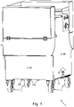
- Fig. 1
- eine perspektivische Ansicht auf die Schmalseite einer Maschine zum Verarbeiten und/oder Herstellen von Lebensmitteln,
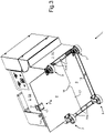
- Fig. 2
- eine perspektivische Ansicht auf die Unterseite der Maschine, wobei eine Abdeckplatte in Montagestellung angeordnet ist,
- Fig. 3
- eine perspektivische Ansicht auf die Unterseite der Maschine, wobei die Abdeckplatte teilweise aus einer Schiebeführung herausgezogen ist,
- Fig. 4
- eine Seitenansicht auf die Breitseite der Maschine,
- Fig. 5
- eine Aufsicht auf die Unterseite der Maschine,
- Fig. 6
- eine perspektivische Seitenansicht der Maschine, wobei die Abdeckplatte teilweise aus der Schiebeführung herausgezogen ist,
- Fig. 7
- eine Darstellung ähnlich
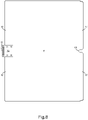
Fig. 6 , wobei jedoch die Abdeckplatte in einer Vormontagestellung angeordnet ist, in der sie vollständig aus der Schiebeführung herausgezogen ist, - Fig. 8
- eine Aufsicht auf die Unterseite der Abdeckplatte,
- Fig. 9
- eine Stirnseite der Abdeckplatte, an der ein Handgriff angeordnet ist,
- Fig. 10
- einen vergrößerten Ausschnitt aus
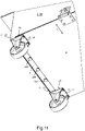
Fig. 2 , welcher einen Handgriff zeigt, und - Fig. 11
- einen vergrößerten Ausschnitt aus
Fig. 2 , auf dem Führungselemente der Schiebeführung zu sehen sind. - Eine in
Fig. 1 insgesamt mit 1 bezeichnete, als Streifen- und Würfelschneider ausgestaltete Maschine zum Verarbeiten und/oder Herstellen von Lebensmitteln hat ein Maschinengehäuse 2 und Maschinenfüße 3, die zum Aufstellen der Maschine 1 auf dem Fußboden 4 eines Raumes vorgesehen sind. Wie inFig. 1 ,2 und3 zu sehen ist, hat das Maschinengehäuse Seitenwände 5A, 5B, 5C und eine Bodenplatte 6. Die Seitenwände 5A, 5B, 5C und die Bodenplatte 6 begrenzen eine in der Zeichnung nicht näher dargestellte Innenhöhlung, in der elektrische und mechanische Maschinenkomponenten angeordnet sind, unter anderem ein Antriebsmotor für ein Schneidgatter, mit dem Lebensmittel in an sich bekannter Weise in Streifen bzw. Würfel geschnitten werden können. Durch die Bodenplatte 6 und die Seitenwände 5A, 5B, 5C ist die Innenhöhlung vor dem Eindringen von Staub und Spritzwasser geschützt. - Wie in
Fig. 3 und4 zu sehen ist, sind die Maschinenfüße 3 derart mit der Bodenplatte 6 des Maschinengehäuses 2 verbunden, dass die Bodenplatte 6 durch einen Zwischenraum 7 vom Fußboden 4 beabstandet ist, wenn die Maschine 1 auf dem Fußboden 4 aufgestellt ist. Der vertikale Abstand zwischen der Bodenplatte 6 und dem Fußboden 4 beträgt etwa 10 cm. - Wie in
Fig. 5 bis 7 erkennbar ist, hat die Maschine 1 an der der Innenhöhlung des Maschinengehäuses 2 abgewandten Unterseite der Bodenplatte 6 eine lösbar mit dem Maschinengehäuse 2 verbindbare Abdeckplatte 8, welche die Unterseite der Bodenplatte 6 flächig abdeckt, wenn sie mit dem Maschinengehäuse 2 verbunden ist. Die Abdeckplatte 8 ist wasser- und staubdicht und besteht aus einem Material, das sich leicht reinigen lässt, vorzugsweise aus Kunststoff. Die Bodenplatte 6 ist ebenfalls wasser- und staubdicht und besteht vorzugsweise aus Edelstahl. - Während des Betriebs der Maschine 1 und bei der Reinigung des Fußbodens 4 ist die Abdeckplatte 8 am Maschinengehäuse 2 montiert, so dass eventuelle Verschmutzungen, die von unten gegen die Maschine 1 spritzen, an den Stellen, an denen die Abdeckplatte 8 die Bodenplatte 6 abdeckt, nicht mit der Bodenplatte 6 in Kontakt geraten können.
- Um die Maschine 1 an ihrer Unterseite zu reinigen, wird die Abdeckplatte 8 von der Bodenplatte 6 entfernt und danach getrennt von der Maschine 1 gereinigt, beispielsweis durch Abwaschen oder Abspritzen mit Wasser. Nachdem die Abdeckplatte 8 getrocknet wurde, wird sie wieder an der Bodenplatte 6 bzw. am Maschinengehäuse 2 montiert und in die in
Fig. 5 gezeigte Montagestellung gebracht, in der die Abdeckplatte 8 vollständig unterhalb der Bodenplatte 6 und parallel zu dieser angeordnet ist. In der Montagestellung liegt die Abdeckplatte 8 vorzugsweise direkt an der Unterseite der Bodenplatte an oder ist in einem Abstand von wenigen Millimetern zur Unterseite der Bodenplatte 6 positioniert. - Zum Detektieren der Montagestellung der Abdeckplatte 8 ist an dem Maschinengehäuse 2 ein in der Zeichnung nicht näher dargestellter Sensor, wie zum Beispiel ein Taster vorgesehen, der derart mit dem Antriebsmotor der Maschine 1 in Steuerverbindung steht, dass der Betrieb des Antriebsmotors gesperrt ist, wenn die Abdeckplatte 8 nicht in der Montagestellung angeordnet ist. Die Maschine kann also nur betrieben werden, wenn sich die Abdeckplatte 8 in der Montagestellung befindet.
- Um eine einfache und schnelle Montage und Demontage der Abdeckplatte 8 am Maschinengehäuse 2 zu ermöglichen, ist die Abdeckplatte 8 mittels einer an dem Maschinengehäuse 2 vorgesehenen Schiebeführung zwischen der Montagestellung (
Fig. 2 und5 ) und der Vormontagestellung (Fig. 7 ) parallel zu der von der Bodenplatte 6 aufgespannten Ebene in eine Schieberichtung 9 verschiebbar. - Wie in
Fig. 3 , und6 bis 9 zu sehen ist, ist an einem Randbereich 10 der Abdeckplatte 8, der sich quer zur Schieberichtung 9 der Schiebeführung erstreckt, ein Handgriff 11 angebracht ist, der in Montagestellung der Abdeckplatte 8 oberhalb der Abdeckplatte 8 an einer der Innenhöhlung abgewandten Außenfläche der Seitenwand 5B des Maschinengehäuses 2 positioniert ist (Fig. 10 ). An dem Handgriff 11 ist eine Halteplatte 12 angeordnet, die etwa winkelförmig mit dem Handgriff 11 verbunden ist und mit Hilfe von Befestigungselementen, wie Schrauben oder Nieten an der Abdeckplatte 8 befestigt ist. - Wie in
Fig. 9 zu sehen ist, hat der Handgriff 11 eine Öffnung 13 zum Durchgreifen mit den Fingern einer menschlichen Hand. Die von der Öffnung 13 aufgespannte Ebene ist quer zur Erstreckungsebene der Abdeckplatte 8 angeordnet. Wenn sich die Abdeckplatte 8 in der Montagestellung befindet, ist die von der Öffnung 13 aufgespannte Ebene etwa parallel zu der Ebene angeordnet, in der sich die Seitenwand 5B erstreckt (Fig. 6 und7 ). - An der Seitenwand 5B des Maschinengehäuses 2, an welcher der Handgriff 11 in Montagestellung der Abdeckplatte 8 positioniert ist, ist ein Rastelement 14 angeordnet, das in Montagestellung der Abdeckplatte 8 mit dem Handgriff 11 verrastet ist (
Fig. 1 ,2 und10 ). Das Rastelement hat einen Schaft 15, der an seinem einen Ende eine radiale Verbreiterung 16 und eine daran angeordnete Einführschräge für den die Öffnung 13 umgrenzenden Rand des Handgriffs 11 aufweist. An seinem von der Verbreiterung 16 entfernten anderen Ende ist der Schaft 15 mit der Seitenwand 5B des Maschinengehäuses 2 verbunden. Wenn die Abdeckplatte 8 in der Montagestellung angeordnet ist, kommt der die Öffnung 13 umgrenzenden Rand des Handgriffs 11 zwischen der Verbreiterung 16 und der Seitenwand 5B an der Mantelfläche des Schafts zur Auflage. Zum Verschieben der in Montagestellung befindlichen Abdeckplatte 8 in die Vormontagestellung wird der die Öffnung 13 umgrenzende Rand des Handgriffs 11 bis über die Verbreiterung 16 angehoben und die Abdeckplatte 8 danach aus der Schiebeführung herausgezogen. - An ihrem von dem Handgriff 11 entfernten, gegenüberliegenden Randbereich 17 hat die Abdeckplatte 8 eine Stützstelle 18, die mit einem an der Bodenplatte 6 angeordneten Stützelement 19 zusammenwirkt, wenn die Abdeckplatte 8 in der Montagestellung angeordnet ist. Wie in
Fig.8 zu sehen ist, ist die Stützstelle 18 als randoffene Aussparung der Abdeckplatte 8 ausgestaltet. - Das Stützelement 19 ist im Wesentlichen pilzförmig ausgestaltet und weist ein mit der Bodenplatte verbundenes Schaftteil auf, das bei in Montagestellung befindlicher Abdeckplatte 8 in die randoffene Aussparung der Stützstelle 18 eingreift. An seinem von der Bodenplatte entfernten Ende ist das Schaftteil mit einem etwa pilzkopfförmigen Kopfteil verbunden, an dem die Abdeckplatte 8 mit ihrer Stützstelle 18 abgestützt ist, wenn sich die Abdeckplatte 8 in Montagestellung befindet.
- Wie in den
Fig. 3 und11 zu sehen ist, hat die Schiebführung an der Bodenplatte 6 zwei parallel zueinander beabstandete, in Schiebrichtung verlaufende Führungen 20A, 20B, zwischen denen die Abdeckplatte 8 in Montagestellung quer zur Schieberichtung 9 formschlüssig gehalten ist. Jede dieser Führungen 20A, 20B hat jeweils eine Reihe mit mehreren etwa pilzförmig ausgestalteten Führungselementen, die in Schiebrichtung 9 zueinander beabstandet sind. Die Führungselemente haben jeweils einen mit der Bodenplatte 6 verbunden Schaft und an ihrem von der Bodenplatte 6 entfernten Ende einen etwa pilzkopfförmigen, gegenüber dem Schaft verbreiterten Kopf, der einen in Richtung auf die jeweils gegenüberliegende Führung 20B, 20A vorstehenden Vorsprung bildet. An den Vorsprüngen kommt die Abdeckplatte 8 zur Auflage, wenn sie zwischen den Führungen 20B, 20A angeordnet ist. - Die Maschinenfüße 3 sind als Rollen oder Lenkrollen ausgestaltet, auf denen die Maschine 1 verfahrbar ist. Jeder Maschinenfuß 3 ist jeweils an einer Trägerplatte 21 angeordnet, die einen ersten, mit dem Maschinengehäuse 2 verbunden Randbereich 22 und einen zweiten Randbereich 23 aufweist, der unterhalb der Unterseite der Bodenplatte 6 angeordnet ist. Der zweite Randbereich 23 jeder Trägerplatte 21 ist jeweils durch einen Schlitz 24 von der Bodenplatte 6 beabstandet. In den Schlitz 24 greift die Abdeckplatte 8 in Montagestellung mit einem Randbereich ein.
Claims (9)
- Maschine (1) zum Verarbeiten und/oder Herstellen von Lebensmitteln, mit einem Maschinengehäuse (2) und mit Maschinenfüßen (3) zum Aufstellen der Maschine (1) auf dem Fußboden (4) eines Raumes, wobei das Maschinengehäuse (2) eine Bodenplatte (6) und Seitenwände (5A, 5B, 5C) aufweist, die eine Innenhöhlung begrenzen, in der elektrische und/oder mechanische Maschinenkomponenten angeordnet sind, wobei die Maschinenfüße (3) derart mit der Bodenplatte (6) des Maschinengehäuses (2) verbunden sind, dass diese durch einen Zwischenraum (7) vom Fußboden (4) beabstandet ist, wenn die Maschine (1) auf dem Fußboden (4) aufgestellt ist, dadurch gekennzeichnet, dass die Maschine (1) an der der Innenhöhlung des Maschinengehäuses (2) abgewandten Unterseite der Bodenplatte (6) eine lösbar mit dem Maschinengehäuse (2) verbindbare Abdeckplatte (8) aufweist, welche die Unterseite der Bodenplatte (6) flächig abdeckt, wenn sie mit dem Maschinengehäuse (2) verbunden ist.
- Maschine (1) nach Anspruch 1, dadurch gekennzeichnet, dass die Maschine (1) einen Sensor zum Detektieren der Montagestellung der Abdeckplatte (8) hat, und dass der Sensor derart mit einem Antriebsmotor der Maschine (1) in Steuerverbindung steht, dass der Betrieb des Antriebsmotors gesperrt ist, wenn die Abdeckplatte (8) nicht in der Montagestellung angeordnet ist.
- Maschine (1) nach Anspruch 1 oder 2, dadurch gekennzeichnet, dass die Abdeckplatte (8) flächig an der Unterseite der Bodenplatte (6) zur Anlage kommt, wenn die Abdeckplatte (8) mit dem Maschinengehäuse (2) verbunden ist.
- Maschine (1) nach einem der Ansprüche 1 bis 3, dadurch gekennzeichnet, dass die Abdeckplatte (8) mittels einer Schiebeführung zwischen einer Montagestellung, in der die Abdeckplatte (8) die Unterseite der Bodenplatte (6) abdeckt, und einer Vormontagestellung, in der die Abdeckplatte (8) die Unterseite der Bodenplatte (6) freigibt, parallel zur Erstreckungsebene der Bodenplatte (6) relativ zu dieser verschiebbar ist.
- Maschine (1) nach Anspruch 4, dadurch gekennzeichnet, dass an einem Randbereich (10) der Abdeckplatte (8), der sich quer zur Schieberichtung (9) der Schiebeführung erstreckt, ein Handgriff (11) angebracht ist, der in Montagestellung der Abdeckplatte (8) oberhalb der Abdeckplatte (8) an einer der Innenhöhlung abgewandten Außenfläche einer Seitenwand (5B) des Maschinengehäuses (2) positioniert ist.
- Maschine (1) nach Anspruch 5, dadurch gekennzeichnet, dass an der Seitenwand (5B) des Maschinengehäuses (2), an welcher der Handgriff (11) in Montagestellung der Abdeckplatte (8) positioniert ist, ein Rastelement (14) angeordnet ist, das in Montagestellung der Abdeckplatte (8) mit dem Handgriff (11) verrastet ist.
- Maschine (1) nach einem der Ansprüche 4 bis 6, dadurch gekennzeichnet, dass die Schiebführung zwei parallel zueinander beabstandete, in Schiebrichtung verlaufende Führungen (20A, 20B) hat, zwischen denen die Abdeckplatte (8) in Montagestellung quer zur Schieberichtung (9) formschlüssig gehalten ist, dass jede dieser Führungen (20A, 20B) jeweils eine Reihe mit mehreren, vorzugsweise pilzförmig ausgestalteten Führungselementen aufweist, die in Schiebrichtung (9) zueinander beabstandet sind, dass die Führungselemente jeweils einen mit der Bodenplatte (6) verbunden Schaft und an ihrem von der Bodenplatte (6) entfernten Ende einen in Richtung auf die jeweils gegenüberliegende Führung (20B, 20A) vorstehenden Vorsprung haben, an dem die Abdeckplatte (8) in Montagestellung zur Auflage kommt.
- Maschine (1) nach einem der Ansprüche 1 bis 7, dadurch gekennzeichnet, dass mindestens ein Maschinenfuß (3) an einer Trägerplatte (21) angeordnet ist, die einen ersten, mit dem Maschinengehäuse (2) verbunden Randbereich (22) und einen zweiten Randbereich (23) aufweist, der unterhalb der Unterseite der Bodenplatte (6) angeordnet und durch einen Schlitz (24) von dieser beabstandet ist, und dass die Abdeckplatte (8) in Montagestellung in den Schlitz (24) eingreift.
- Maschine (1) nach einem der Ansprüche 1 bis 8, dadurch gekennzeichnet, dass an den Maschinenfüßen (3) Rollen und/oder Lenkrollen angebracht sind.
Applications Claiming Priority (1)
| Application Number | Priority Date | Filing Date | Title |
|---|---|---|---|
| DE102021000490.6A DE102021000490B3 (de) | 2021-02-02 | 2021-02-02 | Maschine zum Verarbeiten und/oder Herstellen von Lebensmitteln |
Publications (3)
| Publication Number | Publication Date |
|---|---|
| EP4035534A1 true EP4035534A1 (de) | 2022-08-03 |
| EP4035534B1 EP4035534B1 (de) | 2023-11-15 |
| EP4035534C0 EP4035534C0 (de) | 2023-11-15 |
Family
ID=80001485
Family Applications (1)
| Application Number | Title | Priority Date | Filing Date |
|---|---|---|---|
| EP22152856.5A Active EP4035534B1 (de) | 2021-02-02 | 2022-01-24 | Maschine zum verarbeiten und/oder herstellen von lebensmitteln |
Country Status (2)
| Country | Link |
|---|---|
| EP (1) | EP4035534B1 (de) |
| DE (1) | DE102021000490B3 (de) |
Citations (3)
| Publication number | Priority date | Publication date | Assignee | Title |
|---|---|---|---|---|
| CN1295062C (zh) * | 2003-07-29 | 2007-01-17 | 郑运祚 | 食品切片机切肉碎片防止装置 |
| US7658135B2 (en) * | 2005-08-03 | 2010-02-09 | Giorgio Grasselli | Meat slicing machine |
| EP3315219A1 (de) * | 2016-10-28 | 2018-05-02 | Fraunhofer-Gesellschaft zur Förderung der angewandten Forschung e.V. | Reinigungsvorrichtung für oberflächen |
-
2021
- 2021-02-02 DE DE102021000490.6A patent/DE102021000490B3/de active Active
-
2022
- 2022-01-24 EP EP22152856.5A patent/EP4035534B1/de active Active
Patent Citations (3)
| Publication number | Priority date | Publication date | Assignee | Title |
|---|---|---|---|---|
| CN1295062C (zh) * | 2003-07-29 | 2007-01-17 | 郑运祚 | 食品切片机切肉碎片防止装置 |
| US7658135B2 (en) * | 2005-08-03 | 2010-02-09 | Giorgio Grasselli | Meat slicing machine |
| EP3315219A1 (de) * | 2016-10-28 | 2018-05-02 | Fraunhofer-Gesellschaft zur Förderung der angewandten Forschung e.V. | Reinigungsvorrichtung für oberflächen |
Also Published As
| Publication number | Publication date |
|---|---|
| EP4035534B1 (de) | 2023-11-15 |
| DE102021000490B3 (de) | 2022-06-09 |
| EP4035534C0 (de) | 2023-11-15 |
Similar Documents
| Publication | Publication Date | Title |
|---|---|---|
| DE69302547T2 (de) | Reiniger für Borstenbett einer Maschine zum Schneiden von Flachmaterial | |
| CH659425A5 (de) | Vorrichtung zum anbringen horizontaler und vertikaler schnitte an plattenfoermigen objekten. | |
| DE4229840C2 (de) | Bürstenbefestigungskonstruktion für die Schneideauflagefläche in Zuschneidautomaten | |
| EP1356896A2 (de) | Blocksauger | |
| EP4035534B1 (de) | Maschine zum verarbeiten und/oder herstellen von lebensmitteln | |
| DE102015000983A1 (de) | Messerkopf für eine Produktschneidemaschine | |
| DE29613432U1 (de) | Geschirrspüler mit einem in getrennte Bereiche unterteilten Bodenschacht | |
| EP3141358A1 (de) | Schneidemaschine für backwaren mit förderschlitten | |
| DE102013012098B4 (de) | Vorrichtung zum Ausstanzen von Teigstücken | |
| DE2942268A1 (de) | Vorrichtung zur reinigung eines laufenden bandes | |
| DE19805901A1 (de) | Saugreinigungswerkzeug, insbesondere Bodensaugdüse | |
| DE102018204045A1 (de) | Transportbandsystem mit Sensorhalter | |
| EP2807005B1 (de) | Brotschneidemaschine mit reinigungseinrichtung | |
| CH646815A5 (de) | Tastatur zur betaetigung von druckschaltern. | |
| EP4147621B1 (de) | Vorrichtung zum reinigen einer bodenoberfläche mit seitlichen dichtelementen | |
| DE102005041869A1 (de) | Staubsaugerdüse mit Bürstenleiste | |
| DE4016887C2 (de) | ||
| EP1780449B1 (de) | Industriewaschmaschine mit einer Dichtungseinrichtung zum Abdichten eines Tores gegenüber einem Zug- oder Treiborgan | |
| DE2003604C3 (de) | Schuhputzgerät | |
| EP2380714B1 (de) | Scheibenschneidemaschine mit Durchgangsspalt zwischen Schlittenrückwand und Auflageplatte | |
| AT522661B1 (de) | Spülkorb für Spülmaschinen | |
| DE29700710U1 (de) | Vorrichtung zum Reinigen einer einen Schwamm aufweisenden Schwammscheibe | |
| DE9413348U1 (de) | Reinigungsvorrichtung für Backbleche | |
| EP1790266B1 (de) | Saugvorsatz für Staubsauger mit Verschleissschutz für die Saugsohle | |
| DE202013006520U1 (de) | Vorrichtung zum Ausstanzen von Teigstücken |
Legal Events
| Date | Code | Title | Description |
|---|---|---|---|
| PUAI | Public reference made under article 153(3) epc to a published international application that has entered the european phase |
Free format text: ORIGINAL CODE: 0009012 |
|
| STAA | Information on the status of an ep patent application or granted ep patent |
Free format text: STATUS: THE APPLICATION HAS BEEN PUBLISHED |
|
| AK | Designated contracting states |
Kind code of ref document: A1 Designated state(s): AL AT BE BG CH CY CZ DE DK EE ES FI FR GB GR HR HU IE IS IT LI LT LU LV MC MK MT NL NO PL PT RO RS SE SI SK SM TR |
|
| STAA | Information on the status of an ep patent application or granted ep patent |
Free format text: STATUS: REQUEST FOR EXAMINATION WAS MADE |
|
| 17P | Request for examination filed |
Effective date: 20230124 |
|
| RBV | Designated contracting states (corrected) |
Designated state(s): AL AT BE BG CH CY CZ DE DK EE ES FI FR GB GR HR HU IE IS IT LI LT LU LV MC MK MT NL NO PL PT RO RS SE SI SK SM TR |
|
| GRAP | Despatch of communication of intention to grant a patent |
Free format text: ORIGINAL CODE: EPIDOSNIGR1 |
|
| STAA | Information on the status of an ep patent application or granted ep patent |
Free format text: STATUS: GRANT OF PATENT IS INTENDED |
|
| RIC1 | Information provided on ipc code assigned before grant |
Ipc: A22C 17/00 20060101AFI20230622BHEP |
|
| INTG | Intention to grant announced |
Effective date: 20230712 |
|
| GRAS | Grant fee paid |
Free format text: ORIGINAL CODE: EPIDOSNIGR3 |
|
| GRAA | (expected) grant |
Free format text: ORIGINAL CODE: 0009210 |
|
| STAA | Information on the status of an ep patent application or granted ep patent |
Free format text: STATUS: THE PATENT HAS BEEN GRANTED |
|
| AK | Designated contracting states |
Kind code of ref document: B1 Designated state(s): AL AT BE BG CH CY CZ DE DK EE ES FI FR GB GR HR HU IE IS IT LI LT LU LV MC MK MT NL NO PL PT RO RS SE SI SK SM TR |
|
| REG | Reference to a national code |
Ref country code: CH Ref legal event code: EP Ref country code: GB Ref legal event code: FG4D Free format text: NOT ENGLISH |
|
| REG | Reference to a national code |
Ref country code: DE Ref legal event code: R096 Ref document number: 502022000252 Country of ref document: DE |
|
| REG | Reference to a national code |
Ref country code: IE Ref legal event code: FG4D Free format text: LANGUAGE OF EP DOCUMENT: GERMAN |
|
| U01 | Request for unitary effect filed |
Effective date: 20231121 |
|
| U07 | Unitary effect registered |
Designated state(s): AT BE BG DE DK EE FI FR IT LT LU LV MT NL PT SE SI Effective date: 20231128 |
|
| U20 | Renewal fee for the european patent with unitary effect paid |
Year of fee payment: 3 Effective date: 20231219 |
|
| PG25 | Lapsed in a contracting state [announced via postgrant information from national office to epo] |
Ref country code: GR Free format text: LAPSE BECAUSE OF FAILURE TO SUBMIT A TRANSLATION OF THE DESCRIPTION OR TO PAY THE FEE WITHIN THE PRESCRIBED TIME-LIMIT Effective date: 20240216 |
|
| PG25 | Lapsed in a contracting state [announced via postgrant information from national office to epo] |
Ref country code: IS Free format text: LAPSE BECAUSE OF FAILURE TO SUBMIT A TRANSLATION OF THE DESCRIPTION OR TO PAY THE FEE WITHIN THE PRESCRIBED TIME-LIMIT Effective date: 20240315 |
|
| PG25 | Lapsed in a contracting state [announced via postgrant information from national office to epo] |
Ref country code: ES Free format text: LAPSE BECAUSE OF FAILURE TO SUBMIT A TRANSLATION OF THE DESCRIPTION OR TO PAY THE FEE WITHIN THE PRESCRIBED TIME-LIMIT Effective date: 20231115 |
|
| PG25 | Lapsed in a contracting state [announced via postgrant information from national office to epo] |
Ref country code: IS Free format text: LAPSE BECAUSE OF FAILURE TO SUBMIT A TRANSLATION OF THE DESCRIPTION OR TO PAY THE FEE WITHIN THE PRESCRIBED TIME-LIMIT Effective date: 20240315 Ref country code: GR Free format text: LAPSE BECAUSE OF FAILURE TO SUBMIT A TRANSLATION OF THE DESCRIPTION OR TO PAY THE FEE WITHIN THE PRESCRIBED TIME-LIMIT Effective date: 20240216 Ref country code: ES Free format text: LAPSE BECAUSE OF FAILURE TO SUBMIT A TRANSLATION OF THE DESCRIPTION OR TO PAY THE FEE WITHIN THE PRESCRIBED TIME-LIMIT Effective date: 20231115 |
|
| PG25 | Lapsed in a contracting state [announced via postgrant information from national office to epo] |
Ref country code: RS Free format text: LAPSE BECAUSE OF FAILURE TO SUBMIT A TRANSLATION OF THE DESCRIPTION OR TO PAY THE FEE WITHIN THE PRESCRIBED TIME-LIMIT Effective date: 20231115 Ref country code: PL Free format text: LAPSE BECAUSE OF FAILURE TO SUBMIT A TRANSLATION OF THE DESCRIPTION OR TO PAY THE FEE WITHIN THE PRESCRIBED TIME-LIMIT Effective date: 20231115 Ref country code: NO Free format text: LAPSE BECAUSE OF FAILURE TO SUBMIT A TRANSLATION OF THE DESCRIPTION OR TO PAY THE FEE WITHIN THE PRESCRIBED TIME-LIMIT Effective date: 20240215 Ref country code: HR Free format text: LAPSE BECAUSE OF FAILURE TO SUBMIT A TRANSLATION OF THE DESCRIPTION OR TO PAY THE FEE WITHIN THE PRESCRIBED TIME-LIMIT Effective date: 20231115 |
|
| PG25 | Lapsed in a contracting state [announced via postgrant information from national office to epo] |
Ref country code: CZ Free format text: LAPSE BECAUSE OF FAILURE TO SUBMIT A TRANSLATION OF THE DESCRIPTION OR TO PAY THE FEE WITHIN THE PRESCRIBED TIME-LIMIT Effective date: 20231115 |
|
| PG25 | Lapsed in a contracting state [announced via postgrant information from national office to epo] |
Ref country code: SK Free format text: LAPSE BECAUSE OF FAILURE TO SUBMIT A TRANSLATION OF THE DESCRIPTION OR TO PAY THE FEE WITHIN THE PRESCRIBED TIME-LIMIT Effective date: 20231115 |
|
| PG25 | Lapsed in a contracting state [announced via postgrant information from national office to epo] |
Ref country code: SM Free format text: LAPSE BECAUSE OF FAILURE TO SUBMIT A TRANSLATION OF THE DESCRIPTION OR TO PAY THE FEE WITHIN THE PRESCRIBED TIME-LIMIT Effective date: 20231115 Ref country code: SK Free format text: LAPSE BECAUSE OF FAILURE TO SUBMIT A TRANSLATION OF THE DESCRIPTION OR TO PAY THE FEE WITHIN THE PRESCRIBED TIME-LIMIT Effective date: 20231115 Ref country code: RO Free format text: LAPSE BECAUSE OF FAILURE TO SUBMIT A TRANSLATION OF THE DESCRIPTION OR TO PAY THE FEE WITHIN THE PRESCRIBED TIME-LIMIT Effective date: 20231115 Ref country code: CZ Free format text: LAPSE BECAUSE OF FAILURE TO SUBMIT A TRANSLATION OF THE DESCRIPTION OR TO PAY THE FEE WITHIN THE PRESCRIBED TIME-LIMIT Effective date: 20231115 |
|
| REG | Reference to a national code |
Ref country code: DE Ref legal event code: R097 Ref document number: 502022000252 Country of ref document: DE |
|
| PG25 | Lapsed in a contracting state [announced via postgrant information from national office to epo] |
Ref country code: MC Free format text: LAPSE BECAUSE OF FAILURE TO SUBMIT A TRANSLATION OF THE DESCRIPTION OR TO PAY THE FEE WITHIN THE PRESCRIBED TIME-LIMIT Effective date: 20231115 |
|
| PG25 | Lapsed in a contracting state [announced via postgrant information from national office to epo] |
Ref country code: MC Free format text: LAPSE BECAUSE OF FAILURE TO SUBMIT A TRANSLATION OF THE DESCRIPTION OR TO PAY THE FEE WITHIN THE PRESCRIBED TIME-LIMIT Effective date: 20231115 |
|
| PLBE | No opposition filed within time limit |
Free format text: ORIGINAL CODE: 0009261 |
|
| STAA | Information on the status of an ep patent application or granted ep patent |
Free format text: STATUS: NO OPPOSITION FILED WITHIN TIME LIMIT |
|
| 26N | No opposition filed |
Effective date: 20240819 |
|
| PG25 | Lapsed in a contracting state [announced via postgrant information from national office to epo] |
Ref country code: IE Free format text: LAPSE BECAUSE OF NON-PAYMENT OF DUE FEES Effective date: 20240124 |
|
| PG25 | Lapsed in a contracting state [announced via postgrant information from national office to epo] |
Ref country code: IE Free format text: LAPSE BECAUSE OF NON-PAYMENT OF DUE FEES Effective date: 20240124 |
|
| U20 | Renewal fee for the european patent with unitary effect paid |
Year of fee payment: 4 Effective date: 20250131 |
|
| PG25 | Lapsed in a contracting state [announced via postgrant information from national office to epo] |
Ref country code: CY Free format text: LAPSE BECAUSE OF FAILURE TO SUBMIT A TRANSLATION OF THE DESCRIPTION OR TO PAY THE FEE WITHIN THE PRESCRIBED TIME-LIMIT; INVALID AB INITIO Effective date: 20220124 |
|
| REG | Reference to a national code |
Ref country code: CH Ref legal event code: PL |
|
| PG25 | Lapsed in a contracting state [announced via postgrant information from national office to epo] |
Ref country code: CH Free format text: LAPSE BECAUSE OF NON-PAYMENT OF DUE FEES Effective date: 20250131 |
|
| PG25 | Lapsed in a contracting state [announced via postgrant information from national office to epo] |
Ref country code: TR Free format text: LAPSE BECAUSE OF FAILURE TO SUBMIT A TRANSLATION OF THE DESCRIPTION OR TO PAY THE FEE WITHIN THE PRESCRIBED TIME-LIMIT Effective date: 20231115 |