EP4036341A1 - Procédé et système de séchage automatique doté d'une couche de sol humide d'une structure de sol à plusieurs couches - Google Patents
Procédé et système de séchage automatique doté d'une couche de sol humide d'une structure de sol à plusieurs couches Download PDFInfo
- Publication number
- EP4036341A1 EP4036341A1 EP21154842.5A EP21154842A EP4036341A1 EP 4036341 A1 EP4036341 A1 EP 4036341A1 EP 21154842 A EP21154842 A EP 21154842A EP 4036341 A1 EP4036341 A1 EP 4036341A1
- Authority
- EP
- European Patent Office
- Prior art keywords
- drying
- phase
- parameter
- drying device
- layer
- Prior art date
- Legal status (The legal status is an assumption and is not a legal conclusion. Google has not performed a legal analysis and makes no representation as to the accuracy of the status listed.)
- Granted
Links
Images



Classifications
-
- E—FIXED CONSTRUCTIONS
- E04—BUILDING
- E04B—GENERAL BUILDING CONSTRUCTIONS; WALLS, e.g. PARTITIONS; ROOFS; FLOORS; CEILINGS; INSULATION OR OTHER PROTECTION OF BUILDINGS
- E04B1/00—Constructions in general; Structures which are not restricted either to walls, e.g. partitions, or floors or ceilings or roofs
- E04B1/62—Insulation or other protection; Elements or use of specified material therefor
- E04B1/70—Drying or keeping dry, e.g. by air vents
- E04B1/7069—Drying or keeping dry, e.g. by air vents by ventilating
- E04B1/7092—Temporary mechanical ventilation of damp layers, e.g. insulation of a floating floor
-
- E—FIXED CONSTRUCTIONS
- E04—BUILDING
- E04B—GENERAL BUILDING CONSTRUCTIONS; WALLS, e.g. PARTITIONS; ROOFS; FLOORS; CEILINGS; INSULATION OR OTHER PROTECTION OF BUILDINGS
- E04B1/00—Constructions in general; Structures which are not restricted either to walls, e.g. partitions, or floors or ceilings or roofs
- E04B1/62—Insulation or other protection; Elements or use of specified material therefor
- E04B1/70—Drying or keeping dry, e.g. by air vents
- E04B1/7069—Drying or keeping dry, e.g. by air vents by ventilating
-
- F—MECHANICAL ENGINEERING; LIGHTING; HEATING; WEAPONS; BLASTING
- F24—HEATING; RANGES; VENTILATING
- F24F—AIR-CONDITIONING; AIR-HUMIDIFICATION; VENTILATION; USE OF AIR CURRENTS FOR SCREENING
- F24F7/00—Ventilation
Definitions
- the invention relates to a method and a system for automatically drying a moist floor layer of a multi-layer floor structure.
- the invention also relates to a computer program product for automatically drying a moist floor layer of a multi-layer floor structure.
- Drying processes are always used when unwanted moisture occurs in a floor. For example, there may be moisture damage in a building or in a room.
- Various devices and sensors are used to measure moisture in soil. The course of the moisture in the devices is recorded. In some cases, external sensors can be connected to measure temperature and humidity. It is not possible to regulate or even intervene in a drying process to dry a moist floor.
- the drying process and its progress must be determined by means of personal, i.e. manual, operations directly on site and manual measurements. If corresponding measurement results are available after this manual measurement, the drying process can be ended. Different methods and different measured variables are used due to the different drying devices from different manufacturers.
- Measurement cycles of the sensors are carried out manually and at long intervals, for example several days or weeks, whereby the actual recording of the measured parameter is very short, which in turn limits its informative value. Furthermore, the parameter is measured and monitored, in particular remote monitoring, only in the device itself, that is to say it becomes For example, only the humidity values of the sensors installed in the device, ie the humidity of the air passing through the device, are measured, which, however, reduces the accuracy of the measurement.
- the object of the present invention is to further develop the aforementioned approaches and thereby improve the examination and drying of a soil structure.
- the object of the present invention is to provide an improved method for drying a floor layer of a floor structure and for determining the drying process, so that the moisture content of the floor layer itself can be determined in order to be able to make precise statements about a drying process.
- the method according to the invention, the system and the computer program product can be used, among other things, to record the following parameters: moisture in a soil structure, in particular in a soil layer of the soil structure, a temperature in a soil structure, in particular in a soil layer, moisture and/or temperature in a room in which the floor structure is located, statements about a drying state of a floor structure, statements about a drying process of a floor structure.
- One aspect of the invention relates to a method for automatically drying a moist floor layer of a multi-layer floor structure.
- the procedure has the following steps. Introducing at least one sensor into an opening in the floor structure and placing the sensor in the moist floor layer to be dried, and introducing drying air into the floor layer to be dried by means of a drying device.
- the method also has the steps: measuring at least one parameter of the soil layer using the sensor introduced, and regulating the drying device using a processor based on the parameter measured by the sensor introduced, the regulation comprising switching the drying device on and/or off.
- the method further comprises the step of analyzing the measured parameter by the processor and determining a drying phase of the soil layer based on the analysis of the parameter, the controlling of the
- drying device based on the drying phase determined by the processor.
- the system has at least one sensor for measuring at least one parameter of the moist soil layer, wherein the sensor can be introduced into an opening in the soil structure and can be placed in the moist soil layer that is to be dried. Furthermore, the system has at least one drying device, which introduces drying air into the soil layer to be dried, and the drying device is regulated and/or controlled by a processor based on the parameters measured by the introduced sensor. The regulation includes switching the drying device on and/or off, with the processor being set up to analyze the measured parameter and to determine a drying phase of the soil layer based on the analysis of the measured parameter.
- the drying device is regulated and/or controlled by the processor based on the drying phase determined by the processor.
- the system is set up in such a way that it can carry out the method according to the invention, which method is described in more detail in the corresponding embodiments.
- the system according to the invention is a modular system which can be adapted to different drying processes.
- the positions of the sensors in the soil layer can be selected according to the drying process. For example, for a "negative pressure core hole drying process" the sensor can be attached in the corresponding soil layer, while for a "overpressure core hole drying process” the sensor is arranged in an edge area of the soil layer to be dried, the edge area being an area between the Bottom layer and a side wall is.
- existing devices i.e. previously known drying devices, can be used, which previously did not allow automatic, in particular regulated and (remotely) monitored drying.
- Automatic drying can be understood in particular as a method which is suitable for carrying out regulated drying of a floor layer of a multi-layer floor structure without manual intervention, the drying being regulated in such a way that it can take place under optimal operating parameters. It is possible to collect data very closely and make it editable, so that an intelligent process tailored to the drying task can run autonomously. The resulting advantages are particularly direct Cost savings due to lower personnel costs since the measured values no longer have to be determined manually thanks to the autonomous process. Furthermore, through the targeted use of the drying devices, ie through the targeted switching on and off depending on the status of the drying process, a more efficient drying process can be provided, so that the entire drying process can be made more energy-efficient by saving energy while the drying is still successful.
- a floor structure can in particular be understood to mean a floor of a building or a floor of a room.
- This floor can consist of several layers, with one or more layers intended to be dried after moisture damage.
- the floor structure consists in particular of at least two different layers, one of which and/or depending on the presence of moisture damage both or all of them should be dried. More layers are also possible, depending on where the floor structure is used and what materials are chosen. Accordingly, the floor structure preferably consists of several layers, which differ in the types of material. A more detailed listing of possible bottom layers is described in the following embodiments. In general, only the humidity is spoken of, but this includes both the absolute and the relative humidity.
- the method according to the invention can also serve to determine the type of material present during the drying process, or the method according to the invention can be adapted to the known type of material present in the soil layer to be dried.
- the method can take advantage of the fact that different materials dry in different ways, i.e. they have different drying processes, which can also be detected using the method. As described above and as will be described below, a corresponding regulation of the drying activity can be carried out accordingly.
- An opening in the floor structure can be understood in particular as an opening that has to be introduced mechanically into the floor structure, such as a core hole drilling, in order to create an opening onto or into the floor layer to be dried.
- an opening in the floor structure can also be understood to mean an already existing opening in the floor layer.
- such an opening can be present in an area between a side wall arranged on the floor structure and the floor structure itself, since the floor structures be arranged or laid in such a way that they do not come into contact with a side wall, resulting in an already existing opening, such as a so-called edge joint.
- the initiation of an air flow in the soil layer to be dried can in particular be understood to mean the introduction of drying air by means of the drying device.
- the initiation can include introducing drying air from the drying device into the soil layer by means of overpressure, eg by a turbine, and introducing drying air from the drying device into the soil layer by means of negative pressure (or draft).
- overpressure eg by a turbine
- negative pressure or draft
- the measurement can be understood in particular as a continuous measurement of the parameter over time, so that the value of the parameter is permanently recorded.
- the moisture in the soil layer can be recorded over the entire drying process.
- Both the absolute and the relative humidity can be recorded. If only one of the two humidities is mentioned in one of the embodiments, this does not exclude the other, since these can be converted into one another.
- a minimum parameter measurement interval of one minute for example, preferably comes into consideration as a measurement interval.
- the measurement can also take place discontinuously, ie the measurement does not take place at specific intervals throughout the drying process, but rather the measurement only takes place at specific points in time which are considered to be particularly meaningful for the drying process/progress. Possible measurement times, which can be carried out discontinuously (but also continuously), are described in more detail in the following embodiments.
- a drying phase can be understood in particular as a phase from different phases of the dry state of the soil layer, with these phases being different phases of the moisture in the soil layer to be dried, with one or more phases with different moisture contents of water vapor and/or liquid water being present.
- the method is carried out in such a way that the soil layer dries autonomously and without manual intervention and a corresponding drying process can be predicted. Furthermore, the method according to the invention makes it possible to measure the parameter, ie, for example, to measure the moisture in a moist soil layer of the soil structure, which is therefore affected by moisture damage. The moisture is determined directly on site within the soil. As a result, an autonomous drying process and monitoring of the drying process of the floor can be implemented. It can be recognized promptly and quickly if the drying process has not been set up correctly, or if the drying process deviates from the expected course, which indicates problems with the drying, or it can be seen whether the cause of the damage has not been remedied. The complex process of technical drying with all enclosing devices becomes transparent and autonomous.
- faults can be detected directly, such as a power failure. This means that no additional manual interim measurements and control appointments and the associated additional personnel journeys are necessary. Thus, an optimized disposition of equipment and personnel can be realized and unnecessary on-site appointments can be avoided. This increases the profitability of damage remediation. This allows an optimized drying result to be achieved with reduced energy and time expenditure with autonomous and transparent drying processes. Continuous measurement over a long period of time can be ensured using the method according to the invention that effects which characterize the different drying phases of soil drying are detected, so that an exact determination and also a prediction of the end of drying is made possible.
- the targeted introduction of the sensor for determining the parameter value directly in the moist soil layer ensures that measurements can be made or are measured directly in that layer which provides the most meaningful measured values for a statement about the moisture in the soil layer.
- a targeted switching off and/or switching on of a drying device ie the drying process itself, ensures that precise information about the current drying status can be obtained.
- the fact that the method is set up in such a way that it analyzes the parameters of the sensor measured by means of the processor makes it possible to monitor the measured parameters (the measured parameter) and, in conjunction with the continuous measurement over a specific period of time, recurring patterns in the drying process, or in individual drying phases.
- patterns and/or effects specific to the drying phase can be seen in the development of the measured values detected after switching off or after switching on.
- special processes show how quickly rewetting or moisture equalization takes place in the soil.
- special processes show directly when the drying devices are switched on whether there is still residual moisture inside the opening in which the sensor is placed or in areas remote from the opening.
- a four-phase drying model is stored in the processor or a storage medium, the four-phase drying model having a high moisture phase (standing water) as the first phase, a medium moisture phase (capillary/adherent water) as the second phase, a vapor phase (diffusion phase) as the third phase, and a constant moisture phase (equilibrium moisture) as the fourth phase. Further, in determining the drying phase, the processor determines whether the high moisture phase, the medium moisture phase, the vapor phase, or the constant moisture phase is currently present in the soil layer to be dried.
- the processor is set up so that the four-phase drying model is stored in it or in a storage medium, so that the processor is configured to determine which of the four drying phases is currently present in the soil layer to be dried when determining the drying phase.
- the stages of a soil drying process can progress from standing water to water in the form of droplets and from there to water vapor to a dry state.
- water is present in liquid form and as water vapour.
- the last two phases involve water in the form of water vapour.
- These drying phases can be represented, for example, via the course of relative or absolute parameter values (moisture values).
- the relative humidity is defined as how far away the humidity of the air is from the maximum water saturation.
- Absolute humidity indicates the proportion of water in the air.
- These phases can be measured and displayed using absolute humidity and/or relative humidity, which can be converted into one another.
- a detailed description of the different drying phases is included 4 described in more detail according to an exemplary embodiment.
- Each of the four drying phases does not necessarily have to be present during a drying process. Depending on the size of a moisture damage can also at least only one, two, or three of the four drying phases are present.
- the moisture By placing the sensor in an opening in a soil layer, the moisture can also be measured in standing water.
- a current status of the drying can be read, ie in which drying phase you are.
- the individual drying phases are identified by means of the measured parameters, in particular by means of the measured parameter values and their progression over time.
- the course of a moisture value and/or a temperature value in the floor layer of the floor structure to be dried is of interest here.
- the high humidity phase is a phase in which there is standing water in the soil layer to be dried. The relative humidity is 100% and the sensors can be located in the moist soil layer in standing water. During this phase, the water can be sucked off using the drying devices.
- the air circulating in the floor structure is enriched with water from the inlet to the outlet up to saturation (100%). If the moisture damage is less, ie if the soil layer is less wet, this phase can also be omitted.
- the middle moisture phase only individual drops of water are present. In particular, the relative humidity falls below 100%.
- idle phases ie in phases in which the drying device is switched off, the humidity rises again very quickly. Because of this, only very short switch-off pauses are required to query the drying status. Drying can take place by capillary drying in the floor layer to be dried, for example in insulation and a layer of screed.
- the third phase begins when all free water is removed, the moisture in the soil is here mainly in the form of water vapour. Drying can take place via diffusion and convection, in which the water from the inside of the soil layer only comes out as water vapor. The system, ie the drying process and the floor, now reacts more slowly. In phases in which the drying device(s) is/are switched off, the humidity only increases slowly. For this reason, the switch-off phases can be extended.
- the fourth phase is the last phase in which the humidity no longer changes during drying. It can be detected that when the drying device is switched off, the humidity only increases slowly, namely to a state of equilibrium. A similarly high equilibrium moisture content is always achieved. Ideally, the end of the drying process has now been reached. The drying can be ended or at least reduced to such an extent that the drying device's switch-off phases are now longer than the switch-on phases. On the other hand, it can also mean that no further successful drying is possible. This would be the case if the cause of the damage has not yet been remedied, so that there is always a high but constant level of residual moisture when the drying device is switched off.
- the processor when determining which of the four phases is currently present, uses only measured parameter values of the sensor from a first time period from a time t1 after the drying device is switched off to a time t2 before the drying device is switched on. Additionally or alternatively, the processor only uses measured parameter values of the sensor from a second time period from a point in time t3 after the drying device is switched on to a point in time t4 before the drying device is switched off. A length of the first time period and/or the second time period is selected as a function of the analyzed parameter.
- a further possible procedure in the method according to the invention is that only parameter values are evaluated and/or recorded at specific time periods during the monitoring of the drying process. This achieves a switching of the drying device(s) that is coordinated with the drying phases of the floor structure and thus reduces unnecessary consumption of resources.
- the processor can also only have to be active at the specific time periods and can remain in an energy-saving mode at the non-relevant time periods.
- effects that serve to determine the drying phase occur at specific points in time in the drying process. These points in time can be: directly after switching off the drying device or also directly after switching on the drying device.
- the parameter can be measured by means of the sensor at precisely these points in time with a higher measurement resolution, and at other points in time it is possible to work with a lower measurement resolution.
- measuring the parameter using the sensor can become irrelevant times are also completely omitted.
- the length of the periods of time preferably results from the measured or from the analyzed parameter itself.
- the parameter has a corresponding progression characteristics, for example a humidity as measured parameter value in the rest phase(s) ie in the off phases of the drying device) the third drying phase increases only slowly, which requires a longer measurement period, ie a longer period from t1 to t2, than in the second drying phase.
- the processor is set up accordingly to acquire and analyze the parameter values according to the time periods just described. Furthermore, the system is set up to adapt the sensors, for example by means of the processor, and their measurement resolution to the corresponding periods of time and to the corresponding drying phases and also to switch the drying device on and off accordingly.
- the drying device can be switched off at time t1 and switched on at time t3. I.e. the time the drying device is switched off corresponds to the time t1 from which a first measurement period begins, and the time the drying device is switched on corresponds to the time t3 from which a further measurement period begins.
- controlling the drying device includes determining at least one point in time for switching the drying device on and/or off, based on the analyzed parameter.
- a switch-on time and/or a switch-off time of the drying device are adjusted to the measured parameters, so that, for example, depending on the drying phase the floor is in, the periods of a drying process can be adjusted by switching it on and off.
- the switching on/off times of the drying device are readjusted using the measured and/or the analyzed parameter.
- the processor also compares the measured parameter values of the sensor when determining the drying phase stored parameter values, wherein the stored parameter values are selected from the group consisting of simulation data of the soil layer parameter, previously measured soil layer parameters, and/or laboratory values of the soil layer parameter.
- the processor is set up to compare the measured and/or analyzed parameter values of the sensor with stored parameter values.
- the stored parameter values can be present in a memory unit of the processor itself or in an additional memory unit of the system, or in an external memory unit.
- the system is set up accordingly so that the processor can access the stored parameter values at any time if required.
- the stored parameter values can be accessed during the measurement of the parameter value by means of the sensor, during the analysis of the measured parameter value, during the regulation of the drying device, and/or during the determination of the drying phase.
- the stored parameter values can be created in a corresponding data record which, in addition to the parameter values, also includes further information relating to the material and drying success.
- the stored parameter values and thus the known stored drying process can be used to search specifically for drying effects, drying patterns, which allows conclusions to be drawn about the progress of drying and thus, after comparing them with the currently measured parameter values, can improve the control and regulation of the current drying.
- a so-called artificial intelligence can be used to compare the measured parameter values with the stored parameter values in the method and in the system, which carries out a targeted search for specific patterns in the measured value curves.
- this AI can be used to compare the drying process and the damage event using the data recorded and generated by simulation.
- the drying process is simulated using a program.
- the drying processes thus generated can be stored in data records, or missing data records can also be generated, which are then recorded for the AI.
- the AI can be used to compare them with a new, currently running drying process. At the same time, the drying process and the predicted end of drying can be checked for plausibility using the stored parameters.
- analyzing the measured parameter of the sensor includes determining a gradient of the parameter over time, with the gradient of the parameter over time being determined in particular after the drying device has been switched off, and with the measured parameter being used in particular to determine the gradient is an absolute humidity or a relative humidity in the moist soil layer.
- the increase in the parameter over time can be determined, in particular after the drying device has been switched on.
- the measured parameter can also be a relative humidity in the moist soil layer.
- the course of the drying of the soil layer can be determined by determining an increase in the parameter or the parameter value after switching off, in particular a moisture value.
- it can thus be determined in which of the drying phases the floor layer of the floor structure to be dried is located.
- the gradient no longer changes towards the end of drying, i.e. in the fourth drying phase, so that there will be no further progress in drying. That is, in the fourth drying phase there would be a constant slope, while in the other phases, particularly the first two drying phases, there would be a high slope in moisture.
- the increase in moisture provides information in particular about the speed of rewetting within the moist soil layer, since the speed and thus the increase in moisture in (the absolute or relative humidity) immediately after switching off, i.e. at the beginning of the first period between t1 and t2 , decreasing with time. If a constant speed is set accordingly, the floor is dry or no further drying success can be achieved.
- analyzing the measured parameter of the sensor may include comparing the measured parameter to a limit value.
- the limit can be an absolute humidity in the moist soil layer, the limit value being in particular in a range between 5 to 15 g(water)/kg (air), the limit value being more particularly in a range between 7 to 9 g(water)/kg(air).
- the limit value can also be given in terms of relative humidity, in which case this limit value would be in a range between 30% and 75% depending on the ambient and soil temperature.
- the comparison of the measured parameters of the sensor can be determined over a period of time after the drying device has been switched off, so that rewetting in the soil layer can be detected.
- the comparison of the measured parameter of the sensor over a period of time can be determined after the drying device has been switched off and after it has been switched on, so that overdrying of the soil layer can be detected.
- overdrying can also be determined while the drying device is switched off or over both periods of time, ie both switching on and switching off.
- a drying process in particular the fourth drying phase, is ended when rewetting remains below defined limits in a switch-off phase of the drying device.
- the absolute water content of the air in the soil is used to consider the limit value, ie an absolute air humidity in the moist soil layer.
- the relative humidity in the moist soil layer can also be used to consider the limit value.
- This limit value depends on the ambient conditions, in particular on the current season. Based on experience, this limit can be around 9 g(water)/kg (dry air) in summer and around 7 g(water)/kg (dry air) in winter. In the evaluation, a difference between ambient humidity, which is higher in summer, and humidity of the soil layer to be dried can be particularly important.
- the method may further include measuring an ambient humidity in addition to measuring the parameter using the sensor placed in an opening of the soil layer.
- the method can additionally provide a further step, which determines a difference between the measured ambient humidity value and the measured parameter value, and compares this difference with one of the limit values mentioned above.
- This analysis can also be used to determine whether drying will be successful at all, for example if the measured absolute humidity is repeatedly above the limit value mentioned above, it can be concluded that the soil layer that is actually to be dried is constantly being remoistened, since the cause of the damage is either incomplete or incomplete has been fixed. this effect can be observed, for example, when the drying device is switched off, ie in a period of time t1 to t2.
- overdrying can also be determined during the switching off of the drying device, in the period t1 to t4, or over both periods, i.e. both switching on and switching off. Overdrying occurs in particular from the third drying phase onwards. Overdrying can be identified, for example, if the humidity drops after switching off (instead of rising again) and then rises again when the device is switched on again. In the case of over-drying, the incoming air is very dry, i.e.
- the air that is brought in by means of the drying device As a result, an overdrying effect can be observed in the soil layer to be dried or in the opening in which the sensor is installed.
- the absolute humidity in the soil layer to be dried decreases towards the end of drying, i.e. in the fourth drying phase, when the drying device is switched off. From this it can be concluded that the soil layer to be dried and possibly also the surrounding soil layers that make up the soil structure absorb moisture again from the ambient air, the room air, the air in the opening according to sorption isotherms. The air in the opening in which the sensor is placed is then further dried down.
- this behavior can be observed in drying processes that work with condensation or adsorption dryers and thus with very dry, inflowing air (relative humidity lower relative humidity environment). If, for example, several sensors and accordingly several openings in the soil layer are used, all sensors and their measured parameters can be analyzed for this behavior by the processor. If all measured parameters show this behavior, the drying is also finished.
- the system is set up for automatically drying a layer of soil, such that analyzing the measured parameter comprises comparing the measured parameter with a limit value.
- the processor of the system is configured to perform the comparison of the measured parameter with a limit value, as described above by means of the embodiment of the method.
- analyzing the measured parameter of the sensor may comprise a comparison of a parameter value after switching on the drying device compared to a parameter value before switching on the drying device.
- the comparison of a parameter value after the drying device is switched on with a parameter value before it is switched on can be used to detect excessive humidity values directly after it is switched on again. While the drying device is switched off, the air in the soil layer is again enriched with residual moisture. If the drying device or drying devices are switched on again, an increase in the moisture values of the air escaping from the floor structure can first be observed in this case before the moisture values drop again. In this case, the course of the drying process or the current drying phase can also be inferred from the degree of excess of a moisture value. In the course of the drying process, an increase in the measured moisture value is less and less pronounced and hardly ever occurs towards the end of the drying process. As a rule, such an increase in moisture values can be observed from the second drying phase onwards.
- the measured value should preferably be recorded with a good resolution, in particular it should be recorded with a resolution of at least one measuring point per minute.
- analyzing the measured parameter of the sensor may be additionally analyzing a dew point temperature, where the measured parameter value of the sensor is a combination of humidity and temperature value.
- the sensor can measure two parameter values, or two sensors are used in an opening to measure the two parameter values. Tracking the dew point temperature shows the extent to which the dew point is undershot at different locations in the soil layer. In cold buildings in particular, for example in unheated cellars, it can happen that the floor is significantly colder than the surroundings or the air let in by means of the drying device. Then the dew point temperature in the ground falls below, water vapor condenses out and drying cannot be completed successfully. This can be counteracted by monitoring the dew point temperature.
- the system can be set up in such a way that it uses the processor, for example, to analyze the measured parameter of the sensor by comparing a parameter value after the drying device is switched on with a parameter value before the drying device is switched on.
- the system can have a sensor for measuring a dew point temperature, this sensor being the sensor which is introduced through an opening in the soil layer.
- the sensor for measuring the dew point temperature may be provided in addition to the sensor measuring a parameter of the soil layer.
- the introduction of the sensor can further comprise: introducing a plurality of sensors into a plurality of openings in the soil structure and placing the plurality of sensors on or in the moist soil layer to be dried.
- An individual corresponding sensor is assigned to each individual opening.
- that sensor can be selected from the plurality of sensors which delivers the highest measured values of the parameter.
- a median or an average value from all measured parameters of all sensors can also be selected for controlling the drying device, with this being selected in particular from the highest measured parameter values of the plurality of sensors.
- the method can have the following step: initiating an air flow, ie introducing drying air into the soil layer to be dried by means of a plurality of drying devices, and controlling the plurality of drying devices by means of the processor based on the sensor introduced by the sensor (or the sensors) measured parameter(s).
- the processor regulates or controls switching on and/or switching off for all drying devices.
- the method may include measuring a plurality of parameters from the plurality of sensors and analyzing the measured parameters by the processor and determining a drying phase of the soil layer based on the analysis of the plurality of parameters.
- a different drying phase can result for each measured parameter, ie in particular for each measured parameter which has been assigned to a corresponding opening.
- the method has a corresponding step for selecting that sensor from the plurality of sensors that supplies the most meaningful values in order to use it to regulate the drying device or devices.
- the most meaningful values can be the highest measured values of the parameter and/or an average value from a selection of the most meaningful sensors, but at least one is selected in order to regulate the drying device or devices.
- the method can also include a measurement of environmental parameters, in which case in particular an environmental humidity and/or an environmental temperature can be measured.
- a sensor for measuring these environmental parameters does not necessarily have to be placed in an opening in the soil layer; it can be arranged on the soil structure or in the building or room in which the soil layer to be dried is located.
- the system can have a plurality of sensors which can be introduced into a plurality of openings in the floor structure and a single sensor being assigned to a single opening in each case. Furthermore, the system can be set up in such a way that, for controlling the drying device, that sensor can be selected from the plurality of sensors which delivers the most meaningful values in order to control the drying device or devices.
- the most meaningful values can be the highest measured values of the parameter and/or an average value from a selection of the most meaningful sensors, but at least one is selected in order to regulate the drying device or devices.
- the system can have a plurality of drying devices, a respective drying device being provided for drying at each individual opening in which at least one sensor is introduced. Included the number of drying devices does not have to correspond to the number of openings, ie one drying device can also be used, for example to feed drying air into a plurality of openings.
- the multi-layer floor structure can consist of at least the following layers: a screed layer, an insulating layer, and a raw concrete layer.
- the floor structure consists of at least two different layers, with the lower layer being a raw concrete layer over which a layer of screed and/or an insulating layer is arranged.
- the floor structure can also have one or more further layers, such as a floor covering.
- the senor can be placed in the opening in the multi-layer floor structure in order to extend through the screed layer onto or into the insulation layer, in particular to extend through the screed layer and the insulation layer onto the raw concrete layer.
- the senor is introduced into the multi-layer floor structure in such a way that it is arranged on or in the moist floor layer that is to be dried.
- This moist floor layer that needs to be dried can be the screed layer, or the insulation layer, or even both layers.
- the sensor extends to the raw concrete layer, i.e. an opening should also be provided through the other layers above the raw concrete layer, down to the raw concrete layer.
- the method and the system are preferably used in a so-called screed insulation layer floor structure.
- the parameter of the bottom layer can be selected from at least one of the following parameters: temperature and humidity.
- One of the parameters mentioned above can thus be determined by means of the sensor.
- a sensor can also be used which can measure several of the parameters mentioned above or a combination of the parameters mentioned above.
- at least two parameters or a combination of the parameters mentioned above can also be measured using one or more sensors.
- Other possible Parameters that can be measured using a sensor can also be air pressure, or a fill level measurement in condensation drying devices and water separators and/or an observation of the quality of the room air.
- the method can also have the step of wirelessly transmitting the measured and/or analyzed parameters to an external further processing unit by means of a communication unit regulated and/or controlled by the processor.
- the processor can be provided to collect all the data, process them and regulate the drying devices and/or the sensors, or these steps can also be carried out by the communication unit, which is controlled by the processor (or controlled).
- the external further processing unit can be a secure network on which the data is to be stored and made available for further processing and analysis. Furthermore, the external further processing unit can also be a cloud system on which the data can be stored for customers and for further processing.
- the communication unit, which is regulated and/or controlled by the processor, can be provided to provide a remote query by means of the external further processing unit.
- the communication unit can be configured to store the transmitted parameters and the communication unit can be configured in particular to monitor the measured and/or analyzed parameters and/or to regulate the drying devices based on the drying phase determined by the processor.
- the method can further include the step of switching at least one socket by means of the processor for controlling the drying device, the drying device being connected to the socket.
- Switching by means of the socket can include switching the drying device on and/or off.
- switchable sockets By using switchable sockets, a large number of different drying devices can be regulated and controlled, so that there are no restrictions when choosing the manufacturer of the drying device.
- the adjustable ones or controllable sockets can be addressed manually or via a drying program stored on the processor, or they can be controlled directly via the processor. With the help of the switchable socket(s), for example, when using several drying devices, these can be switched off in groups or individually in the various drying phases.
- the system can have at least one socket, which controls the drying device (and/or the plurality of drying devices) by means of the processor.
- the socket can be regulated or controlled by the processor in such a way that the switching on and/or switching off of the drying device is regulated (or also controlled) via the socket.
- a four-phase drying model can be stored in the system, i.e. in the processor or a storage medium, with the four-phase drying model having a high moisture phase as the first phase, a medium moisture phase as the second phase, and a vapor phase, and as a fourth phase a constant moisture phase.
- the processor can be designed to determine when determining the drying phase whether the high moisture phase, the medium moisture phase, the vapor phase or the constant moisture phase is currently present in the soil layer to be dried.
- the processor can be designed to compare the measured parameter values of the sensor with existing parameter values when determining the drying phase, the existing parameter values being selected from the group consisting of simulation data of the parameter of the soil layer, previously measured parameters of the soil layer, and/or Laboratory values of the soil layer parameter.
- the corresponding drying phases and the determination of the drying phases correspond to the drying phases described under the embodiments of the method.
- a further aspect of the invention relates to a computer program product for automatically drying a moist floor layer of a multi-layer floor structure.
- the computer program product When executed by a processor, the computer program product is set up to cause the processor to measure a parameter of the soil layer by means of a sensor introduced in an opening in the soil structure and placed on or in the moist soil layer to be dried.
- the drying device is regulated by means of the computer program product based on the parameters measured by the sensor introduced, with the regulation comprising switching the drying device on and/or off.
- the computer program product is set up to cause the processor to analyze the measured parameter and to determine a drying phase of the soil layer based on the analysis of the parameter, the drying device being controlled on the basis of the drying phase determined by the processor.
- the computer program product can be part of a computer program, but it can also be an entire program in itself.
- the computer program product can be used, for example, to update an already existing computer program in order to arrive at the present invention.
- the product program may be stored on a computer-readable medium.
- the computer-readable medium can be understood as a storage medium, such as e.g. B. a USB stick, a CD, a DVD, a memory device, a hard disk or any other medium on which a program product as described above can be stored.
- FIG. 12 schematically illustrates a system for automatically drying a wet soil layer of a multi-layer floor structure according to an exemplary embodiment of the invention.
- a system 100 which a circulating air flow to the vacuum by means of a turbine Drying of the moist soil layer builds up.
- the system 100 shows a sensor 101 for measuring at least one parameter of the moist soil layer, the sensor 101 being introduced into an opening 113 in the soil structure 104 and being placed on or in the moist soil layer that is to be dried.
- the floor structure 104 consists of a total of four layers: a raw concrete layer 105, an insulating layer 106, a screed layer 107 lying over the insulating layer 106, and a floor covering layer 108.
- the sensor is in 1 inserted up to the insulation layer 106 and ideally extends to the end of the insulation layer 106 on the raw concrete layer 105 for complete drying of the moist soil layer (in the 1 the sensor is shown only schematically down to the insulating layer 106).
- the system 100 includes a drying device 102, which is controlled by a processor based on the parameters measured by the sensor 101 introduced.
- the processor is in 1 not shown visibly, but is housed within a housing 112 of the system 100.
- the drying device 102 introduces drying air into the soil layer to be dried, in the present 1 the bottom layer to be dried is the insulation layer 106, for example.
- the drying device 102 is connected to the opening 113 via a hose 111 in order to be able to introduce the drying air into the opening 113 in a targeted manner or, in the present case, to be able to suck off the air by means of negative pressure.
- Controlling the drying device 102 includes switching the drying device 102 on and/or off.
- the processor is set up to analyze the measured parameter of the sensor 101, and the processor is also set up to start a drying phase of the floor layer of the floor structure 104 based on the analysis of the to determine the measured parameter. In this case, the drying device 102 is controlled by the processor on the basis of the drying phase determined by the processor.
- the floor structure 104 consists of at least the following layers: a screed layer 107, an insulating layer 106 and a raw concrete layer 105.
- the sensor 101 is inserted in the opening 113 of the multi-layer floor structure 104 in such a way that it can be pushed through the screed layer 107 extends onto or into the insulating layer 106, depending on which layer of the floor structure 104 is to be dried.
- the sensor 101 is introduced into the opening 113 in the floor structure 104 in such a way that it extends through the screed layer 107 and through the insulating layer 106 onto the raw concrete layer 105 .
- the opening 113 can be sealed off from the environment in order to obtain more accurate measurement values that are free from environmental influences.
- the system 100 also has at least one housing 112 in which the processor and/or also a communication unit controlled by the processor is arranged.
- the communication unit regulated (or controlled) by the processor can wirelessly transmit the measured and/or analyzed parameters to an external further processing unit (not shown).
- the communication unit can in particular be configured to monitor the sensor 101, that is to say the measured and/or analyzed parameter, and to regulate the drying device 102 on the basis of the drying phases determined by the processor.
- the method according to the invention can be used in the 1 described system 100 can be applied so that the method automatically dries a moist soil layer of the floor structure 104.
- the method includes introducing at least one sensor 101 into an opening 113 in the floor structure 104 and placing the sensor 101 on or in the moist floor layer 105, 106, 107 that is to be dried. Then at least one parameter of the floor layer of the floor structure 104 measured by means of the introduced sensor 101.
- the method has the step of controlling the drying device 102 by means of a processor based on the parameter measured by the sensor 101 that is introduced.
- the regulation includes switching on and/or switching off the drying device 102.
- the method also has the step of analyzing the measured parameter using the processor and determining one of the drying phases of the soil layer of the soil structure 104 based on the analysis of the parameter, with the regulation of the drying device 102 based on the drying phases determined by the processor.
- the system 100 can have a socket 103, which in the embodiment in 1 on the housing 112 of the system 100 is arranged.
- this socket 103 is switched by means of the processor for controlling the drying device 102 .
- the drying device 102 is connected to the socket 103 and switching by means of the socket 103 includes switching on and/or switching off the drying device 102.
- the Socket 103 are also located in an external wall, in which case the processor (or the processor by means of the housing 112) is connected to the socket 103 in the wall and this in turn is connected to the drying device 102.
- FIG. 12 schematically illustrates a system for automatically drying a wet soil layer of a multi-layer floor structure according to an exemplary embodiment of the invention.
- the system 100 and corresponding method described in 2 shown has the same components as with 1 described. The difference to 1 is that instead of negative pressure, positive pressure is now used.
- this means that the drying device 102 is connected to the opening 113 by means of a hose 111 and air 109 flowing into this opening is introduced.
- the outflowing air 110 flows out again in the edge region between the wall and the floor structure 104, that is to say in the edge joint 114.
- a difference to the system and procedure according to 1 remains in the position of the sensor 101, which is located in the in 2 described system 100 and method in an opening (not shown) at or in the edge joint 114 can be introduced.
- the sensor 101 can also only be placed on, ie on, the edge joint if the opening in the edge joint is not large enough, for example, to insert the sensor 101 into the edge joint.
- a sensor 101 can also be placed in the opening 113 of the base structure 104 .
- the procedure for drying a damp layer of floor structure 104 in 2 corresponds to the same process as under 1 described.
- the housing 112 of the system 100 has at least 2 sockets 103, so that a further drying device can be connected to the system 100 in addition to a drying device 102.
- a further drying device can be connected to the system 100 in addition to a drying device 102.
- only one socket for a drying device 102 is sufficient.
- the number of sockets 103 and the possible number of drying devices 102 to be connected is not limited.
- FIG. 1 schematically illustrates a section of a system 100 according to a further embodiment of the invention.
- the system 100 in 3 again has the same features and functions as with the systems below 1 and 2 described.
- the difference from the previous figures is that as Drying method, a so-called push-pull method is used, with air being introduced from one side of the floor structure 104 and sucked off from the other side of the floor structure 104 . In 3 only the side on which the air is extracted is shown. In particular, in 3 the / the drying device / s not shown, but which are used.
- the corresponding drying device 102 is connected to the socket 103 by means of a cable, whereby in 3 only the cable to the drying device 102 is shown.
- two sockets 103 are used for this system 100, one for connecting a drying device for the pressure side and one for connecting a drying device for the pulling side.
- the insulating layer 106 is again dried and the arrows illustrate the flow direction of the extracted air, which flows from the left side of the floor structure 104 (not shown here) to the opening 113 or the openings 113 .
- the system in 3 further illustrates the use of a plurality of sensors 101, the plurality of sensors 101 being disposed in a plurality of openings 113 (in the present 2 Sensors 101 and 2 openings 113) are introduced and the plurality of sensors 101 are placed on the moist soil layer of the soil structure 104 that is to be dried.
- a sensor 101 is assigned to each opening 113 .
- drying devices 102 in the present 3 is not shown
- sensor 101 is selected from the plurality of sensors which, for example, supplies the highest measured values of the parameter.
- the one in the 3 side to be seen is the draft side from which the air is sucked out.
- a drying device, which blows in the air, is arranged on the opposite side, the pressure side (not shown).
- a sensor can also be provided in an opening in the floor layer to be dried, so that the difference in the measured parameters, in particular the humidity or the temperature, between the inflowing and outflowing air can be formed.
- the first phase 141 is the high humidity phase in which there is standing water in the bottom layer of the floor structure 104 to be dried.
- the relative humidity is 100% and the sensors 101 are preferably located in the moist soil layer in standing water. by means of Drying device 102 can be sucked off the water in this phase 141.
- This first phase 141 can also be omitted if there is less moisture damage, ie if the soil layer is less transilluminated.
- the temperature in the opening 113, in which the sensor 101 is introduced is very low due to the evaporation energy of the water.
- the second phase 142 the middle moisture phase, only individual water droplets are present.
- the relative humidity falls below 100%, which is 4 in phase 2, 142, can be seen in a decreasing moisture profile over time t. In most cases, this decreasing humidity curve is an exponential curve.
- idle phases ie in phases in which the drying device 102 is switched off, the relative humidity rises again very quickly. Because of this, only very short switch-off pauses are required to query the status of the drying process. This increase is in 4 recognizable in the moisture diagram at point 146. This rise represents the so-called rewetting.
- the third phase 143 the diffusive and convective drying phase, begins when all free water is removed. The system, ie the drying process and the floor structure 104, now reacts more slowly. In phases in which the drying device 102 is switched off, the humidity increases only slowly, for this reason the switch-off phases can be extended.
- the peaks 146 of the rewetting are smaller, or decrease, compared to the rewetting peak 146 in the second phase 142.
- the temperature in the opening 113 remains approximately constant, with only the ambient temperature having any influence on the temperature in the opening 113 may have.
- the fourth phase 144 the constant moisture phase, is the last phase in which the moisture no longer changes or hardly changes during drying. It can be detected that when the drying device is switched off, the humidity only increases slowly, namely to a state of equilibrium. As in 4 as can be seen, the corresponding return moisture peaks 146 are very low or barely present. A similarly high equilibrium humidity is always achieved, so that in the fourth phase 144 the course of the relative humidity over time t can be almost constant.
- the level of moisture in the soil is usually higher than the moisture in the ambient air.
- the system 100 is accordingly set up to carry out at least the method step of determining the four phases.
- a four-phase drying model is stored in the processor or a storage medium (which can also be arranged in the housing 112 of the system 100), with the four-phase drying model storing the first phase 141 as a high moisture phase, the second phase 12 as a medium moisture phase, the third phase 143 as a vapor phase and the fourth phase 1444 as a constant moisture phase.
- the processor determines which of the drying phases 140 is currently present.
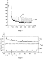
- figure 5 1 illustrates a parameter profile measured by a sensor 101 according to an exemplary embodiment of the invention.
- a measured parameter profile during the drying phases 140 of the soil layer to be dried Based on this diagram, a statement can be made when the fourth phase has been reached.
- an exponential fit 151 to the sensor in the drying phases provides information on this.
- the exponential fit 151 is in figure 5 represented by a dashed line.
- the non-dashed curve is the representation of the measured parameter value 152 without the switch-off phases of the drying device, the idle phases, which can be seen from the minimal interruptions in the parameter curve 152 .
- the y-axis of the graph is the difference in relative humidity between the outflowing air (soil moisture) and the inflowing air (ambient humidity) and the x-axis is a dwell time in minutes.
- the fit 151 has been carried out with these measured parameter values after a 16th switch-on phase of the drying device 102, resulting in a constant curve progression, ie a constant fit progression 151. This can be seen in particular from a residence time of 200 minutes, from which a constant progression of the fit 151 shown in dashed lines. This means that towards the end the slope no longer changes, from which it can be concluded that there is no further progress in drying. In the best case, this means that the drying process is over.
- FIG. 11 illustrates a further parameter profile measured by a sensor according to an exemplary embodiment of the invention.
- various measured parameter values are shown, with different points in time X1 to X7 being plotted on the x-axis and the absolute humidity in g (water) per kg (air) being plotted on the y-axis.
- the times X1 to X7 are on different days, ie X1 is day 1, X2 is day 2 and X3 is day 3 etc., so that this figure shows a course of the measured parameter over 7 days.
- the measured parameter in the soil layer of the soil structure 104 is the parameter value 162.
- the measured parameter value 163 is a further measured parameter value, such as the ambient humidity.
- the processor can thus determine the individual drying phases using the measured parameter values shown.
- the processor uses either all measured parameter values or only measured parameter values of the sensor 101 from specific time periods for the analysis. For example, the processor can select the points in time based on the status, that is to say based on the switching on and/or switching off of the drying device 102 .
- a first period of time from a point in time t1 after the drying device 102 is switched off to a point in time t2 before the drying device 102 is switched on which is present in FIG 6 corresponds to a period in which the status is set to 2.
- the processor may also use parameter values from only a second time period, which second time period extends from a time t3 after the drying device 102 is switched on to a time t4 before the drying device 102 is switched off, which is present in FIG 6 corresponds to a period in which the status is set to 1. In the 6 these time periods are only selected as examples.
- the 7 12 illustrates a plurality of measured parameter profiles according to an exemplary embodiment of the invention.
- a plurality of measured parameter values from a plurality of sensors 101 over a period of time from X1 to X5 are plotted on the x-axis and the relative humidity in percent is plotted on the y-axis.
- the status of the drying device 102 is again recorded by means of the line 171.
- the parameter value 173 is one other parameter value, such as the ambient humidity.
- the line 174 shown is the measured process air, which describes the pre-dried air which is introduced into the floor structure when using the push-pull method, for example. This in the 7
- the parameter values shown can be determined, for example, when using the push-pull method.
- All other parameter values shown in the figure comprise measured parameter values (of relative humidity) from a Plurality of sensors 101 (particularly four different sensors). From the 7 it can be seen that the parameter values measured by the four different sensors differ slightly in their course, but all show the typical characteristics that can be used to determine the individual drying phases. It can thus be seen that from X1 onwards, during a switch-off phase of the drying device 102, almost all measured parameter values are in the first drying phase, in which the relative humidity is 100%. It can also be seen that the first drying phase ends at different times for different sensors.
- the first drying phase ends halfway between X1 and X2, while for other sensors the first drying phase ends just before X2.
- the moisture return values of the switch-off phases of the drying device 102 for the individual sensors 101 can be seen from the figure.
- the excessive moisture values during the switch-on phases of the drying device 102 can also be derived from the figure.
- the course of the various parameter values of the sensors 101 also shows the effect of overdrying, which can be seen from the switch-off phases of the drying device, i.e. when the status is in the high level, at the end of the drying process, for example shortly before the point in time X5, in which the curve of the measured parameters falls again for some parameters and then rises again at time X5.
Landscapes
- Engineering & Computer Science (AREA)
- Architecture (AREA)
- Physics & Mathematics (AREA)
- Electromagnetism (AREA)
- Civil Engineering (AREA)
- Structural Engineering (AREA)
- Drying Of Solid Materials (AREA)
Priority Applications (2)
| Application Number | Priority Date | Filing Date | Title |
|---|---|---|---|
| EP21154842.5A EP4036341B1 (fr) | 2021-02-02 | 2021-02-02 | Procédé et système de séchage automatique doté d'une couche de sol humide d'une structure de sol à plusieurs couches |
| PL21154842.5T PL4036341T3 (pl) | 2021-02-02 | 2021-02-02 | Sposób i system do automatycznego suszenia wilgotnej warstwy podłogi wielowarstwowej struktury podłogowej |
Applications Claiming Priority (1)
| Application Number | Priority Date | Filing Date | Title |
|---|---|---|---|
| EP21154842.5A EP4036341B1 (fr) | 2021-02-02 | 2021-02-02 | Procédé et système de séchage automatique doté d'une couche de sol humide d'une structure de sol à plusieurs couches |
Publications (2)
| Publication Number | Publication Date |
|---|---|
| EP4036341A1 true EP4036341A1 (fr) | 2022-08-03 |
| EP4036341B1 EP4036341B1 (fr) | 2024-06-26 |
Family
ID=74550443
Family Applications (1)
| Application Number | Title | Priority Date | Filing Date |
|---|---|---|---|
| EP21154842.5A Active EP4036341B1 (fr) | 2021-02-02 | 2021-02-02 | Procédé et système de séchage automatique doté d'une couche de sol humide d'une structure de sol à plusieurs couches |
Country Status (2)
| Country | Link |
|---|---|
| EP (1) | EP4036341B1 (fr) |
| PL (1) | PL4036341T3 (fr) |
Cited By (1)
| Publication number | Priority date | Publication date | Assignee | Title |
|---|---|---|---|---|
| WO2025151912A1 (fr) * | 2024-01-15 | 2025-07-24 | 4Lab&Office Kg | Dispositif de mesure, système et procédé de surveillance à distance d'un processus de séchage |
Citations (3)
| Publication number | Priority date | Publication date | Assignee | Title |
|---|---|---|---|---|
| US20110167670A1 (en) * | 2010-01-08 | 2011-07-14 | Karcher North America, Inc. | Integrated Water Damage Restoration System, Sensors Therefor, and Method of Using Same |
| DE102012007273A1 (de) * | 2012-03-23 | 2013-09-26 | Trotec Gmbh & Co. Kg | System und Verfahren zur Trocknung von Dämmschichten von Fußböden im Unterdruckverfahren |
| DE102013226492A1 (de) * | 2013-12-18 | 2015-06-18 | Elk Fertighaus Gmbh | System zur Steuerung der Trocknungsphase von mit einer Fußbodenheizung versehenem Betonestrich |
-
2021
- 2021-02-02 PL PL21154842.5T patent/PL4036341T3/pl unknown
- 2021-02-02 EP EP21154842.5A patent/EP4036341B1/fr active Active
Patent Citations (3)
| Publication number | Priority date | Publication date | Assignee | Title |
|---|---|---|---|---|
| US20110167670A1 (en) * | 2010-01-08 | 2011-07-14 | Karcher North America, Inc. | Integrated Water Damage Restoration System, Sensors Therefor, and Method of Using Same |
| DE102012007273A1 (de) * | 2012-03-23 | 2013-09-26 | Trotec Gmbh & Co. Kg | System und Verfahren zur Trocknung von Dämmschichten von Fußböden im Unterdruckverfahren |
| DE102013226492A1 (de) * | 2013-12-18 | 2015-06-18 | Elk Fertighaus Gmbh | System zur Steuerung der Trocknungsphase von mit einer Fußbodenheizung versehenem Betonestrich |
Cited By (1)
| Publication number | Priority date | Publication date | Assignee | Title |
|---|---|---|---|---|
| WO2025151912A1 (fr) * | 2024-01-15 | 2025-07-24 | 4Lab&Office Kg | Dispositif de mesure, système et procédé de surveillance à distance d'un processus de séchage |
Also Published As
| Publication number | Publication date |
|---|---|
| EP4036341B1 (fr) | 2024-06-26 |
| PL4036341T3 (pl) | 2025-01-07 |
Similar Documents
| Publication | Publication Date | Title |
|---|---|---|
| EP2638442B1 (fr) | Système d'automatisation du bâtiment | |
| DE69625000T2 (de) | Schwingungsüberwachungsvorrichtung und Überwachungsverfahren | |
| DE112016000097T5 (de) | Sensorsystem | |
| DE202023100001U1 (de) | Intelligentes Landwirtschaftssystem für die Überwachung der landwirtschaftlichen Umgebung und die Auswahl von Pflanzen mithilfe von IoT und maschinellem Lernen | |
| EP2403991A2 (fr) | Commande de la partie sèche étendue d'une machine papier | |
| EP1173720A1 (fr) | Procede et dispositif permettant d'optimiser la gestion et la surveillance des processus dans une installation de fabrication de pates alimentaires | |
| EP4036341B1 (fr) | Procédé et système de séchage automatique doté d'une couche de sol humide d'une structure de sol à plusieurs couches | |
| EP1220412B1 (fr) | Procédé et dispositif pour la commande et le contrôle de la consommation d'énergie électrique | |
| DE3124334A1 (de) | Stallklimaanlage | |
| DE4127179A1 (de) | Verfahren zum regeln des raumklimas in einem fuer die landwirtschaft genutzten raum | |
| EP3098527A1 (fr) | Procédé de fonctionnement d'un dispositif d'aération pour une pièce et dispositif d'aération correspondant | |
| DE10106349C2 (de) | Verfahren zur Befeuchtung eines Nutzraumes in einem Brutschrank sowie Begasungs-Brutschrank | |
| EP2271920A1 (fr) | Circuit de commande pour capteur de gaz électrochimique et procédé de réglage d'un tel capteur de gaz électrochimique | |
| EP1450137B1 (fr) | Appareil de mesure | |
| DE102008061087B4 (de) | Verfahren und Vorrichtungsanordnung zur Erfassung und Auswertung von Raumklimadaten | |
| EP0901626B1 (fr) | Procede et dispositif pour la mesure de l'humidite dans les materiaux de construction | |
| EP3225928B1 (fr) | Dispositif et procédé de régulation de la température ambiante d'une pièce et bâtiment ainsi équipé | |
| WO2014140261A1 (fr) | Entrée du schéma de tuyauterie et d'instrumentation (p&id) | |
| DE3319528C2 (de) | Verfahren und Schaltungsanordnung zur Reifung und Trocknung von Wurst oder ähnlichen Lebensmitteln | |
| DE60303259T2 (de) | Adaptives Steuersystem für ein vom Anwender einstellbares Fahrzeugsystem | |
| EP2206024B1 (fr) | Procédé de contrôle de la qualité d'un circuit de réglage dans une centrale électrique | |
| DE102005007841A1 (de) | Leiterplattenkomponenten-UmgebungsfeuchtigkeitsaussetzungsÜberwachung | |
| DE20309456U1 (de) | Kastenartige Pilzkultivierungsvorrichtung | |
| EP3483513B1 (fr) | Procédé de fonctionnement d'une installation de chauffage et installation de chauffage | |
| WO2022082244A1 (fr) | Procédé d'évaluation de l'humidité relative au niveau d'une entrée de cathode d'un empilement de piles à combustible d'un système de pile à combustible |
Legal Events
| Date | Code | Title | Description |
|---|---|---|---|
| PUAI | Public reference made under article 153(3) epc to a published international application that has entered the european phase |
Free format text: ORIGINAL CODE: 0009012 |
|
| STAA | Information on the status of an ep patent application or granted ep patent |
Free format text: STATUS: THE APPLICATION HAS BEEN PUBLISHED |
|
| AK | Designated contracting states |
Kind code of ref document: A1 Designated state(s): AL AT BE BG CH CY CZ DE DK EE ES FI FR GB GR HR HU IE IS IT LI LT LU LV MC MK MT NL NO PL PT RO RS SE SI SK SM TR |
|
| STAA | Information on the status of an ep patent application or granted ep patent |
Free format text: STATUS: REQUEST FOR EXAMINATION WAS MADE |
|
| 17P | Request for examination filed |
Effective date: 20221020 |
|
| RBV | Designated contracting states (corrected) |
Designated state(s): AL AT BE BG CH CY CZ DE DK EE ES FI FR GB GR HR HU IE IS IT LI LT LU LV MC MK MT NL NO PL PT RO RS SE SI SK SM TR |
|
| P01 | Opt-out of the competence of the unified patent court (upc) registered |
Effective date: 20230503 |
|
| GRAP | Despatch of communication of intention to grant a patent |
Free format text: ORIGINAL CODE: EPIDOSNIGR1 |
|
| STAA | Information on the status of an ep patent application or granted ep patent |
Free format text: STATUS: GRANT OF PATENT IS INTENDED |
|
| INTG | Intention to grant announced |
Effective date: 20240219 |
|
| GRAJ | Information related to disapproval of communication of intention to grant by the applicant or resumption of examination proceedings by the epo deleted |
Free format text: ORIGINAL CODE: EPIDOSDIGR1 |
|
| STAA | Information on the status of an ep patent application or granted ep patent |
Free format text: STATUS: REQUEST FOR EXAMINATION WAS MADE |
|
| GRAP | Despatch of communication of intention to grant a patent |
Free format text: ORIGINAL CODE: EPIDOSNIGR1 |
|
| STAA | Information on the status of an ep patent application or granted ep patent |
Free format text: STATUS: GRANT OF PATENT IS INTENDED |
|
| INTC | Intention to grant announced (deleted) | ||
| GRAS | Grant fee paid |
Free format text: ORIGINAL CODE: EPIDOSNIGR3 |
|
| INTG | Intention to grant announced |
Effective date: 20240424 |
|
| GRAA | (expected) grant |
Free format text: ORIGINAL CODE: 0009210 |
|
| STAA | Information on the status of an ep patent application or granted ep patent |
Free format text: STATUS: THE PATENT HAS BEEN GRANTED |
|
| AK | Designated contracting states |
Kind code of ref document: B1 Designated state(s): AL AT BE BG CH CY CZ DE DK EE ES FI FR GB GR HR HU IE IS IT LI LT LU LV MC MK MT NL NO PL PT RO RS SE SI SK SM TR |
|
| REG | Reference to a national code |
Ref country code: GB Ref legal event code: FG4D Free format text: NOT ENGLISH |
|
| REG | Reference to a national code |
Ref country code: CH Ref legal event code: EP |
|
| REG | Reference to a national code |
Ref country code: DE Ref legal event code: R096 Ref document number: 502021004078 Country of ref document: DE |
|
| REG | Reference to a national code |
Ref country code: SE Ref legal event code: TRGR |
|
| REG | Reference to a national code |
Ref country code: NL Ref legal event code: FP |
|
| PG25 | Lapsed in a contracting state [announced via postgrant information from national office to epo] |
Ref country code: BG Free format text: LAPSE BECAUSE OF FAILURE TO SUBMIT A TRANSLATION OF THE DESCRIPTION OR TO PAY THE FEE WITHIN THE PRESCRIBED TIME-LIMIT Effective date: 20240626 |
|
| PG25 | Lapsed in a contracting state [announced via postgrant information from national office to epo] |
Ref country code: HR Free format text: LAPSE BECAUSE OF FAILURE TO SUBMIT A TRANSLATION OF THE DESCRIPTION OR TO PAY THE FEE WITHIN THE PRESCRIBED TIME-LIMIT Effective date: 20240626 Ref country code: FI Free format text: LAPSE BECAUSE OF FAILURE TO SUBMIT A TRANSLATION OF THE DESCRIPTION OR TO PAY THE FEE WITHIN THE PRESCRIBED TIME-LIMIT Effective date: 20240626 |
|
| REG | Reference to a national code |
Ref country code: LT Ref legal event code: MG9D |
|
| PG25 | Lapsed in a contracting state [announced via postgrant information from national office to epo] |
Ref country code: GR Free format text: LAPSE BECAUSE OF FAILURE TO SUBMIT A TRANSLATION OF THE DESCRIPTION OR TO PAY THE FEE WITHIN THE PRESCRIBED TIME-LIMIT Effective date: 20240927 |
|
| PG25 | Lapsed in a contracting state [announced via postgrant information from national office to epo] |
Ref country code: LV Free format text: LAPSE BECAUSE OF FAILURE TO SUBMIT A TRANSLATION OF THE DESCRIPTION OR TO PAY THE FEE WITHIN THE PRESCRIBED TIME-LIMIT Effective date: 20240626 |
|
| PG25 | Lapsed in a contracting state [announced via postgrant information from national office to epo] |
Ref country code: NO Free format text: LAPSE BECAUSE OF FAILURE TO SUBMIT A TRANSLATION OF THE DESCRIPTION OR TO PAY THE FEE WITHIN THE PRESCRIBED TIME-LIMIT Effective date: 20240926 Ref country code: LV Free format text: LAPSE BECAUSE OF FAILURE TO SUBMIT A TRANSLATION OF THE DESCRIPTION OR TO PAY THE FEE WITHIN THE PRESCRIBED TIME-LIMIT Effective date: 20240626 Ref country code: HR Free format text: LAPSE BECAUSE OF FAILURE TO SUBMIT A TRANSLATION OF THE DESCRIPTION OR TO PAY THE FEE WITHIN THE PRESCRIBED TIME-LIMIT Effective date: 20240626 Ref country code: GR Free format text: LAPSE BECAUSE OF FAILURE TO SUBMIT A TRANSLATION OF THE DESCRIPTION OR TO PAY THE FEE WITHIN THE PRESCRIBED TIME-LIMIT Effective date: 20240927 Ref country code: FI Free format text: LAPSE BECAUSE OF FAILURE TO SUBMIT A TRANSLATION OF THE DESCRIPTION OR TO PAY THE FEE WITHIN THE PRESCRIBED TIME-LIMIT Effective date: 20240626 Ref country code: BG Free format text: LAPSE BECAUSE OF FAILURE TO SUBMIT A TRANSLATION OF THE DESCRIPTION OR TO PAY THE FEE WITHIN THE PRESCRIBED TIME-LIMIT Effective date: 20240626 Ref country code: RS Free format text: LAPSE BECAUSE OF FAILURE TO SUBMIT A TRANSLATION OF THE DESCRIPTION OR TO PAY THE FEE WITHIN THE PRESCRIBED TIME-LIMIT Effective date: 20240926 |
|
| PG25 | Lapsed in a contracting state [announced via postgrant information from national office to epo] |
Ref country code: PT Free format text: LAPSE BECAUSE OF FAILURE TO SUBMIT A TRANSLATION OF THE DESCRIPTION OR TO PAY THE FEE WITHIN THE PRESCRIBED TIME-LIMIT Effective date: 20241028 |
|
| PG25 | Lapsed in a contracting state [announced via postgrant information from national office to epo] |
Ref country code: PT Free format text: LAPSE BECAUSE OF FAILURE TO SUBMIT A TRANSLATION OF THE DESCRIPTION OR TO PAY THE FEE WITHIN THE PRESCRIBED TIME-LIMIT Effective date: 20241028 |
|
| PG25 | Lapsed in a contracting state [announced via postgrant information from national office to epo] |
Ref country code: EE Free format text: LAPSE BECAUSE OF FAILURE TO SUBMIT A TRANSLATION OF THE DESCRIPTION OR TO PAY THE FEE WITHIN THE PRESCRIBED TIME-LIMIT Effective date: 20240626 |
|
| PG25 | Lapsed in a contracting state [announced via postgrant information from national office to epo] |
Ref country code: IS Free format text: LAPSE BECAUSE OF FAILURE TO SUBMIT A TRANSLATION OF THE DESCRIPTION OR TO PAY THE FEE WITHIN THE PRESCRIBED TIME-LIMIT Effective date: 20241026 |
|
| PG25 | Lapsed in a contracting state [announced via postgrant information from national office to epo] |
Ref country code: CZ Free format text: LAPSE BECAUSE OF FAILURE TO SUBMIT A TRANSLATION OF THE DESCRIPTION OR TO PAY THE FEE WITHIN THE PRESCRIBED TIME-LIMIT Effective date: 20240626 |
|
| PG25 | Lapsed in a contracting state [announced via postgrant information from national office to epo] |
Ref country code: SK Free format text: LAPSE BECAUSE OF FAILURE TO SUBMIT A TRANSLATION OF THE DESCRIPTION OR TO PAY THE FEE WITHIN THE PRESCRIBED TIME-LIMIT Effective date: 20240626 Ref country code: RO Free format text: LAPSE BECAUSE OF FAILURE TO SUBMIT A TRANSLATION OF THE DESCRIPTION OR TO PAY THE FEE WITHIN THE PRESCRIBED TIME-LIMIT Effective date: 20240626 |
|
| PG25 | Lapsed in a contracting state [announced via postgrant information from national office to epo] |
Ref country code: SM Free format text: LAPSE BECAUSE OF FAILURE TO SUBMIT A TRANSLATION OF THE DESCRIPTION OR TO PAY THE FEE WITHIN THE PRESCRIBED TIME-LIMIT Effective date: 20240626 Ref country code: ES Free format text: LAPSE BECAUSE OF FAILURE TO SUBMIT A TRANSLATION OF THE DESCRIPTION OR TO PAY THE FEE WITHIN THE PRESCRIBED TIME-LIMIT Effective date: 20240626 |
|
| PG25 | Lapsed in a contracting state [announced via postgrant information from national office to epo] |
Ref country code: SM Free format text: LAPSE BECAUSE OF FAILURE TO SUBMIT A TRANSLATION OF THE DESCRIPTION OR TO PAY THE FEE WITHIN THE PRESCRIBED TIME-LIMIT Effective date: 20240626 Ref country code: SK Free format text: LAPSE BECAUSE OF FAILURE TO SUBMIT A TRANSLATION OF THE DESCRIPTION OR TO PAY THE FEE WITHIN THE PRESCRIBED TIME-LIMIT Effective date: 20240626 Ref country code: RO Free format text: LAPSE BECAUSE OF FAILURE TO SUBMIT A TRANSLATION OF THE DESCRIPTION OR TO PAY THE FEE WITHIN THE PRESCRIBED TIME-LIMIT Effective date: 20240626 Ref country code: IS Free format text: LAPSE BECAUSE OF FAILURE TO SUBMIT A TRANSLATION OF THE DESCRIPTION OR TO PAY THE FEE WITHIN THE PRESCRIBED TIME-LIMIT Effective date: 20241026 Ref country code: ES Free format text: LAPSE BECAUSE OF FAILURE TO SUBMIT A TRANSLATION OF THE DESCRIPTION OR TO PAY THE FEE WITHIN THE PRESCRIBED TIME-LIMIT Effective date: 20240626 Ref country code: EE Free format text: LAPSE BECAUSE OF FAILURE TO SUBMIT A TRANSLATION OF THE DESCRIPTION OR TO PAY THE FEE WITHIN THE PRESCRIBED TIME-LIMIT Effective date: 20240626 Ref country code: CZ Free format text: LAPSE BECAUSE OF FAILURE TO SUBMIT A TRANSLATION OF THE DESCRIPTION OR TO PAY THE FEE WITHIN THE PRESCRIBED TIME-LIMIT Effective date: 20240626 |
|
| REG | Reference to a national code |
Ref country code: DE Ref legal event code: R097 Ref document number: 502021004078 Country of ref document: DE |
|
| PG25 | Lapsed in a contracting state [announced via postgrant information from national office to epo] |
Ref country code: DK Free format text: LAPSE BECAUSE OF FAILURE TO SUBMIT A TRANSLATION OF THE DESCRIPTION OR TO PAY THE FEE WITHIN THE PRESCRIBED TIME-LIMIT Effective date: 20240626 |
|
| PLBE | No opposition filed within time limit |
Free format text: ORIGINAL CODE: 0009261 |
|
| STAA | Information on the status of an ep patent application or granted ep patent |
Free format text: STATUS: NO OPPOSITION FILED WITHIN TIME LIMIT |
|
| 26N | No opposition filed |
Effective date: 20250327 |
|
| PG25 | Lapsed in a contracting state [announced via postgrant information from national office to epo] |
Ref country code: MC Free format text: LAPSE BECAUSE OF FAILURE TO SUBMIT A TRANSLATION OF THE DESCRIPTION OR TO PAY THE FEE WITHIN THE PRESCRIBED TIME-LIMIT Effective date: 20240626 |
|
| PG25 | Lapsed in a contracting state [announced via postgrant information from national office to epo] |
Ref country code: LU Free format text: LAPSE BECAUSE OF NON-PAYMENT OF DUE FEES Effective date: 20250202 |
|
| REG | Reference to a national code |
Ref country code: BE Ref legal event code: MM Effective date: 20250228 |
|
| PG25 | Lapsed in a contracting state [announced via postgrant information from national office to epo] |
Ref country code: BE Free format text: LAPSE BECAUSE OF NON-PAYMENT OF DUE FEES Effective date: 20250228 |
|
| PG25 | Lapsed in a contracting state [announced via postgrant information from national office to epo] |
Ref country code: IE Free format text: LAPSE BECAUSE OF NON-PAYMENT OF DUE FEES Effective date: 20250202 |
|
| REG | Reference to a national code |
Ref country code: CH Ref legal event code: U11 Free format text: ST27 STATUS EVENT CODE: U-0-0-U10-U11 (AS PROVIDED BY THE NATIONAL OFFICE) Effective date: 20260301 |
|
| PGFP | Annual fee paid to national office [announced via postgrant information from national office to epo] |
Ref country code: NL Payment date: 20260218 Year of fee payment: 6 |
|
| PGFP | Annual fee paid to national office [announced via postgrant information from national office to epo] |
Ref country code: SE Payment date: 20260218 Year of fee payment: 6 |
|
| PGFP | Annual fee paid to national office [announced via postgrant information from national office to epo] |
Ref country code: GB Payment date: 20260219 Year of fee payment: 6 |
|
| PGFP | Annual fee paid to national office [announced via postgrant information from national office to epo] |
Ref country code: DE Payment date: 20260225 Year of fee payment: 6 |
|
| PGFP | Annual fee paid to national office [announced via postgrant information from national office to epo] |
Ref country code: AT Payment date: 20260216 Year of fee payment: 6 |
|
| PGFP | Annual fee paid to national office [announced via postgrant information from national office to epo] |
Ref country code: IT Payment date: 20260227 Year of fee payment: 6 |
|
| PGFP | Annual fee paid to national office [announced via postgrant information from national office to epo] |
Ref country code: FR Payment date: 20260223 Year of fee payment: 6 |
|
| PGFP | Annual fee paid to national office [announced via postgrant information from national office to epo] |
Ref country code: CH Payment date: 20260301 Year of fee payment: 6 |
|
| PGFP | Annual fee paid to national office [announced via postgrant information from national office to epo] |
Ref country code: PL Payment date: 20260126 Year of fee payment: 6 |