EP4037970B1 - Fixation de palier de couple de plateau inférieur - Google Patents
Fixation de palier de couple de plateau inférieur Download PDFInfo
- Publication number
- EP4037970B1 EP4037970B1 EP19790955.9A EP19790955A EP4037970B1 EP 4037970 B1 EP4037970 B1 EP 4037970B1 EP 19790955 A EP19790955 A EP 19790955A EP 4037970 B1 EP4037970 B1 EP 4037970B1
- Authority
- EP
- European Patent Office
- Prior art keywords
- seat
- elongated body
- seat bottom
- torque bearing
- attachment
- Prior art date
- Legal status (The legal status is an assumption and is not a legal conclusion. Google has not performed a legal analysis and makes no representation as to the accuracy of the status listed.)
- Active
Links
Images


Classifications
-
- B—PERFORMING OPERATIONS; TRANSPORTING
- B64—AIRCRAFT; AVIATION; COSMONAUTICS
- B64D—EQUIPMENT FOR FITTING IN OR TO AIRCRAFT; FLIGHT SUITS; PARACHUTES; ARRANGEMENT OR MOUNTING OF POWER PLANTS OR PROPULSION TRANSMISSIONS IN AIRCRAFT
- B64D11/00—Passenger or crew accommodation; Flight-deck installations not otherwise provided for
- B64D11/06—Arrangements of seats, or adaptations or details specially adapted for aircraft seats
- B64D11/0639—Arrangements of seats, or adaptations or details specially adapted for aircraft seats with features for adjustment or converting of seats
- B64D11/064—Adjustable inclination or position of seats
-
- B—PERFORMING OPERATIONS; TRANSPORTING
- B60—VEHICLES IN GENERAL
- B60N—SEATS SPECIALLY ADAPTED FOR VEHICLES; VEHICLE PASSENGER ACCOMMODATION NOT OTHERWISE PROVIDED FOR
- B60N2/00—Seats specially adapted for vehicles; Arrangement or mounting of seats in vehicles
- B60N2/24—Seats specially adapted for vehicles; Arrangement or mounting of seats in vehicles for particular purposes or particular vehicles
- B60N2/242—Bus seats
-
- B—PERFORMING OPERATIONS; TRANSPORTING
- B60—VEHICLES IN GENERAL
- B60N—SEATS SPECIALLY ADAPTED FOR VEHICLES; VEHICLE PASSENGER ACCOMMODATION NOT OTHERWISE PROVIDED FOR
- B60N2/00—Seats specially adapted for vehicles; Arrangement or mounting of seats in vehicles
- B60N2/02—Seats specially adapted for vehicles; Arrangement or mounting of seats in vehicles the seat or part thereof being movable, e.g. adjustable
- B60N2/04—Seats specially adapted for vehicles; Arrangement or mounting of seats in vehicles the seat or part thereof being movable, e.g. adjustable the whole seat being movable
- B60N2/12—Seats specially adapted for vehicles; Arrangement or mounting of seats in vehicles the seat or part thereof being movable, e.g. adjustable the whole seat being movable slidable and tiltable
-
- B—PERFORMING OPERATIONS; TRANSPORTING
- B60—VEHICLES IN GENERAL
- B60N—SEATS SPECIALLY ADAPTED FOR VEHICLES; VEHICLE PASSENGER ACCOMMODATION NOT OTHERWISE PROVIDED FOR
- B60N2/00—Seats specially adapted for vehicles; Arrangement or mounting of seats in vehicles
- B60N2/02—Seats specially adapted for vehicles; Arrangement or mounting of seats in vehicles the seat or part thereof being movable, e.g. adjustable
- B60N2/20—Seats specially adapted for vehicles; Arrangement or mounting of seats in vehicles the seat or part thereof being movable, e.g. adjustable the back-rest being tiltable, e.g. to permit easy access
-
- B—PERFORMING OPERATIONS; TRANSPORTING
- B60—VEHICLES IN GENERAL
- B60N—SEATS SPECIALLY ADAPTED FOR VEHICLES; VEHICLE PASSENGER ACCOMMODATION NOT OTHERWISE PROVIDED FOR
- B60N2/00—Seats specially adapted for vehicles; Arrangement or mounting of seats in vehicles
- B60N2/02—Seats specially adapted for vehicles; Arrangement or mounting of seats in vehicles the seat or part thereof being movable, e.g. adjustable
- B60N2/22—Seats specially adapted for vehicles; Arrangement or mounting of seats in vehicles the seat or part thereof being movable, e.g. adjustable the back-rest being adjustable
- B60N2/2209—Seats specially adapted for vehicles; Arrangement or mounting of seats in vehicles the seat or part thereof being movable, e.g. adjustable the back-rest being adjustable by longitudinal displacement of the cushion, e.g. back-rest hinged on the bottom to the cushion and linked on the top to the vehicle frame
-
- B—PERFORMING OPERATIONS; TRANSPORTING
- B64—AIRCRAFT; AVIATION; COSMONAUTICS
- B64D—EQUIPMENT FOR FITTING IN OR TO AIRCRAFT; FLIGHT SUITS; PARACHUTES; ARRANGEMENT OR MOUNTING OF POWER PLANTS OR PROPULSION TRANSMISSIONS IN AIRCRAFT
- B64D11/00—Passenger or crew accommodation; Flight-deck installations not otherwise provided for
- B64D11/06—Arrangements of seats, or adaptations or details specially adapted for aircraft seats
- B64D11/0648—Lower frame constructions
Definitions
- the field of the invention relates to passenger seats.
- seats are designed to meet the needs of passenger safety and comfort, while accounting for strict limitations on weight and space.
- passenger seats are designed with rigid supportive structures to meet safety criteria, typically including rigid seat pans that provide a supportive seating surface for passengers.
- Modern seat assemblies are becoming more complex with time and require increased strength to incorporate improved safety features and articulation; although the driving concerns of passenger support, cost, and weight remain the same. To that end, improved structural performance solutions in seat assemblies, including seat pans, are needed.
- the document US8439435 describes a passenger seat comprising a scat pan assembly, a seat back pivotally coupled to the aft end of the seat pan assembly, and a lumbar mechanism coupled to the seat back and the seat pan assembly.
- the seat pan assembly comprises a reclining mechanism and a tilting mechanism.
- the reclining mechanism is configured to adjust a forward position of the seat pan assembly and the rotation of the seat back between upright and reclining positions.
- the document US10053219 describes a displacement system for a seat, in particular an airplane seat, comprising a sitting portion, a backrest and a legrest.
- the displacement system comprises a support structure for the support of the seat, a sitting portion structure for the support of the sitting portion.
- the sitting portion structure is connected to the support structure and comprises a sitting portion surface lying at least on a first plane, and displacement means acting at least on the sitting portion structure in such a way that said displacement system passes between a sitting configuration and a cradle configuration and vice versa.
- a torque bearing attachment for a passenger seat includes an elongated body formed of a hollow conduit, a flat upper surface, and a concave lower surface.
- the torque bearing attachment includes a first bearing element configured for connecting the torque bearing attachment with a passenger seat frame and connected with the elongated body at a first end of the elongated body, and a second bearing element configured for connecting the torque bearing attachment with the passenger seat frame and connected with the elongated body at a second end of the elongated body opposite the first end.
- the torque bearing attachment further includes one or more connecting features positioned at a forward edge of the elongated body between the first end and second end, such as a channel, configured to receive an aft end of a seat bottom panel.
- a passenger seat can include a seat frame connected with a seat bottom assembly formed by connecting a seat bottom panel with any suitable embodiment of a torque bearing attachment as described herein.
- the described embodiments of the invention provide for a torque bearing assembly for the seat bottom assemblies of passenger seats, in the form of a torque bearing attachment that mates with a seat bottom panel to form an aft portion of the seat bottom assembly.
- the torque bearing assemblies can improve the strength and resilience of the seat bottom assemblies by adding structural strength to the back end of a seat bottom pan, including the portions of the seat bottom pan where load-bearing elements or bearings mate with the seat frame and/or with the seat back, and where the seat bottom assemblies may be vulnerable to stresses caused by other adjacent passengers (e.g., when used as a step).
- Various embodiments of the torque bearing assemblies may be formed to mate interchangeably with different seat bottom panels, and may differ in shape in order to accommodate seats that require differing amounts of clearance underneath the seat bottom assembly. While the torque bearing assemblies are discussed for use with aircraft seats, they are by no means so limited. Rather, embodiments of the torque bearing assemblies may be used in passenger seats or other seats of any type or otherwise as desired.
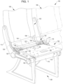
- a passenger seat assembly 100 can include one or more passenger seats 102.
- Each passenger seat 102 includes a seat bottom assembly 104 and a seat back assembly 106 supported by a seat frame 108 that is connectable with structural elements of a passenger cabin.
- the seat frame 108 can include a set of supportive structural tubes 110 (or comparable elements) that can support the load-bearing parts of the passenger seat 102, e.g., the seat bottom assembly 104, spreaders 112, and by extension the seat back assembly 106.
- Specific attachment means may vary, but in general, the seat bottom assembly 104 can be supported by connection with the structural tubes 110 and/or the spreaders 112.
- the seat bottom assembly 104 can include a seat bottom panel 120 that forms much or most of the supportive area thereof.
- the seat bottom panel 120 is connected to the torque bearing attachment 122 by inserting an aft end of the seat bottom panel into a channel 128 in a forward edge of the torque bearing assembly, where it can be fixed in place by, e.g., connectors (such as bolts, screws, or the like), adhesive, or any other suitable connecting means.
- the torque bearing attachment 122 includes an elongated body 130 that has a hollow, truss-like cross section, an aft platform 132 formed by an extension of the elongated body, and one or more reinforced bearing assemblies 150 that are attached to the elongated body 130.
- the reinforced bearing assemblies 150 can include attachment features for connecting the seat bottom assembly 104 with the frame 108.
- the underside of the torque bearing attachment 122, opposite the aft platform 132, can be a substantially concave surface 134 that may be curved or formed of flat panels meeting at an angle so that the concave surface provides clearance over other structural features of the passenger seat 102 such as the structural tubes 110.
- the seat bottom assembly 104 is movably attached with the frame 108 by way of a pair of aft bearing elements 124 connected to the reinforced bearing assemblies 150.
- the aft bearing elements 124 are connected with a pair of aft support assemblies 114 that contain arcuate tracks 116 into which the aft bearings are configured to roll forward and aft.
- the seat bottom assembly 104 can also be connected near a forward end thereof by a set of tracked ramps 126 that slidingly mate with a set of bearing elements 118 mounted to the structural tubes 110.
- This combination of movable attachment elements can permit the seat bottom assembly 104 as a whole to slide forward and aft with respect to the frame 108.
- the sliding motion may also permit the seat bottom assembly 104 to tilt while actuating forward and aft, e.g., in a cradling motion.
- the concave surface 134 underneath the body 130 of the torque bearing attachment 122 may be shaped to provide clearance over the structural tubes 110 as the seat bottom assembly 104 articulates. This clearance may be advantageous when, for example, components of an existing non-articulating passenger seat are removed and replaced with an articulating seat bottom assembly that might not otherwise clear parts of the frame 108, structural tubes 110, or spreaders 112.
- the seat bottom assembly 104 can be constrained to horizontal motion, or may be fixed in place with respect to the frame 108.
- alternative attachment points for the aft support assemblies 114 and forward bearing elements 118 can be used, e.g., by attachment of both or either assembly to the structural tubes 110, to the spreaders 112, or in some embodiments, even to the frame 108.
- the elongate body 130 of the torque bearing attachment 122 may include a central portion formed of a truss-like cross-section having, e.g., a triangular or trapezoidal shape that is lightweight and resistant against bending.
- the reinforced bearing assemblies 150 may be attached to the ends of the elongate body 130 where the truss-like structure maximizes the strength of the torque bearing attachment 122, in order to prevent bending of the seat bottom assembly 104 during use.
- the torque bearing attachment 122 may be formed of materials including but not limited to aluminum, stainless steel, aramid fibers, polycarbonate, polypropylene, other metallic materials, composite materials, or other similar materials, in accordance with various embodiments.
- the torque bearing attachment 122 is formed of a strong and lightweight material that is suitable for manufacture primarily by extrusion (e.g., extrusion of the body 130 prior to supplemental machining or attachment of additional elements).
- Suitable extrusion-formable materials suitable for use in the torque bearing attachment 122 body 130 may include most metals (e.g., aluminum and aluminum alloys, magnesium and magnesium alloys, steel, etc.) and various high-strength polymers.
- the seat bottom panel 120 may be formed of any of the materials described above.
- the seat bottom panel 120 can be a composite (e.g. a polymer/polymer composite, or metal/polymer composite), and in particular may be a sandwich panel composite having a structured lightweight core and relatively thin face sheets (e.g., 0.25 cm to 2.5 cm) formed of stiff polymer, metal, and/or composite sheets.
- the seat bottom panel 120 is preferably from 0.5 to 1.5 cm thick.
- FIG. 2A is a perspective view showing the torque bearing attachment 122 of the seat bottom assembly 104 of FIG. 1 disconnected from the seat bottom panel 120.
- the seat bottom panel 120 can be connected with the torque bearing attachment 122 by sliding an aft end 140 of the seat bottom panel 120 into a channel 128 in a forward end of the torque bearing attachment 122.
- the channel 128 has a depth 146 that preferably matches or exceeds an insertion length 142 of the seat bottom panel 120.
- the insertion length 142 may vary from about 0.635 cm to 6.35 cm, or preferably from 1 cm to 5 cm.
- the seat bottom panel 120 can be secured in the channel 128 by way of one or multiple connectors 144 (e.g.
- the interaction of the seat bottom panel 120 with the channel 128 can provide sufficient torsional stiffness to the connection for supporting a passenger, but in some embodiments, additional reinforcing elements may be used.
- the side ends of the torque bearing attachment 122 can include most of the hardware for connection of the seat bottom assembly 104 with a passenger seat frame and seat back, including, e.g., the aft bearing elements 124 and attachment elements 136 for connecting the seat bottom assembly with a reclinable seat back.
- These structural features can be connected with the torque bearing attachment 122 adjacent a truss-like conduit 148 that may run a length of the attachment, and that provides much more structural rigidity to the torque bearing attachment than would be provided by a flat part, or by the seat bottom panel 120.
- FIG. 2B is a perspective view showing the torque bearing attachment 122 of FIG. 2A connected with the seat bottom panel 120 in greater detail, together forming the seat bottom assembly 104.
- the shape of the torque bearing attachment 122 is selected so that the seat bottom assembly 104, when complete and when attached to a passenger seat frame, is able to clear elements of the passenger seat frame when static or, in the case of actuating seat bottom assemblies, when the seat bottom assembly is actuated by a passenger.
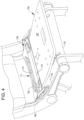
- FIG. 3A and FIG. 3B illustrate the clearance by a seat bottom assembly 104 of such structural elements in the course of an articulating / reclining motion.
- the seat bottom panel 120 and torque bearing attachment 122 of the seat bottom assembly 104 are above and clear of structural features such as, but not limited to, the structural tubes 110.
- a recline action as shown in FIG.
- the seat back assembly 106 reclines backward while the seat bottom assembly 104 articulates forward and tilts aft. This articulating motion would impinge on the structural tube 110, but for the concave surface 134 underneath the torque bearing attachment 122 moving along and clearing the structural tube.
- the specific shape of the concave surface 134 can be varied according to the exact dimensions of the seat to which the torque bearing attachment 122 is intended, and the amount of clearance desired.
- the torque bearing attachments 122 described herein provide a modular solution for retrofitting seat bottom assemblies to existing seat frames with limited clearance, and for improved strength of the seat bottom assemblies at their connection points to the seat frames (e.g., at their bearing elements).
- the torque bearing attachments 122 also provide greater resilience against local stresses than existing seat bottom designs.
- seat bottom assemblies 104 may be subjected to localized stresses at certain locations, such as along an aft platform 132. Some causes of point stress on a seat bottom assembly 104 may include dropped objects, kneeling or standing on a seat bottom from behind the seat.
- FIG. 4 illustrates an example of a point force 131 exerted on the aft platform 132 of the torque bearing attachment 122, and an exaggerated strain response 133 shows how stresses on the seat bottom assembly 104 are absorbed by the torque bearing attachment 122 without being translated into the seat bottom panel 120.
- the truss-like conduit 148 of the body 130 of the torque bearing attachment 122 is resilient against bending.
- the aft platform 132 may be able to reversibly bend in response to local stress, thus absorbing force with minimal risk of failure.
- the elongate body 130 of the torque bearing attachment 122 can be formed in a variety of shapes configured to tune the strength, weight, and clearance (i.e. the shape of the concave surface 134) underneath the assembly.
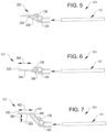
- Several examples of alternative torque bearing assemblies are illustrated in FIGS. 5-7 , which are interchangeably attachable with the seat bottom panel 120.
- the body 130 of the torque bearing attachment 122 is an extrudable shape that can be cheaply produced from a formable or ductile medium and cut to any suitable desired length; but in some embodiments, the body 130 can be formed by casting or molding, formed as a composite, or machined.
- FIG. 5 is side section view showing a second embodiment of a torque bearing attachment 222 with a curved profile connected with a seat bottom panel 120 to from seat bottom assembly 204.
- the torque bearing attachment 222 includes a hollow truss-like conduit 248 with at least one curved wall coinciding with the curved concave surface 234 that is shaped to clear structural elements of a passenger seat such as the passenger seat 102 shown in FIG. 1 .
- a curved concave surface 234 can be fine-tuned based on the path by which the seat bottom assembly 204 actuates.
- FIG. 6 is a side section view showing a third embodiment of a torque bearing attachment 322 with an flattened profile connected with a seat bottom panel 120 to form seat bottom assembly 304.
- the hollow truss-like conduit 348 can be reduced in size and/or changed in shape in order to minimize the rise of the aft portion 332 of the attachment.
- the concave surface 334 can vary in shape by changing the size of the hollow truss-like conduit 348, and can have any suitable depth 362 depending on the required depth of the seat bottom assembly 304.
- FIG. 7 is a side section view showing a fourth embodiment of a torque bearing attachment 422 with an elevated profile connected with a seat bottom panel 120 to form seat bottom assembly 404.
- the hollow truss-like conduit 448 can be increased in length, dimension, or slope in shape in order to vary the amount of rise 460 of the aft portion 432 of the attachment, as well as the depth 462 thereof.
- the concave surface 434 can vary in shape by changing the size and shape of the hollow truss-like conduit 448.
- a torque bearing attachment can have any suitable rise 460 as needed based on the shape desired for the seat bottom assembly, or the clearance required beneath the seat bottom assembly.
- the rise 460 of the aft portion 432 of the torque bearing attachment 422 can vary from between 0 cm and 5 cm, though other dimensions are possible within the scope of this disclosure.
- the sloped portion 449 can have a length from 0 cm (no rise, e.g. FIG. 6 ) up to 7.5 cm.
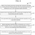
- FIG. 8 illustrates a first process 800 for assembling a seat bottom assembly with a torque bearing attachment and seat bottom panel, not according to the claims.
- a torque bearing attachment of a passenger seat bottom assembly can be attached with a passenger seat frame by inserting a first set of bearing elements of the torque bearing seat bottom assembly into one or more receiving aft support assemblies.
- aft end of a seat bottom panel can then be inserted into a channel along a forward end of the torque bearing attachment.
- the assembly of the seat bottom panel can precede assembly of the torque bearing attachment with the seat frame.
- the seat bottom assembly can be moved forward or aft by sliding the bearing elements along the one or more aft support assemblies until one or more forward support assemblies are aligned with one or more respective forward bearing elements.
- the seat bottom assembly can then be further attached with the frame by mating the forward support assemblies with the forward bearing elements, which can include, e.g., inserting bearing elements into openings in a ramp or track.
- the seat bottom assembly can then be secured in place with respect to the frame by, e.g., pinning the bearing elements in place with respect to the forward support assemblies or moving the seat bottom assembly to a position or range of positions where backout of the bearing elements from the respective support assemblies is prevented.
- the process 800 may be automated and performed mechanically under the control of one or more computer systems configured with executable instructions and implemented as code (e.g., executable instructions, one or more computer programs, or one or more applications) executing collectively on one or more processors, by hardware or combinations thereof.
- the code may be stored on a computer-readable storage medium, for example, in the form of a computer program comprising a plurality of instructions executable by one or more processors.
- the computer-readable storage medium may be non-transitory. In some embodiments, aspects of process 800 may be performed manually.
Landscapes
- Engineering & Computer Science (AREA)
- Aviation & Aerospace Engineering (AREA)
- Transportation (AREA)
- Mechanical Engineering (AREA)
- Seats For Vehicles (AREA)
Claims (16)
- Fixation de palier de couple (122) destinée à un siège de passager, la fixation comprenant :un corps allongé (130) comprenant une surface supérieure plate ;un premier élément de palier (124) configuré pour relier la fixation de palier de couple (122) à un cadre de siège de passager (108) et relié au corps allongé (130) à une première extrémité du corps allongé (130) ;un deuxième élément de palier (124) configuré pour relier la fixation de palier de couple (122) au cadre de siège de passager (108) et relié au corps allongé (130) à une deuxième extrémité du corps allongé (130) opposée à la première extrémité ;et
caractérisé en ce que le corps allongé (130) comprend un conduit creux et une surface inférieure concave (134) et en ce que la fixation de palier de couple (122) comprend en outre :
un ou plusieurs éléments de liaison (128, 144) positionnés au niveau d'un bord avant du corps allongé entre la première extrémité et la deuxième extrémité, et configurés pour recevoir une extrémité arrière d'un panneau de siège inférieur (120). - Fixation de palier de couple selon la revendication 1, caractérisée en ce que le corps allongé (130) comprend en outre une surface supérieure inclinée allant depuis le bord avant à la surface supérieure plate, et la surface supérieure plate se terminant au niveau d'un bord arrière du corps allongé (130).
- Fixation de palier de couple selon la revendication 1 ou la revendication 2, caractérisée en ce que le corps allongé (130) comprend une construction en treillis comprenant au moins trois panneaux allongés joints ou coextrudés solidairement et configurés pour résister à la flexion.
- Fixation de palier de couple selon l'une quelconque des revendications précédentes, caractérisée en ce que le corps allongé (130) comprend un élément structurel extrudé relié aux premier et deuxième éléments de palier (124).
- Fixation de palier de couple selon l'une quelconque des revendications précédentes, caractérisée en ce que le bord avant du corps allongé (130) comprend un canal (128) dimensionné pour recevoir l'extrémité arrière du panneau de siège inférieur (120) à une profondeur non nulle.
- Fixation de palier de couple selon la revendication 5, caractérisée en ce que la profondeur non nulle est de préférence dans une plage allant de 0,635 cm à 6,35 cm.
- Fixation de palier de couple selon l'une quelconque des revendications précédentes, caractérisée en ce que :le premier élément de palier (124) comprend un premier palier configuré pour s'accoupler de manière mobile à un premier élément de réception du cadre de siège de passager (108) ; etle deuxième élément de palier (124) comprend un deuxième palier configuré pour s'accoupler de manière mobile à un deuxième élément de réception du cadre de siège de passager (108) .
- Fixation de palier de couple selon l'une quelconque des revendications 1 à 6, caractérisée en ce que :le premier élément de palier (124) comprend un premier rouleau configuré pour être reçu dans un premier guide de rouleau (116) relié au cadre de siège de passager (108) ; etle deuxième élément de palier (124) comprend un deuxième rouleau configuré pour être reçu dans un deuxième guide de rouleau (116) relié au cadre de siège de passager (108).
- Fixation de palier de couple selon l'une quelconque des revendications précédentes, caractérisée en ce qu'elle comprend en outre le panneau de siège inférieur (120) relié au corps allongé (130) au niveau du bord avant du corps allongé (130), le panneau de siège inférieur (120) comprenant un panneau composite sensiblement plat.
- Siège de passager (102), comprenant :un cadre de siège (108) ; etun ensemble de siège inférieur (104) relié au cadre de siège (108), caractérisé en ce que l'ensemble de siège inférieur (104) comprend :une fixation de palier de couple (122) selon l'une quelconque des revendications précédentes ; etun panneau de siège inférieur sensiblement plat (120) relié à un bord avant du corps allongé (130).
- Siège de passager selon la revendication 10, caractérisé en ce que le premier élément de palier (124) et le deuxième élément de palier (124) comprennent des connecteurs rotatifs configurés pour permettre à l'ensemble de siège inférieur (104) de pivoter par rapport au cadre de siège (108).
- Siège de passager selon la revendication 10 ou la revendication 11, caractérisé en ce que :le cadre de siège (108) comprend en outre un premier guide de rouleau (116) et un deuxième guide de rouleau (116) positionnés à proximité d'une extrémité arrière de l'ensemble de siège inférieur (104) : etle premier élément de palier (124) et le deuxième élément de palier (124) comprennent respectivement des premier et deuxième rouleaux qui s'accouplent au premier guide de rouleau (116) et au deuxième guide de rouleau (116) et qui permettent à l'ensemble de siège inférieur (104) de s'articuler vers l'avant et vers l'arrière par les premier et deuxième rouleaux roulant sur les premier et deuxième guides de rouleau (116).
- Siège de passager selon la revendication 12, caractérisé en ce que :
le corps allongé (130) comprend une forme inclinée allant du bord avant du corps allongé (130) à un bord arrière du corps allongé (130), la forme inclinée étant configurée pour dégager le cadre de siège (108) lorsque l'ensemble de siège inférieur (104) s'articule vers l'avant ou vers l'arrière. - Siège de passager selon la revendication 12 ou la revendication 13, caractérisé en ce que le premier guide de rouleau (116) et le deuxième guide de rouleau (116) sont configurés pour amener le premier rouleau et le deuxième rouleau, respectivement, à se déplacer vers le bas lorsque l'ensemble de siège inférieur (104) s'articule vers l'avant et à se déplacer vers le haut lorsque l'ensemble de siège inférieur (104) se déplace vers l'arrière, de sorte que l'ensemble de siège inférieur (104) s'incline en réponse à son déplacement vers l'avant et se stabilise en réponse à son déplacement vers l'arrière.
- Siège de passager selon l'une quelconque des revendications précédentes, caractérisé en ce qu'il comprend en outre :
un ensemble de dossier de siège (106) comprenant un dossier de siège et une liaison mécanique reliée à une extension inférieure du dossier de siège, la liaison mécanique étant reliée de manière pivotante à la fixation de palier de couple de telle sorte que, lorsque l'ensemble de dossier de siège (106) est actionné, l'ensemble de siège inférieur (104) est actionne conjointement avec l'ensemble de dossier de siège (106). - Siège de passager selon la revendication 15, caractérisé en ce que la liaison mécanique comprend un premier fusible mécanique et un deuxième fusible mécanique, les premier et deuxième fusibles mécaniques étant reliés à la fixation de palier de couple à la première extrémité du corps allongé (130) et à la deuxième extrémité du corps allongé (130), respectivement.
Applications Claiming Priority (1)
| Application Number | Priority Date | Filing Date | Title |
|---|---|---|---|
| PCT/US2019/053768 WO2021066792A1 (fr) | 2019-09-30 | 2019-09-30 | Fixation de palier de couple de plateau inférieur |
Publications (2)
| Publication Number | Publication Date |
|---|---|
| EP4037970A1 EP4037970A1 (fr) | 2022-08-10 |
| EP4037970B1 true EP4037970B1 (fr) | 2024-03-13 |
Family
ID=68296688
Family Applications (1)
| Application Number | Title | Priority Date | Filing Date |
|---|---|---|---|
| EP19790955.9A Active EP4037970B1 (fr) | 2019-09-30 | 2019-09-30 | Fixation de palier de couple de plateau inférieur |
Country Status (3)
| Country | Link |
|---|---|
| US (1) | US11975842B2 (fr) |
| EP (1) | EP4037970B1 (fr) |
| WO (1) | WO2021066792A1 (fr) |
Families Citing this family (3)
| Publication number | Priority date | Publication date | Assignee | Title |
|---|---|---|---|---|
| US11760491B1 (en) * | 2022-03-04 | 2023-09-19 | Safran Seats Usa Llc | Two-piece machine leg assembly for passenger seats |
| US20240140607A1 (en) * | 2022-10-26 | 2024-05-02 | Safran Seats Usa Llc | Integrated spreader assembly |
| US12486034B2 (en) * | 2023-06-29 | 2025-12-02 | B/E Aerospace, Inc. | Reclining seat with coordinated lowering motion and sliding monitor |
Family Cites Families (29)
| Publication number | Priority date | Publication date | Assignee | Title |
|---|---|---|---|---|
| FR2548530B1 (fr) * | 1983-07-07 | 1986-10-24 | Hatte Louis | Perfectionnement aux chaises paillees |
| US5133587A (en) * | 1989-11-20 | 1992-07-28 | Hadden Jr James R | Seat |
| US5984417A (en) * | 1999-01-14 | 1999-11-16 | Wang; Chih Chiang | Beam member for furniture |
| IT1306152B1 (it) * | 1999-06-02 | 2001-05-30 | Aviointeriors Spa | Poltrona con movimento a culla perfezionato, in particolare peraeromobili. |
| DE60117923T2 (de) * | 2000-01-14 | 2006-09-14 | BE Aerospace, Inc., Wellington | Fahrgastsitz mit variabler Sitzfläche |
| DE10037327A1 (de) * | 2000-07-29 | 2002-02-14 | Keiper Gmbh & Co | Fahrzeugsitz mit neigungseinstellbarem Sitzkissen |
| FR2820400B1 (fr) * | 2001-02-05 | 2003-04-11 | Sicma Aero Seat | Siege multipositions pour avion |
| US6742840B2 (en) * | 2001-05-25 | 2004-06-01 | Weber Aircraft Lp | Adjustable seats |
| US7575283B2 (en) * | 2007-01-08 | 2009-08-18 | Fcc Commercial Furniture, Inc. | Modular booth seat |
| EP1947007B1 (fr) * | 2007-01-16 | 2013-01-16 | Recaro Aircraft Seating GmbH & Co. KG | Dispositif de siège, notamment de véhicule ou d'aéronef |
| US8272694B2 (en) * | 2008-07-08 | 2012-09-25 | B/E Aerospace, Inc. | Articulating passenger seat |
| US8201876B2 (en) * | 2009-04-03 | 2012-06-19 | Be Aerospace, Inc. | Passenger seat with single actuator seat mechanism |
| EP2504234B1 (fr) * | 2009-11-23 | 2017-12-20 | Zodiac Seats US LLC | Ensemble de cuvette de siège |
| EP2534049B1 (fr) * | 2010-02-10 | 2013-11-20 | Zodiac Seats US LLC | Siege de passager |
| US8827365B2 (en) * | 2010-02-10 | 2014-09-09 | Zodiac Seats Us Llc | Passenger seat |
| EP2729365B1 (fr) * | 2011-07-06 | 2016-11-30 | Zodiac Seats US LLC | Ensemble plateau de siège |
| US8783771B2 (en) * | 2011-11-21 | 2014-07-22 | Be Aerospace, Inc. | Extendable seat pan assembly with comfort spring |
| WO2014163581A1 (fr) * | 2013-04-05 | 2014-10-09 | Singapore Technologies Aerospace Ltd | Structure de siège pour un siège passager, et siège passager |
| EP2981190B1 (fr) * | 2013-04-05 | 2021-11-17 | St Engineering Aerospace Ltd. | Siège de passager pour un avion |
| US9994321B2 (en) * | 2014-04-03 | 2018-06-12 | Zodiac Seats Us Llc | Reclining passenger seat |
| EP3126235A1 (fr) * | 2014-04-04 | 2017-02-08 | B/E Aerospace, Inc. | Ossature d'embase de siège d'avion |
| EP3196121B1 (fr) * | 2014-08-28 | 2018-09-05 | Jamco Corporation | Siège de passager pour aéronef |
| EP3023329B1 (fr) * | 2014-11-20 | 2017-12-20 | Optimares S.p.A. | Système de déplacement d'un siège, notamment un siège d'avion |
| DE102015122830A1 (de) * | 2015-12-23 | 2017-06-29 | Recaro Aircraft Seating Gmbh & Co. Kg | Flugzeugsitzvorrichtung |
| WO2017192875A1 (fr) * | 2016-05-05 | 2017-11-09 | Timco Aviation Services, Inc. | Système de siège |
| DE102017122389A1 (de) * | 2017-09-27 | 2019-03-28 | Airbus Operations Gmbh | Passagiersitzsystem für ein Transportmittel |
| TWI667000B (zh) * | 2018-03-22 | 2019-08-01 | 漢翔航空工業股份有限公司 | 椅背連動座盤機構 |
| US11040775B2 (en) * | 2019-02-04 | 2021-06-22 | Dynamic Safety LLC | Seat assemblies, such as for use in aircraft, and associated systems and methods |
| KR20220129894A (ko) * | 2021-03-17 | 2022-09-26 | 현대자동차주식회사 | 레일리스 가변 시트 백 타입 후석 시트 |
-
2019
- 2019-09-30 US US17/640,048 patent/US11975842B2/en active Active
- 2019-09-30 WO PCT/US2019/053768 patent/WO2021066792A1/fr not_active Ceased
- 2019-09-30 EP EP19790955.9A patent/EP4037970B1/fr active Active
Also Published As
| Publication number | Publication date |
|---|---|
| US20220340282A1 (en) | 2022-10-27 |
| WO2021066792A1 (fr) | 2021-04-08 |
| US11975842B2 (en) | 2024-05-07 |
| EP4037970A1 (fr) | 2022-08-10 |
Similar Documents
| Publication | Publication Date | Title |
|---|---|---|
| EP4037970B1 (fr) | Fixation de palier de couple de plateau inférieur | |
| US11952126B2 (en) | Cradling passenger seat assembly | |
| EP2550200B1 (fr) | Ensemble siège passager avec panneau de plancher associé et dispositif de fixation à la paroi latérale d'un avion, et procédé associé | |
| US11040775B2 (en) | Seat assemblies, such as for use in aircraft, and associated systems and methods | |
| US5636901A (en) | Aircraft passenger seat frame | |
| EP2981190B1 (fr) | Siège de passager pour un avion | |
| JP6114874B2 (ja) | 乗客シートのための座席構造および乗客シート | |
| US20190071183A1 (en) | Aircraft seat back with non-tubular perimeter flange | |
| US12139259B2 (en) | Flat sandwich panel articulating bottom pan | |
| EP3873805B1 (fr) | Structure de siège à tube coudé | |
| EP3847053B1 (fr) | Dossier métallique léger avec espace vital supplémentaire | |
| US20160280378A1 (en) | Passenger seat | |
| JP2022000366A (ja) | 荷重軽減のための滑り継ぎ手 | |
| US11117502B2 (en) | Variable section bench for seat | |
| GB2630598A (en) | Seat mechanism | |
| EP3976473B1 (fr) | Composant de cadre à épaisseur de paroi variable |
Legal Events
| Date | Code | Title | Description |
|---|---|---|---|
| STAA | Information on the status of an ep patent application or granted ep patent |
Free format text: STATUS: UNKNOWN |
|
| STAA | Information on the status of an ep patent application or granted ep patent |
Free format text: STATUS: THE INTERNATIONAL PUBLICATION HAS BEEN MADE |
|
| PUAI | Public reference made under article 153(3) epc to a published international application that has entered the european phase |
Free format text: ORIGINAL CODE: 0009012 |
|
| STAA | Information on the status of an ep patent application or granted ep patent |
Free format text: STATUS: REQUEST FOR EXAMINATION WAS MADE |
|
| 17P | Request for examination filed |
Effective date: 20220308 |
|
| AK | Designated contracting states |
Kind code of ref document: A1 Designated state(s): AL AT BE BG CH CY CZ DE DK EE ES FI FR GB GR HR HU IE IS IT LI LT LU LV MC MK MT NL NO PL PT RO RS SE SI SK SM TR |
|
| DAV | Request for validation of the european patent (deleted) | ||
| DAX | Request for extension of the european patent (deleted) | ||
| REG | Reference to a national code |
Ref country code: DE Ref legal event code: R079 Free format text: PREVIOUS MAIN CLASS: B64D0011060000 Ipc: B60N0002120000 Ref country code: DE Ref legal event code: R079 Ref document number: 602019048270 Country of ref document: DE Free format text: PREVIOUS MAIN CLASS: B64D0011060000 Ipc: B60N0002120000 |
|
| GRAP | Despatch of communication of intention to grant a patent |
Free format text: ORIGINAL CODE: EPIDOSNIGR1 |
|
| STAA | Information on the status of an ep patent application or granted ep patent |
Free format text: STATUS: GRANT OF PATENT IS INTENDED |
|
| RIC1 | Information provided on ipc code assigned before grant |
Ipc: B60N 2/24 20060101ALI20230922BHEP Ipc: B64D 11/06 20060101ALI20230922BHEP Ipc: B60N 2/20 20060101ALI20230922BHEP Ipc: B60N 2/12 20060101AFI20230922BHEP |
|
| INTG | Intention to grant announced |
Effective date: 20231013 |
|
| GRAS | Grant fee paid |
Free format text: ORIGINAL CODE: EPIDOSNIGR3 |
|
| GRAA | (expected) grant |
Free format text: ORIGINAL CODE: 0009210 |
|
| STAA | Information on the status of an ep patent application or granted ep patent |
Free format text: STATUS: THE PATENT HAS BEEN GRANTED |
|
| AK | Designated contracting states |
Kind code of ref document: B1 Designated state(s): AL AT BE BG CH CY CZ DE DK EE ES FI FR GB GR HR HU IE IS IT LI LT LU LV MC MK MT NL NO PL PT RO RS SE SI SK SM TR |
|
| REG | Reference to a national code |
Ref country code: GB Ref legal event code: FG4D |
|
| REG | Reference to a national code |
Ref country code: CH Ref legal event code: EP |
|
| REG | Reference to a national code |
Ref country code: DE Ref legal event code: R096 Ref document number: 602019048270 Country of ref document: DE |
|
| REG | Reference to a national code |
Ref country code: IE Ref legal event code: FG4D |
|
| PG25 | Lapsed in a contracting state [announced via postgrant information from national office to epo] |
Ref country code: LT Free format text: LAPSE BECAUSE OF FAILURE TO SUBMIT A TRANSLATION OF THE DESCRIPTION OR TO PAY THE FEE WITHIN THE PRESCRIBED TIME-LIMIT Effective date: 20240313 |
|
| REG | Reference to a national code |
Ref country code: LT Ref legal event code: MG9D |
|
| PG25 | Lapsed in a contracting state [announced via postgrant information from national office to epo] |
Ref country code: GR Free format text: LAPSE BECAUSE OF FAILURE TO SUBMIT A TRANSLATION OF THE DESCRIPTION OR TO PAY THE FEE WITHIN THE PRESCRIBED TIME-LIMIT Effective date: 20240614 |
|
| REG | Reference to a national code |
Ref country code: NL Ref legal event code: MP Effective date: 20240313 |
|
| PG25 | Lapsed in a contracting state [announced via postgrant information from national office to epo] |
Ref country code: HR Free format text: LAPSE BECAUSE OF FAILURE TO SUBMIT A TRANSLATION OF THE DESCRIPTION OR TO PAY THE FEE WITHIN THE PRESCRIBED TIME-LIMIT Effective date: 20240313 Ref country code: RS Free format text: LAPSE BECAUSE OF FAILURE TO SUBMIT A TRANSLATION OF THE DESCRIPTION OR TO PAY THE FEE WITHIN THE PRESCRIBED TIME-LIMIT Effective date: 20240613 |
|
| PG25 | Lapsed in a contracting state [announced via postgrant information from national office to epo] |
Ref country code: ES Free format text: LAPSE BECAUSE OF FAILURE TO SUBMIT A TRANSLATION OF THE DESCRIPTION OR TO PAY THE FEE WITHIN THE PRESCRIBED TIME-LIMIT Effective date: 20240313 |
|
| PG25 | Lapsed in a contracting state [announced via postgrant information from national office to epo] |
Ref country code: RS Free format text: LAPSE BECAUSE OF FAILURE TO SUBMIT A TRANSLATION OF THE DESCRIPTION OR TO PAY THE FEE WITHIN THE PRESCRIBED TIME-LIMIT Effective date: 20240613 Ref country code: NO Free format text: LAPSE BECAUSE OF FAILURE TO SUBMIT A TRANSLATION OF THE DESCRIPTION OR TO PAY THE FEE WITHIN THE PRESCRIBED TIME-LIMIT Effective date: 20240613 Ref country code: LT Free format text: LAPSE BECAUSE OF FAILURE TO SUBMIT A TRANSLATION OF THE DESCRIPTION OR TO PAY THE FEE WITHIN THE PRESCRIBED TIME-LIMIT Effective date: 20240313 Ref country code: HR Free format text: LAPSE BECAUSE OF FAILURE TO SUBMIT A TRANSLATION OF THE DESCRIPTION OR TO PAY THE FEE WITHIN THE PRESCRIBED TIME-LIMIT Effective date: 20240313 Ref country code: GR Free format text: LAPSE BECAUSE OF FAILURE TO SUBMIT A TRANSLATION OF THE DESCRIPTION OR TO PAY THE FEE WITHIN THE PRESCRIBED TIME-LIMIT Effective date: 20240614 Ref country code: FI Free format text: LAPSE BECAUSE OF FAILURE TO SUBMIT A TRANSLATION OF THE DESCRIPTION OR TO PAY THE FEE WITHIN THE PRESCRIBED TIME-LIMIT Effective date: 20240313 Ref country code: ES Free format text: LAPSE BECAUSE OF FAILURE TO SUBMIT A TRANSLATION OF THE DESCRIPTION OR TO PAY THE FEE WITHIN THE PRESCRIBED TIME-LIMIT Effective date: 20240313 Ref country code: BG Free format text: LAPSE BECAUSE OF FAILURE TO SUBMIT A TRANSLATION OF THE DESCRIPTION OR TO PAY THE FEE WITHIN THE PRESCRIBED TIME-LIMIT Effective date: 20240313 |
|
| REG | Reference to a national code |
Ref country code: AT Ref legal event code: MK05 Ref document number: 1665455 Country of ref document: AT Kind code of ref document: T Effective date: 20240313 |
|
| PG25 | Lapsed in a contracting state [announced via postgrant information from national office to epo] |
Ref country code: SE Free format text: LAPSE BECAUSE OF FAILURE TO SUBMIT A TRANSLATION OF THE DESCRIPTION OR TO PAY THE FEE WITHIN THE PRESCRIBED TIME-LIMIT Effective date: 20240313 Ref country code: LV Free format text: LAPSE BECAUSE OF FAILURE TO SUBMIT A TRANSLATION OF THE DESCRIPTION OR TO PAY THE FEE WITHIN THE PRESCRIBED TIME-LIMIT Effective date: 20240313 |
|
| PG25 | Lapsed in a contracting state [announced via postgrant information from national office to epo] |
Ref country code: NL Free format text: LAPSE BECAUSE OF FAILURE TO SUBMIT A TRANSLATION OF THE DESCRIPTION OR TO PAY THE FEE WITHIN THE PRESCRIBED TIME-LIMIT Effective date: 20240313 |
|
| PG25 | Lapsed in a contracting state [announced via postgrant information from national office to epo] |
Ref country code: NL Free format text: LAPSE BECAUSE OF FAILURE TO SUBMIT A TRANSLATION OF THE DESCRIPTION OR TO PAY THE FEE WITHIN THE PRESCRIBED TIME-LIMIT Effective date: 20240313 |
|
| PG25 | Lapsed in a contracting state [announced via postgrant information from national office to epo] |
Ref country code: IS Free format text: LAPSE BECAUSE OF FAILURE TO SUBMIT A TRANSLATION OF THE DESCRIPTION OR TO PAY THE FEE WITHIN THE PRESCRIBED TIME-LIMIT Effective date: 20240713 |
|
| PG25 | Lapsed in a contracting state [announced via postgrant information from national office to epo] |
Ref country code: PT Free format text: LAPSE BECAUSE OF FAILURE TO SUBMIT A TRANSLATION OF THE DESCRIPTION OR TO PAY THE FEE WITHIN THE PRESCRIBED TIME-LIMIT Effective date: 20240715 Ref country code: SM Free format text: LAPSE BECAUSE OF FAILURE TO SUBMIT A TRANSLATION OF THE DESCRIPTION OR TO PAY THE FEE WITHIN THE PRESCRIBED TIME-LIMIT Effective date: 20240313 |
|
| PG25 | Lapsed in a contracting state [announced via postgrant information from national office to epo] |
Ref country code: CZ Free format text: LAPSE BECAUSE OF FAILURE TO SUBMIT A TRANSLATION OF THE DESCRIPTION OR TO PAY THE FEE WITHIN THE PRESCRIBED TIME-LIMIT Effective date: 20240313 Ref country code: EE Free format text: LAPSE BECAUSE OF FAILURE TO SUBMIT A TRANSLATION OF THE DESCRIPTION OR TO PAY THE FEE WITHIN THE PRESCRIBED TIME-LIMIT Effective date: 20240313 |
|
| PG25 | Lapsed in a contracting state [announced via postgrant information from national office to epo] |
Ref country code: AT Free format text: LAPSE BECAUSE OF FAILURE TO SUBMIT A TRANSLATION OF THE DESCRIPTION OR TO PAY THE FEE WITHIN THE PRESCRIBED TIME-LIMIT Effective date: 20240313 |
|
| PG25 | Lapsed in a contracting state [announced via postgrant information from national office to epo] |
Ref country code: PL Free format text: LAPSE BECAUSE OF FAILURE TO SUBMIT A TRANSLATION OF THE DESCRIPTION OR TO PAY THE FEE WITHIN THE PRESCRIBED TIME-LIMIT Effective date: 20240313 |
|
| PG25 | Lapsed in a contracting state [announced via postgrant information from national office to epo] |
Ref country code: SK Free format text: LAPSE BECAUSE OF FAILURE TO SUBMIT A TRANSLATION OF THE DESCRIPTION OR TO PAY THE FEE WITHIN THE PRESCRIBED TIME-LIMIT Effective date: 20240313 |
|
| PG25 | Lapsed in a contracting state [announced via postgrant information from national office to epo] |
Ref country code: SM Free format text: LAPSE BECAUSE OF FAILURE TO SUBMIT A TRANSLATION OF THE DESCRIPTION OR TO PAY THE FEE WITHIN THE PRESCRIBED TIME-LIMIT Effective date: 20240313 Ref country code: SK Free format text: LAPSE BECAUSE OF FAILURE TO SUBMIT A TRANSLATION OF THE DESCRIPTION OR TO PAY THE FEE WITHIN THE PRESCRIBED TIME-LIMIT Effective date: 20240313 Ref country code: RO Free format text: LAPSE BECAUSE OF FAILURE TO SUBMIT A TRANSLATION OF THE DESCRIPTION OR TO PAY THE FEE WITHIN THE PRESCRIBED TIME-LIMIT Effective date: 20240313 Ref country code: PT Free format text: LAPSE BECAUSE OF FAILURE TO SUBMIT A TRANSLATION OF THE DESCRIPTION OR TO PAY THE FEE WITHIN THE PRESCRIBED TIME-LIMIT Effective date: 20240715 Ref country code: PL Free format text: LAPSE BECAUSE OF FAILURE TO SUBMIT A TRANSLATION OF THE DESCRIPTION OR TO PAY THE FEE WITHIN THE PRESCRIBED TIME-LIMIT Effective date: 20240313 Ref country code: IS Free format text: LAPSE BECAUSE OF FAILURE TO SUBMIT A TRANSLATION OF THE DESCRIPTION OR TO PAY THE FEE WITHIN THE PRESCRIBED TIME-LIMIT Effective date: 20240713 Ref country code: EE Free format text: LAPSE BECAUSE OF FAILURE TO SUBMIT A TRANSLATION OF THE DESCRIPTION OR TO PAY THE FEE WITHIN THE PRESCRIBED TIME-LIMIT Effective date: 20240313 Ref country code: CZ Free format text: LAPSE BECAUSE OF FAILURE TO SUBMIT A TRANSLATION OF THE DESCRIPTION OR TO PAY THE FEE WITHIN THE PRESCRIBED TIME-LIMIT Effective date: 20240313 Ref country code: AT Free format text: LAPSE BECAUSE OF FAILURE TO SUBMIT A TRANSLATION OF THE DESCRIPTION OR TO PAY THE FEE WITHIN THE PRESCRIBED TIME-LIMIT Effective date: 20240313 |
|
| PG25 | Lapsed in a contracting state [announced via postgrant information from national office to epo] |
Ref country code: IT Free format text: LAPSE BECAUSE OF FAILURE TO SUBMIT A TRANSLATION OF THE DESCRIPTION OR TO PAY THE FEE WITHIN THE PRESCRIBED TIME-LIMIT Effective date: 20240313 |
|
| REG | Reference to a national code |
Ref country code: DE Ref legal event code: R097 Ref document number: 602019048270 Country of ref document: DE |
|
| PG25 | Lapsed in a contracting state [announced via postgrant information from national office to epo] |
Ref country code: IT Free format text: LAPSE BECAUSE OF FAILURE TO SUBMIT A TRANSLATION OF THE DESCRIPTION OR TO PAY THE FEE WITHIN THE PRESCRIBED TIME-LIMIT Effective date: 20240313 |
|
| PG25 | Lapsed in a contracting state [announced via postgrant information from national office to epo] |
Ref country code: DK Free format text: LAPSE BECAUSE OF FAILURE TO SUBMIT A TRANSLATION OF THE DESCRIPTION OR TO PAY THE FEE WITHIN THE PRESCRIBED TIME-LIMIT Effective date: 20240313 |
|
| PLBE | No opposition filed within time limit |
Free format text: ORIGINAL CODE: 0009261 |
|
| STAA | Information on the status of an ep patent application or granted ep patent |
Free format text: STATUS: NO OPPOSITION FILED WITHIN TIME LIMIT |
|
| PG25 | Lapsed in a contracting state [announced via postgrant information from national office to epo] |
Ref country code: DK Free format text: LAPSE BECAUSE OF FAILURE TO SUBMIT A TRANSLATION OF THE DESCRIPTION OR TO PAY THE FEE WITHIN THE PRESCRIBED TIME-LIMIT Effective date: 20240313 |
|
| 26N | No opposition filed |
Effective date: 20241216 |
|
| PG25 | Lapsed in a contracting state [announced via postgrant information from national office to epo] |
Ref country code: SI Free format text: LAPSE BECAUSE OF FAILURE TO SUBMIT A TRANSLATION OF THE DESCRIPTION OR TO PAY THE FEE WITHIN THE PRESCRIBED TIME-LIMIT Effective date: 20240313 Ref country code: MC Free format text: LAPSE BECAUSE OF FAILURE TO SUBMIT A TRANSLATION OF THE DESCRIPTION OR TO PAY THE FEE WITHIN THE PRESCRIBED TIME-LIMIT Effective date: 20240313 |
|
| REG | Reference to a national code |
Ref country code: CH Ref legal event code: PL |
|
| PG25 | Lapsed in a contracting state [announced via postgrant information from national office to epo] |
Ref country code: LU Free format text: LAPSE BECAUSE OF NON-PAYMENT OF DUE FEES Effective date: 20240930 |
|
| REG | Reference to a national code |
Ref country code: BE Ref legal event code: MM Effective date: 20240930 |
|
| PG25 | Lapsed in a contracting state [announced via postgrant information from national office to epo] |
Ref country code: BE Free format text: LAPSE BECAUSE OF NON-PAYMENT OF DUE FEES Effective date: 20240930 |
|
| PG25 | Lapsed in a contracting state [announced via postgrant information from national office to epo] |
Ref country code: CH Free format text: LAPSE BECAUSE OF NON-PAYMENT OF DUE FEES Effective date: 20240930 |
|
| PG25 | Lapsed in a contracting state [announced via postgrant information from national office to epo] |
Ref country code: IE Free format text: LAPSE BECAUSE OF NON-PAYMENT OF DUE FEES Effective date: 20240930 |
|
| PGFP | Annual fee paid to national office [announced via postgrant information from national office to epo] |
Ref country code: DE Payment date: 20250919 Year of fee payment: 7 |
|
| PGFP | Annual fee paid to national office [announced via postgrant information from national office to epo] |
Ref country code: GB Payment date: 20250923 Year of fee payment: 7 |
|
| PGFP | Annual fee paid to national office [announced via postgrant information from national office to epo] |
Ref country code: FR Payment date: 20250924 Year of fee payment: 7 |
|
| PG25 | Lapsed in a contracting state [announced via postgrant information from national office to epo] |
Ref country code: CY Free format text: LAPSE BECAUSE OF FAILURE TO SUBMIT A TRANSLATION OF THE DESCRIPTION OR TO PAY THE FEE WITHIN THE PRESCRIBED TIME-LIMIT; INVALID AB INITIO Effective date: 20190930 |
|
| PG25 | Lapsed in a contracting state [announced via postgrant information from national office to epo] |
Ref country code: HU Free format text: LAPSE BECAUSE OF FAILURE TO SUBMIT A TRANSLATION OF THE DESCRIPTION OR TO PAY THE FEE WITHIN THE PRESCRIBED TIME-LIMIT; INVALID AB INITIO Effective date: 20190930 |