EP4041568B1 - Matériau de transfert d'élément de sécurité, son procédé de fabrication et utilisation - Google Patents
Matériau de transfert d'élément de sécurité, son procédé de fabrication et utilisation Download PDFInfo
- Publication number
- EP4041568B1 EP4041568B1 EP20786455.4A EP20786455A EP4041568B1 EP 4041568 B1 EP4041568 B1 EP 4041568B1 EP 20786455 A EP20786455 A EP 20786455A EP 4041568 B1 EP4041568 B1 EP 4041568B1
- Authority
- EP
- European Patent Office
- Prior art keywords
- layer
- security element
- carrier substrate
- transfer material
- security
- Prior art date
- Legal status (The legal status is an assumption and is not a legal conclusion. Google has not performed a legal analysis and makes no representation as to the accuracy of the status listed.)
- Active
Links
Images

Classifications
-
- B—PERFORMING OPERATIONS; TRANSPORTING
- B29—WORKING OF PLASTICS; WORKING OF SUBSTANCES IN A PLASTIC STATE IN GENERAL
- B29C—SHAPING OR JOINING OF PLASTICS; SHAPING OF MATERIAL IN A PLASTIC STATE, NOT OTHERWISE PROVIDED FOR; AFTER-TREATMENT OF THE SHAPED PRODUCTS, e.g. REPAIRING
- B29C48/00—Extrusion moulding, i.e. expressing the moulding material through a die or nozzle which imparts the desired form; Apparatus therefor
- B29C48/16—Articles comprising two or more components, e.g. co-extruded layers
-
- B—PERFORMING OPERATIONS; TRANSPORTING
- B29—WORKING OF PLASTICS; WORKING OF SUBSTANCES IN A PLASTIC STATE IN GENERAL
- B29C—SHAPING OR JOINING OF PLASTICS; SHAPING OF MATERIAL IN A PLASTIC STATE, NOT OTHERWISE PROVIDED FOR; AFTER-TREATMENT OF THE SHAPED PRODUCTS, e.g. REPAIRING
- B29C48/00—Extrusion moulding, i.e. expressing the moulding material through a die or nozzle which imparts the desired form; Apparatus therefor
- B29C48/03—Extrusion moulding, i.e. expressing the moulding material through a die or nozzle which imparts the desired form; Apparatus therefor characterised by the shape of the extruded material at extrusion
- B29C48/07—Flat, e.g. panels
- B29C48/08—Flat, e.g. panels flexible, e.g. films
-
- B—PERFORMING OPERATIONS; TRANSPORTING
- B29—WORKING OF PLASTICS; WORKING OF SUBSTANCES IN A PLASTIC STATE IN GENERAL
- B29C—SHAPING OR JOINING OF PLASTICS; SHAPING OF MATERIAL IN A PLASTIC STATE, NOT OTHERWISE PROVIDED FOR; AFTER-TREATMENT OF THE SHAPED PRODUCTS, e.g. REPAIRING
- B29C48/00—Extrusion moulding, i.e. expressing the moulding material through a die or nozzle which imparts the desired form; Apparatus therefor
- B29C48/16—Articles comprising two or more components, e.g. co-extruded layers
- B29C48/18—Articles comprising two or more components, e.g. co-extruded layers the components being layers
- B29C48/21—Articles comprising two or more components, e.g. co-extruded layers the components being layers the layers being joined at their surfaces
-
- B—PERFORMING OPERATIONS; TRANSPORTING
- B29—WORKING OF PLASTICS; WORKING OF SUBSTANCES IN A PLASTIC STATE IN GENERAL
- B29C—SHAPING OR JOINING OF PLASTICS; SHAPING OF MATERIAL IN A PLASTIC STATE, NOT OTHERWISE PROVIDED FOR; AFTER-TREATMENT OF THE SHAPED PRODUCTS, e.g. REPAIRING
- B29C48/00—Extrusion moulding, i.e. expressing the moulding material through a die or nozzle which imparts the desired form; Apparatus therefor
- B29C48/25—Component parts, details or accessories; Auxiliary operations
- B29C48/285—Feeding the extrusion material to the extruder
- B29C48/288—Feeding the extrusion material to the extruder in solid form, e.g. powder or granules
- B29C48/2883—Feeding the extrusion material to the extruder in solid form, e.g. powder or granules of preformed parts, e.g. inserts, retaining their shape during the extrusion process
-
- B—PERFORMING OPERATIONS; TRANSPORTING
- B32—LAYERED PRODUCTS
- B32B—LAYERED PRODUCTS, i.e. PRODUCTS BUILT-UP OF STRATA OF FLAT OR NON-FLAT, e.g. CELLULAR OR HONEYCOMB, FORM
- B32B37/00—Methods or apparatus for laminating, e.g. by curing or by ultrasonic bonding
-
- B—PERFORMING OPERATIONS; TRANSPORTING
- B42—BOOKBINDING; ALBUMS; FILES; SPECIAL PRINTED MATTER
- B42D—BOOKS; BOOK COVERS; LOOSE LEAVES; PRINTED MATTER CHARACTERISED BY IDENTIFICATION OR SECURITY FEATURES; PRINTED MATTER OF SPECIAL FORMAT OR STYLE NOT OTHERWISE PROVIDED FOR; DEVICES FOR USE THEREWITH AND NOT OTHERWISE PROVIDED FOR; MOVABLE-STRIP WRITING OR READING APPARATUS
- B42D25/00—Information-bearing cards or sheet-like structures characterised by identification or security features; Manufacture thereof
- B42D25/20—Information-bearing cards or sheet-like structures characterised by identification or security features; Manufacture thereof characterised by a particular use or purpose
- B42D25/29—Securities; Bank notes
-
- B—PERFORMING OPERATIONS; TRANSPORTING
- B42—BOOKBINDING; ALBUMS; FILES; SPECIAL PRINTED MATTER
- B42D—BOOKS; BOOK COVERS; LOOSE LEAVES; PRINTED MATTER CHARACTERISED BY IDENTIFICATION OR SECURITY FEATURES; PRINTED MATTER OF SPECIAL FORMAT OR STYLE NOT OTHERWISE PROVIDED FOR; DEVICES FOR USE THEREWITH AND NOT OTHERWISE PROVIDED FOR; MOVABLE-STRIP WRITING OR READING APPARATUS
- B42D25/00—Information-bearing cards or sheet-like structures characterised by identification or security features; Manufacture thereof
- B42D25/30—Identification or security features, e.g. for preventing forgery
-
- B—PERFORMING OPERATIONS; TRANSPORTING
- B42—BOOKBINDING; ALBUMS; FILES; SPECIAL PRINTED MATTER
- B42D—BOOKS; BOOK COVERS; LOOSE LEAVES; PRINTED MATTER CHARACTERISED BY IDENTIFICATION OR SECURITY FEATURES; PRINTED MATTER OF SPECIAL FORMAT OR STYLE NOT OTHERWISE PROVIDED FOR; DEVICES FOR USE THEREWITH AND NOT OTHERWISE PROVIDED FOR; MOVABLE-STRIP WRITING OR READING APPARATUS
- B42D25/00—Information-bearing cards or sheet-like structures characterised by identification or security features; Manufacture thereof
- B42D25/30—Identification or security features, e.g. for preventing forgery
- B42D25/324—Reliefs
-
- B—PERFORMING OPERATIONS; TRANSPORTING
- B42—BOOKBINDING; ALBUMS; FILES; SPECIAL PRINTED MATTER
- B42D—BOOKS; BOOK COVERS; LOOSE LEAVES; PRINTED MATTER CHARACTERISED BY IDENTIFICATION OR SECURITY FEATURES; PRINTED MATTER OF SPECIAL FORMAT OR STYLE NOT OTHERWISE PROVIDED FOR; DEVICES FOR USE THEREWITH AND NOT OTHERWISE PROVIDED FOR; MOVABLE-STRIP WRITING OR READING APPARATUS
- B42D25/00—Information-bearing cards or sheet-like structures characterised by identification or security features; Manufacture thereof
- B42D25/30—Identification or security features, e.g. for preventing forgery
- B42D25/351—Translucent or partly translucent parts, e.g. windows
-
- B—PERFORMING OPERATIONS; TRANSPORTING
- B42—BOOKBINDING; ALBUMS; FILES; SPECIAL PRINTED MATTER
- B42D—BOOKS; BOOK COVERS; LOOSE LEAVES; PRINTED MATTER CHARACTERISED BY IDENTIFICATION OR SECURITY FEATURES; PRINTED MATTER OF SPECIAL FORMAT OR STYLE NOT OTHERWISE PROVIDED FOR; DEVICES FOR USE THEREWITH AND NOT OTHERWISE PROVIDED FOR; MOVABLE-STRIP WRITING OR READING APPARATUS
- B42D25/00—Information-bearing cards or sheet-like structures characterised by identification or security features; Manufacture thereof
- B42D25/30—Identification or security features, e.g. for preventing forgery
- B42D25/36—Identification or security features, e.g. for preventing forgery comprising special materials
- B42D25/373—Metallic materials
-
- B—PERFORMING OPERATIONS; TRANSPORTING
- B42—BOOKBINDING; ALBUMS; FILES; SPECIAL PRINTED MATTER
- B42D—BOOKS; BOOK COVERS; LOOSE LEAVES; PRINTED MATTER CHARACTERISED BY IDENTIFICATION OR SECURITY FEATURES; PRINTED MATTER OF SPECIAL FORMAT OR STYLE NOT OTHERWISE PROVIDED FOR; DEVICES FOR USE THEREWITH AND NOT OTHERWISE PROVIDED FOR; MOVABLE-STRIP WRITING OR READING APPARATUS
- B42D25/00—Information-bearing cards or sheet-like structures characterised by identification or security features; Manufacture thereof
- B42D25/40—Manufacture
- B42D25/45—Associating two or more layers
- B42D25/455—Associating two or more layers using heat
-
- B—PERFORMING OPERATIONS; TRANSPORTING
- B42—BOOKBINDING; ALBUMS; FILES; SPECIAL PRINTED MATTER
- B42D—BOOKS; BOOK COVERS; LOOSE LEAVES; PRINTED MATTER CHARACTERISED BY IDENTIFICATION OR SECURITY FEATURES; PRINTED MATTER OF SPECIAL FORMAT OR STYLE NOT OTHERWISE PROVIDED FOR; DEVICES FOR USE THEREWITH AND NOT OTHERWISE PROVIDED FOR; MOVABLE-STRIP WRITING OR READING APPARATUS
- B42D25/00—Information-bearing cards or sheet-like structures characterised by identification or security features; Manufacture thereof
- B42D25/40—Manufacture
- B42D25/45—Associating two or more layers
- B42D25/46—Associating two or more layers using pressure
-
- B—PERFORMING OPERATIONS; TRANSPORTING
- B42—BOOKBINDING; ALBUMS; FILES; SPECIAL PRINTED MATTER
- B42D—BOOKS; BOOK COVERS; LOOSE LEAVES; PRINTED MATTER CHARACTERISED BY IDENTIFICATION OR SECURITY FEATURES; PRINTED MATTER OF SPECIAL FORMAT OR STYLE NOT OTHERWISE PROVIDED FOR; DEVICES FOR USE THEREWITH AND NOT OTHERWISE PROVIDED FOR; MOVABLE-STRIP WRITING OR READING APPARATUS
- B42D25/00—Information-bearing cards or sheet-like structures characterised by identification or security features; Manufacture thereof
- B42D25/40—Manufacture
- B42D25/45—Associating two or more layers
- B42D25/465—Associating two or more layers using chemicals or adhesives
-
- B—PERFORMING OPERATIONS; TRANSPORTING
- B42—BOOKBINDING; ALBUMS; FILES; SPECIAL PRINTED MATTER
- B42D—BOOKS; BOOK COVERS; LOOSE LEAVES; PRINTED MATTER CHARACTERISED BY IDENTIFICATION OR SECURITY FEATURES; PRINTED MATTER OF SPECIAL FORMAT OR STYLE NOT OTHERWISE PROVIDED FOR; DEVICES FOR USE THEREWITH AND NOT OTHERWISE PROVIDED FOR; MOVABLE-STRIP WRITING OR READING APPARATUS
- B42D25/00—Information-bearing cards or sheet-like structures characterised by identification or security features; Manufacture thereof
- B42D25/40—Manufacture
- B42D25/45—Associating two or more layers
- B42D25/465—Associating two or more layers using chemicals or adhesives
- B42D25/47—Associating two or more layers using chemicals or adhesives using adhesives
-
- B—PERFORMING OPERATIONS; TRANSPORTING
- B44—DECORATIVE ARTS
- B44C—PRODUCING DECORATIVE EFFECTS; MOSAICS; TARSIA WORK; PAPERHANGING
- B44C1/00—Processes, not specifically provided for elsewhere, for producing decorative surface effects
- B44C1/16—Processes, not specifically provided for elsewhere, for producing decorative surface effects for applying transfer pictures or the like
- B44C1/162—Decalcomanias with a transfer layer comprising indicia with definite outlines such as letters and with means facilitating the desired fitting to the permanent base
-
- B—PERFORMING OPERATIONS; TRANSPORTING
- B44—DECORATIVE ARTS
- B44C—PRODUCING DECORATIVE EFFECTS; MOSAICS; TARSIA WORK; PAPERHANGING
- B44C1/00—Processes, not specifically provided for elsewhere, for producing decorative surface effects
- B44C1/16—Processes, not specifically provided for elsewhere, for producing decorative surface effects for applying transfer pictures or the like
- B44C1/165—Processes, not specifically provided for elsewhere, for producing decorative surface effects for applying transfer pictures or the like for decalcomanias; sheet material therefor
- B44C1/17—Dry transfer
-
- B—PERFORMING OPERATIONS; TRANSPORTING
- B44—DECORATIVE ARTS
- B44C—PRODUCING DECORATIVE EFFECTS; MOSAICS; TARSIA WORK; PAPERHANGING
- B44C1/00—Processes, not specifically provided for elsewhere, for producing decorative surface effects
- B44C1/16—Processes, not specifically provided for elsewhere, for producing decorative surface effects for applying transfer pictures or the like
- B44C1/165—Processes, not specifically provided for elsewhere, for producing decorative surface effects for applying transfer pictures or the like for decalcomanias; sheet material therefor
- B44C1/17—Dry transfer
- B44C1/1712—Decalcomanias applied under heat and pressure, e.g. provided with a heat activable adhesive
Definitions
- the invention relates to a security element transfer material with a security element layer composite arranged on a temporary carrier, detachable from the temporary carrier, which can be applied via an adhesive layer to a valuable object to be secured in order to increase the security against forgery, such as a valuable document.
- the invention further relates to a method for producing the security element transfer material and a use of the security element transfer material for securing a valuable object, in particular a valuable document.
- Valuables such as branded goods or valuable documents, especially banknotes, are often equipped with security elements that allow the authenticity of the valuable to be verified and that also serve as protection against unauthorized reproduction.
- the security elements used for this are often not provided individually, but in the form of transfer tapes with a large number of security elements designed as transfer elements.
- a characteristic of transfer tapes is that the security elements are prepared on a carrier layer, whereby the order of the layers of the transfer elements is usually reversed compared to the layer order later present on the object to be protected.
- the carrier layer is typically peeled off from the layer structure of the security elements during transfer.
- the transfer tapes On the side opposite the carrier layer, the transfer tapes have an adhesive layer, usually made of a hot-seal adhesive or hot-seal varnish, which melts when the security elements are transferred and bonds the security elements to the object to be secured.
- the transfer tape is placed on the object with the hot-seal adhesive layer and is then glued to the object using a heated transfer stamp or a transfer roller and transferred to the object in the outline of the heated transfer stamp.
- Transfer elements, transfer tapes and the transfer of transfer elements to target substrates are, for example, in the EP 0 420 261 B1 and the WO 2005/108108 A2 described.
- the individual transfer elements can also be prefabricated on the transfer belt in the desired outline shape.
- Prefabricating separate individual security elements is useful, for example, when the security elements have a layer structure that makes it difficult to cut through the entire layer structure precisely during the transfer process. This is the case, for example, when the layer structure of the security element to be transferred contains a permanent carrier substrate, such as a plastic film.
- Carrier substrates within the layer structure of security elements are useful when the security elements have to be particularly stable, for example when they have to be self-supporting because they are to be used to close a through-opening in the object to be secured. Depending on the object and the size of the opening to be closed, high demands can be placed on the stability of the security elements.
- Banknotes for example, are exposed to high levels of stress during their period of circulation; they are picked up, bent and, under certain circumstances, exposed to moisture.
- the security elements must be able to withstand these stresses just as much as the banknote paper itself, otherwise there would be a risk that the continuous opening in the banknote would be exposed after a certain period of circulation.
- Security elements whose layer structure includes a stable carrier substrate, typically a plastic film, must be present on a transfer material as prefabricated individual elements, which means that the outline shapes of the security elements must be pre-cut in the security element material in advance. Pre-cutting can be carried out using a laser, for example. This creates the problem that the cutting depth must be controlled very precisely in order to cut through the entire layer structure of the security element on the one hand, but on the other hand not to damage the carrier material that is separated during the transfer.
- Plastic films are usually used as carrier materials. Although plastic films have a high tear resistance, they have a low tear resistance. If they are cut, it is almost impossible to avoid the security element transfer material, which is available as a continuous material, tearing in some places during the transfer process of the security elements to valuables.
- the layer structures to be cut through or the carrier films that cannot be cut through are materials with thicknesses in the micrometer range.
- the security element layer structures typically have thicknesses in the range of about 20 ⁇ m to 30 ⁇ m
- the carrier films typically have thicknesses in the range of 10 ⁇ m to 20 ⁇ m.
- a security element transfer material in the form of a continuous material in which security elements are pre-cut in the desired outline shapes and the pre-cut elements can then be transferred to the products to be secured without the risk of tearing the carrier material is known from WO 2010/031543 A1 known.
- the security element transfer material is an endless material, in particular a tape with a length of several hundred meters and a width of a few millimeters/centimeters up to several meters.
- the security element transfer material has a security element layer composite, i.e. the actual security element material, and a temporary carrier, i.e. the material on which the security elements are "stored".
- the temporary carrier is based on a carrier layer composite consisting of a first and a second temporary carrier substrate, which are permanently bonded by means of an adhesive layer.
- the security element layer composite is connected to a temporary carrier either directly or by means of a release layer.
- the release layer is of a conventional type and facilitates the detachment of the security elements from the temporary carrier during the transfer process to a valuable object.
- the temporary carrier is located on the side of the security element layer composite that faces a viewer after the security elements have been transferred.
- temporary carrier substrates expresses that these carrier substrates, in contrast to the "permanent" carrier substrate, are not part of the security elements.
- the formation of the temporary carrier as a carrier layer composite avoids the stability of the temporary carrier being compromised by Cutting the temporary carrier is impaired.
- a comparable result cannot be achieved simply by making a single temporary carrier film correspondingly thicker, since plastic films have a low tear resistance, i.e. if a film is cut even very slightly, it will easily tear further and, in some cases, completely through.
- the situation is different with the carrier layer composite, consisting of a first and a second temporary carrier substrate, which are permanently bonded together using an adhesive layer: even if one of the temporary carrier substrates is completely severed, the other temporary carrier substrate (or the other temporary carrier substrates, if applicable) generally remains undamaged and therefore stable.
- the adhesive also forms an additional "buffer zone" between the temporary carrier substrates.
- the one in the WO 2010/031543 A1 The method described consists in weeding patch films before application. To do this, the shapes of the patch are punched into the layers to be transferred using a punch, ie the layers are broken through with the punch. When weeding, these layers are then peeled off in the areas outside the patch, while they remain on the carrier film in the patch areas. This ensures that the patches have clean edges after application. Disadvantages of the WO 2010/031543 A1 However, the disadvantages of the method described are the number of required operations and the high material usage.
- the WO 2017/102744 A1 describes a method for producing a security element, wherein in the method a base film is provided which has a first carrier film and a single or multi-layer decorative layer, wherein a first adhesive layer is applied to a second carrier film is applied and a second adhesive layer is applied to the surface of the first carrier film facing away from the decorative layer, or wherein the second adhesive layer is applied to the surface of the first carrier film facing away from the decorative layer and the first adhesive layer is applied to the second adhesive layer, and wherein the second carrier film is applied to the first carrier film in such a way that the first adhesive layer and the second adhesive layer are arranged between the first carrier film and the second carrier film, and wherein the first adhesive layer is activated in a first region which at least partially covers at least a first partial region of the base film, and in a second region adjacent to this region the first adhesive layer is not activated, not provided, only partially provided or deactivated, wherein the first carrier film is at least partially severed along the boundary line defining the at least one first partial
- the US10391807B2 describes a polymer layer composite for a security and/or value document, comprising at least two polymer layers bonded together, wherein in and/or on the composite there is at least one surface printed with a print layer absorbing in the visible range on a polymer layer of the composite, the absorbing print layer forms at least one print area and all print areas on the printed surface of the polymer layer together have an area share of at least 50% and at most 95%.
- the invention is based on the object of providing a security element transfer material which is improved compared to the prior art and whose production requires fewer work steps and a reduced use of material.
- viewing in reflected light means illuminating the value document from one side and viewing the value document from the same side. Viewing in reflected light is This occurs, for example, when the front of the value document is illuminated and also viewed.
- viewing in transmitted light is illuminating a valuable document from one side and viewing the valuable document from another side, in particular the opposite side. Viewing in transmitted light thus occurs, for example, when the back of the valuable document is illuminated and the front of the valuable document is viewed. The light thus shines through the valuable document.
- a value document within the meaning of the invention can be, for example, banknotes or identification documents, but also shares, certificates, stamps, checks, admission tickets, travel tickets, airline tickets, ID cards, visa stickers or similar, as well as labels, seals, packaging or other elements.
- value document therefore always includes documents of the type mentioned below.
- value document also includes security paper for the production of banknotes.
- banknote includes in particular a paper banknote, a polymer banknote or a film composite banknote.
- the transfer element ie the security element to be transferred
- the invention is described in the following detailed description using the example of a transfer patch, and is therefore not to be interpreted as being restricted to a patch.
- the functional layer can be a single (functional) layer or several (functional) layers.
- the security element transfer material according to the invention contains a carrier substrate, namely a plastic film, which is provided with a plastic layer produced by coextrusion.
- a carrier substrate namely a plastic film
- plastic film/plastic layer arrangements can be produced which either have a high tendency to delaminate at the interface between the plastic film and the plastic layer or have reliable adhesion and are thus resistant to delamination.
- delamination refers here to delamination, i.e. the detachment of layers within a composite or laminate.
- the plastic film/plastic layer arrangement used according to the invention is a coex film, i.e.
- polyester film e.g. polyethylene terephthalate (PET)
- PET polyethylene terephthalate
- PEN polyethylene naphthalate
- PET polyethylene terephthalate
- PEN polyethylene naphthalate
- PET polyethylene terephthalate
- PEN polyethylene naphthalate
- PET polyethylene terephthalate
- the security element transfer material according to the invention defined in claim 1 contains a temporary carrier substrate, namely a plastic film, and a security element layer composite which has a plastic layer produced by coextrusion with minimal adhesion to the temporary carrier substrate, a feature layer and an adhesive layer suitable for bonding the transfer element to a valuable object.
- the temporary carrier substrate is, for example, a polyester film such as a polyethylene terephthalate (PET) film.
- PET polyethylene terephthalate
- the plastic layer produced by coextrusion with minimal adhesion to the temporary carrier substrate can expediently be based on polyethylene naphthalate (PEN).
- the coextruded film As a result of the use of the coextruded film, security element transfer materials can be obtained which have a significantly thinner overall thickness compared to the security element transfer materials known in the prior art. This is possible because the coextruded plastic layer can be produced very thinly, in particular with a thickness of less than 1 ⁇ m.
- the coextruded plastic layer expediently has a layer thickness in a range of 2 to 4 ⁇ m.
- the security element transfer material according to the first aspect of the invention is particularly suitable for achieving a thin, patch-shaped security element applied to a security paper or a polymer substrate such as a polymer banknote, wherein the security paper or polymer substrate is completely covered by the security element in the region of the security element arranged thereon (i.e. the security paper or polymer substrate preferably has no recess in the region of the security element arranged thereon which is covered by the security element).
- the release or detachment within the security element transfer material according to the first aspect of the invention takes place at the interface between the plastic film and the plastic layer produced thereon by coextrusion.
- the coextruded plastic layer is present at the top as the outermost layer in the patch-shaped security element applied to a security paper or a polymer substrate such as a polymer banknote, excellent protection of the sensitive security element layer composite against mechanical damage in banknote circulation or against chemical damage by solvents or the like can be achieved.
- the temporary carrier of the security element transfer material according to the first aspect of the invention can, in the simplest case, be in the form of a single plastic film, e.g. a polyethylene terephthalate (PET) film.
- PET polyethylene terephthalate
- the temporary Carrier but also in reference to the WO 2010/031543 A1 based on a carrier layer composite comprising a first and a second temporary carrier substrate which are permanently bonded by means of an adhesive layer.
- the outline shapes of the security elements in the security element layer composite can be pre-cut.
- the security element transfer material contains a plastic film as a temporary carrier substrate, which is provided with a plastic layer produced by coextrusion with high adhesion to the plastic film.
- the security element transfer material also contains a security element layer composite, which has a feature layer, a permanent carrier substrate and an adhesive layer suitable for bonding the transfer element to a valuable object.
- the plastic film of the temporary carrier substrate is, for example, a polyester film such as a polyethylene terephthalate (PET) film.
- PET polyethylene terephthalate
- the plastic layer produced by coextrusion with high adhesion is based, for example, on polyethylene naphthalate (PEN), to which a certain amount of polyethylene terephthalate (PET) is added.
- the security element transfer material according to the second aspect of the invention is particularly suitable for obtaining a patch-shaped security element covering a recess in the value document.
- the release or detachment within the security element transfer material according to the second aspect of the invention takes place at the interface between the plastic layer produced by coextrusion and the security element layer composite arranged thereon.
- the security element transfer material according to the second aspect of the invention is advantageous compared to the security element transfer materials known in the prior art because too deep penetration of the punching knife or the laser radiation into the security element layer composite in the step of cutting the outline shapes of the security elements can be avoided. Furthermore, the structure of the security element transfer material according to the second aspect of the invention is compared to that from the WO 2010/031543 A1 known security element transfer material is advantageous because fewer work steps and bonding steps are required during production and a film can be dispensed with.
- Suitable feature layers or functional layers provide optically variable security features, e.g. embossed holograms, micromirror elements, subwavelength structures and the like.
- the optically variable security features are usually provided by an embossing lacquer, e.g. a UV embossing lacquer, with embossed microstructures and metallization, at least in some areas.
- additional layers e.g. protective varnishes or primers, which are then followed by the heat-sealing varnish.
- the heat-sealing varnish layer can actually consist of several layers of different varnishes.
- the patch is heated as usual, whereby the heat-sealing varnish melts and bonds to the (valuable document) substrate.
- the (valuable document) substrate can be, for example, a paper or polymer substrate or a paper/polymer composite substrate. The heating can take place in certain areas (i.e. in an area that is slightly larger than the patch itself) or over the entire surface. If the temporary carrier is then separated from the (valuable document) substrate, the functional layers in the patch area remain on the (valuable document) substrate, as the heat-sealing varnish to the paper ensures stronger adhesion than the adhesion between the temporary carrier and the functional layers.
- Micromirrors, hologram structures, subwavelength structures or (e.g. embedded) microlenses can be incorporated into the functional layers.
- Microlenses can be present in particular in combination with microimages formed in a separate plane and in this way produce optically variable security features in the form of so-called moiré magnifiers, modulo mappers, tilt images and the like.
- Security features based on microlenses in combination with microimages are known, for example, from the WO 2006/087138 A1 known.
- Micromirrors, hologram structures, etc. are usually coated with a metallization present at least in some areas, which can consist of a metal, e.g. Al or Ag, a high-refractive coating, e.g. ZnS or TiO 2 , or a color-shifting three-layer system reflector/dielectric/absorber (e.g. an Al/SiO 2 /Cr structure).
- a metal e.g. Al or Ag
- a high-refractive coating e.g. ZnS or TiO 2
- a color-shifting three-layer system reflector/dielectric/absorber e.g. an Al/SiO 2 /Cr structure
- Adhesive layer especially heat seal varnish:
- the hot-seal varnish It is essential for the hot-seal varnish that it ensures the desired bonding at the end of the application through pressure and possibly increased temperature.
- the heat can melt it and/or activate it. It can also be planned to subsequently treat the hot-seal varnish using UV radiation (post-crosslinking).
- Carrier substrate especially carrier film:
- Thicker films are preferably used as carrier films, e.g. a 19 ⁇ m thick polyethylene terephthalate (PET) film. It must be ensured that the carrier film does not tear after the patch has been applied to the (value document) substrate.
- a single carrier film is used as the carrier film, but a laminated composite consisting of two films, as is the case with WO 2010/031543 A1 known (eg a 12 ⁇ m thick film and a 19 ⁇ m thick film that are glued together): then only one of the two films is punched during punching, while the second film remains undamaged. A single punched film tears more easily than a laminated composite, since the "tear" of a film requires more force than the further tearing.
- the embossed structure that can be used according to the invention is embossed in particular into an embossing lacquer.
- the term "optically variable effect” includes holograms as well as hologram-like diffraction structures, for example structures that do not produce a defined image but rather a blurred, colored impression.
- optically variable effect includes diffraction patterns, structures with a color shift effect, kinoforms, structures with a microlens effect, structures with isotropic or anisotropic scattering effects or with other interference effects, subwavelength structures, moth-eye structures, Microlens structures and microstructures for moiré magnifiers or modulo mappers, micromirror structures and microprism structures.
- the interference-capable, multi-layer structure that is recognizable when the front side is viewed in incident light and a second appearance of the interference-capable, multi-layer structure that is recognizable when the front side is viewed in transmitted light, e.g. by means of recesses in the reflective layer and/or the semi-transparent layer.
- a film security element with different incident light/transmitted light appearance is known from WO 2009/149831 A2
- the semi-transparent layer can have a large number of recesses arranged in a grid-like manner, which in their entirety form a character, an image or a pattern. The pattern created in this way is visible in incident light and disappears in transmitted light.
- a different incident light/transmitted light appearance of the multi-layer structure can be achieved by covering the structure with a relief structure, in particular a diffractive relief structure, a micro-optical relief structure or a sublambda structure.
- Further preferred reflective embossed structures contain, for example, a printing layer with an effect pigment composition which, when viewed in incident light, shows a different color than when viewed in transmitted light, in particular a gold/blue color change, a gold/violet color change, a green-gold/magenta color change, a violet/green color change or a silver/opaque color change.
- a printing ink are used, for example, in the WO 2011/064162 A2
- a different incident light/transmitted light appearance can be achieved by combining the printing layer with a relief structure, in particular a diffractive relief structure, a micro-optical relief structure or a sublambda structure.
- the relief structure forming a diffractive structure is in particular a hologram structure.
- the dimensions of the structural elements of the diffractive structure are preferably in the order of magnitude of the light wavelength, more preferably in a range that is greater than 100 nm and less than 1 ⁇ m, with a range greater than 300 nm and less than 1 ⁇ m being particularly preferred.
- the relief structure forming a micromirror arrangement is also referred to herein as a microoptical relief structure.
- the production of a microoptical relief structure is known in the prior art (see, for example, the WO 2014/060089 A2 ).
- the dimensions of the structural elements of the Micromirror arrangements are preferably in a range that is greater than 1 ⁇ m and less than 40 ⁇ m, with a range greater than 1 ⁇ m and less than 30 ⁇ m being particularly preferred.
- the dimensions of the structural elements of the micromirror arrangement have, for example, a height of up to 15 ⁇ m and a lateral extension of up to 30 ⁇ m. Both the height and the lateral extension of the structural elements of the micromirror arrangement are preferably greater than 1 ⁇ m.
- the reflective microstructure has the form of a mosaic made up of a large number of reflective mosaic elements which are characterized by the parameters of size, outline shape, relief shape, reflectivity and spatial orientation and which form a predetermined motif in which different groups of mosaic elements with different characteristic parameters reflect incident light into different spatial regions, and in which the mosaic elements have a lateral dimension below the resolution limit of the eye.
- the Figure 9 shows a value document 33, in the example a paper banknote with the denomination "20".
- the paper substrate 36 of the banknote 33 is provided with two security elements 34 and 35, in the example a patch each.
- the patch 34 is made from the security element transfer material according to the invention in accordance with the first aspect of the invention.
- the paper substrate 36 of the banknote 33 is completely covered by the patch 34 in the area of the patch-shaped security element 34.
- the further patch 35 is made from the security element transfer material according to the invention in accordance with the second aspect of the invention.
- the paper substrate 36 of the banknote 33 has a square, e.g. by punching or laser cutting.
- the recess 37 in the paper 36 is thus covered or closed on one side by the patch 35.
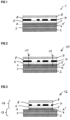
- FIGS 1 to 4 illustrate an embodiment of the use of a security element transfer material according to the invention according to the first aspect of the invention, which is used, for example, for the provision of the patch-shaped security element 34 in the Figure 9 is suitable.
- the dashed line AA' shows the area at which the upper material is detached from the temporary carrier later in the course of applying the upper material (ie the security element or transfer element to be applied to the value document) to a value document.
- the security element transfer material 1 contains a coextruded film, i.e. a composite film made of a polyethylene terephthalate (PET) film 4 with a thickness of 19 ⁇ m and a plastic layer 5 arranged thereon based on a foreign plastic material, in the example pure polyethylene naphthalate (PEN).
- PET polyethylene terephthalate
- PEN polyethylene naphthalate
- the coextruded film having layers 4 and 5 is a plastic film/plastic layer composite film that tends to delaminate along the imaginary line AA'.
- the coextruded film having layers 4 and 5 was then permanently bonded to another polyethylene terephthalate (PET) film 2 with a thickness of 12 ⁇ m by means of an adhesive layer 3.
- a UV embossing lacquer layer 6 was applied above the plastic layer 5, which is provided with microstructures and/or nanostructures (the embossing structures are not shown in the figure).
- the UV embossing lacquer layer 6 was then provided with a metallization 7, which is formed in the form of a pattern or in the form of characters.
- the metallization 7 contains recesses that form a so-called negative writing.
- the metallization 7 can be provided, for example, by means of a washing process known in the prior art, see, for example, the EP 1 972 462 A2 .
- a primer layer 8 was then applied above the metallization 7, which actually serves as a leveling protective varnish.
- an adhesive layer 9 suitable for bonding to a valuable document namely a heat-sealing varnish layer, was applied above the primer layer 8.
- the lines 11 shown indicate how the security element layer composite is cut in order to pre-cut the security elements in their outline shapes.
- the cutting can be done using a punch or using a suitable laser, e.g. a CO 2 laser.
- the cuts 11 penetrate the plastic film 4 of the temporary carrier.
- the plastic film 4 is destabilized by the cuts 11 and can easily tear at the locations of the cuts in the event of slight stretching, as is practically unavoidable during the transfer process of the security elements.
- the excess material of the security element layer composite (in the cross-sectional representation according to the Figure 2 the material outside the cuts 11) is removed in the so-called "weeding" step, which creates gaps in the security element layer composite.
- This state is in the Figure 3 shown.
- the coextruded The polyethylene naphthalate (PEN)-based plastic layer 5 with minimal adhesion to the temporary carrier substrate 4 facilitates the removal of excess material.
- Security elements 14 are located on both sides of the gap.
- the temporary carrier is designated with the reference number 13.
- the security elements 14 form islands, so to speak, which are arranged on the temporary carrier 13.
- Figure 3 shows the security element transfer material according to the invention as an endless belt in which only one security element 14 is located in the width direction. In practice, the endless belts can be wider and comprise a plurality of security elements 14 arranged next to one another.
- the Figure 4 shows the security element 14 after transferring the security element transfer material to a security paper 16.
- the security element 14 is connected to the security paper substrate 16 of a value document by means of the adhesive layer 9.
- Above the adhesive layer 9 is the primer layer 8, followed by the metallization 7, which has recesses and thus forms a pattern or symbol, and the UV embossing lacquer layer 6.
- PEN polyethylene naphthalate
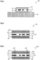
- the Figures 5 to 8 illustrate an embodiment of the use of a security element transfer material according to the second aspect of the invention, which is used e.g. for Provision of the patch-shaped security element 35 in the Figure 9
- the paper substrate 36 of the banknote 33 has a square recess 37 within the area of the patch-shaped security element 35, which can be obtained, for example, by punching or laser cutting.
- the recess 37 in the paper 36 is thus covered or closed on one side by the patch 35.
- the dashed line AA' shows the area at which the upper material is detached from the temporary carrier later in the course of applying the upper material (ie the security element or transfer element to be applied to the value document) to a value document.
- the security element transfer material 17 contains a coextruded film, i.e. a composite film made of a polyethylene terephthalate (PET) film 18 with a thickness of 19 ⁇ m and a plastic layer 19 based on polyethylene naphthalate (PEN) arranged thereon, to which a certain amount of polyethylene terephthalate (PET) is added.
- PET polyethylene terephthalate
- PEN polyethylene naphthalate
- the layers 18 and 19 form a plastic film/plastic layer composite film that is stable against delamination.
- a UV embossing lacquer layer 20 was then applied, which is provided with microstructures and/or nanostructures (the embossing structures are not shown in the figure).
- the UV embossing lacquer layer 20 was then provided with a metallization 21, which is formed in the form of a pattern or in the form of characters.
- the metallization 21 contains recesses that form a so-called negative writing.
- the provision of the metallization 21 can be done by means of a washing process known in the art, see e.g. EP 1 972 462 A2 .
- a primer layer 22 was then applied above the metallization 21, which actually serves as a leveling protective varnish.
- a stationary carrier substrate 24, namely a polyethylene terephthalate (PET) film, and an adhesive layer 25 suitable for bonding to a value document, namely a heat-sealing varnish layer, were applied above the primer layer 22 by means of an adhesive layer 23.
- PET polyethylene terephthalate
- the lines 27 shown indicate how the security element layer composite is cut in order to pre-cut the security elements in their outline shapes.
- the cutting can be carried out by means of a punch or by means of a suitable laser, eg a CO 2 laser.
- a suitable laser eg a CO 2 laser.
- the cuts 27 penetrate into the plastic layer 19 produced by coextrusion, but not into the plastic film 18 of the temporary carrier.
- the excess material of the security element layer composite (in the cross-sectional representation according to the Figure 6 the material outside the cuts 27) is removed in the so-called "weeding" step, which creates gaps in the security element layer composite.
- This state is in the Figure 7 shown.
- the plastic layer 19, based on polyethylene naphthalate (PEN) with added polyethylene terephthalate (PET), with high adhesion on the carrier substrate 18, produced by coextrusion serves as a release layer and facilitates the removal of excess material.
- Security elements 30 are located on both sides of the gap.
- the reference number 29 designates the temporary carrier.
- the security elements 30 form islands, so to speak, which are arranged on the temporary carrier 29.
- Figure 7 shows the security element transfer material according to the invention as an endless belt in which only one security element 30 is located in the width direction.
- the endless belts can be wider and comprise a plurality of security elements 30 arranged next to one another.
- the Figure 8 shows the security element 30 after transfer from the security element transfer material to a security paper 32.
- the security element 30 is connected to the security paper substrate 32 of a value document by means of the adhesive layer 25.
- the paper substrate 32 of the banknote 33 has a recess within the area of the patch-shaped security element 30, which can be obtained, for example, by punching or laser cutting.
- Above the adhesive layer 25 are the stationary carrier substrate 24, the adhesive layer 23, the primer layer 22, followed by the metallization 21 having recesses and thus forming a pattern or character, and the UV embossing lacquer layer 20 as a top layer.
Landscapes
- Engineering & Computer Science (AREA)
- Manufacturing & Machinery (AREA)
- Mechanical Engineering (AREA)
- General Chemical & Material Sciences (AREA)
- General Health & Medical Sciences (AREA)
- Toxicology (AREA)
- Health & Medical Sciences (AREA)
- Chemical Kinetics & Catalysis (AREA)
- Chemical & Material Sciences (AREA)
- Business, Economics & Management (AREA)
- Accounting & Taxation (AREA)
- Finance (AREA)
- Laminated Bodies (AREA)
- Credit Cards Or The Like (AREA)
Claims (17)
- Matériau de transfert d'élément de sécurité (1) présentant- un composite de couches d'élément de sécurité présentant une pluralité de couches, dont au moins une couche adhésive (9), une couche de caractéristique (6 ; 7) et une couche visible (5), la couche visible étant la couche qui fait face à un observateur après le transfert d'un élément de sécurité (34) sur un objet de valeur (33), et- un support temporaire qui est relié de manière détachable à la couche visible (5) du composite de couches d'élément de sécurité,- le support temporaire présentant au moins un premier substrat de support temporaire (4), à savoir un film de matière plastique,
caractérisé en ce que- la couche visible (5) du composite de couches d'élément de sécurité se présente sous la forme d'une couche de matière plastique produite par coextrusion sur le premier substrat de support temporaire (4), ayant un pouvoir adhésif faible sur le premier substrat de support temporaire (4). - Matériau de transfert d'élément de sécurité (1) selon la revendication 1, caractérisé en ce que le premier substrat de support temporaire (4) est un film de polyéthylène téréphtalate (PET) et la couche visible (5) du composite de couches d'élément de sécurité, qui se présente sous la forme d'une couche de matière plastique produite par coextrusion sur le premier substrat de support temporaire (4), ayant un pouvoir adhésif faible sur le premier substrat de support temporaire (4), est une couche de polyéthylène naphtalate (PEN) .
- Matériau de transfert d'élément de sécurité (1) selon la revendication 1 ou 2, caractérisé en ce que le support temporaire présente un composite de couches de support constitué d'un premier (4) et d'un deuxième (2) substrat de support temporaire, chacun étant un film de matière plastique et étant collé de manière inamovible au moyen d'une couche d'adhésif (3).
- Matériau de transfert d'élément de sécurité (1) selon l'une quelconque des revendications 1 à 3, caractérisé en ce que des formes de contour des éléments de sécurité sont prédécoupées dans le composite de couches d'élément de sécurité.
- Matériau de transfert d'élément de sécurité (1) selon la revendication 4, en référence à la revendication 3, caractérisé en ce que des formes de contour des éléments de sécurité sont prédécoupées dans le composite de couches d'élément de sécurité, les découpes (11) coupant éventuellement partiellement ou complètement le premier substrat de support temporaire (4) et coupant éventuellement partiellement ou complètement la couche adhésive (3), mais ne pénétrant pas dans le deuxième substrat de support temporaire (2), de telle sorte que le support temporaire peut être détaché en tant que composite de couches de support complet.
- Matériau de transfert d'élément de sécurité (1) selon la revendication 4 ou 5, caractérisé en ce que le matériau composite de couches est retiré du composite de couches d'élément de sécurité en dehors des formes de contour des éléments de sécurité, de telle sorte que le matériau de transfert d'élément de sécurité présente des lacunes dans le composite de couches d'élément de sécurité, tandis que le support temporaire ne présente pas de lacunes.
- Matériau de transfert d'élément de sécurité (1) selon l'une quelconque des revendications 1 à 4, caractérisé en ce que la couche de caractéristique présente une couche de vernis gaufré (6) et une métallisation ou un élément en couche mince coloré (7).
- Matériau de transfert d'élément de sécurité (17) présentant- un composite de couches d'élément de sécurité présentant une pluralité de couches dont au moins une couche adhésive (25), une couche de caractéristique (20 ; 21) et un substrat de support permanent (24), la couche de caractéristique (20 ; 21) étant identique à une couche visible, et la couche visible étant la couche qui fait face à un observateur après le transfert d'un élément de sécurité (35) sur un objet de valeur (33), et- un support temporaire relié de manière détachable à la couche visible du composite de couches d'élément de sécurité,- le support temporaire présentant un substrat de support (18), à savoir un film de matière plastique, et une couche de matière plastique (19) produite par coextrusion sur le substrat de support (18), ayant un pouvoir adhésif élevé sur le substrat de support (18) ; et- la couche visible du composite de couches d'élément de sécurité étant reliée de manière détachable à la couche de matière plastique (19) produite par coextrusion sur le substrat de support (18).
- Matériau de transfert d'élément de sécurité (17) selon la revendication 8, caractérisé en ce que le substrat de support (18) du support temporaire est un film de polyéthylène téréphtalate (PET) et la couche de matière plastique produite par coextrusion sur le substrat de support (18), ayant un pouvoir adhésif élevé (19) sur le substrat de support (18), est une couche de polyéthylène naphtalate (PEN) avec du polyéthylène téréphtalate (PET) mélangé.
- Matériau de transfert d'élément de sécurité (17) selon l'une quelconque des revendications 8 ou 9, caractérisé en ce que des formes de contour des éléments de sécurité sont prédécoupées dans le composite de couches d'élément de sécurité.
- Matériau de transfert d'élément de sécurité (17) selon l'une quelconque des revendications 8 ou 9, caractérisé en ce que des formes de contour des éléments de sécurité sont prédécoupées dans le composite de couches d'élément de sécurité, les découpes coupant éventuellement partiellement ou complètement la couche de matière plastique (19) produite par coextrusion sur le substrat de support (18), ayant un pouvoir adhésif élevé sur le substrat de support (18), mais ne pénétrant pas dans un substrat de support (18) du support temporaire, de telle sorte que le support temporaire peut être séparé sous forme de composite de couches de support complet.
- Matériau de transfert d'élément de sécurité (1) selon l'une quelconque des revendications 8 à 11, caractérisé en ce que la couche de caractéristique présente une couche de vernis gaufré (20) et une métallisation ou un élément en couche mince coloré (21).
- Matériau de transfert d'élément de sécurité (1, 17) selon l'une quelconque des revendications 7 ou 12, caractérisé en ce que l'élément en couche mince coloré (7, 21) est un élément en couche mince à basculement de couleur, qui donne à l'observateur des impressions de couleur différentes sous différents angles d'observation, ou un élément en couche mince semi-transparent, qui donne à l'observateur des impressions de couleur différentes lorsqu'il est observé en lumière incidente et lorsqu'il est observé en lumière transmise.
- Utilisation d'un matériau de transfert d'élément de sécurité (1, 17) selon l'une quelconque des revendications 1 à 13 pour sécuriser un objet de valeur, notamment un document de valeur (33), avec un élément de sécurité (34, 35).
- Utilisation selon la revendication 14 en référence à l'une quelconque des revendications 8 à 13, caractérisée en ce que l'objet de valeur est un document de valeur (33) présentant une ouverture traversante (37) et l'élément de sécurité (35) est appliqué de manière à recouvrir l'ouverture traversante (37).
- Procédé de fabrication d'un matériau de transfert d'élément de sécurité (1) selon l'une quelconque des revendications 1 à 7, présentant- la fourniture d'un substrat de support (4), à savoir d'un film de matière plastique, pourvu d'une couche de matière plastique (5) produite par coextrusion, la couche de matière plastique (5) produite par coextrusion sur le substrat de support (4) présentant un pouvoir adhésif faible sur le substrat de support (4) ; et- l'agencement d'un composite de couches d'élément de sécurité présentant au moins une couche adhésive (9) et une couche de caractéristique (6 ; 7) sur la couche de matière plastique produite par coextrusion.
- Procédé de fabrication d'un matériau de transfert d'élément de sécurité (17) selon l'une quelconque des revendications 8 à 12, présentant- la fourniture d'un substrat de support (18), à savoir d'un film de matière plastique, qui est pourvu d'une couche de matière plastique (19) produite par coextrusion, la couche de matière plastique (19) produite par coextrusion sur le substrat de support (18) présentant un pouvoir adhésif élevé sur le substrat de support (18) ; et- l'agencement sur la couche de matière plastique produite par coextrusion d'un composite de couches d'élément de sécurité présentant au moins une couche adhésive (25) et une couche de caractéristique.
Applications Claiming Priority (2)
| Application Number | Priority Date | Filing Date | Title |
|---|---|---|---|
| DE102019006977.3A DE102019006977A1 (de) | 2019-10-08 | 2019-10-08 | Sicherheitselement- Transfermaterial, Verfahren zum Herstellen desselben und Verwendung |
| PCT/EP2020/025442 WO2021069096A1 (fr) | 2019-10-08 | 2020-10-01 | Matériau de transfert d'élément de sécurité, son procédé de fabrication et utilisation |
Publications (2)
| Publication Number | Publication Date |
|---|---|
| EP4041568A1 EP4041568A1 (fr) | 2022-08-17 |
| EP4041568B1 true EP4041568B1 (fr) | 2025-02-26 |
Family
ID=72752866
Family Applications (1)
| Application Number | Title | Priority Date | Filing Date |
|---|---|---|---|
| EP20786455.4A Active EP4041568B1 (fr) | 2019-10-08 | 2020-10-01 | Matériau de transfert d'élément de sécurité, son procédé de fabrication et utilisation |
Country Status (4)
| Country | Link |
|---|---|
| EP (1) | EP4041568B1 (fr) |
| CN (1) | CN114514107B (fr) |
| DE (1) | DE102019006977A1 (fr) |
| WO (1) | WO2021069096A1 (fr) |
Families Citing this family (1)
| Publication number | Priority date | Publication date | Assignee | Title |
|---|---|---|---|---|
| EP4681935A1 (fr) | 2024-07-15 | 2026-01-21 | Hueck Folien Gesellschaft m.b.H. | Matériau en feuille pour éléments de sécurité sous forme de patchs en feuille |
Family Cites Families (16)
| Publication number | Priority date | Publication date | Assignee | Title |
|---|---|---|---|---|
| DE3932505C2 (de) | 1989-09-28 | 2001-03-15 | Gao Ges Automation Org | Datenträger mit einem optisch variablen Element |
| US20070211238A1 (en) | 2004-04-30 | 2007-09-13 | Giesecke & Devrient Gmbh | Security Element and Methods for the Production Thereof |
| DE102004053007A1 (de) * | 2004-10-29 | 2006-05-04 | Giesecke & Devrient Gmbh | Sicherheitselement und Verfahren zu seiner Herstellung |
| DE102005028162A1 (de) | 2005-02-18 | 2006-12-28 | Giesecke & Devrient Gmbh | Sicherheitselement und Verfahren zu seiner Herstellung |
| DE102005062648A1 (de) | 2005-12-23 | 2007-06-28 | Henkel Kgaa | Duftstofffixierung aus Wasch- und Reinigungsmitteln an harten und weichen Oberflächen |
| DE102007055112A1 (de) | 2007-01-05 | 2008-07-10 | Giesecke & Devrient Gmbh | Verfahren zur Herstellung von Sicherheitsfolien |
| DE102008012419A1 (de) * | 2007-10-31 | 2009-05-07 | Bundesdruckerei Gmbh | Polymerschichtverbund für ein Sicherheits- und/oder Wertdokument, Verfahren zu dessen Herstellung sowie Sicherheits- und/oder Wertdokument |
| DE102008028187A1 (de) | 2008-06-12 | 2009-12-17 | Giesecke & Devrient Gmbh | Sicherheitselement mit optisch variablem Element. |
| DE102008047641A1 (de) * | 2008-09-17 | 2010-04-15 | Giesecke & Devrient Gmbh | Sicherheitselement-Transfermaterial mit mehrschichtigem Träger |
| PL2504400T3 (pl) | 2009-11-27 | 2018-02-28 | Basf Se | Kompozycje powłokowe do elementów zabezpieczających i hologramów |
| DE102009058243A1 (de) | 2009-12-14 | 2011-06-16 | Giesecke & Devrient Gmbh | Dünnschichtelement mit Mehrschichtstruktur |
| DE102012020257A1 (de) | 2012-10-16 | 2014-04-17 | Giesecke & Devrient Gmbh | Optisch variables Flächenmuster |
| AT516128B1 (de) * | 2014-07-17 | 2018-05-15 | Hueck Folien Gmbh | Sicherheitselement mit Farbkippeffekt und Manipulationsnachweis |
| DE102015014505A1 (de) * | 2015-11-10 | 2017-05-11 | Giesecke & Devrient Gmbh | Sicherheitselement, Verfahren zum Herstellen desselben und mit dem Sicherheitselement ausgestatteter Datenträger |
| DE102015121849A1 (de) * | 2015-12-15 | 2017-06-22 | Ovd Kinegram Ag | Verfahren zur Herstellung eines Sicherheitselements sowie Transferfolie |
| DE102016015546A1 (de) * | 2016-12-27 | 2018-06-28 | Giesecke+Devrient Currency Technology Gmbh | Mehrlagiges Wertdokumentsubstrat |
-
2019
- 2019-10-08 DE DE102019006977.3A patent/DE102019006977A1/de not_active Withdrawn
-
2020
- 2020-10-01 WO PCT/EP2020/025442 patent/WO2021069096A1/fr not_active Ceased
- 2020-10-01 CN CN202080070529.4A patent/CN114514107B/zh active Active
- 2020-10-01 EP EP20786455.4A patent/EP4041568B1/fr active Active
Also Published As
| Publication number | Publication date |
|---|---|
| EP4041568A1 (fr) | 2022-08-17 |
| CN114514107A (zh) | 2022-05-17 |
| CN114514107B (zh) | 2024-11-01 |
| DE102019006977A1 (de) | 2021-04-08 |
| WO2021069096A1 (fr) | 2021-04-15 |
Similar Documents
| Publication | Publication Date | Title |
|---|---|---|
| EP3565722B1 (fr) | Document de valeur | |
| EP2344343B1 (fr) | Matériau de transfert d'élément de sécurité à support multicouche | |
| EP3075562A1 (fr) | Élément de sécurité avec microstructure | |
| EP3986719B1 (fr) | Substrat de sécurité et document de valeur fabriqué à partir de celui-ci | |
| DE10007916A1 (de) | Mehrschichtige, laminierte Karte mit eingelagertem, Reliefstrukturen aufweisenden Sicherheitselement | |
| WO2009127325A1 (fr) | Procédé de fabrication d’un document de sécurité ou de valeur | |
| WO2017028954A1 (fr) | Document de valeur | |
| EP3363652B1 (fr) | Matériau de transfert d'éléments de sécurité et son procédé de fabrication | |
| DE102007005416B4 (de) | Prägefolie und damit gebildeter Sicherheitsaufkleber | |
| EP2257841B1 (fr) | Élément de sécurité avec caractéristiques de polarisation | |
| EP3894232B1 (fr) | Procédé de fabrication d'un produit intermédiaire de feuille, produit intermédiaire de feuille ainsi que procédé de fabrication d'un produit | |
| EP3768521B1 (fr) | Procédé de fabrication d'un matériau de transfert à élément de sécurité | |
| WO2021069096A1 (fr) | Matériau de transfert d'élément de sécurité, son procédé de fabrication et utilisation | |
| EP4217207B1 (fr) | Procédé de fabrication d'un élément de sécurité optiquement variable | |
| EP2295234B1 (fr) | Billet de banque en film composite et son procédé de fabrication | |
| EP4054854B1 (fr) | Document de valeur | |
| WO2023232196A1 (fr) | Matériau de transfert d'élément de sécurité pour transférer des éléments de sécurité ayant une caractéristique d'authenticité micro-optique et procédé de production dudit matériau de transfert d'élément de sécurité | |
| WO2022128152A1 (fr) | Support de données comportant un substrat composite possédant un élément de sécurité disposé dans une zone de visualisation en transparence |
Legal Events
| Date | Code | Title | Description |
|---|---|---|---|
| STAA | Information on the status of an ep patent application or granted ep patent |
Free format text: STATUS: UNKNOWN |
|
| STAA | Information on the status of an ep patent application or granted ep patent |
Free format text: STATUS: THE INTERNATIONAL PUBLICATION HAS BEEN MADE |
|
| PUAI | Public reference made under article 153(3) epc to a published international application that has entered the european phase |
Free format text: ORIGINAL CODE: 0009012 |
|
| STAA | Information on the status of an ep patent application or granted ep patent |
Free format text: STATUS: REQUEST FOR EXAMINATION WAS MADE |
|
| 17P | Request for examination filed |
Effective date: 20220509 |
|
| AK | Designated contracting states |
Kind code of ref document: A1 Designated state(s): AL AT BE BG CH CY CZ DE DK EE ES FI FR GB GR HR HU IE IS IT LI LT LU LV MC MK MT NL NO PL PT RO RS SE SI SK SM TR |
|
| DAV | Request for validation of the european patent (deleted) | ||
| DAX | Request for extension of the european patent (deleted) | ||
| RAP3 | Party data changed (applicant data changed or rights of an application transferred) |
Owner name: GIESECKE+DEVRIENT CURRENCY TECHNOLOGY GMBH |
|
| P01 | Opt-out of the competence of the unified patent court (upc) registered |
Effective date: 20230519 |
|
| GRAP | Despatch of communication of intention to grant a patent |
Free format text: ORIGINAL CODE: EPIDOSNIGR1 |
|
| STAA | Information on the status of an ep patent application or granted ep patent |
Free format text: STATUS: GRANT OF PATENT IS INTENDED |
|
| INTG | Intention to grant announced |
Effective date: 20241121 |
|
| GRAS | Grant fee paid |
Free format text: ORIGINAL CODE: EPIDOSNIGR3 |
|
| GRAA | (expected) grant |
Free format text: ORIGINAL CODE: 0009210 |
|
| STAA | Information on the status of an ep patent application or granted ep patent |
Free format text: STATUS: THE PATENT HAS BEEN GRANTED |
|
| AK | Designated contracting states |
Kind code of ref document: B1 Designated state(s): AL AT BE BG CH CY CZ DE DK EE ES FI FR GB GR HR HU IE IS IT LI LT LU LV MC MK MT NL NO PL PT RO RS SE SI SK SM TR |
|
| REG | Reference to a national code |
Ref country code: GB Ref legal event code: FG4D Free format text: NOT ENGLISH |
|
| REG | Reference to a national code |
Ref country code: CH Ref legal event code: EP |
|
| REG | Reference to a national code |
Ref country code: DE Ref legal event code: R096 Ref document number: 502020010503 Country of ref document: DE |
|
| REG | Reference to a national code |
Ref country code: IE Ref legal event code: FG4D Free format text: LANGUAGE OF EP DOCUMENT: GERMAN |
|
| REG | Reference to a national code |
Ref country code: NL Ref legal event code: MP Effective date: 20250226 |
|
| PG25 | Lapsed in a contracting state [announced via postgrant information from national office to epo] |
Ref country code: RS Free format text: LAPSE BECAUSE OF FAILURE TO SUBMIT A TRANSLATION OF THE DESCRIPTION OR TO PAY THE FEE WITHIN THE PRESCRIBED TIME-LIMIT Effective date: 20250526 |
|
| PG25 | Lapsed in a contracting state [announced via postgrant information from national office to epo] |
Ref country code: FI Free format text: LAPSE BECAUSE OF FAILURE TO SUBMIT A TRANSLATION OF THE DESCRIPTION OR TO PAY THE FEE WITHIN THE PRESCRIBED TIME-LIMIT Effective date: 20250226 |
|
| PG25 | Lapsed in a contracting state [announced via postgrant information from national office to epo] |
Ref country code: PL Free format text: LAPSE BECAUSE OF FAILURE TO SUBMIT A TRANSLATION OF THE DESCRIPTION OR TO PAY THE FEE WITHIN THE PRESCRIBED TIME-LIMIT Effective date: 20250226 |
|
| PG25 | Lapsed in a contracting state [announced via postgrant information from national office to epo] |
Ref country code: ES Free format text: LAPSE BECAUSE OF FAILURE TO SUBMIT A TRANSLATION OF THE DESCRIPTION OR TO PAY THE FEE WITHIN THE PRESCRIBED TIME-LIMIT Effective date: 20250226 |
|
| REG | Reference to a national code |
Ref country code: LT Ref legal event code: MG9D |
|
| PG25 | Lapsed in a contracting state [announced via postgrant information from national office to epo] |
Ref country code: IS Free format text: LAPSE BECAUSE OF FAILURE TO SUBMIT A TRANSLATION OF THE DESCRIPTION OR TO PAY THE FEE WITHIN THE PRESCRIBED TIME-LIMIT Effective date: 20250626 Ref country code: NO Free format text: LAPSE BECAUSE OF FAILURE TO SUBMIT A TRANSLATION OF THE DESCRIPTION OR TO PAY THE FEE WITHIN THE PRESCRIBED TIME-LIMIT Effective date: 20250526 |
|
| PG25 | Lapsed in a contracting state [announced via postgrant information from national office to epo] |
Ref country code: NL Free format text: LAPSE BECAUSE OF FAILURE TO SUBMIT A TRANSLATION OF THE DESCRIPTION OR TO PAY THE FEE WITHIN THE PRESCRIBED TIME-LIMIT Effective date: 20250226 |
|
| PG25 | Lapsed in a contracting state [announced via postgrant information from national office to epo] |
Ref country code: HR Free format text: LAPSE BECAUSE OF FAILURE TO SUBMIT A TRANSLATION OF THE DESCRIPTION OR TO PAY THE FEE WITHIN THE PRESCRIBED TIME-LIMIT Effective date: 20250226 |
|
| PG25 | Lapsed in a contracting state [announced via postgrant information from national office to epo] |
Ref country code: PT Free format text: LAPSE BECAUSE OF FAILURE TO SUBMIT A TRANSLATION OF THE DESCRIPTION OR TO PAY THE FEE WITHIN THE PRESCRIBED TIME-LIMIT Effective date: 20250626 Ref country code: LV Free format text: LAPSE BECAUSE OF FAILURE TO SUBMIT A TRANSLATION OF THE DESCRIPTION OR TO PAY THE FEE WITHIN THE PRESCRIBED TIME-LIMIT Effective date: 20250226 |
|
| PG25 | Lapsed in a contracting state [announced via postgrant information from national office to epo] |
Ref country code: GR Free format text: LAPSE BECAUSE OF FAILURE TO SUBMIT A TRANSLATION OF THE DESCRIPTION OR TO PAY THE FEE WITHIN THE PRESCRIBED TIME-LIMIT Effective date: 20250527 Ref country code: BG Free format text: LAPSE BECAUSE OF FAILURE TO SUBMIT A TRANSLATION OF THE DESCRIPTION OR TO PAY THE FEE WITHIN THE PRESCRIBED TIME-LIMIT Effective date: 20250226 |
|
| PG25 | Lapsed in a contracting state [announced via postgrant information from national office to epo] |
Ref country code: SE Free format text: LAPSE BECAUSE OF FAILURE TO SUBMIT A TRANSLATION OF THE DESCRIPTION OR TO PAY THE FEE WITHIN THE PRESCRIBED TIME-LIMIT Effective date: 20250226 |
|
| PG25 | Lapsed in a contracting state [announced via postgrant information from national office to epo] |
Ref country code: SM Free format text: LAPSE BECAUSE OF FAILURE TO SUBMIT A TRANSLATION OF THE DESCRIPTION OR TO PAY THE FEE WITHIN THE PRESCRIBED TIME-LIMIT Effective date: 20250226 |
|
| PG25 | Lapsed in a contracting state [announced via postgrant information from national office to epo] |
Ref country code: DK Free format text: LAPSE BECAUSE OF FAILURE TO SUBMIT A TRANSLATION OF THE DESCRIPTION OR TO PAY THE FEE WITHIN THE PRESCRIBED TIME-LIMIT Effective date: 20250226 |
|
| PG25 | Lapsed in a contracting state [announced via postgrant information from national office to epo] |
Ref country code: IT Free format text: LAPSE BECAUSE OF FAILURE TO SUBMIT A TRANSLATION OF THE DESCRIPTION OR TO PAY THE FEE WITHIN THE PRESCRIBED TIME-LIMIT Effective date: 20250226 |
|
| PG25 | Lapsed in a contracting state [announced via postgrant information from national office to epo] |
Ref country code: EE Free format text: LAPSE BECAUSE OF FAILURE TO SUBMIT A TRANSLATION OF THE DESCRIPTION OR TO PAY THE FEE WITHIN THE PRESCRIBED TIME-LIMIT Effective date: 20250226 Ref country code: CZ Free format text: LAPSE BECAUSE OF FAILURE TO SUBMIT A TRANSLATION OF THE DESCRIPTION OR TO PAY THE FEE WITHIN THE PRESCRIBED TIME-LIMIT Effective date: 20250226 |
|
| PG25 | Lapsed in a contracting state [announced via postgrant information from national office to epo] |
Ref country code: RO Free format text: LAPSE BECAUSE OF FAILURE TO SUBMIT A TRANSLATION OF THE DESCRIPTION OR TO PAY THE FEE WITHIN THE PRESCRIBED TIME-LIMIT Effective date: 20250226 |
|
| PG25 | Lapsed in a contracting state [announced via postgrant information from national office to epo] |
Ref country code: SK Free format text: LAPSE BECAUSE OF FAILURE TO SUBMIT A TRANSLATION OF THE DESCRIPTION OR TO PAY THE FEE WITHIN THE PRESCRIBED TIME-LIMIT Effective date: 20250226 |
|
| REG | Reference to a national code |
Ref country code: DE Ref legal event code: R097 Ref document number: 502020010503 Country of ref document: DE |
|
| PLBE | No opposition filed within time limit |
Free format text: ORIGINAL CODE: 0009261 |
|
| STAA | Information on the status of an ep patent application or granted ep patent |
Free format text: STATUS: NO OPPOSITION FILED WITHIN TIME LIMIT |
|
| REG | Reference to a national code |
Ref country code: CH Ref legal event code: L10 Free format text: ST27 STATUS EVENT CODE: U-0-0-L10-L00 (AS PROVIDED BY THE NATIONAL OFFICE) Effective date: 20260107 |
|
| PGFP | Annual fee paid to national office [announced via postgrant information from national office to epo] |
Ref country code: DE Payment date: 20251020 Year of fee payment: 6 |
|
| PGFP | Annual fee paid to national office [announced via postgrant information from national office to epo] |
Ref country code: AT Payment date: 20251021 Year of fee payment: 6 |
|
| 26N | No opposition filed |
Effective date: 20251127 |
|
| REG | Reference to a national code |
Ref country code: CH Ref legal event code: H13 Free format text: ST27 STATUS EVENT CODE: U-0-0-H10-H13 (AS PROVIDED BY THE NATIONAL OFFICE) Effective date: 20260527 |
|
| PG25 | Lapsed in a contracting state [announced via postgrant information from national office to epo] |
Ref country code: LU Free format text: LAPSE BECAUSE OF NON-PAYMENT OF DUE FEES Effective date: 20251001 |
|
| REG | Reference to a national code |
Ref country code: BE Ref legal event code: MM Effective date: 20251031 |
|
| GBPC | Gb: european patent ceased through non-payment of renewal fee |
Effective date: 20251001 |
|
| PG25 | Lapsed in a contracting state [announced via postgrant information from national office to epo] |
Ref country code: LT Free format text: LAPSE BECAUSE OF FAILURE TO SUBMIT A TRANSLATION OF THE DESCRIPTION OR TO PAY THE FEE WITHIN THE PRESCRIBED TIME-LIMIT Effective date: 20250226 |
|
| PG25 | Lapsed in a contracting state [announced via postgrant information from national office to epo] |
Ref country code: MC Free format text: LAPSE BECAUSE OF FAILURE TO SUBMIT A TRANSLATION OF THE DESCRIPTION OR TO PAY THE FEE WITHIN THE PRESCRIBED TIME-LIMIT Effective date: 20250226 |
|
| PG25 | Lapsed in a contracting state [announced via postgrant information from national office to epo] |
Ref country code: GB Free format text: LAPSE BECAUSE OF NON-PAYMENT OF DUE FEES Effective date: 20251001 |
|
| PG25 | Lapsed in a contracting state [announced via postgrant information from national office to epo] |
Ref country code: CH Free format text: LAPSE BECAUSE OF NON-PAYMENT OF DUE FEES Effective date: 20251031 Ref country code: BE Free format text: LAPSE BECAUSE OF NON-PAYMENT OF DUE FEES Effective date: 20251031 |
|
| PG25 | Lapsed in a contracting state [announced via postgrant information from national office to epo] |
Ref country code: FR Free format text: LAPSE BECAUSE OF NON-PAYMENT OF DUE FEES Effective date: 20251031 |