EP4043615B1 - Installation d'électrolyse - Google Patents
Installation d'électrolyse Download PDFInfo
- Publication number
- EP4043615B1 EP4043615B1 EP22156377.8A EP22156377A EP4043615B1 EP 4043615 B1 EP4043615 B1 EP 4043615B1 EP 22156377 A EP22156377 A EP 22156377A EP 4043615 B1 EP4043615 B1 EP 4043615B1
- Authority
- EP
- European Patent Office
- Prior art keywords
- unit
- electrolyzer
- electrolysis
- auxiliary
- plant
- Prior art date
- Legal status (The legal status is an assumption and is not a legal conclusion. Google has not performed a legal analysis and makes no representation as to the accuracy of the status listed.)
- Active
Links
Images


Classifications
-
- C—CHEMISTRY; METALLURGY
- C25—ELECTROLYTIC OR ELECTROPHORETIC PROCESSES; APPARATUS THEREFOR
- C25B—ELECTROLYTIC OR ELECTROPHORETIC PROCESSES FOR THE PRODUCTION OF COMPOUNDS OR NON-METALS; APPARATUS THEREFOR
- C25B1/00—Electrolytic production of inorganic compounds or non-metals
- C25B1/01—Products
- C25B1/02—Hydrogen or oxygen
- C25B1/04—Hydrogen or oxygen by electrolysis of water
-
- C—CHEMISTRY; METALLURGY
- C25—ELECTROLYTIC OR ELECTROPHORETIC PROCESSES; APPARATUS THEREFOR
- C25B—ELECTROLYTIC OR ELECTROPHORETIC PROCESSES FOR THE PRODUCTION OF COMPOUNDS OR NON-METALS; APPARATUS THEREFOR
- C25B15/00—Operating or servicing cells
-
- C—CHEMISTRY; METALLURGY
- C25—ELECTROLYTIC OR ELECTROPHORETIC PROCESSES; APPARATUS THEREFOR
- C25B—ELECTROLYTIC OR ELECTROPHORETIC PROCESSES FOR THE PRODUCTION OF COMPOUNDS OR NON-METALS; APPARATUS THEREFOR
- C25B15/00—Operating or servicing cells
- C25B15/02—Process control or regulation
- C25B15/021—Process control or regulation of heating or cooling
-
- C—CHEMISTRY; METALLURGY
- C25—ELECTROLYTIC OR ELECTROPHORETIC PROCESSES; APPARATUS THEREFOR
- C25B—ELECTROLYTIC OR ELECTROPHORETIC PROCESSES FOR THE PRODUCTION OF COMPOUNDS OR NON-METALS; APPARATUS THEREFOR
- C25B15/00—Operating or servicing cells
- C25B15/08—Supplying or removing reactants or electrolytes; Regeneration of electrolytes
-
- C—CHEMISTRY; METALLURGY
- C25—ELECTROLYTIC OR ELECTROPHORETIC PROCESSES; APPARATUS THEREFOR
- C25B—ELECTROLYTIC OR ELECTROPHORETIC PROCESSES FOR THE PRODUCTION OF COMPOUNDS OR NON-METALS; APPARATUS THEREFOR
- C25B9/00—Cells or assemblies of cells; Constructional parts of cells; Assemblies of constructional parts, e.g. electrode-diaphragm assemblies; Process-related cell features
- C25B9/70—Assemblies comprising two or more cells
-
- Y—GENERAL TAGGING OF NEW TECHNOLOGICAL DEVELOPMENTS; GENERAL TAGGING OF CROSS-SECTIONAL TECHNOLOGIES SPANNING OVER SEVERAL SECTIONS OF THE IPC; TECHNICAL SUBJECTS COVERED BY FORMER USPC CROSS-REFERENCE ART COLLECTIONS [XRACs] AND DIGESTS
- Y02—TECHNOLOGIES OR APPLICATIONS FOR MITIGATION OR ADAPTATION AGAINST CLIMATE CHANGE
- Y02E—REDUCTION OF GREENHOUSE GAS [GHG] EMISSIONS, RELATED TO ENERGY GENERATION, TRANSMISSION OR DISTRIBUTION
- Y02E60/00—Enabling technologies; Technologies with a potential or indirect contribution to GHG emissions mitigation
- Y02E60/30—Hydrogen technology
- Y02E60/36—Hydrogen production from non-carbon containing sources, e.g. by water electrolysis
Definitions
- the invention relates to an electrolysis plant for producing hydrogen by means of
- Electrolysis see claim 1. Electrolysis systems are known in practice and can be used on an industrial scale to produce or generate pure hydrogen. Basically, an electrolysis system comprises at least one electrolyzer that is connected to auxiliary systems. The electrolyzer is the part of the system in which the actual electrolysis of the reactant takes place, i.e. in which, for example, water is broken down into hydrogen and oxygen. The electrolyzer is operated electrically by applying a direct voltage.
- the auxiliary systems that are connected to the electrolyzer include, for example, devices such as a water treatment system that is connected to a reactant water line leading to the electrolyzer, a gas treatment device, a gas washing device, a storage facility for the hydrogen produced and/or the like.
- Previous electrolysis plants of the type described above which can be so-called PEM (Proton Exchange Membrane) electrolysis plants or alkaline electrolysis plants, require a very large amount of space, especially for the production of hydrogen on an industrial scale, which in turn leads to long pipes and long cables between the auxiliary plants and the electrolyzers.
- PEM Proton Exchange Membrane
- the accessibility of the individual components, especially in emergency situations, is sometimes difficult due to the complex layout and the complex geometry of the pipes and cables.
- the arrangement of the individual components of the electrolysis plant must always be adapted to the respective task. A Scaling depending on the performance of the electrolysis plant is difficult.
- WO 2020/020611 A1 discloses, according to its summary, an electrolysis unit and a method for the electrochemical decomposition of water into hydrogen and oxygen.
- the electrolysis unit comprises at least two electrolysis modules. It further comprises exactly one first gas separation device for a first product gas comprising oxygen and exactly one second gas separation device for a second product gas comprising hydrogen.
- the first gas separation device is connected to each of the at least two electrolysis modules via a first line.
- the second gas separation device is connected to each of the electrolysis modules via a second line.
- the at least two first lines have the same first length.
- the at least two second lines also have the same second length.
- the invention is based on the object of creating an electrolysis plant for the production or generation of hydrogen by means of electrolysis, which has a clear arrangement and is easily scalable depending on the desired performance.
- an electrolysis plant for producing or generating hydrogen by means of electrolysis comprising two electrolyzer units, each comprising at least one electrolyzer module, and an auxiliary plant unit, wherein the auxiliary plant unit is arranged between the electrolyzer units and is connected to both electrolyzer units via a common piping unit, so that the auxiliary plant unit is jointly assigned to both electrolyzer units.
- electrolysis system is therefore proposed in which the electrolyzer units are each made up of an electrolyzer module or of several electrolyzer modules, which can in particular be arranged next to one another.
- the electrolyzer units which can in particular be arranged symmetrically with respect to the auxiliary system unit, are connected to a common pipe unit connected to the auxiliary system unit. This makes it possible to make the pipe unit compact and in particular to make the pipes and cables that connect the auxiliary system unit and the electrolyzer units short in comparison to the electrolysis systems known to date. Direct line paths can be provided between the auxiliary system unit and the electrolyzer units. This leads to significant cost savings.
- the cables running between the components can be kept shorter than in the state of the art, which is why, due to the lower electrical Losses can be reduced by using smaller cable sizes. This also reduces the costs of the entire system. If the cable sizes are kept the same as in the state of the art, the shorter cable lengths result in better operational efficiency.
- the electrolysis system according to the invention can be easily adapted to the space available at any given time.
- the construction of the electrolyzer units from, in particular, identical electrolyzer modules makes it possible to easily adapt the electrolysis system to the desired electrical output by using a corresponding number of electrolyzer modules per electrolyzer unit.
- the electrolysis system according to the invention is therefore easily scalable.
- the electrolyzer modules of the electrolysis system according to the invention basically have a substantially identical structure and are arranged next to one another in a line within an electrolyzer unit, which enables easy laying of the required pipes of the pipe unit and the required cables.
- the electrolysis plant according to the invention can be easily adapted and scaled to changing conditions. This saves costs and time when planning and implementing a new plant or a modified plant.
- each electrolyzer unit comprises an electrolyzer module
- the components the auxiliary plant unit and the piping unit and the piping of the piping unit may need to be adjusted or scaled accordingly.
- the electrolysis system according to the invention can be an alkaline electrolysis system in which the electrolyzer modules are each connected to a feed water supply line and optionally each to a lye supply line.
- the electrolysis system according to the invention can also be designed as a so-called PEM (Proton Exchange Membrane) electrolysis system in which only water is supplied to the electrolyzers as a reactant and the electrolysis of the water takes place on a membrane.
- PEM Protein Exchange Membrane
- the electrolysis plant according to the invention can be designed with a high electrical output, which can in particular be over 10 MW.
- the electrolyzer modules each comprise the actual electrolyzer and, if applicable, components that are specific to the electrolyzer in question, for example a lye separator, a lye pump or the like.
- the piping unit is advantageously designed such that it comprises T-pieces which are connected on the one hand to the two electrolyzer units and on the other hand to the auxiliary plant unit.
- the electrolyzer modules of the electrolysis arrangement according to the invention are each expediently provided with a voltage supply which can comprise a transformer designed for the required voltage (medium voltage or low voltage) and/or a rectifier which provides the direct voltage required for the electrolyzer in question.
- a voltage supply is then provided which adapts the available supply voltage (usually medium voltage or high voltage) to the voltage required for the electrolyzer in question by means of a suitable transformer and/or a suitable rectifier.
- the electrolyzer units each comprise at least two electrolyzer modules, which are arranged next to each other.
- the electrolyzer modules can be arranged so that they are adjacent to the auxiliary plant unit or are arranged next to each other in the transverse direction relative to the symmetry axis of the electrolysis plant.
- the number of electrolyzer modules per electrolyzer unit is not limited.
- the auxiliary unit of the electrolysis system preferably comprises a water treatment device which is connected to a reactant line of the piping unit leading to the electrolyzer modules and which treats the raw water provided in order to be able to provide the electrolyzer modules with the required water quality. If necessary, an additional water tank for the treated raw water may be required, which is arranged between the water treatment device and the reactant line.
- the auxiliary system unit preferably comprises a lye tank which is connected to a lye line of the piping unit which leads to the electrolyzer units.
- the lye stored in the lye tank is required for commissioning, maintenance and replacement of the lye in the electrolyzer modules.
- the auxiliary plant unit comprises a hydrogen storage unit which is connected to a hydrogen delivery line which is directly or indirectly connected to a product line of the piping unit.
- the product gas hydrogen can therefore be stored in the hydrogen storage unit.
- a hydrogen processing device can be provided which is connected upstream of the hydrogen delivery line.
- a gas scrubber for the hydrogen produced is also arranged upstream of the hydrogen delivery line. In the gas scrubber, any lye is washed out of the product gas hydrogen during alkaline electrolysis and then fed back to the electrolyzers together with the feed water. All of these elements are preferably elements that are part of the common central auxiliary plant unit.
- the electrolysis plant according to the invention can also comprise an oxygen storage arranged in the auxiliary plant unit, which is connected to an oxygen delivery line and serves to store the other product gas, oxygen.
- An oxygen processing device and/or a gas scrubber for the oxygen produced can be arranged upstream of the oxygen delivery line.
- the product gas storage can be omitted if the product gases produced are taken directly. If the oxygen shown is not used, the oxygen storage and the oxygen delivery line can of course be omitted. The oxygen preparation facility and the gas scrubber for oxygen can then also be omitted.
- the auxiliary plant unit of the electrolysis plant can comprise a gas processing device which is connected to the hydrogen discharge line.
- a corresponding gas processing device can be provided for oxygen, which is the other product gas.
- the gas processing devices can comprise components for drying the product gases and for other post-treatment of the product gases.
- the auxiliary plant unit for the product gases can comprise a compression device, which can be connected to the respective gas processing device. This allows the product gases to be provided with the gas pressure required in each case.
- the auxiliary system unit comprises a nitrogen storage unit which is connected to a nitrogen line of the piping unit.
- An inert gas in the form of nitrogen can be supplied to the electrolyzer units via the nitrogen line, for example for system flushing.
- Nitrogen can be stored in liquid or gaseous form. If the nitrogen is stored in liquid form, a nitrogen evaporator is also required. Other peripheral components designed in the usual way ensure that the nitrogen is provided for system flushing at a defined volume flow, in a defined pressure range, in a defined temperature range and with a defined quality at the relevant points in the electrolysis system.
- the auxiliary plant unit preferably further comprises a control and/or monitoring device for components of the auxiliary plant unit and components of the electrolyzer modules. It is conceivable that the control and/or monitoring device, which controls the operation of the electrolysis plant, is additionally connected to a remote control and/or monitoring device of the operator of the electrolysis plant, which is arranged outside the actual electrolysis plant.
- the auxiliary plant unit of the electrolysis plant preferably comprises an air conditioning device for the electrolyzer modules, which can comprise a heating device, a cooling device and/or a ventilation device.
- the electrolysis system comprises a cooling device for the electrolyzer modules, which is connected to the piping unit, so that the electrolyzer modules can be cooled during operation using a coolant via corresponding piping.
- the cooling device Since the cooling device requires a lot of space when the electrolysis system is designed on an industrial scale, it is preferably arranged in a separate unit that is arranged outside the electrolyzer units and outside the auxiliary plant unit. It is expedient if the cooling device is arranged on a roof of a building of the electrolysis system and/or in the immediate vicinity of at least one of the electrolyzer units or the auxiliary plant unit, whereby cooling water lines can be kept short.
- the cooling device can also be used to cool components of the auxiliary plant unit.
- the electrolyzer modules are arranged under a roof of the respective electrolyzer unit.
- the electrolyzer modules are arranged in a lightweight building of the electrolysis system, which preferably adjoins a part of the building in which a rectifier and/or a transformer of the respective electrolyzer module can be arranged.
- the auxiliary plant unit can comprise a covered interior area and/or an exterior area that is open at the top.
- Storage facilities, tanks, gas scrubbers, gasometers and/or the like can be arranged in the exterior area that is open at the top.
- the covered interior area which is preferably formed from a solid building, for example the control and/or monitoring device, the water treatment device, the air conditioning device, compressors for gas compression, gas treatment devices, gas analysis components and/or the like are arranged.
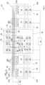
- an electrolysis plant 10 (not part of the invention) is shown, which has a modular structure and comprises a secondary plant unit 12 in a central arrangement, next to which an electrolyzer unit 14A or 14B is arranged on both sides in a symmetrical arrangement.
- the electrolyzer units 14A and 14B which each comprise an electrolyzer module 16 with an alkali electrolyzer 18, the product gases hydrogen H 2 and oxygen O 2 are produced starting from reactant water or feed water VE.
- the electrolyzer units 14A and 14B are connected to the auxiliary plant unit 12 via a common pipeline unit 20 and cables (not shown in detail).
- the pipeline unit 20 comprises a plurality of pipelines which are routed via so-called pipe bridges 22A and 22B from the auxiliary plant unit 12 to the electrolyzer units 14A and 14B.
- the electrolyzer modules 16 are each connected to a voltage supply which is connected to a central high-voltage transformer 24 which is provided with a switchgear and transforms a high-voltage alternating voltage into a medium-voltage alternating voltage.
- the medium voltage output by the high-voltage transformer 24 is converted by means of a medium-voltage transformer 26, which is assigned to the respective electrolyzer module 16, into a lower medium voltage or into a low voltage, which is converted by means of a respective rectifier 28 into a direct voltage which is provided or required for the operation of the respective electrolyzer 18.
- the medium-voltage transformers 26 are arranged in an outer area of the respective electrolyzer unit 14A or 14B.
- the rectifiers 28 are arranged in a solid construction part of the building, which adjoins a lightweight construction part in which the respective electrolyzer 18 is arranged.
- the switchgear of the high-voltage transformer 24 serves to distribute the voltages to the various medium-voltage transformers 26 and a medium-voltage transformer 30 of the auxiliary system unit 12.
- the medium-voltage transformer 30 of the auxiliary system unit 12 outputs a low voltage, which can be distributed to the relevant components of the electrolysis system 10 by means of a low-voltage sub-distribution device 31. Depending on the required electrical connection power, it is conceivable that these components are also operated directly with medium voltage.
- the auxiliary plant unit 12 comprises an outdoor area 32, which is open at the top, i.e. is not covered, and an indoor area 34, which is arranged in a solidly constructed building with a roof.
- a water treatment device 36 is arranged, which is connected to two gas scrubbers 40 and 42 via a line 38.
- the gas scrubber 40 which is arranged in the exterior area 32 of the auxiliary plant unit 12, is in turn connected via a line 44 to a T-piece 46, which is arranged in an educt line 48, which carries feed water VE as educt to the electrolyzers 18.
- a control and monitoring device 56 for the components of the electrolysis system 10 and an air conditioning device 58 are also arranged, by means of which the individual components of the electrolysis system 10 can be heated, cooled and/or ventilated.
- a compressed air generation device 60 with corresponding peripheral elements is arranged in the interior area 34, which is connected via a compressed air line 62 to a T-piece 46 of a compressed air line 64 of the pipe unit 20, wherein the compressed air DL guided in the compressed air line 62 can be used to switch the valves of the electrolysis system 10 (not shown in more detail).
- the compressed air generation device 60 ensures that the compressed air is provided with a defined volume flow, a defined pressure, a defined temperature and a defined quality at the relevant interfaces or valves of the electrolysis system 10.
- the interior area 34 of the auxiliary plant unit 12 further comprises a compressor 66, a gas processing device 68 and a gas analysis device 70 for the product gas hydrogen H 2 and a compressor 72, a gas processing device 74 and a gas analysis device 76 for the product gas oxygen O 2 .
- a hydrogen discharge line 78 branches off from the gas processing device 68 for hydrogen H 2 , which leads into the outer area 32 of the auxiliary system unit 12 and is connected to a hydrogen storage unit 80.
- An oxygen discharge line 82 branches off from the gas processing device 74 for oxygen O 2 , which is connected to an oxygen storage unit 84 arranged in the outer area 32.
- a lye tank 50 which is connected via a line 52 to a T-piece 46 of a lye line 54, via which lye can be supplied to the electrolyzers 18.
- a nitrogen storage device 86 with corresponding peripheral devices is arranged in the outer region 32 of the auxiliary plant unit 12, which is connected via a line 88 to a T-piece 46 of a nitrogen line 91, via which nitrogen N 2 can be supplied to the electrolyzers 18 as an inert gas for system flushing.
- a gasometer 90 is assigned to the gas scrubber 40 for hydrogen H 2 in the external area 32 of the auxiliary plant unit 12, which serves to ensure a constant gas pressure and as a buffer, wherein a product line 92 branches off between the gas scrubber 40 and the gasometer 90, which leads to the compressor 66 for hydrogen H 2 .
- the gas scrubber 42 for oxygen O 2 is assigned a gasometer 94, which also serves to ensure a constant gas pressure and as a buffer, wherein a product line 96 branches off between the gas scrubber 42 and the gasometer 94, which leads to the compressor 72 for oxygen O 2 .
- a cooling device 98 is arranged, which is connected to a coolant line 100 of the piping unit 20, via which coolant KM can be supplied to the electrolyzers 18.
- a hydrogen product line 102 branches off from the electrolyzers 18 and is connected to the gas scrubber 40 for hydrogen H 2 via a T-piece 46.
- an oxygen product line 104 branches off from the electrolyzers 18 and is connected to the gas scrubber 42 for oxygen O 2 via a T-piece 46.
- feed water VE is provided by the water treatment device 36 to produce hydrogen H 2 and oxygen O 2 and is passed through the gas scrubbers 40 and 42.
- the feed water VE passed through the gas scrubber 40 is fed via the reactant line 48 to the electrolyzers 18, each of which is filled with lye (in particular KOH) as an electrolyte.
- lye in particular KOH
- the direct current provided by the rectifiers 28 is used for electrolysis in the electrolyzers 18, so that hydrogen H 2 can be discharged via the product line 102 and oxygen O 2 via the product line 104.
- the hydrogen which is still contaminated with residual lye, is passed through the gas scrubber 40 and then fed to the gas processing device 68 via the line 92 and the compressor 66.
- the hydrogen storage device 80 From there it is fed to the hydrogen storage device 80 via the hydrogen discharge line 78.
- the gas scrubber 40 the residual lye is separated from the hydrogen H 2 by the water passed through in countercurrent and is returned to the electrolyzers 18 via the reactant line 48 together with the feed water VE.
- the oxygen O 2 produced by the electrolyzers 18 is fed to the gas scrubber 42 via the product line 104 and from there to the gas processing device 74 via the product line 96 and the compressor 72. From there, the oxygen O 2 purified of residual lye in the gas scrubber 42 is fed to the oxygen storage unit 84 via the oxygen discharge line 82. This residual lye is also fed back to the electrolyzers 18 together with the feed water VE. In the gas processing devices 68 and 74, the product gases hydrogen H 2 and oxygen O 2 are processed and further purified in order to achieve the required gas quality.
- the gas analysis devices 70 and 76 are used to check the quality of the product gases hydrogen H 2 and oxygen O 2 .
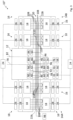
- an electrolysis plant 10' according to the invention is shown, which corresponds to the electrolysis plant according to Figure 1 a central auxiliary plant unit 12 and, with respect to an axis of symmetry of the electrolysis plant 10, an electrolyzer unit 14A or 14B on each side of the auxiliary plant unit 12.
- the electrolysis plant 10' represents a second stage of development, since the electrolyzer units 14A and 14B each comprise two electrolyzer modules 16 arranged next to one another, which are arranged in the manner according to the Figure 1 described type are connected to the central auxiliary unit 12 via a common pipe unit 20'.
- the corresponding pipes 48, 54, 64, 91, 100, 102 and 104 have additional T-pieces 106.
- the electrolyzer system 10' corresponds in terms of function and structure to that according to Figure 1 , which is why reference is made to the relevant description.
- an alkaline electrolysis plant 10" according to the invention is shown, which represents a third stage of development and also comprises a central auxiliary plant unit 12, which comprises an electrolyzer unit 14A and 14B on both sides with respect to an axis of symmetry of the plant 10", but which has four electrolyzer modules 16 with the Figure 1
- the four electrolyzer modules 16 are connected via T-pieces 108 and crossovers 110 to a common pipe unit 20" which connects the electrolyzer modules 16 to the auxiliary plant unit 12.
- the auxiliary plant unit 12 corresponds to the structure of the auxiliary plant unit according to Figure 1 .
- the structure and function of the electrolyzer system 10" also correspond to the structure and function of the electrolysis system according to Figure 1 , which is why reference is made to the relevant description.
- FIG 4 a second expansion stage of a PEM electrolysis plant 120 (not part of the invention) is shown, which also comprises a central auxiliary plant unit 12, which is arranged between two electrolyzer units 14A and 14B, each of which comprises two electrolyzer modules 16, whose electrolyzers 18 are each designed as PEM electrolyzers, in which water is decomposed at a membrane into hydrogen H 2 and oxygen O 2 and which operates without alkali.
- a central auxiliary plant unit 12 which is arranged between two electrolyzer units 14A and 14B, each of which comprises two electrolyzer modules 16, whose electrolyzers 18 are each designed as PEM electrolyzers, in which water is decomposed at a membrane into hydrogen H 2 and oxygen O 2 and which operates without alkali.
- the auxiliary plant unit 12 differs from the auxiliary plant unit of the embodiments according to the Figures 1 to 3 This is because no lye tank and no gas scrubbers with gasometers are arranged in the outside area 32. Rather, the product gases hydrogen H 2 and oxygen O 2 produced by the electrolyzers 18 are fed directly to the corresponding gas processing devices 68 and 74 via the hydrogen product line 102 and the oxygen product line 104 and via corresponding T-pieces 46 of the pipeline unit 20.
- the feed water VE (if necessary, fully demineralized water) produced by the water treatment plant 36 is led directly, without the interposition of gas scrubbers, via a T-piece 46 into the reactant line 48 and made available to the electrolyzers 18 for electrolysis.
- the structure of the electrolysis plant 120 essentially corresponds to the structure of the electrolysis plant according to Figure 2 , which is why, in order to avoid repetition, reference is made to the relevant description or the description of the electrolysis plant according to Figure 1 is referred to.
- a compressor is also required upstream of the gas processing equipment.
- the PEM electrolysis system can comprise only one electrolyzer module 16 per electrolyzer unit 14A and 14B in a first expansion stage.
- the PEM electrolysis system can comprise only one electrolyzer module 16 in accordance with the embodiment according to Figure 3 also include four electrolyzer modules 16 per electrolyzer unit. Expansion stages with three electrolyzer modules arranged next to each other or with a different number of electrolyzer modules per electrolyzer unit are also conceivable.
Landscapes
- Chemical & Material Sciences (AREA)
- Engineering & Computer Science (AREA)
- Chemical Kinetics & Catalysis (AREA)
- Electrochemistry (AREA)
- Materials Engineering (AREA)
- Metallurgy (AREA)
- Organic Chemistry (AREA)
- Automation & Control Theory (AREA)
- Inorganic Chemistry (AREA)
- Electrolytic Production Of Non-Metals, Compounds, Apparatuses Therefor (AREA)
Claims (14)
- Installation d'électrolyse pour l'affichage de l'hydrogène au moyen de l'électrolyse, l'installation d'électrolyse comprenant un transformateur à haute tension (24) central, deux unités d'électrolyseur (14A, 14B), qui comprend chacun au moins deux modules d'électrolyseur (16) adjacents, qui comprend chacun un électrolyseur (18) et une alimentation en énergie comprenant un transformateur (26) et/ou un redresseur (28), et une unité d'installation auxiliaire (12), les alimentations en énergie des modules d'électrolyseur (16) étant reliées au transformateur à haute tension (24) central et l'unité d'installation auxiliaire (12) étant disposée entre les unités d'électrolyseur (14A, 14B) et étant reliée aux deux unités d'électrolyseur (14A, 14B) par l'intermédiaire d'une unité de tuyau (20) commune de manière à ce que l'unité d'installation auxiliaire (12) est associée avec les deux unités d'électrolyseur (14A, 14B) ensemble, l'unité de tuyau (20) commune comprenant une pluralité de tuyaux qui s'étend à partir de l'unité d'installation auxiliaire (12) aux unités d'électrolyseur (14A, 14B), l'unité d'installation auxiliaire (12) comprenant un absorbeur-neutralisateur (49) pour l'hydrogène, qui est relié à un tuyau (102) de produit de hydrogène de l'unité de tuyau (20) par l'intermédiaire d'un té de branchement (46), le tuyau (102) de produit de hydrogène se branchant à partir des électrolyseurs (18), et un dispositif à refroidissement (98) étant prévu pour les modules d'électrolyseur (16) et étant relié à l'unité de tuyau (20).
- Installation d'électrolyse selon la revendication 1, caractérisée en ce que l'arrangement des unités d'électrolyseur (14A, 14B) est symétrique par rapport à l'unité d'installation auxiliaire (12).
- Installation d'électrolyse selon la revendication 1 ou la revendication 2, caractérisée en ce que l'unité de tuyau (20) comprends des tés de branchement (46) qui sont reliés aux deux unités d'électrolyseur (14A, 14B).
- Installation d'électrolyse selon l'une quelconque des revendications 1 à 3, caractérisée en ce que l'unité d'installation auxiliaire (12) comprend un dispositif (36) à traitement de l'eau qui est relié directement ou indirectement à un tuyau (48) de produit de départ de l'unité de tuyau (20).
- Installation d'électrolyse selon l'une quelconque des revendications 1 à 4, caractérisée en ce que l'unité d'installation auxiliaire (12) comprend un réservoir de lessive (50) qui est relié à un tuyau de lessive (54) de l'unité de tuyau (20).
- Installation d'électrolyse selon l'une quelconque des revendications 1 à 5, caractérisée en ce que l'unité d'installation auxiliaire (12) comprend un réservoir d'hydrogène (80) qui est relié à un tuyau (78) de décharge d'hydrogène relié directement ou indirectement à un tuyau de produit (102) de l'unité de tuyau (20).
- Installation d'électrolyse selon la revendication 6, caractérisée en ce que l'unité d'installation auxiliaire (12) comprend un dispositif (68) de traitement du gaz qui est relié au tuyau (78) de décharge d'hydrogène.
- Installation d'électrolyse selon la revendication 7, caractérisée en ce que l'unité d'installation auxiliaire (12) comprend un compresseur (66) qui est relié au dispositif (68) de traitement de gaz.
- Installation d'électrolyse selon l'une quelconque des revendications 1 à 8, caractérisée en ce que l'unité d'installation auxiliaire (12) comprend un réservoir de nitrogène (86) qui est relié au tuyau de nitrogène (91) de l'unité de tuyau (20).
- Installation d'électrolyse selon l'une quelconque des revendications 1 à 9, caractérisée en ce que l'unité d'installation auxiliaire (12) comprend un dispositif (56) de contrôle et/ou de surveillance pour des composants de l'unité d'installation auxiliaire (12) et pour des composants de modules d'électrolyseur (16).
- Installation d'électrolyse selon l'une quelconque des revendications 1 à 10, caractérisée en ce que l'unité d'installation auxiliaire (12) comprend une unité de climatisation (58) pour les modules d'électrolyseur (16).
- Installation d'électrolyse selon l'une quelconque des revendications 1 à 11, caractérisée en ce que les modules d'électrolyseur (16) sont disposés au-dessous d'une toiture de l'unité d'électrolyseur (14A, 14B) correspondante.
- Installation d'électrolyse selon l'une quelconque des revendications 1 à 12, caractérisée en ce que l'unité d'installation auxiliaire (12) comprend une zone intérieure (34) couverte.
- Installation d'électrolyse selon l'une quelconque des revendications 1 à 13, caractérisée en ce que l'unité d'installation auxiliaire (12) comprend une zone extérieure (32) qui est ouverte vers le haut.
Applications Claiming Priority (1)
| Application Number | Priority Date | Filing Date | Title |
|---|---|---|---|
| DE102021103191.5A DE102021103191A1 (de) | 2021-02-11 | 2021-02-11 | Elektrolyseanlage |
Publications (2)
| Publication Number | Publication Date |
|---|---|
| EP4043615A1 EP4043615A1 (fr) | 2022-08-17 |
| EP4043615B1 true EP4043615B1 (fr) | 2025-01-22 |
Family
ID=80447353
Family Applications (1)
| Application Number | Title | Priority Date | Filing Date |
|---|---|---|---|
| EP22156377.8A Active EP4043615B1 (fr) | 2021-02-11 | 2022-02-11 | Installation d'électrolyse |
Country Status (2)
| Country | Link |
|---|---|
| EP (1) | EP4043615B1 (fr) |
| DE (1) | DE102021103191A1 (fr) |
Families Citing this family (1)
| Publication number | Priority date | Publication date | Assignee | Title |
|---|---|---|---|---|
| FR3144171A1 (fr) * | 2022-12-21 | 2024-06-28 | Technip Energies France | Agencement d’électrolyseurs dans une architecture à étages |
Family Cites Families (5)
| Publication number | Priority date | Publication date | Assignee | Title |
|---|---|---|---|---|
| DE102014014091B4 (de) * | 2014-09-22 | 2026-01-15 | Kanadevia lnova AG | Verfahren und Anordnung zum Betreiben eines Elektrolyseurs, Elektrolyseanlage und Methanisierungsanlage |
| US10472723B2 (en) * | 2015-01-06 | 2019-11-12 | Thyssenkrupp Uhde Chlorine Engineers (Japan) Ltd. | Method of preventing reverse current flow through an ion exchange membrane electrolyzer |
| EP3489394B1 (fr) * | 2017-11-24 | 2020-08-19 | Siemens Aktiengesellschaft | Électrolyseur pour électrolyse pem à basse pression |
| EP3599292A1 (fr) * | 2018-07-27 | 2020-01-29 | Siemens Aktiengesellschaft | Unité d'électrolyse et procédé de fonctionnement de l'unité d'électrolyse |
| CN212451656U (zh) * | 2020-05-15 | 2021-02-02 | 张涛恭 | 氢氧发生组件及氢氧发生设备 |
-
2021
- 2021-02-11 DE DE102021103191.5A patent/DE102021103191A1/de not_active Ceased
-
2022
- 2022-02-11 EP EP22156377.8A patent/EP4043615B1/fr active Active
Also Published As
| Publication number | Publication date |
|---|---|
| EP4043615A1 (fr) | 2022-08-17 |
| DE102021103191A1 (de) | 2022-08-11 |
Similar Documents
| Publication | Publication Date | Title |
|---|---|---|
| EP3797182B1 (fr) | Unité d'électrolyse et procédé de fonctionnement de l'unité d'électrolyse | |
| EP3140435A1 (fr) | Procédé d'actionnement d'une installation d'électrolyse et installation d'électrolyse | |
| DE4223291A1 (de) | Aus systemeinheiten aufgebautes brennstoffzellen-energieerzeugungssystem | |
| DE102016213668A1 (de) | Verfahren und Anlage zur Herstellung von Alkoholen oder Kohlenwasserstoffen | |
| EP2803755B1 (fr) | Procédé de fonctionnement d'une installation d'électrolyse sous haute pression, installation d'électrolyse sous haute pression et distributeur d'hydrogène doté d'une installation d'électrolyse sous haute pression | |
| EP3572557A1 (fr) | Dispositif d'électrolyse et procédé de fonctionnement du dispositif d'électrolyse | |
| EP3520162B1 (fr) | Module de pile à combustible, système de pile à combustible et procédé de fonctionnement | |
| DE102020124497A1 (de) | System zur Energieerzeugung und Energiemanagement | |
| DE102014014091B4 (de) | Verfahren und Anordnung zum Betreiben eines Elektrolyseurs, Elektrolyseanlage und Methanisierungsanlage | |
| DE112016007528T5 (de) | Gaserzeugungsvorrichtung | |
| WO2011026670A2 (fr) | Installation et procédé de commande de l'installation pour la production de silicium polycristallin | |
| EP4043615A1 (fr) | Installation d'électrolyse | |
| EP1205002B1 (fr) | Dispositif destine a relier au moins deux batteries de piles a combustible et ensemble ainsi relie | |
| EP3489393A1 (fr) | Élément de raccordement permettant de raccorder de manière électrique et mécanique deux empilements de piles électrolytiques et dispositif d'électrolyse | |
| EP1303028B1 (fr) | Système pour alimenter un générateur en hydrogène | |
| DE102009037465B4 (de) | Stromverteilungsarchitektur für ein Luftfahrzeug | |
| EP1284517B1 (fr) | Combinaison de cellules à combustible | |
| DE102005004426A1 (de) | Brennstoffzellensystem mit Druckluftbetrieb | |
| DE102023204714A1 (de) | Vorrichtung zur Erzeugung von Wasserstoff durch Elektrolyse | |
| DE102018213404A1 (de) | Elektrolyseur und Verfahren zum Betreiben eines Elektrolyseurs | |
| DE212022000074U1 (de) | Ein RFQ-Wasserversorgungssystem, das die Echtzeitüberwachung und -wartung erleichtert | |
| DE102022204834A1 (de) | Wasserelektrolyseur-System | |
| EP1204811A1 (fr) | Centrale, en particulier centrale industrielle | |
| DE102024209054A1 (de) | Verbessertes Modul für Elektrolyseanlage | |
| EP4684047A1 (fr) | Système de production d'hydrogène en mer |
Legal Events
| Date | Code | Title | Description |
|---|---|---|---|
| PUAI | Public reference made under article 153(3) epc to a published international application that has entered the european phase |
Free format text: ORIGINAL CODE: 0009012 |
|
| STAA | Information on the status of an ep patent application or granted ep patent |
Free format text: STATUS: THE APPLICATION HAS BEEN PUBLISHED |
|
| AK | Designated contracting states |
Kind code of ref document: A1 Designated state(s): AL AT BE BG CH CY CZ DE DK EE ES FI FR GB GR HR HU IE IS IT LI LT LU LV MC MK MT NL NO PL PT RO RS SE SI SK SM TR |
|
| STAA | Information on the status of an ep patent application or granted ep patent |
Free format text: STATUS: REQUEST FOR EXAMINATION WAS MADE |
|
| 17P | Request for examination filed |
Effective date: 20230215 |
|
| RBV | Designated contracting states (corrected) |
Designated state(s): AL AT BE BG CH CY CZ DE DK EE ES FI FR GB GR HR HU IE IS IT LI LT LU LV MC MK MT NL NO PL PT RO RS SE SI SK SM TR |
|
| RAP3 | Party data changed (applicant data changed or rights of an application transferred) |
Owner name: KRAFTANLAGEN ENERGIES & SERVICES SE |
|
| GRAP | Despatch of communication of intention to grant a patent |
Free format text: ORIGINAL CODE: EPIDOSNIGR1 |
|
| STAA | Information on the status of an ep patent application or granted ep patent |
Free format text: STATUS: GRANT OF PATENT IS INTENDED |
|
| GRAJ | Information related to disapproval of communication of intention to grant by the applicant or resumption of examination proceedings by the epo deleted |
Free format text: ORIGINAL CODE: EPIDOSDIGR1 |
|
| STAA | Information on the status of an ep patent application or granted ep patent |
Free format text: STATUS: REQUEST FOR EXAMINATION WAS MADE |
|
| GRAP | Despatch of communication of intention to grant a patent |
Free format text: ORIGINAL CODE: EPIDOSNIGR1 |
|
| STAA | Information on the status of an ep patent application or granted ep patent |
Free format text: STATUS: GRANT OF PATENT IS INTENDED |
|
| INTG | Intention to grant announced |
Effective date: 20240731 |
|
| INTC | Intention to grant announced (deleted) | ||
| INTG | Intention to grant announced |
Effective date: 20240828 |
|
| GRAS | Grant fee paid |
Free format text: ORIGINAL CODE: EPIDOSNIGR3 |
|
| GRAA | (expected) grant |
Free format text: ORIGINAL CODE: 0009210 |
|
| STAA | Information on the status of an ep patent application or granted ep patent |
Free format text: STATUS: THE PATENT HAS BEEN GRANTED |
|
| AK | Designated contracting states |
Kind code of ref document: B1 Designated state(s): AL AT BE BG CH CY CZ DE DK EE ES FI FR GB GR HR HU IE IS IT LI LT LU LV MC MK MT NL NO PL PT RO RS SE SI SK SM TR |
|
| REG | Reference to a national code |
Ref country code: GB Ref legal event code: FG4D Free format text: NOT ENGLISH |
|
| REG | Reference to a national code |
Ref country code: CH Ref legal event code: EP |
|
| REG | Reference to a national code |
Ref country code: IE Ref legal event code: FG4D Free format text: LANGUAGE OF EP DOCUMENT: GERMAN |
|
| REG | Reference to a national code |
Ref country code: DE Ref legal event code: R096 Ref document number: 502022002682 Country of ref document: DE |
|
| REG | Reference to a national code |
Ref country code: NL Ref legal event code: MP Effective date: 20250122 |
|
| PG25 | Lapsed in a contracting state [announced via postgrant information from national office to epo] |
Ref country code: NL Free format text: LAPSE BECAUSE OF FAILURE TO SUBMIT A TRANSLATION OF THE DESCRIPTION OR TO PAY THE FEE WITHIN THE PRESCRIBED TIME-LIMIT Effective date: 20250122 |
|
| PG25 | Lapsed in a contracting state [announced via postgrant information from national office to epo] |
Ref country code: RS Free format text: LAPSE BECAUSE OF FAILURE TO SUBMIT A TRANSLATION OF THE DESCRIPTION OR TO PAY THE FEE WITHIN THE PRESCRIBED TIME-LIMIT Effective date: 20250422 |
|
| PG25 | Lapsed in a contracting state [announced via postgrant information from national office to epo] |
Ref country code: FI Free format text: LAPSE BECAUSE OF FAILURE TO SUBMIT A TRANSLATION OF THE DESCRIPTION OR TO PAY THE FEE WITHIN THE PRESCRIBED TIME-LIMIT Effective date: 20250122 |
|
| PG25 | Lapsed in a contracting state [announced via postgrant information from national office to epo] |
Ref country code: PL Free format text: LAPSE BECAUSE OF FAILURE TO SUBMIT A TRANSLATION OF THE DESCRIPTION OR TO PAY THE FEE WITHIN THE PRESCRIBED TIME-LIMIT Effective date: 20250122 |
|
| PGFP | Annual fee paid to national office [announced via postgrant information from national office to epo] |
Ref country code: DE Payment date: 20250424 Year of fee payment: 4 |
|
| PG25 | Lapsed in a contracting state [announced via postgrant information from national office to epo] |
Ref country code: ES Free format text: LAPSE BECAUSE OF FAILURE TO SUBMIT A TRANSLATION OF THE DESCRIPTION OR TO PAY THE FEE WITHIN THE PRESCRIBED TIME-LIMIT Effective date: 20250122 |
|
| REG | Reference to a national code |
Ref country code: LT Ref legal event code: MG9D |
|
| PG25 | Lapsed in a contracting state [announced via postgrant information from national office to epo] |
Ref country code: IS Free format text: LAPSE BECAUSE OF FAILURE TO SUBMIT A TRANSLATION OF THE DESCRIPTION OR TO PAY THE FEE WITHIN THE PRESCRIBED TIME-LIMIT Effective date: 20250522 Ref country code: NO Free format text: LAPSE BECAUSE OF FAILURE TO SUBMIT A TRANSLATION OF THE DESCRIPTION OR TO PAY THE FEE WITHIN THE PRESCRIBED TIME-LIMIT Effective date: 20250422 |
|
| PG25 | Lapsed in a contracting state [announced via postgrant information from national office to epo] |
Ref country code: HR Free format text: LAPSE BECAUSE OF FAILURE TO SUBMIT A TRANSLATION OF THE DESCRIPTION OR TO PAY THE FEE WITHIN THE PRESCRIBED TIME-LIMIT Effective date: 20250122 |
|
| PG25 | Lapsed in a contracting state [announced via postgrant information from national office to epo] |
Ref country code: PT Free format text: LAPSE BECAUSE OF FAILURE TO SUBMIT A TRANSLATION OF THE DESCRIPTION OR TO PAY THE FEE WITHIN THE PRESCRIBED TIME-LIMIT Effective date: 20250522 Ref country code: LV Free format text: LAPSE BECAUSE OF FAILURE TO SUBMIT A TRANSLATION OF THE DESCRIPTION OR TO PAY THE FEE WITHIN THE PRESCRIBED TIME-LIMIT Effective date: 20250122 |
|
| PG25 | Lapsed in a contracting state [announced via postgrant information from national office to epo] |
Ref country code: GR Free format text: LAPSE BECAUSE OF FAILURE TO SUBMIT A TRANSLATION OF THE DESCRIPTION OR TO PAY THE FEE WITHIN THE PRESCRIBED TIME-LIMIT Effective date: 20250423 Ref country code: BG Free format text: LAPSE BECAUSE OF FAILURE TO SUBMIT A TRANSLATION OF THE DESCRIPTION OR TO PAY THE FEE WITHIN THE PRESCRIBED TIME-LIMIT Effective date: 20250122 |
|
| PG25 | Lapsed in a contracting state [announced via postgrant information from national office to epo] |
Ref country code: SE Free format text: LAPSE BECAUSE OF FAILURE TO SUBMIT A TRANSLATION OF THE DESCRIPTION OR TO PAY THE FEE WITHIN THE PRESCRIBED TIME-LIMIT Effective date: 20250122 |
|
| PG25 | Lapsed in a contracting state [announced via postgrant information from national office to epo] |
Ref country code: SM Free format text: LAPSE BECAUSE OF FAILURE TO SUBMIT A TRANSLATION OF THE DESCRIPTION OR TO PAY THE FEE WITHIN THE PRESCRIBED TIME-LIMIT Effective date: 20250122 |
|
| PG25 | Lapsed in a contracting state [announced via postgrant information from national office to epo] |
Ref country code: DK Free format text: LAPSE BECAUSE OF FAILURE TO SUBMIT A TRANSLATION OF THE DESCRIPTION OR TO PAY THE FEE WITHIN THE PRESCRIBED TIME-LIMIT Effective date: 20250122 |
|
| PG25 | Lapsed in a contracting state [announced via postgrant information from national office to epo] |
Ref country code: MC Free format text: LAPSE BECAUSE OF FAILURE TO SUBMIT A TRANSLATION OF THE DESCRIPTION OR TO PAY THE FEE WITHIN THE PRESCRIBED TIME-LIMIT Effective date: 20250122 |
|
| PG25 | Lapsed in a contracting state [announced via postgrant information from national office to epo] |
Ref country code: LU Free format text: LAPSE BECAUSE OF NON-PAYMENT OF DUE FEES Effective date: 20250211 Ref country code: IT Free format text: LAPSE BECAUSE OF FAILURE TO SUBMIT A TRANSLATION OF THE DESCRIPTION OR TO PAY THE FEE WITHIN THE PRESCRIBED TIME-LIMIT Effective date: 20250122 |
|
| PG25 | Lapsed in a contracting state [announced via postgrant information from national office to epo] |
Ref country code: EE Free format text: LAPSE BECAUSE OF FAILURE TO SUBMIT A TRANSLATION OF THE DESCRIPTION OR TO PAY THE FEE WITHIN THE PRESCRIBED TIME-LIMIT Effective date: 20250122 Ref country code: CZ Free format text: LAPSE BECAUSE OF FAILURE TO SUBMIT A TRANSLATION OF THE DESCRIPTION OR TO PAY THE FEE WITHIN THE PRESCRIBED TIME-LIMIT Effective date: 20250122 |
|
| REG | Reference to a national code |
Ref country code: DE Ref legal event code: R097 Ref document number: 502022002682 Country of ref document: DE |
|
| PG25 | Lapsed in a contracting state [announced via postgrant information from national office to epo] |
Ref country code: RO Free format text: LAPSE BECAUSE OF FAILURE TO SUBMIT A TRANSLATION OF THE DESCRIPTION OR TO PAY THE FEE WITHIN THE PRESCRIBED TIME-LIMIT Effective date: 20250122 |
|
| PG25 | Lapsed in a contracting state [announced via postgrant information from national office to epo] |
Ref country code: SK Free format text: LAPSE BECAUSE OF FAILURE TO SUBMIT A TRANSLATION OF THE DESCRIPTION OR TO PAY THE FEE WITHIN THE PRESCRIBED TIME-LIMIT Effective date: 20250122 |
|
| PLBE | No opposition filed within time limit |
Free format text: ORIGINAL CODE: 0009261 |
|
| STAA | Information on the status of an ep patent application or granted ep patent |
Free format text: STATUS: NO OPPOSITION FILED WITHIN TIME LIMIT |
|
| REG | Reference to a national code |
Ref country code: CH Ref legal event code: L10 Free format text: ST27 STATUS EVENT CODE: U-0-0-L10-L00 (AS PROVIDED BY THE NATIONAL OFFICE) Effective date: 20251203 |
|
| REG | Reference to a national code |
Ref country code: BE Ref legal event code: MM Effective date: 20250228 |
|
| 26N | No opposition filed |
Effective date: 20251023 |
|
| PG25 | Lapsed in a contracting state [announced via postgrant information from national office to epo] |
Ref country code: FR Free format text: LAPSE BECAUSE OF NON-PAYMENT OF DUE FEES Effective date: 20250322 |
|
| PG25 | Lapsed in a contracting state [announced via postgrant information from national office to epo] |
Ref country code: BE Free format text: LAPSE BECAUSE OF NON-PAYMENT OF DUE FEES Effective date: 20250228 |
|
| PG25 | Lapsed in a contracting state [announced via postgrant information from national office to epo] |
Ref country code: IE Free format text: LAPSE BECAUSE OF NON-PAYMENT OF DUE FEES Effective date: 20250211 |
|
| REG | Reference to a national code |
Ref country code: CH Ref legal event code: U11 Free format text: ST27 STATUS EVENT CODE: U-0-0-U10-U11 (AS PROVIDED BY THE NATIONAL OFFICE) Effective date: 20260301 |
|
| PGFP | Annual fee paid to national office [announced via postgrant information from national office to epo] |
Ref country code: AT Payment date: 20260301 Year of fee payment: 5 |
|
| PGFP | Annual fee paid to national office [announced via postgrant information from national office to epo] |
Ref country code: CH Payment date: 20260301 Year of fee payment: 5 |