EP4043680A1 - Logement de paumelle - Google Patents
Logement de paumelle Download PDFInfo
- Publication number
- EP4043680A1 EP4043680A1 EP21156572.6A EP21156572A EP4043680A1 EP 4043680 A1 EP4043680 A1 EP 4043680A1 EP 21156572 A EP21156572 A EP 21156572A EP 4043680 A1 EP4043680 A1 EP 4043680A1
- Authority
- EP
- European Patent Office
- Prior art keywords
- clamping plate
- clamping
- frame part
- holder
- receiving housing
- Prior art date
- Legal status (The legal status is an assumption and is not a legal conclusion. Google has not performed a legal analysis and makes no representation as to the accuracy of the status listed.)
- Granted
Links
Images


Classifications
-
- E—FIXED CONSTRUCTIONS
- E05—LOCKS; KEYS; WINDOW OR DOOR FITTINGS; SAFES
- E05D—HINGES OR SUSPENSION DEVICES FOR DOORS, WINDOWS OR WINGS
- E05D7/00—Hinges or pivots of special construction
- E05D7/04—Hinges adjustable relative to the wing or the frame
-
- E—FIXED CONSTRUCTIONS
- E05—LOCKS; KEYS; WINDOW OR DOOR FITTINGS; SAFES
- E05D—HINGES OR SUSPENSION DEVICES FOR DOORS, WINDOWS OR WINGS
- E05D3/00—Hinges with pins
- E05D3/02—Hinges with pins with one pin
-
- E—FIXED CONSTRUCTIONS
- E05—LOCKS; KEYS; WINDOW OR DOOR FITTINGS; SAFES
- E05D—HINGES OR SUSPENSION DEVICES FOR DOORS, WINDOWS OR WINGS
- E05D5/00—Construction of single parts, e.g. the parts for attachment
- E05D5/02—Parts for attachment, e.g. flaps
- E05D5/04—Flat flaps
-
- E—FIXED CONSTRUCTIONS
- E05—LOCKS; KEYS; WINDOW OR DOOR FITTINGS; SAFES
- E05D—HINGES OR SUSPENSION DEVICES FOR DOORS, WINDOWS OR WINGS
- E05D7/00—Hinges or pivots of special construction
- E05D7/04—Hinges adjustable relative to the wing or the frame
- E05D2007/0461—Hinges adjustable relative to the wing or the frame in angular arrangement to the wing or the frame
-
- E—FIXED CONSTRUCTIONS
- E05—LOCKS; KEYS; WINDOW OR DOOR FITTINGS; SAFES
- E05D—HINGES OR SUSPENSION DEVICES FOR DOORS, WINDOWS OR WINGS
- E05D7/00—Hinges or pivots of special construction
- E05D7/04—Hinges adjustable relative to the wing or the frame
- E05D2007/0476—Pocket hinges
-
- E—FIXED CONSTRUCTIONS
- E05—LOCKS; KEYS; WINDOW OR DOOR FITTINGS; SAFES
- E05D—HINGES OR SUSPENSION DEVICES FOR DOORS, WINDOWS OR WINGS
- E05D7/00—Hinges or pivots of special construction
- E05D7/04—Hinges adjustable relative to the wing or the frame
- E05D2007/0492—Hinges adjustable relative to the wing or the frame in three directions
-
- E—FIXED CONSTRUCTIONS
- E05—LOCKS; KEYS; WINDOW OR DOOR FITTINGS; SAFES
- E05Y—INDEXING SCHEME ASSOCIATED WITH SUBCLASSES E05D AND E05F, RELATING TO CONSTRUCTION ELEMENTS, ELECTRIC CONTROL, POWER SUPPLY, POWER SIGNAL OR TRANSMISSION, USER INTERFACES, MOUNTING OR COUPLING, DETAILS, ACCESSORIES, AUXILIARY OPERATIONS NOT OTHERWISE PROVIDED FOR, APPLICATION THEREOF
- E05Y2600/00—Mounting or coupling arrangements for elements provided for in this subclass
- E05Y2600/50—Mounting methods; Positioning
- E05Y2600/502—Clamping
-
- E—FIXED CONSTRUCTIONS
- E05—LOCKS; KEYS; WINDOW OR DOOR FITTINGS; SAFES
- E05Y—INDEXING SCHEME ASSOCIATED WITH SUBCLASSES E05D AND E05F, RELATING TO CONSTRUCTION ELEMENTS, ELECTRIC CONTROL, POWER SUPPLY, POWER SIGNAL OR TRANSMISSION, USER INTERFACES, MOUNTING OR COUPLING, DETAILS, ACCESSORIES, AUXILIARY OPERATIONS NOT OTHERWISE PROVIDED FOR, APPLICATION THEREOF
- E05Y2600/00—Mounting or coupling arrangements for elements provided for in this subclass
- E05Y2600/50—Mounting methods; Positioning
- E05Y2600/51—Screwing or bolting
-
- E—FIXED CONSTRUCTIONS
- E05—LOCKS; KEYS; WINDOW OR DOOR FITTINGS; SAFES
- E05Y—INDEXING SCHEME ASSOCIATED WITH SUBCLASSES E05D AND E05F, RELATING TO CONSTRUCTION ELEMENTS, ELECTRIC CONTROL, POWER SUPPLY, POWER SIGNAL OR TRANSMISSION, USER INTERFACES, MOUNTING OR COUPLING, DETAILS, ACCESSORIES, AUXILIARY OPERATIONS NOT OTHERWISE PROVIDED FOR, APPLICATION THEREOF
- E05Y2800/00—Details, accessories and auxiliary operations not otherwise provided for
- E05Y2800/45—Manufacturing
-
- E—FIXED CONSTRUCTIONS
- E05—LOCKS; KEYS; WINDOW OR DOOR FITTINGS; SAFES
- E05Y—INDEXING SCHEME ASSOCIATED WITH SUBCLASSES E05D AND E05F, RELATING TO CONSTRUCTION ELEMENTS, ELECTRIC CONTROL, POWER SUPPLY, POWER SIGNAL OR TRANSMISSION, USER INTERFACES, MOUNTING OR COUPLING, DETAILS, ACCESSORIES, AUXILIARY OPERATIONS NOT OTHERWISE PROVIDED FOR, APPLICATION THEREOF
- E05Y2800/00—Details, accessories and auxiliary operations not otherwise provided for
- E05Y2800/67—Materials; Strength alteration thereof
- E05Y2800/674—Metal
-
- E—FIXED CONSTRUCTIONS
- E05—LOCKS; KEYS; WINDOW OR DOOR FITTINGS; SAFES
- E05Y—INDEXING SCHEME ASSOCIATED WITH SUBCLASSES E05D AND E05F, RELATING TO CONSTRUCTION ELEMENTS, ELECTRIC CONTROL, POWER SUPPLY, POWER SIGNAL OR TRANSMISSION, USER INTERFACES, MOUNTING OR COUPLING, DETAILS, ACCESSORIES, AUXILIARY OPERATIONS NOT OTHERWISE PROVIDED FOR, APPLICATION THEREOF
- E05Y2900/00—Application of doors, windows, wings or fittings thereof
- E05Y2900/10—Application of doors, windows, wings or fittings thereof for buildings or parts thereof
- E05Y2900/13—Type of wing
- E05Y2900/132—Doors
Definitions
- the present invention relates to a hinge mount for accommodating a frame part for installation in a frame for three-dimensional adjustment of the frame part relative to the hinge mount according to the preamble of claim 1.
- a generic tape recording for frame parts is for example from DE 202 10049 U1 known.
- the hinge seat shown there is used to hold commercially available frame parts or door hinges with a base body and a hinge flap extending from this, which is inserted through a lateral seat into the hinge seat and fixed there.
- the tape mount enables a three-dimensional adjustment of the frame part.
- the tape holder known from the above document has a clamping plate with three clamping screws that fix the frame part between the clamping plate and an adjustment plate. When the screws are loosened, the frame part can be moved in two dimensions.
- the adjustment in the third direction is achieved by turning the adjusting spindles with the clamping screws tightened, the adjusting spindles being coupled to the adjusting plate on the one hand and to a back plate on the other, whereby the adjusting plate with the frame part fixed to it via the clamping plate can be moved in the third direction by adjusting the adjusting spindles is adjustable.
- the hinge mount described above serves in particular to hold special frame parts of so-called object hinges, which are suitable for heavy doors.
- the two adjusting spindles For the adjustment in the direction of a frame seal of a frame, which determines the so-called contact pressure of the door, the two adjusting spindles must be turned evenly and alternately. It can happen that the frame part and the clamping plate and adjusting plate clamping it become inclined if the adjusting spindles are not rotated evenly.
- the adjusting spindles In order to be able to rotate the adjusting spindles, the adjusting spindles have to be mounted in a complex manner within the belt holder. Furthermore, a certain amount of play is necessary for the adjustment function of the adjusting spindles.
- the object of the present invention is to further develop a strap holder with a three-dimensional adjustment option such that the strap holder does not require such adjusting spindles.
- a hinge mount should be compact, be able to hold commercially available frame parts for light to medium-heavy doors and prevent the frame part from twisting when it is adjusted via the hinge mount.
- the tape holder according to the invention has a holder housing and a clamping unit arranged in the holder housing.
- the clamping unit has a first clamping plate and a second clamping plate, between which the frame part can be inserted in a first direction, and a clamping screw, with which the frame part inserted between the clamping plates can be clamped.
- the clamp unit is adjustable in the receiving housing in a second direction perpendicular to the first direction and in a third direction perpendicular to the first direction and the second direction.
- the clamping unit can be fixed to the receiving housing by means of at least one fixing screw and is mounted in the receiving housing so that it can be displaced in the third direction and pivoted about an axis parallel to the third direction when the fixing screw is loosened.
- the pivotable mounting of the clamping unit on the bottom of the receiving housing makes it possible to omit adjusting spindles, which enable the adjustment in the third direction in the tape holder known from the prior art, which considerably simplifies the construction of the tape holder.
- At least two pivot bearings are formed on mutually facing surfaces of the base of the receiving housing and the second clamping plate.
- Such pivot bearings can be molded onto the respective components in a simple manner, in particular in a case in which the recesses are punched into the bottom of the receiving housing and the projections into the second clamping plate.
- the at least one fixing screw is screwed through openings in the base of the receiving housing and the second clamping plate into a pressure plate which is arranged on a side of the base facing away from the second clamping plate.
- the opening in the second clamping plate is preferably designed as an elongated hole extending in the first direction and thus enables a tilted position of the second clamping plate relative to the fixing screw in a simple manner.
- a pivot bearing is arranged between the second clamping plate and a head of the fixing screw.
- a ring is placed on a neck of the fixing screw, the underside of which facing the second clamping plate is dome-shaped and rests on a dome embossing, the dome embossing being formed on a compensating plate resting on the second clamping plate.
- a pivot bearing can be provided in an extremely simple manner, which can preferably also be produced inexpensively by embossing the calotte embossing and using a commercially available ring with a calotte-shaped form.
- embossed webs extending in the first direction are formed on the first clamping plate and can be guided into corresponding grooves in the frame part.
- the length of the recesses on the bottom of the receiving housing is greater in the third direction than the length of the projections on the second clamping plate in the third direction.
- the fixing screws are screwed to the pressure plate through openings surrounded by the calotte embossings in the compensating plates, through the openings surrounded by the projections and through the openings in the bottom of the receiving housing surrounded by the partially cylindrical recesses.
- the pressure plate is preferably designed in one piece. In principle, a multi-part design of the pressure plate is also conceivable.
- top, bottom, left, right, front, rear, etc. refer exclusively to the exemplary representation and position of the tape holder, frame part, clamping plate, holder housing and the like chosen in the respective figures. These terms are not to be understood as limiting, i.e. these references can change due to different working positions or the mirror-symmetrical design or the like.
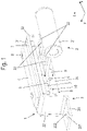
- figure 1 is denoted by the reference numeral 1 as a whole an embodiment of a tape holder according to the invention.
- the hinge mount 1 is used to hold a frame part 2 for installation in a frame 15, 16 for the three-dimensional adjustment of the frame part 2 relative to the hinge mount 1.
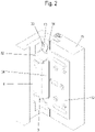
- FIG. 1 The built-in condition of the hinge mount 1 in a frame 15 made of wood is in figure 2 shown.
- a retaining plate 12 with a base 121 that can be screwed to the wooden frame is used here to fix the hinge mount 1 .
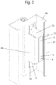
- the attachment to a frame 16 made of steel is preferably carried out by welding the receiving housing 3 of the strap holder 1 to a wall of the frame 16, as shown in figure 3 is shown.
- the receiving housing 3 has a base 31, from which end walls 32 extend on the front side, which are followed by uniformly bent tabs 33, which serve to fix the receiving housing 3 to the frame 15, 16.
- a rear wall 34 extends from one of the longitudinal edges of the base 31 of the receiving housing 3, so that overall there is an approximately cuboid receiving space which is enclosed on four of six sides.
- a clamping unit of the tape holder 1 is arranged on the bottom 31 in the holder housing 3 .
- the clamping unit has a first clamping plate 5 and a second clamping plate 6, between which the frame part 2 can be inserted in a first direction y, as indicated by the arrow in FIG figure 1 is indicated.
- a clamping screw 9 is used to fix the frame part 2, which, as shown in figure 6 as can be seen, can be screwed through an opening 52 in the first clamping plate 5 into a preferably threaded bore 61 in the second clamping plate 6 .
- the frame part 2 is a commercially available frame part 2 with a base body 21, from which two strap tabs 22 extend, which are pushed into the space between the first clamping plate and the second clamping plate 6 to fix it.
- grooves 23 are formed in the hinge tabs 22, which extend in the first direction y and receive the embossed webs 15 of the first clamping plate 5, so that the insertion of the frame part 2 between the first clamping plate 5 and the second clamping plate 6 by the interlocking the web embossing 51 and the grooves 23 are guided in the first direction y.
- the position of the frame part 2 relative to the receiving housing 3 can be adjusted in the first direction y by varying the insertion depth between the two clamping plates 5, 6 and can be fixed in this position in the clamping unit by subsequently tightening the clamping screw 9.
- This clamping unit consisting of the two clamping plates 5, 6 and the clamping screw 9 can be adjusted in the receiving housing 3 in a second direction z perpendicular to the first direction y and a third direction x perpendicular to the first direction y and the second direction z and by means of at least one fixing screw 8, in the exemplary embodiment shown, can be fixed to the receiving housing 3 by two such fixing screws 8.
- the clamping unit is mounted in the receiving housing 3 so that it can be displaced in the third direction x and pivoted about an axis parallel to the third direction x when the fixing screws 8 are loosened.
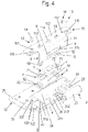
- the displacement of the clamping unit in the third direction x is as in figure 4 shown, made possible in that the second clamping plate 6 resting on the bottom 31 of the receiving housing 3 is displaceable in the third direction x.
- openings 62, 312 are provided in the base 31 of the receiving housing 3 and in the second clamping plate 6, through which one of the fixing screws 8 can be inserted.
- One end of the fixing screws 8 is screwed into a pressure plate 4 which is arranged on a side of the base 31 facing away from the second clamping plate 6 and is pressed against the base 31 by tightening the fixing screws 8 .
- the openings 312 on the bottom 31 of the receiving housing 3 are shaped as elongated holes extending in the third direction x, so that the second clamping plate 6 can be displaced overall in the third direction x, guided by the fixing screws 8 in the third direction x.
- the clamping unit is mounted in the receiving housing 3 such that it can pivot about an axis parallel to the third direction x.
- At least two pivot bearings each with a barrel-shaped projection 63 of the clamping plate 6 accommodated in a part-cylindrical recess 313, are formed on mutually facing surfaces of the base 31 of the receiving housing 3 and the second clamping plate 6, as shown in figure 4 and figure 7 is shown.
- the projections 63 are formed on the second clamping plate 6 and the recesses 313 are formed on the bottom 31 of the receiving housing 3 .
- a pivot bearing is arranged between the second clamping plate 6 and a head 81 of the fixing screw 8 in order to enable the clamping unit to be reliably fixed in any pivoted position relative to the base 31 of the receiving housing 3 by the fixing screws 8 .
- This pivot bearing is in the embodiment shown here, as in the figures 4 and 7 is represented by a ring 10 fitted on a neck 82 of the fixing screw 8 and a compensating plate 7 .
- the ring 10 is dome-shaped on its underside facing the second clamping plate 6 .
- a dome-shaped elevation referred to here as a dome embossing 71 .
- the compensating plate 7 lies flat on the second clamping plate 6 .
- the fixing screws 8 are passed through openings 72 surrounded by the calotte embossings 71 in the compensating plates 7, through the openings 62 surrounded by the projections 63 and through the openings 312 surrounded by the part-cylindrical recesses 313 in the bottom 31 of the receiving housing 3 with the pressure plate 4 screwed.
- the fixing screws 8 can always be aligned perpendicularly to the base 31 of the receiving housing 3 in any pivoting position of the second clamping plate 6 .
- the openings 62 in the second clamping plate 6 are designed as elongated holes extending in the first direction y.
- the length of the projections 63 on the second clamping plate 6 in the third direction x is smaller than the length of the recesses 312 on the bottom 31 of the receiving housing 3.
- the two open sides of the receiving housing 3 are preferably covered by a cover bracket 11 .
- the cover bracket 11 has a side wall 111 with an opening 115 through which the hinge tabs 22 of the frame part 2 are passed.
- the cover 112 bent perpendicularly to this side wall 111, has a plurality of elongated holes 113, 114 through which the fixing screws 8 and the clamping screw 9 can be fitted with a tool.
Landscapes
- Engineering & Computer Science (AREA)
- Mechanical Engineering (AREA)
- Hinges (AREA)
- Piezo-Electric Or Mechanical Vibrators, Or Delay Or Filter Circuits (AREA)
Priority Applications (4)
| Application Number | Priority Date | Filing Date | Title |
|---|---|---|---|
| EP21156572.6A EP4043680B1 (fr) | 2021-02-11 | 2021-02-11 | Logement de paumelle |
| HRP20230683TT HRP20230683T1 (hr) | 2021-02-11 | 2021-02-11 | Element za ugradnju šarki |
| PL21156572.6T PL4043680T3 (pl) | 2021-02-11 | 2021-02-11 | Gniazdo zawiasu |
| LTEP21156572.6T LT4043680T (lt) | 2021-02-11 | 2021-02-11 | Vyrių tvirtinimo elementas |
Applications Claiming Priority (1)
| Application Number | Priority Date | Filing Date | Title |
|---|---|---|---|
| EP21156572.6A EP4043680B1 (fr) | 2021-02-11 | 2021-02-11 | Logement de paumelle |
Publications (2)
| Publication Number | Publication Date |
|---|---|
| EP4043680A1 true EP4043680A1 (fr) | 2022-08-17 |
| EP4043680B1 EP4043680B1 (fr) | 2023-04-19 |
Family
ID=74591865
Family Applications (1)
| Application Number | Title | Priority Date | Filing Date |
|---|---|---|---|
| EP21156572.6A Active EP4043680B1 (fr) | 2021-02-11 | 2021-02-11 | Logement de paumelle |
Country Status (4)
| Country | Link |
|---|---|
| EP (1) | EP4043680B1 (fr) |
| HR (1) | HRP20230683T1 (fr) |
| LT (1) | LT4043680T (fr) |
| PL (1) | PL4043680T3 (fr) |
Families Citing this family (1)
| Publication number | Priority date | Publication date | Assignee | Title |
|---|---|---|---|---|
| CH720927A2 (de) * | 2023-07-07 | 2025-01-15 | Christian Sitter | Scharnier für Bauteile, vorzugsweise für ein schwenkbares Halten einer Türe oder eines Fensters in einem Rahmen |
Citations (5)
| Publication number | Priority date | Publication date | Assignee | Title |
|---|---|---|---|---|
| DE2951588A1 (de) * | 1979-12-21 | 1981-07-23 | Schwarte Fitschenfab Franz | Vorrichtung zum befestigen von scharnierlappen an zargen fuer tueren oder sonstige oeffnungsverschluesse |
| DE8717745U1 (de) * | 1987-09-23 | 1989-12-21 | Bunse, Friedhelm, 4783 Anröchte | Vorrichtung zur einstellbaren Befestigung eines Scharnierbandes (Tür, Fenster) an einer Stahlzarge |
| DE4431799C1 (de) * | 1994-09-07 | 1995-11-02 | Heine & Sohn Anuba Beschlaege | Tür- oder Fensterband |
| DE20210049U1 (de) | 2002-06-29 | 2003-02-20 | Bartels Systembeschläge GmbH, 32689 Kalletal | Bandaufnahmeelement für Block- und Futterzargen |
| EP2369109A2 (fr) * | 2010-03-20 | 2011-09-28 | Simonswerk, Gesellschaft mit beschränkter Haftung | Penture pour des portes de fermeture de bâtiments en bois feuillurées |
Family Cites Families (1)
| Publication number | Priority date | Publication date | Assignee | Title |
|---|---|---|---|---|
| DE10356403B3 (de) * | 2003-12-03 | 2004-10-28 | Simonswerk, Gmbh | Mehrdimensional verstellbares Türband |
-
2021
- 2021-02-11 HR HRP20230683TT patent/HRP20230683T1/hr unknown
- 2021-02-11 EP EP21156572.6A patent/EP4043680B1/fr active Active
- 2021-02-11 LT LTEP21156572.6T patent/LT4043680T/lt unknown
- 2021-02-11 PL PL21156572.6T patent/PL4043680T3/pl unknown
Patent Citations (5)
| Publication number | Priority date | Publication date | Assignee | Title |
|---|---|---|---|---|
| DE2951588A1 (de) * | 1979-12-21 | 1981-07-23 | Schwarte Fitschenfab Franz | Vorrichtung zum befestigen von scharnierlappen an zargen fuer tueren oder sonstige oeffnungsverschluesse |
| DE8717745U1 (de) * | 1987-09-23 | 1989-12-21 | Bunse, Friedhelm, 4783 Anröchte | Vorrichtung zur einstellbaren Befestigung eines Scharnierbandes (Tür, Fenster) an einer Stahlzarge |
| DE4431799C1 (de) * | 1994-09-07 | 1995-11-02 | Heine & Sohn Anuba Beschlaege | Tür- oder Fensterband |
| DE20210049U1 (de) | 2002-06-29 | 2003-02-20 | Bartels Systembeschläge GmbH, 32689 Kalletal | Bandaufnahmeelement für Block- und Futterzargen |
| EP2369109A2 (fr) * | 2010-03-20 | 2011-09-28 | Simonswerk, Gesellschaft mit beschränkter Haftung | Penture pour des portes de fermeture de bâtiments en bois feuillurées |
Also Published As
| Publication number | Publication date |
|---|---|
| PL4043680T3 (pl) | 2023-11-06 |
| HRP20230683T1 (hr) | 2023-10-13 |
| EP4043680B1 (fr) | 2023-04-19 |
| LT4043680T (lt) | 2023-09-25 |
Similar Documents
| Publication | Publication Date | Title |
|---|---|---|
| EP3680431B1 (fr) | Bande de recouvrement pour portes | |
| EP4155493A1 (fr) | Ferrure pour meuble | |
| EP2297418B1 (fr) | Charniere | |
| EP0223871B2 (fr) | Charnière ouvrant à 180 degrés | |
| DE202017102809U1 (de) | Vorrichtung zur Bewegung eines an einem Möbelkorpus eines Möbels aufgenommenen Möbelteils | |
| EP0590108B1 (fr) | Charniere de meuble | |
| EP1893836B1 (fr) | Charnière de meuble | |
| EP4043680B1 (fr) | Logement de paumelle | |
| DE4432862C1 (de) | Radiusbetätiger für einen Sicherheitsschalter | |
| CH687717A5 (de) | Tuer- oder Fensterband. | |
| EP0223186B1 (fr) | Penture réglable pour portes ou fenêtres | |
| DE19921796A1 (de) | Bandtasche für eine Scharnierkonstruktion | |
| EP3219891A1 (fr) | Système de charnière à réglage tridimensionnelle | |
| AT390471B (de) | Moebelscharnier mit einer seiten- und tiefeneinstelleinrichtung | |
| DE19732702A1 (de) | Bandlappen für ein Tür- oder Fensterband | |
| WO2020001841A1 (fr) | Ensemble d'une bande pour une liaison articulée avec charnière autour d'un axe de charnière d'un battant sur un cadre ainsi que bande pourvue de cet ensemble | |
| DE202021100681U1 (de) | Bandaufnahme | |
| WO2018121978A2 (fr) | Dispositif de serrage à genouillère | |
| CH692010A5 (de) | Vorrichtung zum Aufspannen und Ausrichten eines Werkzeugs oder Werkstücks. | |
| EP0837207B1 (fr) | Penture de porte | |
| WO2022194950A1 (fr) | Charnière destinée à une porte ou une fenêtre | |
| DE3040335C2 (fr) | ||
| WO1986000367A1 (fr) | Plaque de montage mobile verticalement pour une charniere de meuble | |
| DE3701053A1 (de) | Messerkopf | |
| EP4047165B1 (fr) | Penture dissimulée de porte |
Legal Events
| Date | Code | Title | Description |
|---|---|---|---|
| REG | Reference to a national code |
Ref country code: HR Ref legal event code: TUEP Ref document number: P20230683T Country of ref document: HR |
|
| PUAI | Public reference made under article 153(3) epc to a published international application that has entered the european phase |
Free format text: ORIGINAL CODE: 0009012 |
|
| STAA | Information on the status of an ep patent application or granted ep patent |
Free format text: STATUS: EXAMINATION IS IN PROGRESS |
|
| 17P | Request for examination filed |
Effective date: 20220511 |
|
| AK | Designated contracting states |
Kind code of ref document: A1 Designated state(s): AL AT BE BG CH CY CZ DE DK EE ES FI FR GB GR HR HU IE IS IT LI LT LU LV MC MK MT NL NO PL PT RO RS SE SI SK SM TR |
|
| GRAP | Despatch of communication of intention to grant a patent |
Free format text: ORIGINAL CODE: EPIDOSNIGR1 |
|
| STAA | Information on the status of an ep patent application or granted ep patent |
Free format text: STATUS: GRANT OF PATENT IS INTENDED |
|
| INTG | Intention to grant announced |
Effective date: 20230123 |
|
| GRAS | Grant fee paid |
Free format text: ORIGINAL CODE: EPIDOSNIGR3 |
|
| GRAA | (expected) grant |
Free format text: ORIGINAL CODE: 0009210 |
|
| STAA | Information on the status of an ep patent application or granted ep patent |
Free format text: STATUS: THE PATENT HAS BEEN GRANTED |
|
| AK | Designated contracting states |
Kind code of ref document: B1 Designated state(s): AL AT BE BG CH CY CZ DE DK EE ES FI FR GB GR HR HU IE IS IT LI LT LU LV MC MK MT NL NO PL PT RO RS SE SI SK SM TR |
|
| REG | Reference to a national code |
Ref country code: GB Ref legal event code: FG4D Free format text: NOT ENGLISH |
|
| REG | Reference to a national code |
Ref country code: DE Ref legal event code: R096 Ref document number: 502021000579 Country of ref document: DE |
|
| REG | Reference to a national code |
Ref country code: CH Ref legal event code: EP |
|
| REG | Reference to a national code |
Ref country code: IE Ref legal event code: FG4D Free format text: LANGUAGE OF EP DOCUMENT: GERMAN |
|
| REG | Reference to a national code |
Ref country code: AT Ref legal event code: REF Ref document number: 1561280 Country of ref document: AT Kind code of ref document: T Effective date: 20230515 |
|
| REG | Reference to a national code |
Ref country code: SE Ref legal event code: TRGR |
|
| REG | Reference to a national code |
Ref country code: NL Ref legal event code: FP |
|
| REG | Reference to a national code |
Ref country code: HR Ref legal event code: T1PR Ref document number: P20230683 Country of ref document: HR |
|
| PG25 | Lapsed in a contracting state [announced via postgrant information from national office to epo] |
Ref country code: PT Free format text: LAPSE BECAUSE OF FAILURE TO SUBMIT A TRANSLATION OF THE DESCRIPTION OR TO PAY THE FEE WITHIN THE PRESCRIBED TIME-LIMIT Effective date: 20230821 Ref country code: NO Free format text: LAPSE BECAUSE OF FAILURE TO SUBMIT A TRANSLATION OF THE DESCRIPTION OR TO PAY THE FEE WITHIN THE PRESCRIBED TIME-LIMIT Effective date: 20230719 Ref country code: ES Free format text: LAPSE BECAUSE OF FAILURE TO SUBMIT A TRANSLATION OF THE DESCRIPTION OR TO PAY THE FEE WITHIN THE PRESCRIBED TIME-LIMIT Effective date: 20230419 |
|
| PG25 | Lapsed in a contracting state [announced via postgrant information from national office to epo] |
Ref country code: RS Free format text: LAPSE BECAUSE OF FAILURE TO SUBMIT A TRANSLATION OF THE DESCRIPTION OR TO PAY THE FEE WITHIN THE PRESCRIBED TIME-LIMIT Effective date: 20230419 Ref country code: LV Free format text: LAPSE BECAUSE OF FAILURE TO SUBMIT A TRANSLATION OF THE DESCRIPTION OR TO PAY THE FEE WITHIN THE PRESCRIBED TIME-LIMIT Effective date: 20230419 Ref country code: IS Free format text: LAPSE BECAUSE OF FAILURE TO SUBMIT A TRANSLATION OF THE DESCRIPTION OR TO PAY THE FEE WITHIN THE PRESCRIBED TIME-LIMIT Effective date: 20230819 Ref country code: GR Free format text: LAPSE BECAUSE OF FAILURE TO SUBMIT A TRANSLATION OF THE DESCRIPTION OR TO PAY THE FEE WITHIN THE PRESCRIBED TIME-LIMIT Effective date: 20230720 |
|
| PG25 | Lapsed in a contracting state [announced via postgrant information from national office to epo] |
Ref country code: FI Free format text: LAPSE BECAUSE OF FAILURE TO SUBMIT A TRANSLATION OF THE DESCRIPTION OR TO PAY THE FEE WITHIN THE PRESCRIBED TIME-LIMIT Effective date: 20230419 |
|
| PG25 | Lapsed in a contracting state [announced via postgrant information from national office to epo] |
Ref country code: SK Free format text: LAPSE BECAUSE OF FAILURE TO SUBMIT A TRANSLATION OF THE DESCRIPTION OR TO PAY THE FEE WITHIN THE PRESCRIBED TIME-LIMIT Effective date: 20230419 |
|
| REG | Reference to a national code |
Ref country code: DE Ref legal event code: R097 Ref document number: 502021000579 Country of ref document: DE |
|
| PG25 | Lapsed in a contracting state [announced via postgrant information from national office to epo] |
Ref country code: SM Free format text: LAPSE BECAUSE OF FAILURE TO SUBMIT A TRANSLATION OF THE DESCRIPTION OR TO PAY THE FEE WITHIN THE PRESCRIBED TIME-LIMIT Effective date: 20230419 Ref country code: SK Free format text: LAPSE BECAUSE OF FAILURE TO SUBMIT A TRANSLATION OF THE DESCRIPTION OR TO PAY THE FEE WITHIN THE PRESCRIBED TIME-LIMIT Effective date: 20230419 Ref country code: RO Free format text: LAPSE BECAUSE OF FAILURE TO SUBMIT A TRANSLATION OF THE DESCRIPTION OR TO PAY THE FEE WITHIN THE PRESCRIBED TIME-LIMIT Effective date: 20230419 Ref country code: EE Free format text: LAPSE BECAUSE OF FAILURE TO SUBMIT A TRANSLATION OF THE DESCRIPTION OR TO PAY THE FEE WITHIN THE PRESCRIBED TIME-LIMIT Effective date: 20230419 Ref country code: DK Free format text: LAPSE BECAUSE OF FAILURE TO SUBMIT A TRANSLATION OF THE DESCRIPTION OR TO PAY THE FEE WITHIN THE PRESCRIBED TIME-LIMIT Effective date: 20230419 |
|
| REG | Reference to a national code |
Ref country code: HR Ref legal event code: ODRP Ref document number: P20230683 Country of ref document: HR Payment date: 20240131 Year of fee payment: 4 |
|
| PLBE | No opposition filed within time limit |
Free format text: ORIGINAL CODE: 0009261 |
|
| STAA | Information on the status of an ep patent application or granted ep patent |
Free format text: STATUS: NO OPPOSITION FILED WITHIN TIME LIMIT |
|
| 26N | No opposition filed |
Effective date: 20240122 |
|
| PG25 | Lapsed in a contracting state [announced via postgrant information from national office to epo] |
Ref country code: SI Free format text: LAPSE BECAUSE OF FAILURE TO SUBMIT A TRANSLATION OF THE DESCRIPTION OR TO PAY THE FEE WITHIN THE PRESCRIBED TIME-LIMIT Effective date: 20230419 |
|
| PG25 | Lapsed in a contracting state [announced via postgrant information from national office to epo] |
Ref country code: SI Free format text: LAPSE BECAUSE OF FAILURE TO SUBMIT A TRANSLATION OF THE DESCRIPTION OR TO PAY THE FEE WITHIN THE PRESCRIBED TIME-LIMIT Effective date: 20230419 |
|
| PG25 | Lapsed in a contracting state [announced via postgrant information from national office to epo] |
Ref country code: MC Free format text: LAPSE BECAUSE OF FAILURE TO SUBMIT A TRANSLATION OF THE DESCRIPTION OR TO PAY THE FEE WITHIN THE PRESCRIBED TIME-LIMIT Effective date: 20230419 |
|
| PG25 | Lapsed in a contracting state [announced via postgrant information from national office to epo] |
Ref country code: LU Free format text: LAPSE BECAUSE OF NON-PAYMENT OF DUE FEES Effective date: 20240211 |
|
| PG25 | Lapsed in a contracting state [announced via postgrant information from national office to epo] |
Ref country code: LU Free format text: LAPSE BECAUSE OF NON-PAYMENT OF DUE FEES Effective date: 20240211 |
|
| PG25 | Lapsed in a contracting state [announced via postgrant information from national office to epo] |
Ref country code: BG Free format text: LAPSE BECAUSE OF FAILURE TO SUBMIT A TRANSLATION OF THE DESCRIPTION OR TO PAY THE FEE WITHIN THE PRESCRIBED TIME-LIMIT Effective date: 20230419 |
|
| PG25 | Lapsed in a contracting state [announced via postgrant information from national office to epo] |
Ref country code: BG Free format text: LAPSE BECAUSE OF FAILURE TO SUBMIT A TRANSLATION OF THE DESCRIPTION OR TO PAY THE FEE WITHIN THE PRESCRIBED TIME-LIMIT Effective date: 20230419 |
|
| PG25 | Lapsed in a contracting state [announced via postgrant information from national office to epo] |
Ref country code: IE Free format text: LAPSE BECAUSE OF NON-PAYMENT OF DUE FEES Effective date: 20240211 |
|
| PG25 | Lapsed in a contracting state [announced via postgrant information from national office to epo] |
Ref country code: IE Free format text: LAPSE BECAUSE OF NON-PAYMENT OF DUE FEES Effective date: 20240211 |
|
| REG | Reference to a national code |
Ref country code: HR Ref legal event code: ODRP Ref document number: P20230683 Country of ref document: HR Payment date: 20250205 Year of fee payment: 5 |
|
| PG25 | Lapsed in a contracting state [announced via postgrant information from national office to epo] |
Ref country code: CY Free format text: LAPSE BECAUSE OF FAILURE TO SUBMIT A TRANSLATION OF THE DESCRIPTION OR TO PAY THE FEE WITHIN THE PRESCRIBED TIME-LIMIT; INVALID AB INITIO Effective date: 20210211 |
|
| PG25 | Lapsed in a contracting state [announced via postgrant information from national office to epo] |
Ref country code: HU Free format text: LAPSE BECAUSE OF FAILURE TO SUBMIT A TRANSLATION OF THE DESCRIPTION OR TO PAY THE FEE WITHIN THE PRESCRIBED TIME-LIMIT; INVALID AB INITIO Effective date: 20210211 |
|
| PG25 | Lapsed in a contracting state [announced via postgrant information from national office to epo] |
Ref country code: TR Free format text: LAPSE BECAUSE OF FAILURE TO SUBMIT A TRANSLATION OF THE DESCRIPTION OR TO PAY THE FEE WITHIN THE PRESCRIBED TIME-LIMIT Effective date: 20230419 |
|
| PGFP | Annual fee paid to national office [announced via postgrant information from national office to epo] |
Ref country code: PL Payment date: 20251204 Year of fee payment: 6 |
|
| REG | Reference to a national code |
Ref country code: CH Ref legal event code: U11 Free format text: ST27 STATUS EVENT CODE: U-0-0-U10-U11 (AS PROVIDED BY THE NATIONAL OFFICE) Effective date: 20260301 |
|
| REG | Reference to a national code |
Ref country code: HR Ref legal event code: ODRP Ref document number: P20230683 Country of ref document: HR Payment date: 20260204 Year of fee payment: 6 |
|
| PGFP | Annual fee paid to national office [announced via postgrant information from national office to epo] |
Ref country code: NL Payment date: 20260213 Year of fee payment: 6 |
|
| PGFP | Annual fee paid to national office [announced via postgrant information from national office to epo] |
Ref country code: SE Payment date: 20260216 Year of fee payment: 6 |
|
| PGFP | Annual fee paid to national office [announced via postgrant information from national office to epo] |
Ref country code: GB Payment date: 20260212 Year of fee payment: 6 Ref country code: LT Payment date: 20260129 Year of fee payment: 6 |
|
| PGFP | Annual fee paid to national office [announced via postgrant information from national office to epo] |
Ref country code: DE Payment date: 20251212 Year of fee payment: 6 |
|
| PGFP | Annual fee paid to national office [announced via postgrant information from national office to epo] |
Ref country code: HR Payment date: 20260204 Year of fee payment: 6 Ref country code: AT Payment date: 20260213 Year of fee payment: 6 |
|
| PGFP | Annual fee paid to national office [announced via postgrant information from national office to epo] |
Ref country code: BE Payment date: 20260206 Year of fee payment: 6 Ref country code: IT Payment date: 20260227 Year of fee payment: 6 |
|
| PGFP | Annual fee paid to national office [announced via postgrant information from national office to epo] |
Ref country code: FR Payment date: 20260212 Year of fee payment: 6 |
|
| PGFP | Annual fee paid to national office [announced via postgrant information from national office to epo] |
Ref country code: CH Payment date: 20260301 Year of fee payment: 6 Ref country code: CZ Payment date: 20260120 Year of fee payment: 6 |