EP4046546A1 - Lit, en particulier pour enfants, doté d'une construction de type maison - Google Patents
Lit, en particulier pour enfants, doté d'une construction de type maison Download PDFInfo
- Publication number
- EP4046546A1 EP4046546A1 EP22157270.4A EP22157270A EP4046546A1 EP 4046546 A1 EP4046546 A1 EP 4046546A1 EP 22157270 A EP22157270 A EP 22157270A EP 4046546 A1 EP4046546 A1 EP 4046546A1
- Authority
- EP
- European Patent Office
- Prior art keywords
- roof
- profile
- bed
- bed device
- traverse
- Prior art date
- Legal status (The legal status is an assumption and is not a legal conclusion. Google has not performed a legal analysis and makes no representation as to the accuracy of the status listed.)
- Granted
Links
Images


Classifications
-
- A—HUMAN NECESSITIES
- A47—FURNITURE; DOMESTIC ARTICLES OR APPLIANCES; COFFEE MILLS; SPICE MILLS; SUCTION CLEANERS IN GENERAL
- A47D—FURNITURE SPECIALLY ADAPTED FOR CHILDREN
- A47D15/00—Accessories for children's furniture, e.g. safety belts or baby-bottle holders
-
- A—HUMAN NECESSITIES
- A47—FURNITURE; DOMESTIC ARTICLES OR APPLIANCES; COFFEE MILLS; SPICE MILLS; SUCTION CLEANERS IN GENERAL
- A47C—CHAIRS; SOFAS; BEDS
- A47C19/00—Bedsteads
- A47C19/20—Multi-stage bedsteads; Bedsteads stackable to multi-stage bedsteads
-
- A—HUMAN NECESSITIES
- A47—FURNITURE; DOMESTIC ARTICLES OR APPLIANCES; COFFEE MILLS; SPICE MILLS; SUCTION CLEANERS IN GENERAL
- A47D—FURNITURE SPECIALLY ADAPTED FOR CHILDREN
- A47D7/00—Children's beds
Definitions
- the present invention relates to a bed device, in particular for children, with a house-like structure with a front, rear, end faces and roof surfaces with a base frame construction within which a support, in particular a slatted frame, with a mattress can be stored, bed side profiles optionally connected to the base frame construction as fall protection, vertical corner profile posts, to which the base frame construction is connected and which are arranged in the corner areas of the house-like structure, a connected traverse profile running in the longitudinal direction in the upper end area of the corner profile posts, roof edge profiles running on the front sides in the slope of the roof surface and connected to the upper end area of the corner profile posts , a roof traverse profile running in the longitudinal direction connected in the upper end area of the roof edge profiles, at least one wall panel connected in the area of the front and/or rear and at least one roof panel connected in the area of the roof surface.
- bed devices of the type mentioned are also called house beds.
- the facings or panels used there are simply connected to the bed frame with wood screws.
- a transformation of the house bed is either not possible or with great effort.
- a complex expansion blinding leaves unsightly or torn holes in the bed frame, which are caused by the screw connections.
- the present invention is based on the object or the technical problem of specifying a bed device that can be produced economically, has a reduced number of components, is highly flexible, and can be optically redesigned by the user in a simple manner can and as a system enables a wide variety of house beds, such as a ground-level snuggle bed, a lounger, a bunk, a play bed or a bunk bed.
- the bed device according to the invention is accordingly characterized in that the roof and wall panels have connection units which are designed in such a way that the panels can be detachably connected between the traverse profile and roof traverse profile and/or between the traverse profile and bed side profile without the use of a tool.
- a particularly preferred constructional configuration which enables the bed device to be manufactured economically as a bed system device, is characterized in that the wall panel and the roof panel are designed identically as system components.
- An improvement in the suitability of the system is also achieved by a further advantageous embodiment, which is characterized in that the truss profile and the roof truss profile are of the same design as system components.
- the corner profile posts and the roof edge profiles can be designed as system components with the same cross-section in an advantageous manner.
- each roof and wall panel has at least one, in particular two, hanging connection units spaced apart in the longitudinal direction in the lower edge area and at least one rotary connection unit in the upper edge area .
- an advantageous embodiment is characterized in that the traverse profile and the roof traverse profile have a continuous groove in the longitudinal direction.
- a particularly preferred practical embodiment according to a first variant is characterized in that the hook-in connection unit, when the wall panel is connected, positively engages behind or around the upper end area of the bed side profile or the base frame construction, at least in some areas, and the rotating connection unit grips the lower end area of the Traverse profile at least partially positively behind or surrounds.
- a particularly preferred configuration of a practical embodiment relating to the connection of the roof panels is characterized in that the hook-in connection unit engages in a form-fitting manner in the groove of the truss profile when the roof panel is connected and the rotary connection unit engages behind or around the lower end edge region of the roof truss profile at least in certain areas.
- a particularly advantageous embodiment that increases safety is characterized in that the rotary connection unit has a 3-way locking unit that locks the rotary connection unit against rotation and only releases a rotary movement when activated by pressing and pulling at the same time.
- the 3-way locking device prevents unauthorized assembly or disassembly of the panels, especially by small children, so that they cannot injure themselves through such attempted assembly work.
- the 3-way locking unit essentially represents a child safety device. In order to overcome this child safety device, the 3-way locking unit must first be pressed in at the side with your index finger and thumb and the twist lock must then be pulled out at the same time.
- the twist lock of the swivel connector unit which is urged into a detent by a spring when at rest, is released from its detent by pushing in and pulling from the side at the same time and can be rotated 90° to the new position to secure the panel to the bed frame .
- the wall panel has at least one window recess and is therefore also called a window panel.
- the wall or window panel is mounted parallel to the bed side profile and the traverse profile.
- the roof panel required for a fixed connection the same parallel requirement. Therefore, the truss profile is provided with an additional groove (milling) into which the suspension connection unit engages in the groove of the truss profile when installed.
- a particularly preferred embodiment is characterized in that the length of the roof panel/wall panel is 1 / n of the length of the bed device, where n ⁇ 2, in particular 4.
- a preferred practical embodiment is characterized in that the length of the wall panel/roof panel is a quarter of the length of the bed structure and three wall panels are arranged on the front, four roof panels on the roof and four wall panels on the back.
- the roof area is completely covered with roof panels and the front has an entrance, as the three wall panels do not take up the entire length of the bed structure.
- Another particularly preferred embodiment of the bed device according to the invention is characterized in that the base frame construction is arranged at a distance from the floor on the vertical corner profile posts, so that it is possible without any problems to produce, for example, bunk beds, play beds or bunk beds within the framework of a system for bed devices.
- an advantageous development is characterized in that the surface of the panels is printed or coated with motifs or is mechanically processed, in particular milled.
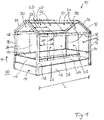
- a bed assembly 10 referred to as a house bed, intended for children.
- a rectangular base frame construction 12 is arranged on a floor 50, inside which a support or slatted frame, not shown, with a mattress placed on it is arranged.
- bed side profiles 14 are arranged on the front, rear and end faces, which serve as fall protection, with the bed side profile 14 having a shorter length on the front than the length L of the bed device 10.
- the base frame construction 12 is connected to vertical corner profile posts 16, which extend in the vertical direction H upwards.
- the roof construction is designed as a gabled roof, with the corner profile posts 16 being connected in opposite directions according to the roof pitch on both end faces in the upper end area of the corner profile posts 22, which are connected to one another in their upper end area.
- the roof construction can also be designed as a pent roof or flat roof or in another form.
- a traverse profile 18 running in the longitudinal direction L is connected both to the front and to the rear.
- a roof truss profile 20 running in the longitudinal direction L is connected in the end area of each roof edge profile 22 in the end area of each roof edge profile 22 .
- the sloping roof surfaces are each covered with four roof panels 24 lying next to one another in the longitudinal direction, which are each connected to the traverse profile 18 on the underside and to the roof traverse profile 20 on the upper side. The type of connection is described below.
- the roof panels 24 have a length LD and a height HD, and the wall panels 26 have a height HW and a length LW.
- the heights and lengths of both panels 24, 26 are identical.
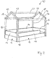
- FIG. 12 shows, in a schematic perspective, the bed device 10 according to FIG 1 without attached wall panels 26 and roof panels 24.
- a wall panel 26 or roof panel 24 with the height HW or HD and the length LW or LD is shown in a rectangular shape. Within the panel 24, 26 there may be a window recess 34 in 3 is shown in dashed lines.
- two suspension connection units 30 are connected, spaced apart in the longitudinal direction L.
- a rotary connection unit 32 is connected centrally to the upper edge end area, which can be locked and rotated by the angle of rotation D about an axis of rotation perpendicular to the plane of the panel 24 , 26 .
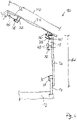
- the wall panel 26 is hung from the outside and from above via the hanging connection unit 30 on the upper edge end area of the bedside profile 14 .
- the suspension connection unit 30 has an L-shaped profile in cross section with a leg 38 pointing downwards, so that a form-fitting connection is provided.
- the inner contour of the L-shaped cross section is at least partially provided with a coating with a high coefficient of friction, for example a knobbed layer, so that when the wall panel 26 is inserted, an undesired or unintentional displacement in the longitudinal direction L is prevented.
- the wall panel 16 is connected to the lower end edge area of the traverse profile 18 via the rotary connection unit 32 .
- the rotary connector assembly 32 includes a projection assembly 48 that is rotatable about a pivot axis perpendicular to the plane of the wall panel 26 . In 4 the projection unit 48 is shown in the locked position. The projection unit 48 engages behind the lower end edge area of the traverse profile 18 in a form-fitting manner.
- the rotary connection unit 32 is provided with a child safety device, which is designed as a so-called 3-way locking unit (also called a triple lock).
- a child safety device which is designed as a so-called 3-way locking unit (also called a triple lock).
- 3-way locking unit also called a triple lock.
- the wall panels 26 and roof panels 24 are identical.
- the roof panel 24 is connected to the traverse profile 18 via the suspension connection unit 30.
- the traverse profile 18 has an inwardly open, inclined groove 40 corresponding to the pitch of the roof, into which the leg 38 of the suspension connection unit 30 engages in a form-fitting manner when connected.
- the rotary connection unit 32 is used, which is rotated into the corresponding locking position by turning the projection unit 48 analogously to the connection of the wall panel 26 to the traverse profile 18, after the childproof lock has been activated beforehand.
- connection situation of the connection of the panels 24, 26 via the hanging connection units 30 and the rotary connection unit 32 provides a problem-free, simple connection and a problem-free, simple detachment of the panels from the corresponding components. Furthermore, there is the possibility that the wall panel 26 is not as in 4 shown from the outside but alternatively also from the inside to the traverse profile 18 and the bed side profile 14 can be connected, which is not possible with the known bed devices.
- the bed device 10 according to the invention is designed as a bed system device, for example with the same wall and roof panels 24, 26, the same traverse profiles 18 and roof traverse profiles 20 and vertical corner profile posts 16 and roof edge profiles 22 with the same cross section, different variants of the bed device can be implemented easily and economically , For example, configuration of the bed device in addition to the embodiment according to 1 also as a lounger, bunk, play bed or bunk bed.
- FIG. 1 The formation of a bed device 10.1 as a bunk bed as a house bed is in figure 5 shown schematically.
- the upper area of the bed device 10.1 essentially corresponds to the bed device 10 according to FIG 1 .
- Identical components bear the same reference numbers and are not explained again.
- the vertical corner profile posts 16 are extended downwards and in the lower end area of the vertical corner profile posts 16 there is arranged a further base frame structure 42, within which a support or slatted frame and a mattress is arranged.
- a bed side profile 14 is arranged on each end face.
- a ladder 44 running to the floor 50 is present below the access 46 .
- a play bed differs from the bed device 10.1 according to figure 5 only in that there is no base frame construction 12 in the lower area, so that this area is available for children to play with.
Landscapes
- Health & Medical Sciences (AREA)
- General Health & Medical Sciences (AREA)
- Pediatric Medicine (AREA)
- Residential Or Office Buildings (AREA)
- Load-Bearing And Curtain Walls (AREA)
Applications Claiming Priority (1)
| Application Number | Priority Date | Filing Date | Title |
|---|---|---|---|
| DE202021000592.7U DE202021000592U1 (de) | 2021-02-17 | 2021-02-17 | Bettvorrichtung, insbesondere für Kinder, mit einem hausartigen Aufbau |
Publications (3)
| Publication Number | Publication Date |
|---|---|
| EP4046546A1 true EP4046546A1 (fr) | 2022-08-24 |
| EP4046546C0 EP4046546C0 (fr) | 2024-08-21 |
| EP4046546B1 EP4046546B1 (fr) | 2024-08-21 |
Family
ID=75683829
Family Applications (1)
| Application Number | Title | Priority Date | Filing Date |
|---|---|---|---|
| EP22157270.4A Active EP4046546B1 (fr) | 2021-02-17 | 2022-02-17 | Lit, en particulier pour enfants, doté d'une construction de type maison |
Country Status (2)
| Country | Link |
|---|---|
| EP (1) | EP4046546B1 (fr) |
| DE (1) | DE202021000592U1 (fr) |
Citations (3)
| Publication number | Priority date | Publication date | Assignee | Title |
|---|---|---|---|---|
| US1218102A (en) * | 1915-09-16 | 1917-03-06 | Frank Anderson Mershon | Bed. |
| USD791494S1 (en) * | 2015-03-20 | 2017-07-11 | M. Schack Engel A/S | Bed |
| AU2021106755A4 (en) * | 2021-08-24 | 2021-11-18 | Vuly Property Pty Ltd | Bed frame with telescopic canopy |
-
2021
- 2021-02-17 DE DE202021000592.7U patent/DE202021000592U1/de active Active
-
2022
- 2022-02-17 EP EP22157270.4A patent/EP4046546B1/fr active Active
Patent Citations (3)
| Publication number | Priority date | Publication date | Assignee | Title |
|---|---|---|---|---|
| US1218102A (en) * | 1915-09-16 | 1917-03-06 | Frank Anderson Mershon | Bed. |
| USD791494S1 (en) * | 2015-03-20 | 2017-07-11 | M. Schack Engel A/S | Bed |
| AU2021106755A4 (en) * | 2021-08-24 | 2021-11-18 | Vuly Property Pty Ltd | Bed frame with telescopic canopy |
Also Published As
| Publication number | Publication date |
|---|---|
| EP4046546C0 (fr) | 2024-08-21 |
| DE202021000592U1 (de) | 2021-04-12 |
| EP4046546B1 (fr) | 2024-08-21 |
Similar Documents
| Publication | Publication Date | Title |
|---|---|---|
| EP0264589A2 (fr) | Système de table | |
| EP0994664A1 (fr) | Ensemble d'elements de construction pour meubles | |
| EP0453409A1 (fr) | Dispositif de levage, notamment pour lits | |
| AT518814A1 (de) | Zaunsystem sowie Montageverfahren für ein Zaunsystem | |
| EP0952281A2 (fr) | Dispositif de clÔture | |
| EP4046546B1 (fr) | Lit, en particulier pour enfants, doté d'une construction de type maison | |
| DE3824142A1 (de) | Transportables zelt | |
| DE2435978A1 (de) | Stuetzkonstruktion fuer wand- oder deckenverkleidungen | |
| DE2848826A1 (de) | Auseinanderfaltbare vorrichtung zum vergroessern von fahrzeugen | |
| DE2330820A1 (de) | Bausatz fuer bandrasterprofilschienen mit 3- bzw. 6eckigem kreuzverbindungsstueck | |
| DE202019101810U1 (de) | Freistehendes, schraubenloses Möbel | |
| DE4135586C2 (de) | Belag für Baugerüste o. dgl. | |
| DE8716243U1 (de) | Bausatz für ein Bett | |
| DE102022103032A1 (de) | Haus | |
| DE2456522A1 (de) | Vorrichtung zur halterung von deckenplatten | |
| DE19840973A1 (de) | Raumsystem | |
| AT501871B1 (de) | Breitstegdecke | |
| DE102014106834A1 (de) | Neigungsverstellbare Treppe | |
| DE2123156A1 (de) | Fassade aus Fertigteilen | |
| DE29616968U1 (de) | Vorrichtung zum gegenseitigen Verbinden von Platten | |
| DE2949019A1 (de) | Transportabler verkaufsanhaenger | |
| DE3812528A1 (de) | Kabine, insbesondere umkleidekabine | |
| DE102019108314A1 (de) | Freistehendes, schraubenloses Möbel | |
| DE7800328U1 (de) | Ausstellungsfaltkonstruktion | |
| DE9202000U1 (de) | Klappstuhl |
Legal Events
| Date | Code | Title | Description |
|---|---|---|---|
| PUAI | Public reference made under article 153(3) epc to a published international application that has entered the european phase |
Free format text: ORIGINAL CODE: 0009012 |
|
| STAA | Information on the status of an ep patent application or granted ep patent |
Free format text: STATUS: THE APPLICATION HAS BEEN PUBLISHED |
|
| AK | Designated contracting states |
Kind code of ref document: A1 Designated state(s): AL AT BE BG CH CY CZ DE DK EE ES FI FR GB GR HR HU IE IS IT LI LT LU LV MC MK MT NL NO PL PT RO RS SE SI SK SM TR |
|
| RIN1 | Information on inventor provided before grant (corrected) |
Inventor name: AGOSTINO, BRUNO Inventor name: ROEDER, JOSEFINE |
|
| STAA | Information on the status of an ep patent application or granted ep patent |
Free format text: STATUS: REQUEST FOR EXAMINATION WAS MADE |
|
| 17P | Request for examination filed |
Effective date: 20230224 |
|
| RBV | Designated contracting states (corrected) |
Designated state(s): AL AT BE BG CH CY CZ DE DK EE ES FI FR GB GR HR HU IE IS IT LI LT LU LV MC MK MT NL NO PL PT RO RS SE SI SK SM TR |
|
| STAA | Information on the status of an ep patent application or granted ep patent |
Free format text: STATUS: EXAMINATION IS IN PROGRESS |
|
| 17Q | First examination report despatched |
Effective date: 20230428 |
|
| GRAP | Despatch of communication of intention to grant a patent |
Free format text: ORIGINAL CODE: EPIDOSNIGR1 |
|
| STAA | Information on the status of an ep patent application or granted ep patent |
Free format text: STATUS: GRANT OF PATENT IS INTENDED |
|
| INTG | Intention to grant announced |
Effective date: 20240322 |
|
| GRAS | Grant fee paid |
Free format text: ORIGINAL CODE: EPIDOSNIGR3 |
|
| GRAA | (expected) grant |
Free format text: ORIGINAL CODE: 0009210 |
|
| STAA | Information on the status of an ep patent application or granted ep patent |
Free format text: STATUS: THE PATENT HAS BEEN GRANTED |
|
| AK | Designated contracting states |
Kind code of ref document: B1 Designated state(s): AL AT BE BG CH CY CZ DE DK EE ES FI FR GB GR HR HU IE IS IT LI LT LU LV MC MK MT NL NO PL PT RO RS SE SI SK SM TR |
|
| REG | Reference to a national code |
Ref country code: GB Ref legal event code: FG4D Free format text: NOT ENGLISH |
|
| REG | Reference to a national code |
Ref country code: CH Ref legal event code: EP |
|
| REG | Reference to a national code |
Ref country code: DE Ref legal event code: R096 Ref document number: 502022001487 Country of ref document: DE |
|
| REG | Reference to a national code |
Ref country code: IE Ref legal event code: FG4D Free format text: LANGUAGE OF EP DOCUMENT: GERMAN |
|
| U01 | Request for unitary effect filed |
Effective date: 20240916 |
|
| U07 | Unitary effect registered |
Designated state(s): AT BE BG DE DK EE FI FR IT LT LU LV MT NL PT RO SE SI Effective date: 20240920 |
|
| PG25 | Lapsed in a contracting state [announced via postgrant information from national office to epo] |
Ref country code: NO Free format text: LAPSE BECAUSE OF FAILURE TO SUBMIT A TRANSLATION OF THE DESCRIPTION OR TO PAY THE FEE WITHIN THE PRESCRIBED TIME-LIMIT Effective date: 20241121 |
|
| PG25 | Lapsed in a contracting state [announced via postgrant information from national office to epo] |
Ref country code: PL Free format text: LAPSE BECAUSE OF FAILURE TO SUBMIT A TRANSLATION OF THE DESCRIPTION OR TO PAY THE FEE WITHIN THE PRESCRIBED TIME-LIMIT Effective date: 20240821 Ref country code: GR Free format text: LAPSE BECAUSE OF FAILURE TO SUBMIT A TRANSLATION OF THE DESCRIPTION OR TO PAY THE FEE WITHIN THE PRESCRIBED TIME-LIMIT Effective date: 20241122 |
|
| PG25 | Lapsed in a contracting state [announced via postgrant information from national office to epo] |
Ref country code: IS Free format text: LAPSE BECAUSE OF FAILURE TO SUBMIT A TRANSLATION OF THE DESCRIPTION OR TO PAY THE FEE WITHIN THE PRESCRIBED TIME-LIMIT Effective date: 20241221 |
|
| PG25 | Lapsed in a contracting state [announced via postgrant information from national office to epo] |
Ref country code: HR Free format text: LAPSE BECAUSE OF FAILURE TO SUBMIT A TRANSLATION OF THE DESCRIPTION OR TO PAY THE FEE WITHIN THE PRESCRIBED TIME-LIMIT Effective date: 20240821 |
|
| PG25 | Lapsed in a contracting state [announced via postgrant information from national office to epo] |
Ref country code: RS Free format text: LAPSE BECAUSE OF FAILURE TO SUBMIT A TRANSLATION OF THE DESCRIPTION OR TO PAY THE FEE WITHIN THE PRESCRIBED TIME-LIMIT Effective date: 20241121 Ref country code: ES Free format text: LAPSE BECAUSE OF FAILURE TO SUBMIT A TRANSLATION OF THE DESCRIPTION OR TO PAY THE FEE WITHIN THE PRESCRIBED TIME-LIMIT Effective date: 20240821 |
|
| PG25 | Lapsed in a contracting state [announced via postgrant information from national office to epo] |
Ref country code: RS Free format text: LAPSE BECAUSE OF FAILURE TO SUBMIT A TRANSLATION OF THE DESCRIPTION OR TO PAY THE FEE WITHIN THE PRESCRIBED TIME-LIMIT Effective date: 20241121 Ref country code: PL Free format text: LAPSE BECAUSE OF FAILURE TO SUBMIT A TRANSLATION OF THE DESCRIPTION OR TO PAY THE FEE WITHIN THE PRESCRIBED TIME-LIMIT Effective date: 20240821 Ref country code: NO Free format text: LAPSE BECAUSE OF FAILURE TO SUBMIT A TRANSLATION OF THE DESCRIPTION OR TO PAY THE FEE WITHIN THE PRESCRIBED TIME-LIMIT Effective date: 20241121 Ref country code: IS Free format text: LAPSE BECAUSE OF FAILURE TO SUBMIT A TRANSLATION OF THE DESCRIPTION OR TO PAY THE FEE WITHIN THE PRESCRIBED TIME-LIMIT Effective date: 20241221 Ref country code: HR Free format text: LAPSE BECAUSE OF FAILURE TO SUBMIT A TRANSLATION OF THE DESCRIPTION OR TO PAY THE FEE WITHIN THE PRESCRIBED TIME-LIMIT Effective date: 20240821 Ref country code: GR Free format text: LAPSE BECAUSE OF FAILURE TO SUBMIT A TRANSLATION OF THE DESCRIPTION OR TO PAY THE FEE WITHIN THE PRESCRIBED TIME-LIMIT Effective date: 20241122 Ref country code: ES Free format text: LAPSE BECAUSE OF FAILURE TO SUBMIT A TRANSLATION OF THE DESCRIPTION OR TO PAY THE FEE WITHIN THE PRESCRIBED TIME-LIMIT Effective date: 20240821 |
|
| U20 | Renewal fee for the european patent with unitary effect paid |
Year of fee payment: 4 Effective date: 20250227 |
|
| PG25 | Lapsed in a contracting state [announced via postgrant information from national office to epo] |
Ref country code: SM Free format text: LAPSE BECAUSE OF FAILURE TO SUBMIT A TRANSLATION OF THE DESCRIPTION OR TO PAY THE FEE WITHIN THE PRESCRIBED TIME-LIMIT Effective date: 20240821 |
|
| PG25 | Lapsed in a contracting state [announced via postgrant information from national office to epo] |
Ref country code: CZ Free format text: LAPSE BECAUSE OF FAILURE TO SUBMIT A TRANSLATION OF THE DESCRIPTION OR TO PAY THE FEE WITHIN THE PRESCRIBED TIME-LIMIT Effective date: 20240821 |
|
| PG25 | Lapsed in a contracting state [announced via postgrant information from national office to epo] |
Ref country code: SK Free format text: LAPSE BECAUSE OF FAILURE TO SUBMIT A TRANSLATION OF THE DESCRIPTION OR TO PAY THE FEE WITHIN THE PRESCRIBED TIME-LIMIT Effective date: 20240821 |
|
| PLBE | No opposition filed within time limit |
Free format text: ORIGINAL CODE: 0009261 |
|
| STAA | Information on the status of an ep patent application or granted ep patent |
Free format text: STATUS: NO OPPOSITION FILED WITHIN TIME LIMIT |
|
| 26N | No opposition filed |
Effective date: 20250522 |
|
| PG25 | Lapsed in a contracting state [announced via postgrant information from national office to epo] |
Ref country code: MC Free format text: LAPSE BECAUSE OF FAILURE TO SUBMIT A TRANSLATION OF THE DESCRIPTION OR TO PAY THE FEE WITHIN THE PRESCRIBED TIME-LIMIT Effective date: 20240821 |
|
| PG25 | Lapsed in a contracting state [announced via postgrant information from national office to epo] |
Ref country code: IE Free format text: LAPSE BECAUSE OF NON-PAYMENT OF DUE FEES Effective date: 20250217 |
|
| REG | Reference to a national code |
Ref country code: CH Ref legal event code: U11 Free format text: ST27 STATUS EVENT CODE: U-0-0-U10-U11 (AS PROVIDED BY THE NATIONAL OFFICE) Effective date: 20260301 |
|
| U20 | Renewal fee for the european patent with unitary effect paid |
Year of fee payment: 5 Effective date: 20260224 |
|
| PGFP | Annual fee paid to national office [announced via postgrant information from national office to epo] |
Ref country code: CH Payment date: 20260301 Year of fee payment: 5 |