EP4048190B1 - Gingivaformer für ein zahnimplantat - Google Patents
Gingivaformer für ein zahnimplantat Download PDFInfo
- Publication number
- EP4048190B1 EP4048190B1 EP20789621.8A EP20789621A EP4048190B1 EP 4048190 B1 EP4048190 B1 EP 4048190B1 EP 20789621 A EP20789621 A EP 20789621A EP 4048190 B1 EP4048190 B1 EP 4048190B1
- Authority
- EP
- European Patent Office
- Prior art keywords
- head
- foot
- axis
- healing abutment
- implant
- Prior art date
- Legal status (The legal status is an assumption and is not a legal conclusion. Google has not performed a legal analysis and makes no representation as to the accuracy of the status listed.)
- Active
Links
Images


Classifications
-
- A—HUMAN NECESSITIES
- A61—MEDICAL OR VETERINARY SCIENCE; HYGIENE
- A61C—DENTISTRY; APPARATUS OR METHODS FOR ORAL OR DENTAL HYGIENE
- A61C8/00—Means to be fixed to the jaw-bone for consolidating natural teeth or for fixing dental prostheses thereon; Dental implants; Implanting tools
- A61C8/0001—Impression means for implants, e.g. impression coping
-
- A—HUMAN NECESSITIES
- A61—MEDICAL OR VETERINARY SCIENCE; HYGIENE
- A61C—DENTISTRY; APPARATUS OR METHODS FOR ORAL OR DENTAL HYGIENE
- A61C8/00—Means to be fixed to the jaw-bone for consolidating natural teeth or for fixing dental prostheses thereon; Dental implants; Implanting tools
- A61C8/0018—Means to be fixed to the jaw-bone for consolidating natural teeth or for fixing dental prostheses thereon; Dental implants; Implanting tools characterised by the shape
-
- A—HUMAN NECESSITIES
- A61—MEDICAL OR VETERINARY SCIENCE; HYGIENE
- A61C—DENTISTRY; APPARATUS OR METHODS FOR ORAL OR DENTAL HYGIENE
- A61C8/00—Means to be fixed to the jaw-bone for consolidating natural teeth or for fixing dental prostheses thereon; Dental implants; Implanting tools
- A61C8/0048—Connecting the upper structure to the implant, e.g. bridging bars
- A61C8/005—Connecting devices for joining an upper structure with an implant member, e.g. spacers
- A61C8/0059—Connecting devices for joining an upper structure with an implant member, e.g. spacers with additional friction enhancing means
-
- A—HUMAN NECESSITIES
- A61—MEDICAL OR VETERINARY SCIENCE; HYGIENE
- A61C—DENTISTRY; APPARATUS OR METHODS FOR ORAL OR DENTAL HYGIENE
- A61C8/00—Means to be fixed to the jaw-bone for consolidating natural teeth or for fixing dental prostheses thereon; Dental implants; Implanting tools
- A61C8/0048—Connecting the upper structure to the implant, e.g. bridging bars
- A61C8/005—Connecting devices for joining an upper structure with an implant member, e.g. spacers
- A61C8/0068—Connecting devices for joining an upper structure with an implant member, e.g. spacers with an additional screw
-
- A—HUMAN NECESSITIES
- A61—MEDICAL OR VETERINARY SCIENCE; HYGIENE
- A61C—DENTISTRY; APPARATUS OR METHODS FOR ORAL OR DENTAL HYGIENE
- A61C8/00—Means to be fixed to the jaw-bone for consolidating natural teeth or for fixing dental prostheses thereon; Dental implants; Implanting tools
- A61C8/008—Healing caps or the like
-
- A—HUMAN NECESSITIES
- A61—MEDICAL OR VETERINARY SCIENCE; HYGIENE
- A61C—DENTISTRY; APPARATUS OR METHODS FOR ORAL OR DENTAL HYGIENE
- A61C9/00—Impression cups, i.e. impression trays; Impression methods
- A61C9/004—Means or methods for taking digitized impressions
- A61C9/0046—Data acquisition means or methods
- A61C9/0053—Optical means or methods, e.g. scanning the teeth by a laser or light beam
-
- A—HUMAN NECESSITIES
- A61—MEDICAL OR VETERINARY SCIENCE; HYGIENE
- A61C—DENTISTRY; APPARATUS OR METHODS FOR ORAL OR DENTAL HYGIENE
- A61C8/00—Means to be fixed to the jaw-bone for consolidating natural teeth or for fixing dental prostheses thereon; Dental implants; Implanting tools
- A61C2008/0084—Provisional implants or abutments
-
- A—HUMAN NECESSITIES
- A61—MEDICAL OR VETERINARY SCIENCE; HYGIENE
- A61C—DENTISTRY; APPARATUS OR METHODS FOR ORAL OR DENTAL HYGIENE
- A61C8/00—Means to be fixed to the jaw-bone for consolidating natural teeth or for fixing dental prostheses thereon; Dental implants; Implanting tools
- A61C8/0048—Connecting the upper structure to the implant, e.g. bridging bars
- A61C8/005—Connecting devices for joining an upper structure with an implant member, e.g. spacers
- A61C8/0066—Connecting devices for joining an upper structure with an implant member, e.g. spacers with positioning means
Definitions
- the present invention relates to the field of dental implantology and more particularly aims at a pillar for healing the gum around an implant for fitting a prosthetic tooth.
- a patient can have an implant system fitted in place of a missing tooth, namely an artificial tooth allowing them to regain normal chewing and aesthetic teeth.
- an implant system comprises an implant configured to be fixed in the patient's maxillary bone, a prosthetic tooth similar in appearance to the visible part of the missing tooth and a prosthetic abutment providing the connection between the implant and the prosthetic tooth.
- the implant comprises a threaded outer cylindrical wall so as to be screwed to the patient's maxillary bone and a threaded inner cylindrical wall forming an implant housing.
- the prosthetic abutment comprises a threaded rod configured to be screwed into the implant housing.
- the threaded rod and the threaded inner cylindrical wall cooperate by screwing to mount the prosthetic abutment in the implant.
- the prosthetic tooth is screwed or sealed to the prosthetic abutment, with or without the aid of a tightening screw.
- the implant system is placed in several stages. First, a hole is drilled into the gum and maxillary bone at the level of the missing tooth, where the implant is inserted. Second, an impression of the patient's mouth is taken in order to make a prosthetic tooth of a shape and size adapted to those of the missing tooth. The prosthetic abutment and the prosthetic tooth are then placed in a third stage.
- the time between the placement of the implant and the taking of impressions is approximately three to six months depending on the patient in order to allow the gum around the implant to heal and the implant to be immobilized within the maxillary bone, known to those skilled in the art as "osseointegration”.
- a healing screw is inserted into the implant housing.
- This includes a threaded rod similar to that of the prosthetic abutment which prevents both the deposition of food residue in the implant housing and the covering by the gum of the thread of its internal cylindrical tapped wall, and a flat head mounted on the threaded rod, promoting the healing of the gum around the implant.
- a cover screw is inserted to promote osseointegration, replaced by the healing screw thereafter.
- a temporary prosthetic tooth can be mounted on the cover screw and on the healing screw for aesthetic purposes.
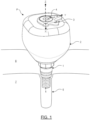
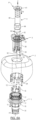
- the healing abutment P further comprises a reference member 3 defining a reference frame oriented X, Y, Z with several dimensions.
- the reference member 3 is on the one hand configured to cooperate with the foot 1 in order to define a plurality of elementary positions of the reference frame oriented X, Y, Z relative to the foot 1 along the Z axis and on the other hand mounted on the upper head part in order to allow at least one optimal elementary position to be selected from the plurality of elementary positions according to the determined shape of the upper head part.
- the terms “inner” and “outer” are defined radially relative to the Z axis and the terms “lower” and “upper” are defined relative to the vertical Z axis, oriented from the foot 1 towards the head 2.
- the foot 1 extends along the Z axis and comprises a lower foot part 10, an upper foot part 11 and a foot cavity 12 vertically passing through the lower foot part 10 and the upper foot part 11 for the passage of the clamping screw 4.
- the lower part of the foot 10 and the upper part of the foot 11 are separated by a crown 13 of axis Z.
- the crown 13 extends in radial projection relative to the axis Z so as to serve as an axial support for the head 2, that is to say as a stop, and to allow its correct axial positioning along the axis Z.
- the crown 13 has the advantage of being compact, it goes without saying that it could be replaced by any support element or even that the lower part of the foot 10 and the upper part of the foot 11 could be in direct contact.
- the crown 13 has a flat upper surface to cooperate with the head 2 in a stable manner.
- the crown 13 has a truncated lower surface, increasing from bottom to top along the Z axis, so as to adapt to the shape of the gum.
- the lower foot part 10 comprises a foot rod 14 having a surface of revolution of axis Z which is threaded, as well as a connecting ring 15 mounted above the foot rod 14 relative to the axis Z, of polygonal shape, defining in this example eight faces. Thanks to the foot rod 14 and the connecting ring 15, the lower foot part 10 is configured to ensure the connection between the healing abutment P and the implant 5.
- the foot rod 14 is configured to cooperate with the thread of the implant housing so as to screw the foot 1 onto the implant 5 while the connecting ring 15 is configured to cooperate with a polygonal outer wall of the implant housing so as to prevent unscrewing of the foot 1 relative to the implant 5, known to those skilled in the art under the term "anti-rotation system".
- the connecting ring 15 comprises eight faces but it goes without saying that the number of faces could be different. Furthermore, it goes without saying that the connecting ring 15 could be any anti-rotation system, or even that there might not be any anti-rotation system.
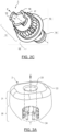
- the upper part of the foot 11 comprises a first fitting member 17 comprising a plurality of radial teeth relative to the Z axis configured to cooperate with a second fitting member of the head 2, in the form of radial notches.
- the first fitting member 17 and the second fitting member make it possible to angularly adjust the mounting of the head 2 on the foot 1.
- the head 2 can be mounted in different possible elementary positions on the foot 1.
- Such fitting members 17 also act as an anti-rotation system, preventing any possible rotational movement between the foot 1 and the head 2 once mounted.
- the number of radial teeth is twenty-four, providing fine angular adjustment.
- the head 2 can be positioned in twenty-four different elementary positions and thus adapt precisely to the available space left by the missing tooth in the patient's mouth.
- the number of radial teeth could be lower, the fineness of the angular adjustment then being less, within the lower limit of eight radial teeth.
- the number of radial teeth could also be higher, however the gain provided would be barely visible and would superfluously increase the complexity of the first fitting member 17.
- the radial teeth are in the form of triangular prisms with an axis Z, allowing easy mounting of the head 2 on the foot 1, but it goes without saying that the radial teeth could take a different form, such as a cylindrical form with a rectangular base.
- the upper head part 11 further comprises a third nesting member 16 mounted above the first nesting member 17 along the Z axis and comprising axial teeth of the Z axis so as to be able to mount the reference member 3 on the foot 1.
- the third nesting member 16 also acts as an anti-rotation system, preventing any possible rotational movement between the reference member 3 and the foot 1.
- the number of axial teeth amounts to four, offering four possible elementary positions for the reference member 3. It goes without saying that the number of axial teeth could be different, preferably equal to three to facilitate the positioning of the reference member 3, as illustrated in the Figure 2C .
- the axial teeth are in the form of cylinders with a rectangular base of axis Z, allowing easy mounting of the head 2 on the foot 1, but it goes without saying that the axial teeth could take a different form.
- foot 1 makes it possible to define precise angular orientations with respect to implant 5, head 2 and reference organ 3.
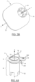
- the head 2 has a peripheral shape Z and comprises a lower head part 20, an upper head part 21 and a head cavity 23 passing through the lower head part 20 and the upper head part 21 for the passage of the clamping screw 4.
- the lower head portion 20 comprises a conical outer wall configured to promote healing of the gum following a concave profile around the conical outer wall, such that once the prosthetic tooth is placed, the interface between the prosthetic tooth and the gum is natural and aesthetic.
- the conicity of the outer wall of the lower head portion 20 depends on the missing tooth to be replaced, depending on whether it is an incisor, a canine, a premolar or a molar as examples.
- the outer wall is in continuity with the crown 13 of the foot 1.
- the head 2 forms a healing prosthetic tooth configured to have substantially the shape of the prosthetic tooth to be fitted.
- the addition of a temporary prosthetic tooth is therefore not necessary since the head 2 provides this function in addition to that of healing the gum.
- the upper head portion 21 comprises a rounded peripheral edge 22 for aesthetic purposes and to prevent the edge from being sharp and from being able to injure the patient's mouth.
- the lower head portion 20 comprises a second nesting member 24 comprising a plurality radial notches.
- a second interlocking member 24 is configured to cooperate with the first interlocking member 17 of the foot 1, so as to mount the head 2 on the foot 1 and to prevent a relative rotational movement between said head 2 and said foot 1.
- the number of radial notches of the second interlocking member 24 is equal to that of the first interlocking member 17, for easy assembly.
- the shape of the radial notches is complementary to the shape of the radial teeth of the first interlocking member 17, for easy assembly.
- the number of radial notches of the second interlocking member 24 and their shape may not be complementary to the radial teeth of the first interlocking member 17.
- Head 2 can thus be positioned ergonomically on foot 1.
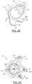
- the reference member 3 comprises a peripheral body 30 of axis Z, a neck 31 mounted on the body 30 and a reference cavity 32 of axis Z passing through the body 30 and the neck 31 for the passage of the clamping screw 4.
- the body 30 is configured to cooperate with the upper foot part 11.
- the neck 31 is configured to be mounted on the upper head part 21 and define the X, Y, Z reference.
- the neck 31 extends in a plane transverse to the Z axis.
- the cooperation of the body 30 and the upper part of the foot 11 makes it possible to link the angular positioning of the foot 1 to that of the reference member 3 and in particular to that of the neck 31 which is the visible part of the reference member 3 once the healing pillar P has been mounted.
- the orientation of the X, Y, Z reference frame defined by the neck 31 is that of the foot 1 which avoids having to dismantle the healing pillar P when taking impressions.
- the mounting of the neck 31 on the upper part of the head 21 also makes it possible to define the angular position of the head 2 in the reference frame oriented X, Y, Z.
- the reference member 3 and the head 2 make it possible in cooperation to fully determine the definitive prosthetic tooth.
- the reference cavity 32 also makes it possible to secure the reference member 3 to the healing pillar P.
- the body 30 is cylindrical with a circular section and has a diameter smaller than that of the head cavity 23 so as to be able to be inserted into said head cavity 23. Furthermore, the body 30 comprises a fourth fitting member 33 configured to cooperate with the third fitting member 16 of the foot 1, so as to mount the reference member 3 on the foot 1 and to prevent any relative rotational movement between said reference member 3 and said foot 1.
- the fourth fitting member 33 comprises axial notches. The number of axial notches of the fourth fitting member 33 is equal to that of axial teeth of the third fitting member 16, for easy assembly.
- the fourth nesting organ 33 thus comprises four axial notches to cooperate with the fourth fitting member 16 of the Figure 2B .
- the fourth nesting member 33 comprises three axial notches for cooperating with the fourth nesting member 16 of the Figure 2C .
- the shape of the axial notches is complementary to the axial teeth of the third interlocking member 16, for easy assembly.
- the number of axial notches of the fourth interlocking member 33 and their shape may not be complementary to the axial teeth of the third interlocking member 16.
- the neck 31 comprises a projecting portion 37 extending radially relative to the Z axis and the radial direction of which defines one of the directions of the X, Y, Z reference frame.
- the projecting portion 37 extends over a projecting radial length L37 greater than 2 mm, preferably greater than or equal to 3 mm so as to indirectly indicate an orientation of the foot 1.
- the projecting radial length L37 is less than 5 mm, so as to limit the bulk.
- Such a projecting radial length L37 also makes it possible to prevent the projecting portion 37 from extending in projection relative to the head 2, which would cause discomfort for the patient and complicate the assembly of the manufacturing abutment P.
- the projecting portion 37 is axially aligned with one of the axial notches of the fourth fitting member 33 for the sake of simplicity in defining the X, Y, Z reference, but it goes without saying that this might not be the case.
- the neck 31 comprises three projecting portions 37, 39A, 39B each aligned with an axial notch of the fourth fitting member 33.
- a single projecting portion 37 is sufficient to define the X, Y, Z reference, but the other projecting portions 39A, 39B make it possible to define the X, Y, Z reference with greater finesse, in order to be able to determine the prosthetic tooth as precisely as possible.
- the number of projecting portions is arbitrary, although a number greater than 3 would increase the bulk unnecessarily.
- each of the projecting portions 37, 39A, 39B also has a different projecting radial length L37 in order to be able to simply distinguish the projecting portion 37 from the others. It goes without saying, however, that the projecting portions 37, 39A, 39B could have the same projecting radial length L37.
- the projecting portions 37, 39A, 39B of the neck 31 are in the form of reference fingers 34, 35, 36, preferably rounded at their end so as not to bother the patient when touched.
- the projecting portions 37, 39A, 39B could have any different shape.
- the neck 31 could have a polygonal section of which the vertices form the projecting portions 37, 39A, 39B.
- the number of vertices could be equal to the number of axial notches of the fourth nesting member 33.
- the projecting portions 37, 39A, 39B could also have a different shape from each other in order to distinguish them.
- the neck 31 further comprises a reduced portion 38 extending radially relative to the Z axis.
- the reduced portion 38 is advantageously configured to reduce the size of the reference member 3 over a given angular range.
- the implant is not positioned in the center of the space left by the missing tooth.
- the head 2 extends off-center relative to the Z axis, that is to say that the head cavity 23 is off-center relative to the head 2.
- the reference member 3 can in this case be mounted angularly so that the reduced portion 38 is advantageously located where the radial distance separating the head cavity 32 from the outer walls of the upper head part 21 is the smallest.
- the reduced portion 38 has a reduced radial length L38 reduced less than 3 mm, preferably less than or equal to 2 mm, in order to be effective even in the case of pronounced off-centering.
- the reduced radial length L38 is greater than 0.5 mm.
- the reduced portion 38 extends over an angular range ⁇ 38 around the Z axis greater than 90°, preferably greater than 150°, preferably still greater than 180°, in order to be effective even in the case of pronounced off-centering.
- the clamping screw 4 is subsequently described with reference to the figure 5 .
- the clamping screw 4 comprises a Z-axis rod 40 and a screw head 41 mounted on the rod 40.
- the rod 40 has a diameter configured to be smaller than that of the foot cavity 12, the head cavity 23, the reference cavity 32 and the implant housing.
- the rod 40 is configured to be inserted into the foot cavity 12, the head cavity 23, the reference cavity 32 and the implant housing, so as to mount the healing abutment P on the implant.
- the rod 40 comprises a first threaded rod portion 42 configured to be screwed into the implant housing, a second rod portion 43 configured to extend into the lower head portion 10, a third rod portion 44 of diameter greater than the inner diameter of the crown 13 of the foot 1 and configured to extend into the upper head portion 11 and a fourth rod portion 45 configured to extend into the head cavity 23 and into the reference cavity 32. It goes without saying, however, that the rod 40 could comprise only one single rod portion or a selection of the aforementioned portions.
- the screw head 41 is flat so as to limit the size of the reference member 3 and comprises a head imprint 46 configured to receive a tool, such as a screwdriver, so as to screw the clamping screw 4 into the implant housing and tighten the assembly.
- a tool such as a screwdriver
- the head 2 is mounted on the foot 1 by a longitudinal translation movement T2 relative to the Z axis until the first interlocking member 17 and the second interlocking member 24 cooperate and the head 12 is in contact with the crown 13 of the foot 1.
- the angular orientation between the head 2 and the foot 1 is precisely defined.
- the head 2 rests on the crown 13 and is mounted fixed radially and tangentially relative to the Z axis on the foot 1.
- the head 2 is, however, mounted free in longitudinal translation along Z relative to the foot 1.
- the reference member 3 is mounted fixed radially and tangentially relative to the Z axis on the head 2 and mounted free in longitudinal translation along Z relative to said head 2.
- the angular orientation between the reference member 3 and the foot 1 is defined precisely.
- the clamping screw 4 is successively inserted into the reference cavity 32, into the head cavity 23, into the foot cavity 12 and into the implant housing by a longitudinal translation movement T4 relative to the Z axis and then by a rotation movement R4 about the Z axis so as to screw the first rod portion 42 into the implant housing.
- the rotation movement R4 is stopped when the third rod portion 44 is resting on the crown 13.
- the clamping screw 4 blocks the head 2 and the reference member 3 in the longitudinal direction relative to the Z axis. Furthermore, the clamping screw 4 is fixedly mounted in the implant housing.
Landscapes
- Health & Medical Sciences (AREA)
- Animal Behavior & Ethology (AREA)
- Dentistry (AREA)
- Epidemiology (AREA)
- Life Sciences & Earth Sciences (AREA)
- Oral & Maxillofacial Surgery (AREA)
- General Health & Medical Sciences (AREA)
- Public Health (AREA)
- Veterinary Medicine (AREA)
- Orthopedic Medicine & Surgery (AREA)
- Physics & Mathematics (AREA)
- Optics & Photonics (AREA)
- Dental Prosthetics (AREA)
- Prostheses (AREA)
Claims (9)
- Gingivaformer (P), der ausgelegt ist, um vor dem Einsetzen eines prothetischen Zahns in einem Implantat (5) angebracht zu werden, wobei der Gingivaformer (P) einen Fuß (1) und einen Kopf (2) umfasst, die gemäß einer Z-Achse ausgerichtet und durch eine Spannschraube (4) verbunden sind, die sich gemäß der Z-Achse erstreckt, wobei der Fuß (1) einen unteren Fußteil (10), der ausgelegt ist, um mit dem Implantat (5) zusammenzuwirken, und einen oberen Fußteil (11) umfasst, wobei der Kopf (2) einen unteren Kopfteil (20), der ausgelegt ist, um mit dem oberen Fußteil (11) derart zusammenzuwirken, dass der Kopf (2) auf dem Fuß (1) angebracht wird, und einen oberen Kopfteil (21) mit einer bestimmten Form umfasst, wobei der Gingivaformer (P) mindestens ein Referenzorgan (3) umfasst, das ein Koordinatensystem (X, Y, Z) definiert, dass gemäß mindestens zwei Dimensionen ausgerichtet und ausgelegt ist, um mit dem Fuß (1) zusammenzuwirken, um eine Vielzahl von Elementarpositionen des in Bezug auf den genannten Fuß (1) ausgerichteten Koordinatensystems (X, Y, Z) gemäß der Z-Achse zu definieren, wobei das Referenzorgan (3) beweglich und auf dem oberen Kopfteil (21) als Einsatz angebracht ist, um die Auswahl mindestens einer optimalen Elementarposition aus der Vielzahl von Elementarpositionen in Abhängigkeit von der bestimmten Form des oberen Kopfteils (21) zu ermöglichen.
- Gingivaformer (P) nach Anspruch 1, wobei das Referenzorgan (3) mindestens einen Hals (31) mit mindestens einem vorstehenden Abschnitt (37) umfasst, der sich radial in Bezug auf die Z-Achse derart erstreckt, dass das Koordinatensystem (X, Y, Z) definiert wird.
- Gingivaformer (P) nach Anspruch 2, wobei der vorstehende Abschnitt (37) in Form von mindestens einem Referenzfinger (34, 35, 36) vorliegt, der sich radial in Bezug auf die Z-Achse erstreckt.
- Gingivaformer (P) nach einem der Ansprüche 1 bis 3, wobei das Referenzorgan (3) mindestens einen Hals (31) umfasst, der mindestens einen reduzierten Abschnitt (38) umfasst, der sich radial in Bezug auf die Z-Achse erstreckt und eine reduzierte radiale Länge (L38) von unter 3 mm, vorzugsweise von unter oder gleich 2 mm, aufweist.
- Gingivaformer (P) nach Anspruch 4, wobei sich der reduzierte Abschnitt (38) über einen Winkelbereich (α38) um die Z-Achse erstreckt, der größer als 90°, vorzugsweise größer als 150°, ist.
- Gingivaformer (P) nach einem der Ansprüche 1 bis 5, wobei das Referenzorgan (3) einen durchgehenden Referenzhohlraum (32) in der Achse Z umfasst, in dem sich die Spannschraube (4) erstreckt.
- Gingivaformer (P) nach einem der Ansprüche 1 bis 6, wobei der obere Fußteil (11) mindestens ein erstes Einsteckorgan (17) umfasst, der untere Kopfteil (20) mindestens ein zweites Einsteckorgan (24) umfasst, das ausgelegt ist, um mit dem ersten Einsteckorgan (17) derart zusammenzuwirken, dass der Kopf (2) auf dem Fuß (1) angebracht wird, wobei das erste Einsteckorgan (17) mindestens acht radiale Zähne in Bezug auf die Z-Achse umfasst und das zweite Einsteckorgan (24) mindestens acht radiale Kerben umfasst, die ausgelegt sind, um mit den radialen Zähnen zusammenwirken, um eine Vielzahl von relativen Winkelpositionen zwischen dem Fuß (1) und dem Kopf (2) in Bezug auf die Z-Achse zu definieren.
- Gingivaformer (P) nach einem der Ansprüche 1 bis 7, wobei der Kopf (2) eine durchgehende Kopfvertiefung (23) in der Z-Achse aufweist, in der sich die Spannschraube (4) erstreckt.
- Anordnung aus einem Implantat (5) und einem Gingivaformer (P) nach einem der Ansprüche1 bis 8, wobei das Implantat (5) ein Befestigungsende, das ausgelegt ist, um am Kieferknochen (7) eines Patienten befestigt zu werden, und ein gingivales Ende umfasst, das ausgelegt ist, um sich in das Zahnfleisch (6) des Patienten zu erstrecken, und eine Implantataufnahme umfasst, die ein Innengewinde umfasst, wobei der untere Fußteil (10) des Gingivaformers (P) in der Implantataufnahme angebracht ist und die Spannschraube (4) des Gingivaformers (P) mit dem Innengewinde der Implantataufnahme zusammenwirkt.
Applications Claiming Priority (2)
| Application Number | Priority Date | Filing Date | Title |
|---|---|---|---|
| FR1911877A FR3102354B1 (fr) | 2019-10-23 | 2019-10-23 | Pilier de cicatrisation de la gencive autour d’un implant pour la pose d’une dent prothétique. |
| PCT/EP2020/079073 WO2021078628A1 (fr) | 2019-10-23 | 2020-10-15 | Pilier de cicatrisation de la gencive pour un implant dentaire |
Publications (3)
| Publication Number | Publication Date |
|---|---|
| EP4048190A1 EP4048190A1 (de) | 2022-08-31 |
| EP4048190C0 EP4048190C0 (de) | 2024-12-04 |
| EP4048190B1 true EP4048190B1 (de) | 2024-12-04 |
Family
ID=69375527
Family Applications (1)
| Application Number | Title | Priority Date | Filing Date |
|---|---|---|---|
| EP20789621.8A Active EP4048190B1 (de) | 2019-10-23 | 2020-10-15 | Gingivaformer für ein zahnimplantat |
Country Status (8)
| Country | Link |
|---|---|
| US (1) | US12336882B2 (de) |
| EP (1) | EP4048190B1 (de) |
| JP (1) | JP7591045B2 (de) |
| CN (1) | CN114599312B (de) |
| CA (1) | CA3153876A1 (de) |
| ES (1) | ES3006467T3 (de) |
| FR (1) | FR3102354B1 (de) |
| WO (1) | WO2021078628A1 (de) |
Families Citing this family (4)
| Publication number | Priority date | Publication date | Assignee | Title |
|---|---|---|---|---|
| US12257127B2 (en) | 2021-02-23 | 2025-03-25 | Biomet 3I, Llc | Dental implant system |
| CN115068139B (zh) * | 2022-07-22 | 2023-11-24 | 厦门市鑫达兴医疗科技有限公司 | 一种一体化多合一植牙组件 |
| TR2023002000A2 (tr) * | 2023-02-22 | 2023-03-21 | Sis Dental Implant Teknolojileri Sanayi Ve Ticaret Ltd Sirketi | İmplant tedavi̇si̇nde kullanilmasi i̇çi̇n di̇ş eti̇ i̇le uyumu arttirilmiş bi̇r i̇yi̇leşme başliği |
| US20260076783A1 (en) * | 2024-09-16 | 2026-03-19 | Evollution Ip Holdings, Inc. | Anatomical and scannable healing abutments |
Citations (1)
| Publication number | Priority date | Publication date | Assignee | Title |
|---|---|---|---|---|
| US20140205969A1 (en) * | 2012-11-20 | 2014-07-24 | Gerald M. Marlin | Universal Aligning Adaptor System and Methods |
Family Cites Families (34)
| Publication number | Priority date | Publication date | Assignee | Title |
|---|---|---|---|---|
| JPH05293123A (ja) * | 1992-04-22 | 1993-11-09 | Tdk Corp | 義 歯 |
| US5599185A (en) * | 1994-09-28 | 1997-02-04 | Greenberg Surgical Technologies, Llc | Dental implant healing abutment |
| CA2206163A1 (en) * | 1996-05-28 | 1997-11-28 | Norman H. Kwan | Dental implant system |
| WO2001085050A2 (en) * | 2000-05-11 | 2001-11-15 | Nobel Biocare Ab | Heal in-place abutment system |
| US7264469B2 (en) * | 2001-08-10 | 2007-09-04 | Juan Carlos Abarno | Split-implant and abutment system for dental reconstruction |
| CN101547660A (zh) * | 2006-11-22 | 2009-09-30 | 艾利泽·巴夏洛姆 | 用于植牙的配有斜球的多定位支持牙 |
| US20100233654A1 (en) * | 2007-10-19 | 2010-09-16 | Ki Bin Yang | Button for implant healing abutment and implant healing abutment having pressing part |
| US20110123948A1 (en) * | 2008-05-15 | 2011-05-26 | Uwe Hinrichsen | Two-part rotational dental implant abutment for use with existing implant bases |
| KR100948074B1 (ko) * | 2009-03-23 | 2010-03-16 | 주식회사 이노바이오써지 | 임플란트 보철 부품세트 및 상기 부품세트를 이용하여 지대주가 포함된 복제 석고모델의 제작방법 |
| ES2747818T3 (es) * | 2011-05-16 | 2020-03-11 | Biomet 3I Llc | Pilar temporal con combinación de características de escaneo y características de provisionalización |
| US20130196290A1 (en) | 2011-05-16 | 2013-08-01 | Biomet 3I, Llc | Healing Abutment Assembly With Combination Of Scanning Features |
| CA2853327C (en) * | 2011-10-26 | 2020-03-31 | Permatooth Inc. | Dental replacement mounting systems |
| US10568720B2 (en) * | 2012-01-10 | 2020-02-25 | Estetic Implant Solutions, LLC | Dental implants with markers for determining three-dimensional positioning |
| US10016260B2 (en) * | 2012-01-10 | 2018-07-10 | Mark H. Blaisdell | Anatomical healing abutments, kits, and methods |
| US20130203015A1 (en) * | 2012-01-17 | 2013-08-08 | James Falco | Gingival tissue contour device |
| KR101387573B1 (ko) * | 2012-06-15 | 2014-04-23 | (주)이비아이 | 임플란트용 어버트먼트 |
| KR101417980B1 (ko) * | 2013-08-26 | 2014-07-09 | 주식회사 디오 | 임플란트용 스캔 바디와 임플란트 어셈블리 |
| KR101419519B1 (ko) * | 2013-10-10 | 2014-08-13 | (주)교보테크 | 임플란트 어셈블리 |
| CN103550002A (zh) * | 2013-11-18 | 2014-02-05 | 大连三生科技发展有限公司 | 人工牙基台、人工牙多件式种植体系统及种植方法 |
| CN203555847U (zh) * | 2013-11-18 | 2014-04-23 | 大连三生科技发展有限公司 | 人工牙多件式种植体系统 |
| CN203591347U (zh) * | 2013-11-18 | 2014-05-14 | 大连三生科技发展有限公司 | 人工牙基台 |
| FR3042699B1 (fr) * | 2015-10-27 | 2021-02-19 | Euroteknika | Element de cicatrisation pour une restauration dentaire |
| WO2017085288A1 (en) * | 2015-11-20 | 2017-05-26 | Nobel Biocare Services Ag | Healing cap with scannable features |
| BR102016010184B1 (pt) * | 2016-05-05 | 2020-10-27 | Jjgc Indústria E Comércio De Materiais Dentários S.A. | conjunto protético e processo para produção do mesmo |
| EP3518817B1 (de) * | 2016-09-27 | 2020-12-16 | Valoc AG | System zur verbindung eines zahnersatzes mit einem zahnimplantat |
| US20190247154A1 (en) * | 2017-01-12 | 2019-08-15 | David J. Rallis | Gingival Tissue Former |
| DE102017007341A1 (de) * | 2017-01-13 | 2018-07-19 | Champions-Implants Gmbh | Anordnung, umfassend einen Implantatkörper und einen Gingivaformer |
| ES2946758T3 (es) * | 2017-03-20 | 2023-07-25 | Straumann Holding Ag | Ayuda al modelado de dos partes |
| KR102146836B1 (ko) * | 2017-06-15 | 2020-08-21 | 오스템임플란트 주식회사 | 힐링 어버트먼트 |
| GB201712780D0 (en) * | 2017-08-09 | 2017-09-20 | Neoss Ltd | Dental implant assembly |
| CN108309479A (zh) * | 2018-02-23 | 2018-07-24 | 中国人民解放军第四军医大学 | 一种牙种植体桥架基台组件 |
| CA3015903C (en) * | 2018-08-30 | 2023-11-28 | Michael Lowe | Dental insert |
| KR101966023B1 (ko) * | 2018-11-01 | 2019-04-04 | 이동섭 | 치과용 임플란트 |
| KR102204414B1 (ko) * | 2019-07-03 | 2021-01-18 | 오스템임플란트 주식회사 | 힐링 어버트먼트 |
-
2019
- 2019-10-23 FR FR1911877A patent/FR3102354B1/fr active Active
-
2020
- 2020-10-15 JP JP2022522621A patent/JP7591045B2/ja active Active
- 2020-10-15 US US17/769,302 patent/US12336882B2/en active Active
- 2020-10-15 WO PCT/EP2020/079073 patent/WO2021078628A1/fr not_active Ceased
- 2020-10-15 CA CA3153876A patent/CA3153876A1/fr active Pending
- 2020-10-15 EP EP20789621.8A patent/EP4048190B1/de active Active
- 2020-10-15 CN CN202080073996.2A patent/CN114599312B/zh active Active
- 2020-10-15 ES ES20789621T patent/ES3006467T3/es active Active
Patent Citations (1)
| Publication number | Priority date | Publication date | Assignee | Title |
|---|---|---|---|---|
| US20140205969A1 (en) * | 2012-11-20 | 2014-07-24 | Gerald M. Marlin | Universal Aligning Adaptor System and Methods |
Also Published As
| Publication number | Publication date |
|---|---|
| FR3102354A1 (fr) | 2021-04-30 |
| CN114599312B (zh) | 2024-08-23 |
| FR3102354B1 (fr) | 2022-10-21 |
| ES3006467T3 (en) | 2025-03-18 |
| EP4048190A1 (de) | 2022-08-31 |
| EP4048190C0 (de) | 2024-12-04 |
| JP2022553660A (ja) | 2022-12-26 |
| US12336882B2 (en) | 2025-06-24 |
| CA3153876A1 (fr) | 2021-04-29 |
| WO2021078628A1 (fr) | 2021-04-29 |
| JP7591045B2 (ja) | 2024-11-27 |
| CN114599312A (zh) | 2022-06-07 |
| US20240148477A1 (en) | 2024-05-09 |
Similar Documents
| Publication | Publication Date | Title |
|---|---|---|
| EP4048190B1 (de) | Gingivaformer für ein zahnimplantat | |
| FR2806903A1 (fr) | Prothese dentaire | |
| EP1613236B1 (de) | Verfahren zur reversiblen fixierung eines werkzeugs an einem implantierbaren element und vorrichtung zur durchführung dieses fixierverfahrens | |
| US20070148620A1 (en) | Dental implant device and correction device therefor | |
| FR2946523A1 (fr) | Pilier-implant dentaire | |
| FR2965473A1 (fr) | Implant endo-osseux a ancrage ameliore | |
| EP2544621A1 (de) | Anordnung eines zahnimplantats und prothesenelement | |
| FR3067588A1 (fr) | Ensemble de restauration dentaire | |
| EP2088957A2 (de) | Abdruckvorrichtung mit abdruck aufnehmender kappe für zahnprothese | |
| EP2685929B2 (de) | Zahnimplantat | |
| FR2808992A1 (fr) | Analogue de laboratoire pour prothese dentaire | |
| EP3478216B1 (de) | Abutment für die restaurative zahnmedizin | |
| WO1997037608A1 (fr) | Implant dentaire pour la realisation d'une implantation en un temps chirurgical | |
| FR2745998A1 (fr) | Support de prothese dentaire avec mecanisme anti-rotation | |
| BE1021495B1 (fr) | Dispositif prothetique de reconstruction dentaire | |
| FR3067589A1 (fr) | Element de cicatrisation dentaire | |
| FR3067587A1 (fr) | Ensemble de prise d'empreinte dentaire | |
| FR2931056A1 (fr) | Implant dentaire pour la realisation d'une implantation en un temps chirurgical | |
| WO2022195418A1 (fr) | Sous-ensemble dentaire pour la restauration prothetique unitaire d'une dent, et premier element destine a y etre associe | |
| EP0623010A1 (de) | Zahnimplantat | |
| WO1997037609A1 (fr) | Faux moignon destine a servir de base pour la realisation d'une prothese dentaire | |
| FR2695822A1 (fr) | Implant dentaire évolué et évolutif. | |
| FR2851454A1 (fr) | Ensemble comprenant un implant dentaire et un outil de mise en place de cet implant | |
| FR3079132A1 (fr) | Element prothetique temporaire comprenant un element fusible | |
| EP3311772A1 (de) | Gesamtheit der elemente zur herstellung einer zahnprothese |
Legal Events
| Date | Code | Title | Description |
|---|---|---|---|
| STAA | Information on the status of an ep patent application or granted ep patent |
Free format text: STATUS: UNKNOWN |
|
| STAA | Information on the status of an ep patent application or granted ep patent |
Free format text: STATUS: THE INTERNATIONAL PUBLICATION HAS BEEN MADE |
|
| PUAI | Public reference made under article 153(3) epc to a published international application that has entered the european phase |
Free format text: ORIGINAL CODE: 0009012 |
|
| STAA | Information on the status of an ep patent application or granted ep patent |
Free format text: STATUS: REQUEST FOR EXAMINATION WAS MADE |
|
| 17P | Request for examination filed |
Effective date: 20220413 |
|
| AK | Designated contracting states |
Kind code of ref document: A1 Designated state(s): AL AT BE BG CH CY CZ DE DK EE ES FI FR GB GR HR HU IE IS IT LI LT LU LV MC MK MT NL NO PL PT RO RS SE SI SK SM TR |
|
| DAV | Request for validation of the european patent (deleted) | ||
| DAX | Request for extension of the european patent (deleted) | ||
| STAA | Information on the status of an ep patent application or granted ep patent |
Free format text: STATUS: EXAMINATION IS IN PROGRESS |
|
| 17Q | First examination report despatched |
Effective date: 20230707 |
|
| GRAP | Despatch of communication of intention to grant a patent |
Free format text: ORIGINAL CODE: EPIDOSNIGR1 |
|
| STAA | Information on the status of an ep patent application or granted ep patent |
Free format text: STATUS: GRANT OF PATENT IS INTENDED |
|
| INTG | Intention to grant announced |
Effective date: 20240626 |
|
| GRAS | Grant fee paid |
Free format text: ORIGINAL CODE: EPIDOSNIGR3 |
|
| RAP3 | Party data changed (applicant data changed or rights of an application transferred) |
Owner name: CREADENT MONTAUBAN |
|
| RIN1 | Information on inventor provided before grant (corrected) |
Inventor name: CAMPS, JACQUES |
|
| GRAA | (expected) grant |
Free format text: ORIGINAL CODE: 0009210 |
|
| STAA | Information on the status of an ep patent application or granted ep patent |
Free format text: STATUS: THE PATENT HAS BEEN GRANTED |
|
| AK | Designated contracting states |
Kind code of ref document: B1 Designated state(s): AL AT BE BG CH CY CZ DE DK EE ES FI FR GB GR HR HU IE IS IT LI LT LU LV MC MK MT NL NO PL PT RO RS SE SI SK SM TR |
|
| REG | Reference to a national code |
Ref country code: CH Ref legal event code: EP |
|
| REG | Reference to a national code |
Ref country code: DE Ref legal event code: R096 Ref document number: 602020042586 Country of ref document: DE |
|
| REG | Reference to a national code |
Ref country code: IE Ref legal event code: FG4D Free format text: LANGUAGE OF EP DOCUMENT: FRENCH |
|
| U01 | Request for unitary effect filed |
Effective date: 20241217 |
|
| U07 | Unitary effect registered |
Designated state(s): AT BE BG DE DK EE FI FR IT LT LU LV MT NL PT RO SE SI Effective date: 20250110 |
|
| REG | Reference to a national code |
Ref country code: ES Ref legal event code: FG2A Ref document number: 3006467 Country of ref document: ES Kind code of ref document: T3 Effective date: 20250318 |
|
| PG25 | Lapsed in a contracting state [announced via postgrant information from national office to epo] |
Ref country code: HR Free format text: LAPSE BECAUSE OF FAILURE TO SUBMIT A TRANSLATION OF THE DESCRIPTION OR TO PAY THE FEE WITHIN THE PRESCRIBED TIME-LIMIT Effective date: 20241204 |
|
| PG25 | Lapsed in a contracting state [announced via postgrant information from national office to epo] |
Ref country code: NO Free format text: LAPSE BECAUSE OF FAILURE TO SUBMIT A TRANSLATION OF THE DESCRIPTION OR TO PAY THE FEE WITHIN THE PRESCRIBED TIME-LIMIT Effective date: 20250304 |
|
| PG25 | Lapsed in a contracting state [announced via postgrant information from national office to epo] |
Ref country code: GR Free format text: LAPSE BECAUSE OF FAILURE TO SUBMIT A TRANSLATION OF THE DESCRIPTION OR TO PAY THE FEE WITHIN THE PRESCRIBED TIME-LIMIT Effective date: 20250305 |
|
| PG25 | Lapsed in a contracting state [announced via postgrant information from national office to epo] |
Ref country code: RS Free format text: LAPSE BECAUSE OF FAILURE TO SUBMIT A TRANSLATION OF THE DESCRIPTION OR TO PAY THE FEE WITHIN THE PRESCRIBED TIME-LIMIT Effective date: 20250304 |
|
| PG25 | Lapsed in a contracting state [announced via postgrant information from national office to epo] |
Ref country code: SM Free format text: LAPSE BECAUSE OF FAILURE TO SUBMIT A TRANSLATION OF THE DESCRIPTION OR TO PAY THE FEE WITHIN THE PRESCRIBED TIME-LIMIT Effective date: 20241204 |
|
| PG25 | Lapsed in a contracting state [announced via postgrant information from national office to epo] |
Ref country code: PL Free format text: LAPSE BECAUSE OF FAILURE TO SUBMIT A TRANSLATION OF THE DESCRIPTION OR TO PAY THE FEE WITHIN THE PRESCRIBED TIME-LIMIT Effective date: 20241204 |
|
| PG25 | Lapsed in a contracting state [announced via postgrant information from national office to epo] |
Ref country code: IS Free format text: LAPSE BECAUSE OF FAILURE TO SUBMIT A TRANSLATION OF THE DESCRIPTION OR TO PAY THE FEE WITHIN THE PRESCRIBED TIME-LIMIT Effective date: 20250404 |
|
| PG25 | Lapsed in a contracting state [announced via postgrant information from national office to epo] |
Ref country code: SK Free format text: LAPSE BECAUSE OF FAILURE TO SUBMIT A TRANSLATION OF THE DESCRIPTION OR TO PAY THE FEE WITHIN THE PRESCRIBED TIME-LIMIT Effective date: 20241204 |
|
| PG25 | Lapsed in a contracting state [announced via postgrant information from national office to epo] |
Ref country code: CZ Free format text: LAPSE BECAUSE OF FAILURE TO SUBMIT A TRANSLATION OF THE DESCRIPTION OR TO PAY THE FEE WITHIN THE PRESCRIBED TIME-LIMIT Effective date: 20241204 |
|
| PLBE | No opposition filed within time limit |
Free format text: ORIGINAL CODE: 0009261 |
|
| STAA | Information on the status of an ep patent application or granted ep patent |
Free format text: STATUS: NO OPPOSITION FILED WITHIN TIME LIMIT |
|
| 26N | No opposition filed |
Effective date: 20250905 |
|
| U20 | Renewal fee for the european patent with unitary effect paid |
Year of fee payment: 6 Effective date: 20251028 |
|
| PGFP | Annual fee paid to national office [announced via postgrant information from national office to epo] |
Ref country code: GB Payment date: 20251022 Year of fee payment: 6 |
|
| PGFP | Annual fee paid to national office [announced via postgrant information from national office to epo] |
Ref country code: ES Payment date: 20251216 Year of fee payment: 6 |