EP4048193B1 - Verfahren zur herstellung einer kaltgussform und kaltgussform für die herstellung von formteilen, insbesondere zahnersatz - Google Patents
Verfahren zur herstellung einer kaltgussform und kaltgussform für die herstellung von formteilen, insbesondere zahnersatz Download PDFInfo
- Publication number
- EP4048193B1 EP4048193B1 EP20804152.5A EP20804152A EP4048193B1 EP 4048193 B1 EP4048193 B1 EP 4048193B1 EP 20804152 A EP20804152 A EP 20804152A EP 4048193 B1 EP4048193 B1 EP 4048193B1
- Authority
- EP
- European Patent Office
- Prior art keywords
- casting mold
- cold casting
- cavity
- opening
- cold
- Prior art date
- Legal status (The legal status is an assumption and is not a legal conclusion. Google has not performed a legal analysis and makes no representation as to the accuracy of the status listed.)
- Active
Links
Images



Classifications
-
- B—PERFORMING OPERATIONS; TRANSPORTING
- B29—WORKING OF PLASTICS; WORKING OF SUBSTANCES IN A PLASTIC STATE IN GENERAL
- B29C—SHAPING OR JOINING OF PLASTICS; SHAPING OF MATERIAL IN A PLASTIC STATE, NOT OTHERWISE PROVIDED FOR; AFTER-TREATMENT OF THE SHAPED PRODUCTS, e.g. REPAIRING
- B29C33/00—Moulds or cores; Details thereof or accessories therefor
- B29C33/38—Moulds or cores; Details thereof or accessories therefor characterised by the material or the manufacturing process
- B29C33/3842—Manufacturing moulds, e.g. shaping the mould surface by machining
-
- A—HUMAN NECESSITIES
- A61—MEDICAL OR VETERINARY SCIENCE; HYGIENE
- A61C—DENTISTRY; APPARATUS OR METHODS FOR ORAL OR DENTAL HYGIENE
- A61C13/00—Dental prostheses; Making same
- A61C13/20—Methods or devices for soldering, casting, moulding or melting
- A61C13/206—Injection moulding
-
- B—PERFORMING OPERATIONS; TRANSPORTING
- B29—WORKING OF PLASTICS; WORKING OF SUBSTANCES IN A PLASTIC STATE IN GENERAL
- B29C—SHAPING OR JOINING OF PLASTICS; SHAPING OF MATERIAL IN A PLASTIC STATE, NOT OTHERWISE PROVIDED FOR; AFTER-TREATMENT OF THE SHAPED PRODUCTS, e.g. REPAIRING
- B29C64/00—Additive manufacturing, i.e. manufacturing of three-dimensional [3D] objects by additive deposition, additive agglomeration or additive layering, e.g. by 3D printing, stereolithography or selective laser sintering
- B29C64/10—Processes of additive manufacturing
-
- A—HUMAN NECESSITIES
- A61—MEDICAL OR VETERINARY SCIENCE; HYGIENE
- A61C—DENTISTRY; APPARATUS OR METHODS FOR ORAL OR DENTAL HYGIENE
- A61C13/00—Dental prostheses; Making same
- A61C13/0003—Making bridge-work, inlays, implants or the like
- A61C13/0006—Production methods
-
- A—HUMAN NECESSITIES
- A61—MEDICAL OR VETERINARY SCIENCE; HYGIENE
- A61C—DENTISTRY; APPARATUS OR METHODS FOR ORAL OR DENTAL HYGIENE
- A61C13/00—Dental prostheses; Making same
- A61C13/0003—Making bridge-work, inlays, implants or the like
- A61C13/0006—Production methods
- A61C13/0019—Production methods using three dimensional printing
-
- A—HUMAN NECESSITIES
- A61—MEDICAL OR VETERINARY SCIENCE; HYGIENE
- A61C—DENTISTRY; APPARATUS OR METHODS FOR ORAL OR DENTAL HYGIENE
- A61C13/00—Dental prostheses; Making same
- A61C13/08—Artificial teeth; Making same
-
- A—HUMAN NECESSITIES
- A61—MEDICAL OR VETERINARY SCIENCE; HYGIENE
- A61C—DENTISTRY; APPARATUS OR METHODS FOR ORAL OR DENTAL HYGIENE
- A61C13/00—Dental prostheses; Making same
- A61C13/08—Artificial teeth; Making same
- A61C13/083—Porcelain or ceramic teeth
-
- A—HUMAN NECESSITIES
- A61—MEDICAL OR VETERINARY SCIENCE; HYGIENE
- A61C—DENTISTRY; APPARATUS OR METHODS FOR ORAL OR DENTAL HYGIENE
- A61C13/00—Dental prostheses; Making same
- A61C13/20—Methods or devices for soldering, casting, moulding or melting
-
- A—HUMAN NECESSITIES
- A61—MEDICAL OR VETERINARY SCIENCE; HYGIENE
- A61C—DENTISTRY; APPARATUS OR METHODS FOR ORAL OR DENTAL HYGIENE
- A61C5/00—Filling or capping teeth
- A61C5/70—Tooth crowns; Making thereof
- A61C5/77—Methods or devices for making crowns
-
- B—PERFORMING OPERATIONS; TRANSPORTING
- B29—WORKING OF PLASTICS; WORKING OF SUBSTANCES IN A PLASTIC STATE IN GENERAL
- B29C—SHAPING OR JOINING OF PLASTICS; SHAPING OF MATERIAL IN A PLASTIC STATE, NOT OTHERWISE PROVIDED FOR; AFTER-TREATMENT OF THE SHAPED PRODUCTS, e.g. REPAIRING
- B29C33/00—Moulds or cores; Details thereof or accessories therefor
- B29C33/38—Moulds or cores; Details thereof or accessories therefor characterised by the material or the manufacturing process
-
- B—PERFORMING OPERATIONS; TRANSPORTING
- B29—WORKING OF PLASTICS; WORKING OF SUBSTANCES IN A PLASTIC STATE IN GENERAL
- B29C—SHAPING OR JOINING OF PLASTICS; SHAPING OF MATERIAL IN A PLASTIC STATE, NOT OTHERWISE PROVIDED FOR; AFTER-TREATMENT OF THE SHAPED PRODUCTS, e.g. REPAIRING
- B29C33/00—Moulds or cores; Details thereof or accessories therefor
- B29C33/38—Moulds or cores; Details thereof or accessories therefor characterised by the material or the manufacturing process
- B29C33/3835—Designing moulds, e.g. using CAD-CAM
-
- B—PERFORMING OPERATIONS; TRANSPORTING
- B29—WORKING OF PLASTICS; WORKING OF SUBSTANCES IN A PLASTIC STATE IN GENERAL
- B29C—SHAPING OR JOINING OF PLASTICS; SHAPING OF MATERIAL IN A PLASTIC STATE, NOT OTHERWISE PROVIDED FOR; AFTER-TREATMENT OF THE SHAPED PRODUCTS, e.g. REPAIRING
- B29C64/00—Additive manufacturing, i.e. manufacturing of three-dimensional [3D] objects by additive deposition, additive agglomeration or additive layering, e.g. by 3D printing, stereolithography or selective laser sintering
- B29C64/10—Processes of additive manufacturing
- B29C64/165—Processes of additive manufacturing using a combination of solid and fluid materials, e.g. a powder selectively bound by a liquid binder, catalyst, inhibitor or energy absorber
-
- B—PERFORMING OPERATIONS; TRANSPORTING
- B29—WORKING OF PLASTICS; WORKING OF SUBSTANCES IN A PLASTIC STATE IN GENERAL
- B29C—SHAPING OR JOINING OF PLASTICS; SHAPING OF MATERIAL IN A PLASTIC STATE, NOT OTHERWISE PROVIDED FOR; AFTER-TREATMENT OF THE SHAPED PRODUCTS, e.g. REPAIRING
- B29C64/00—Additive manufacturing, i.e. manufacturing of three-dimensional [3D] objects by additive deposition, additive agglomeration or additive layering, e.g. by 3D printing, stereolithography or selective laser sintering
- B29C64/30—Auxiliary operations or equipment
- B29C64/386—Data acquisition or data processing for additive manufacturing
- B29C64/393—Data acquisition or data processing for additive manufacturing for controlling or regulating additive manufacturing processes
-
- B—PERFORMING OPERATIONS; TRANSPORTING
- B22—CASTING; POWDER METALLURGY
- B22F—WORKING METALLIC POWDER; MANUFACTURE OF ARTICLES FROM METALLIC POWDER; MAKING METALLIC POWDER; APPARATUS OR DEVICES SPECIALLY ADAPTED FOR METALLIC POWDER
- B22F10/00—Additive manufacturing of workpieces or articles from metallic powder
- B22F10/10—Formation of a green body
- B22F10/18—Formation of a green body by mixing binder with metal in filament form, e.g. fused filament fabrication [FFF]
-
- B—PERFORMING OPERATIONS; TRANSPORTING
- B22—CASTING; POWDER METALLURGY
- B22F—WORKING METALLIC POWDER; MANUFACTURE OF ARTICLES FROM METALLIC POWDER; MAKING METALLIC POWDER; APPARATUS OR DEVICES SPECIALLY ADAPTED FOR METALLIC POWDER
- B22F10/00—Additive manufacturing of workpieces or articles from metallic powder
- B22F10/20—Direct sintering or melting
-
- B—PERFORMING OPERATIONS; TRANSPORTING
- B29—WORKING OF PLASTICS; WORKING OF SUBSTANCES IN A PLASTIC STATE IN GENERAL
- B29C—SHAPING OR JOINING OF PLASTICS; SHAPING OF MATERIAL IN A PLASTIC STATE, NOT OTHERWISE PROVIDED FOR; AFTER-TREATMENT OF THE SHAPED PRODUCTS, e.g. REPAIRING
- B29C33/00—Moulds or cores; Details thereof or accessories therefor
- B29C33/38—Moulds or cores; Details thereof or accessories therefor characterised by the material or the manufacturing process
- B29C33/3842—Manufacturing moulds, e.g. shaping the mould surface by machining
- B29C2033/385—Manufacturing moulds, e.g. shaping the mould surface by machining by laminating a plurality of layers
-
- B—PERFORMING OPERATIONS; TRANSPORTING
- B33—ADDITIVE MANUFACTURING TECHNOLOGY
- B33Y—ADDITIVE MANUFACTURING, i.e. MANUFACTURING OF THREE-DIMENSIONAL [3D] OBJECTS BY ADDITIVE DEPOSITION, ADDITIVE AGGLOMERATION OR ADDITIVE LAYERING, e.g. BY 3D PRINTING, STEREOLITHOGRAPHY OR SELECTIVE LASER SINTERING
- B33Y10/00—Processes of additive manufacturing
-
- B—PERFORMING OPERATIONS; TRANSPORTING
- B33—ADDITIVE MANUFACTURING TECHNOLOGY
- B33Y—ADDITIVE MANUFACTURING, i.e. MANUFACTURING OF THREE-DIMENSIONAL [3D] OBJECTS BY ADDITIVE DEPOSITION, ADDITIVE AGGLOMERATION OR ADDITIVE LAYERING, e.g. BY 3D PRINTING, STEREOLITHOGRAPHY OR SELECTIVE LASER SINTERING
- B33Y50/00—Data acquisition or data processing for additive manufacturing
- B33Y50/02—Data acquisition or data processing for additive manufacturing for controlling or regulating additive manufacturing processes
-
- B—PERFORMING OPERATIONS; TRANSPORTING
- B33—ADDITIVE MANUFACTURING TECHNOLOGY
- B33Y—ADDITIVE MANUFACTURING, i.e. MANUFACTURING OF THREE-DIMENSIONAL [3D] OBJECTS BY ADDITIVE DEPOSITION, ADDITIVE AGGLOMERATION OR ADDITIVE LAYERING, e.g. BY 3D PRINTING, STEREOLITHOGRAPHY OR SELECTIVE LASER SINTERING
- B33Y70/00—Materials specially adapted for additive manufacturing
- B33Y70/10—Composites of different types of material, e.g. mixtures of ceramics and polymers or mixtures of metals and biomaterials
-
- B—PERFORMING OPERATIONS; TRANSPORTING
- B33—ADDITIVE MANUFACTURING TECHNOLOGY
- B33Y—ADDITIVE MANUFACTURING, i.e. MANUFACTURING OF THREE-DIMENSIONAL [3D] OBJECTS BY ADDITIVE DEPOSITION, ADDITIVE AGGLOMERATION OR ADDITIVE LAYERING, e.g. BY 3D PRINTING, STEREOLITHOGRAPHY OR SELECTIVE LASER SINTERING
- B33Y80/00—Products made by additive manufacturing
-
- Y—GENERAL TAGGING OF NEW TECHNOLOGICAL DEVELOPMENTS; GENERAL TAGGING OF CROSS-SECTIONAL TECHNOLOGIES SPANNING OVER SEVERAL SECTIONS OF THE IPC; TECHNICAL SUBJECTS COVERED BY FORMER USPC CROSS-REFERENCE ART COLLECTIONS [XRACs] AND DIGESTS
- Y02—TECHNOLOGIES OR APPLICATIONS FOR MITIGATION OR ADAPTATION AGAINST CLIMATE CHANGE
- Y02P—CLIMATE CHANGE MITIGATION TECHNOLOGIES IN THE PRODUCTION OR PROCESSING OF GOODS
- Y02P10/00—Technologies related to metal processing
- Y02P10/25—Process efficiency
Definitions
- the invention relates to a method for producing a cold casting mold for producing molded parts, in particular dental molded parts from a mixing compound, wherein the cold casting mold is additively constructed from a starting material using an additive material construction method, in particular a 3D printing method using a 3D printer, with a cavity that geometrically corresponds to the molded part, in particular dental molded part, using a digital data set based on a spatial model of the oral cavity of a patient and at least one first opening leading into the cavity for filling with the mixing compound.
- an additively constructed cold casting mold for a method for producing molded parts, in particular dental molded parts from a sinterable or light-curing mixing compound is also disclosed.
- CAD/CAM computer-aided processes
- dental molded parts in particular dental prostheses such as crowns and bridges, but also dental implants and prostheses or parts relevant to orthodontics such as brackets, are also produced using computer-aided processes (CAD/CAM) in many dental practices and dental laboratories.
- CAD/CAM computer-aided processes
- a digital, spatial model of a patient's oral cavity is created.
- the required dental prosthesis is planned using software and the data set created is transmitted, for example, to a milling machine that mills the finished dental prosthesis out of a blank.
- the blanks are usually produced using a cold casting process, in which a mixing mass is first produced from a ceramic powder or metal powder suitable for dental technology.
- a pasty mass, a slip, a suspension or even a "dry” powder filling can be used as a mixing mass.
- a process for producing dental prostheses from dental metal powder is known from the EP 2 470 113 B1 This involves mixing CrCo dental metal powder into a slip, pouring it cold into a mold and drying it there.
- a binding agent added to the slip gives it sufficient dimensional stability after drying, so that the dried slip can be removed from the cold casting mold as a green part. and milled into the desired spatial shape using the milling machine based on the transmitted digital data set.
- the final (dense) sintering gives the denture the required hardness and density.
- the material properties required for approval as dental molded parts are firmly defined by national and/or international standards.
- Such cold casting processes are only suitable for the production of blanks.
- the fine, complex shapes of the actual denture are then milled out of the blank by machining.
- Gauges for metal or ceramic slips for dental technology are state of the art and can be found, for example, in the publications EP1658018 B1 , EP1047355 B1 , WO 2013007684 A , EP1558170 B1 and EP1885278 B1 Information on their conditioning can be found in the printed publications DE 10 2005 023 727 B4 and DE19801534 A1
- the implementation of the final dense sintering is also sufficiently described in the state of the art, corresponding processes and sintering furnaces can be EP 2765950 B1 , EP 2844412 A1 , WO2011020688 A1 be taken.
- document CN106175946A1 describes a method and an apparatus for producing a dental prosthesis.
- the method comprises the steps of: preparing a dental prosthesis model according to the shape of the patient's teeth, forming an injection molding cavity in the same shape as that of the dental prosthesis model in a mold, forming an injection molding hole and an exhaust hole connected to the injection molding cavity, injecting molten raw materials into the injection molding cavity through the injection molding hole, and removing the molten raw materials after cooling and molding to obtain a dental prosthesis.
- the digital, spatial model of the oral cavity is also used for the production of temporary dentures made of plastic.
- the data set created for the denture is sent to a 3D printer, which builds the temporary denture layer by layer from plastic starting material using an additive material build-up process (3D printing).
- Additive material building processes such as SLM (selective laser melting) are well known.
- Extrusion processes such as FDM (Fused Deposition Molding) and FFF (Fused Filament Fabrication).
- Additive material construction processes that use the light-curing properties of the starting materials are also known, such as: SLA or STL (Stereolithography), DLP (Digital Light Processing), LCM (Lithography-based Ceramic Manufacturing).
- the digital, spatial data of the oral cavity are to be used to produce complexly shaped and densely sintered dental prostheses with a 3D printer
- a self-destructing mold is to be printed using a 3D printer.
- the starting material for the printing process is a powder mixture of two components, a sinterable aluminum powder and a powdered binder with a high coefficient of thermal expansion (CTE).
- the printed mold is filled with a sinterable, dry zirconia powder fill as a mixing mass.
- the mold is then closed with a lid printed from the same material in order to press the mold together with the zirconia powder fill inside it isostatically at a pressure of 400 MPa.
- the decisive factor in this process is that the powder fill is free of binders in order to enable even pressing.
- the powder fill is compacted together with the mold and then sintered without removing the mold. During sintering, the binding agents contained in the mold expand, causing the mold to burst.
- the sintering temperature of the mold In order for the finished sintered molded part to be released from the mold, the sintering temperature of the mold must be higher than the sintering temperature of the powder bed.
- the disadvantages of the disclosed process are, on the one hand, the high costs associated with 3D printing of the ceramic starting material and isostatic pressing at extremely high pressures of 400 MPa.
- the use of a ceramic starting material with a sintering temperature higher than that of the powder bed is crucial for the process described.
- the possible applications of the process are also limited.
- the mixing compound used must be free of binding agents in order to achieve uniform pressing.
- compacting pressing processes especially isostatic pressing, in which the pressure is to act evenly on the molded part from all sides, are not suitable for mixing compounds with a moisture content of more than 7%. Liquids are almost incompressible. To carry out isostatic pressing, the powder must be completely enclosed within the mold, which is closed with the lid. For this reason, any moisture contained in the mixing mass cannot escape.
- the object of the present invention is therefore to provide an additively constructed, in particular 3D-printed cold casting mold, which enables a more cost-effective and mass-producible production of dental molded parts with complicated anatomical shapes, colors and light-refracting surface structures, such as crowns, bridges, jaw implants, abutments, prostheses, etc., compared to the prior art.
- the possible uses are to be expanded.
- the use of a wide variety of mixing masses, made of sinterable and non-sinterable, metallic and/or ceramic materials or of plastic, either in dry powder form or as a slip, suspension or pasty mass, is made possible.
- a method for producing a cold casting mold of the type described in more detail at the outset is characterized in that the cold casting mold is additively constructed with at least one second opening leading into and/or out of the cavity for discharging gases, in particular air inclusions, and/or liquids, in particular diluents.
- At least one second opening is formed which, like the first opening, flows into or out of the cavity in a fluid-conducting manner.
- first opening and/or the second opening in particular to drill them, after the additive construction of the cold casting mold has been completed.
- second opening for venting
- first opening for filling
- the second opening makes it possible to discharge fluids, i.e. gases and/or liquids, while the cold casting mold is being filled (comparable to a ventilation opening when pouring with a TetraPak ® ).
- fluids i.e. gases and/or liquids
- the at least one first opening and/or the at least one second opening remain unlocked, which allows fluids to escape.
- air pockets caused by filling the cold casting mold with the mixing compound can be discharged.
- liquids such as thinners contained in pasty, moist or slip-like mixing compounds or suspensions can also be discharged from the cavity of the cold casting mold, which allows the mixing compound to dry inside the cold casting mold.
- the cold casting mold additively constructed according to the method according to the invention can not only be used for mixing mass with any moisture content, the at least one second opening also allows ventilation when using a powder bed, which can be supported by shaking, for example.
- At least one wall of the cold casting mold delimiting the cavity is therefore additively constructed, completely or in regions, with a plurality of second openings opening into the cavity and penetrating this wall for discharging gases, in particular air inclusions, and/or liquids, in particular diluents.
- a sieve-like surface By penetrating one or more walls of the cold casting mold with a large number of adjacent second openings, a sieve-like surface can be formed which allows liquids and gases to pass through, but retains solids.
- the diameter of the respective second openings is preferably smaller than the particle size and/or the size of the particle agglomerates that form in the powder contained in the mixing mass, such as metal powder, ceramic or glass ceramic powder or plastic powder.
- the plurality of second openings are therefore also designed in the form of pores and/or capillaries that penetrate the wall, so that the wall has porous and/or hygroscopic properties completely or in regions.
- Such a design also has the advantage that moisture contained in the mixing compound is absorbed or sucked up by the adjacent, porous and/or hygroscopic wall and preferably transported out of the interior, towards the atmosphere surrounding the cold casting mold or away. This effect can be supported by increasing the ambient temperature surrounding the cold casting mold or other measures to reduce the humidity of the environment, thereby creating drier ambient air.
- the moisture absorption capacity of the porous and/or hygroscopic areas can be increased by using a suitable starting material.
- Other areas or structures of the cold casting mold, such as filling channels, compensation volumes or support structures, can be formed by selecting a different starting material with different properties, e.g. water solubility, color, transparency, etc.
- the cold casting mold can be additively constructed with a filling channel that is fluid-conductingly adjacent to the at least one first opening.
- the filling channel is preferably formed in one piece with the cold casting mold.
- the filling channel enables, in particular, pressurized filling of the cold casting mold, for example by injection molding.
- the filling channel is fluidically connected to at least one compensation volume for holding mixing mass.
- the compensation volume is also built up in one piece with the cold casting mold.
- the compensation volume acts as a type of reservoir and allows mixing compound to continue to flow or trickle down in order to compensate for the loss of volume caused by the escape of gases and/or liquids from the cavity via the at least one second opening.
- a faster and/or more uniform filling of the cavity of the cold casting mold can be realized according to an alternative variant of the invention by additively constructing the cold casting mold with two or more first openings, each opening into the cavity, for simultaneous or staggered filling with mixing compound.
- first openings By having two or more first openings provided for filling open into the cavity at different positions, it is possible, for example, to fill the cavity with different mixing compounds at different positions. If the additional first openings are not used for filling, they can function as second openings for discharging fluids.
- an organic material in particular an organic wax and/or a polymer and/or a plastic, as the starting material for the additive construction of the cold casting mold, so that the cold casting mold is plasticizable and/or thermally and/or thermochemically decomposable.
- Organic materials such as waxes and/or polymers and/or plastics are much simpler and therefore more cost-effective in additive material building processes such as in 3D printing.
- the heat resistance of plastics is comparatively low, so that the cold casting mold additively constructed from an organic material can be plasticized or even decomposed thermally and/or thermochemically, in particular by pyrolysis and/or combustion.
- a starting material with a lower melting point e.g. wax
- the organic starting material can contain small amounts of inorganic materials.
- inorganic additives it is common to add inorganic additives to plastics.
- the proportion of organic components is always higher than the proportion of inorganic components.
- the organic material used for the additive construction of the cold casting mold has a melting point and/or a decomposition temperature in a temperature range of 40°C to 300°C, preferably 60°C to 300°C.
- the melting temperature or melting temperature range of the cold casting mold is therefore below the melting and/or sintering temperature of the mixing masses usually used.
- the decomposition temperature i.e. the temperature at which thermal and/or thermochemical decomposition of the cold casting mold begins, is also below the melting and/or sintering temperature of the mixing mass used.
- the organic material used for the additive construction of the cold casting mold can be plasticized by the action of heat, in particular at a temperature in a temperature range of 35°C to 300°C, preferably 50°C to 300°C, and/or can be thermally decomposed by pyrolysis and/or thermochemically decomposed by combustion by the action of heat, in particular at a temperature in a temperature range of 200°C to 650°C.
- a material group with particularly Waxes, for example, are materials with low heat resistance.
- the thermal and/or thermochemical decomposition can preferably be continued completely and/or at high temperatures in a sintering temperature range of 1300°C to 2500°C, so that a residue-free or at least almost residue-free dissolution of the cold casting mold is made possible by the action of heat.
- mechanical destruction of the cold casting mold can already be provided during the additive material build-up process by additively building up at least one wall delimiting the cavity of the cold casting mold with a predetermined breaking point, in particular with a partially reduced wall thickness.
- the proposed manufacturing process is based on spatial, digital data, in particular of the oral cavity of a patient.
- the geometric shape data derived from this for molded parts, in particular for dental molded parts, are used directly in the additive material build-up process for the geometric design of the cavity of the cold casting mold.
- the digital data set for the geometric design of the cavity of the cold casting mold therefore preferably includes a sintering and/or curing-related volume shrinkage of the mixing compound.
- a corresponding volume shrinkage must be taken into account when the mixing compound hardens or solidifies and/or sinters, and the cavity of the cold casting mold must be formed with a correspondingly adapted (larger) initial geometry.
- a sintering shrinkage in a range of 25% to 50% for mixing compounds containing sol and nanozirconium oxide particles in a range of 50% to 95% and for mixing compounds containing metal powder a sintering shrinkage in a range of 8% to 25%, each based on the initial geometry, must be taken into account.
- a volume shrinkage of approximately 2% to 20% based on the initial geometry must be taken into account.
- a volume shrinkage in the range of 1% to 10% based on the initial geometry can also be taken into account for the production of the molded part.
- the cold casting mold produced using the method according to the invention enables cost-effective production of molded parts, in particular dental molded parts, from a wide variety of mixing materials.
- the cold casting mold according to the invention has at least one first opening opening into the cavity for filling with the mixing compound and is characterized by at least one second opening opening into the cavity for discharging gases, in particular air inclusions, and/or liquids, in particular diluents.
- the cold casting mold comprises an organic material, in particular an organic polymer or a plastic with a melting point and/or a decomposition temperature in a temperature range from 40°C to 300°C, in particular from 60°C to 300°C, so that the cold casting mold can be plasticized, in particular at a temperature in a temperature range from 35°C to 300°C, in particular from 50°C to 300°C, and/or can be thermally and/or thermochemically decomposed, in particular at a temperature in a temperature range from 200°C to 650°C.
- an organic material in particular an organic polymer or a plastic with a melting point and/or a decomposition temperature in a temperature range from 40°C to 300°C, in particular from 60°C to 300°C, so that the cold casting mold can be plasticized, in particular at a temperature in a temperature range from 35°C to 300°C, in particular from 50°C to 300°C, and/or can be thermally and/or thermochemically decomposed, in particular at
- the linear thermal expansion of the cold casting mold is advantageously at most 10%, preferably at most 3% and particularly preferably at most 0.8% based on its initial geometry, whereby the maximum thermal expansion of the cold casting mold at a temperature of less than or equal to 240°C, preferably less than or equal to 200°C, more preferably less than or equal to 150°C and particularly preferably less than or equal to 100°C.
- the coefficient of thermal expansion (CTE) of the mixing compound can be adjusted to the CTE of the cold casting mold by the proportions of polyelectrolytes and binders (polymers), taking into account the respective CTEs of the metal, ceramic or glass ceramic powder used, so that the cold casting mold and mixing compound are subject to a similar or identical thermal expansion.
- the mechanical stability of the mixing compound (in the green state) can be increased by increasing the proportion of binder.
- the cold casting mold has a Shore A hardness of at least 15 and/or Shore D of at least 10 and a modulus of elasticity of at least 5 MPa.
- the walls delimiting the cavity of the cold casting mold preferably each have a wall thickness of at least 0.01 mm.
- the Shore hardness is a material characteristic for elastomers and plastics and is defined in the standards DIN EN ISO 868, DIN ISO 7619-1 and ASTM D2240-00.
- the modulus of elasticity also known as tensile modulus or E-modulus, is determined for plastics in particular according to DIN EN ISO 527-1:2019-12.
- the mixing mass or different mixing masses can be marked with optical markers, in particular with food coloring.
- the filling of the cold casting mold can then be automatically monitored with a camera.
- the application possibilities of the cold casting mold can also be extended to light-curing mixing compounds, which are light-cured inside the cold casting mold in an appropriately adapted process for the production of molded parts, in particular dental molded parts.
- the object of the invention stated at the outset is consequently also achieved by a method for producing molded parts, in particular dental molded parts, from a sinterable mixing compound using a cold casting mold according to the invention and by a method for producing molded parts, in particular dental molded parts, from a light-curing mixing compound using a cold casting mold according to the invention according to one of the preceding embodiments.
- gases and/or liquids contained and/or enclosed in the mixing compound are discharged from the cavity via the at least one second opening.
- gases and/or liquids contained and/or enclosed in the mixing compound can also escape via the at least one first opening, which remains unlocked during the entire process.
- a manufacturing method is also published using a cold casting mold with at least two openings connected to the cavity in a fluid-conducting manner, wherein the cavity of the cold casting mold is filled via one, the first opening, and fluids contained in the mixing compound, such as diluents or fluids enclosed by the mixing compound, such as air inclusions, are discharged from the mixing compound or from the cavity at least via another, the second opening.
- fluids contained in the mixing compound such as diluents or fluids enclosed by the mixing compound, such as air inclusions
- the mixing mass is therefore in the form of a slip and/or pasty mass and contains a diluent, in particular water, wherein the mixing mass hardens in the cavity of the cold casting mold by drying and a liquid portion and/or moisture content of the mixing mass is discharged from the cold casting mold by means of the at least one or the plurality of second openings, in particular is removed from the mixing mass.
- a diluent in particular water
- the mixing mass comprises a metal powder, in particular a CrCo powder or a ceramic powder, in particular a zirconium oxide powder and/or an aluminum oxide powder or a glass ceramic powder, in particular a lithium disilicate powder and a binder, wherein the mixing mass hardens to green compact hardness in the cavity of the cold casting mold in a further development of this process design.
- Binders are known in many different forms from the state of the art and consist mainly of organic substances such as resins, surfactants, polyelectrolytes, polymers and/or waxes, which lead to a comparatively low melting point.
- the temperature resistance and/or heat resistance of the cold casting mold in particular the melting point and/or the decomposition temperature of the cold casting mold, is below the melting point of the binder and/or below the sintering temperature of the metal powder or the ceramic powder.
- the method involves the use of a thermally and/or thermochemically decomposable cold casting mold.
- the thermal and/or thermochemical decomposition of the cold casting mold is preferably carried out in a sintering furnace, whereby the cold casting mold is opened and placed in the sintering furnace together with the mixing mass contained therein.
- the decomposition of the cold casting mold can be initiated or carried out completely at a temperature in the range of 200°C to 650°C.
- the respective sintering temperatures of the ceramic powders or metal powders contained in the sinterable mixing masses are in a range between 1200°C and 2500°C, so that the cold casting mold is completely or almost completely thermally and/or thermochemically decomposed by the time the finished molded part, i.e. molded part sintered to its final hardness, is obtained, in particular a dental molded part.
- the cold casting mold can be removed gently and without damaging the molded part without additional work steps before or during the sintering process.
- An optional process step provides for pre-sintering the mixing mass before the actual sintering, in particular at a temperature in a temperature range of 650°C to 1300°C, in order to remove the binder components before the molded part is compacted to final hardness.
- the decomposition of the cold casting mold can be carried out pyrolytically under oxygen-free conditions.
- the cold casting mold is placed together with the mixing mass contained therein in a sintering furnace, which enables sintering under vacuum and/or a protective atmosphere.
- This process variant is particularly suitable for the production of metallic, dental molded parts, for example made of a CrCo alloy, in order to avoid damage to the molded part through oxidation.
- a different process variant also allows the cold casting mold to be decomposed by combustion under the supply of oxygen.
- thermal and/or thermochemical decomposition of the cold casting mold can be dispensed with.
- the cold casting mold is separated or detached from the mixing mass along one or more predetermined breaking points of the cold casting mold in order to obtain a molded part that is ready for use, in particular to obtain a dental molded part, such as a denture.
- the predetermined breaking points are preferably already formed during the manufacture of the cold casting mold, in particular they can be wall areas with a thinner wall thickness than the other wall areas.
- the cold casting mold can be "torn open" along the predetermined breaking points after the mixing compound has hardened and/or solidified and thus detached from the molded part.
- the mixing mass comprises an organic material, in particular a plastic or a plastic-based composite material, in particular a plastic-based hybrid composite material or nanohybrid composite material.
- organic material in particular a plastic or a plastic-based composite material, in particular a plastic-based hybrid composite material or nanohybrid composite material.
- Such composites have so far mostly been used in dental technology for fillings or temporary restorations.
- nanohybrid composite materials with a high filler content of fibers or particles, with a particle size in the nanometer range, that the material properties required for dental molded parts, such as dentures, in terms of hardness and impermeability can be achieved.
- the mixing compound hardens in the cavity of the cold casting mold through a chemical reaction, for example by means of a two-component binder.
- the chemical reaction can be started by the action of heat and/or moisture removal.
- the chemical reaction is particularly preferably triggered by the action of light, whereby the walls delimiting the cavity of the cold casting mold are transparent and/or permeable to UV radiation and the cold casting mold is irradiated with a light source, in particular a UV lamp.
- the mixing compound is cured in the cavity of the cold casting mold to the desired final hardness, i.e. the hardness of the finished molded part, before the cold casting mold is detached or removed.
- the cold casting mold in particular the walls of the cold casting mold that delimit the cavity, can be coated with a coating agent before filling with the mixing compound in order to avoid a frictional and/or material-locking connection between the cold casting mold and the mixing compound.
- the cavity of the cold casting mold is filled under pressure, whereby an internal pressure in the cavity is lower than a filling pressure with which the mixing mass is supplied to the cavity.
- a negative pressure compared to the environment or a vacuum can be generated within the cavity, whereby the mixing compound is "sucked" into the cavity.
- the vacuum or negative pressure is released so that liquids and/or gases can escape from the at least one second opening and/or the at least one first opening.
- the filling pressure then corresponds to the ambient pressure.
- the mixing compound can be injected into the cavity, for example by means of a pump, a screw conveyor or a simple syringe under pressure, with overpressure in a range of, for example, between 1.5 mbar and 10 bar, whereby liquids and gases can escape from the at least one second opening during filling.
- a well-known pressure filling process is, for example, the injection molding process.
- the mixing compound in the cavity of the cold casting mold hardens under the influence of heat.
- the cold casting mold filled with the mixing compound and opened is placed in a drying cabinet or climate cabinet or a sintering furnace and a temperature is set in a temperature range of 35°C to 120°C, preferably 50°C to 120°C.
- the air humidity can also be set to a desired value. For gentle, even and at the same time rapid drying, an air humidity in a range of 1% to a maximum of 50% has proven to be advantageous.
- the heat effect and, if necessary, reduced air humidity can accelerate the hardening and/or solidification of the mixing compound, for example in the case of a drying process.
- the atmosphere or ambient air in the environment i.e. in the drying cabinet or climate cabinet or in the sintering furnace, is dried, which means that moisture and/or liquid contained in the mixing compound is transported out of the cavity into the environment more quickly.
- This effect can have a significant influence on the drying times, especially when the walls of the cold casting mold are designed with a porous and/or hygroscopic surface that is penetrated by a large number of second openings in the form of pores and/or capillaries.
- the cold casting mold is plasticized after being filled with the mixing compound and preferably also after it has hardened in order to facilitate the detachment of the walls delimiting the cavity from the mixing compound contained therein, whereby the cold casting mold filled with the mixing compound is placed in a drying cabinet or climate cabinet or a sintering furnace and a temperature is set in a temperature range of 35°C to 300°C, preferably 45°C to 180°C.
- the material properties of organic materials or plastics can be used here. Before the melting point of the cold casting mold is reached, the organic material, in particular the plastic, begins to soften, which makes the cold casting mold plasticizable or plastically deformable. By blowing in compressed air in a targeted manner, the soft, deformable cold casting mold can be released from the preferably hardened mixing compound.
- a particularly fast and uniform filling can be achieved, for example, according to a variant of the process in which the cavity of the cold casting mold is filled with the mixing compound via several initial openings.
- mixing compounds consisting of two or more components can be filled into the cavity of the cold casting mold via two or more first openings in order to prevent, for example, premature (light-induced) hardening and/or solidification during filling.
- the cavity of the cold casting mold is filled via the plurality of first openings with respective mixing masses containing additives for coloring and/or for producing opacity for producing a molded part, in particular a dental molded part with areas of differing colors and/or opacity.
- the different mixing materials can contain different additives, which lead to the finished molded part being colored according to the standard color ring from Vita, Bad Sburgingen, A1 to A4, B1 to B4, C1 to C4 and D1 to D4.
- suitable coloring elements are Fe, Mn, Cr, Ni, Co, Pr, Ce, Eu, Gd, Nd, Yb, Tb, Er and Bi.
- the cold casting mold is manufactured according to one of the process variants of the manufacturing process for a cold casting mold described at the beginning.
- the Figures 1 and 2 each show a first embodiment of a cold casting mold 100 according to the invention, in a schematic perspective view and in a sectional view.
- the cold casting mold 100 is designed here, for example, in the form of a test specimen, the cavity 110 of which has geometric properties typical for dental molded parts 210, which lead to wall thicknesses of the molded part 210 in a range from 0.30 mm to 10 mm.
- the cavity 110 of the cold casting mold 100 is delimited by the outer walls 121 and the inner walls 122 of the cold casting mold 100, so that the finished molded part 210, e.g.
- a crown has an inner cavity 211 (see Figure 8 ) which, for example, corresponds to the shape of an abutment, whereby the crown can be placed on the abutment.
- the inner walls 122 form a cylindrical or truncated cone shape for this purpose.
- a first opening 111 opens into the cavity 110 and penetrates one of the outer walls 121 which is occlusal with respect to the dental molded part 210.
- the cavity 110 is filled with the mixing compound 200 via the first opening 111.
- the inner walls 122 are penetrated by a plurality of second openings 112 which, for example, enable fluids 205, 207 and/or air inclusions 208 contained in the mixing compound 200 to escape during filling.
- fluids 205, 207, 208 can optionally also escape via the first opening 111.
- the plurality of second openings 112 can, as shown here by way of example, penetrate an inner surface of the cavity 110 in a sieve-like manner.
- the plurality of second openings 112 could be designed in the manner of pores and/or capillaries and form a porous and/or hygroscopic surface.
- a filling channel 130 with a compensation volume 131 is connected to the first opening 111 in a fluid-conducting manner.
- Filling means 400 such as injection syringes 420, in particular low-pressure injection syringes (see Figure 15 ) or supply lines, such as hoses 410 (see Figure 6 ) to facilitate the filling of cavity 110 with mixing compound 200.
- the Compensating volume 131 serves as a type of reservoir for the mixing compound 200, so that the volume loss of fluids 205, 207, 208 escaping through the second openings 112 can be compensated by means of the mixing compound 200 held in the compensating volume 131.
- the cold casting mold 100 is manufactured in one piece with the filling channel 130 and the compensating volume 131.
- FIG 3 A schematic perspective view of a second embodiment of a cold casting mold 100 according to the invention is shown.
- the cold casting mold 100 corresponds to the Figures 1 and 2 shown first embodiment with the exception that the filling channel 130 is designed without the (optional) compensation volume 131 and a channel-like, second opening 112 opens integrally into the occlusal, outer wall 121.
- the filling channel 130 can optionally be realized in one piece or as an additional part of the cold casting mold (100) and opens with its first opening 111 into the cavity (110). In this variant, the first opening 111 passes concentrically through the second opening 112.
- a separate compensation volume 131 in particular as a component of a filling means 400, can be connected to the filling channel 130.
- a sectional view of a third embodiment of a cold casting mold 100 according to the invention with a total of five filling channels 130 can be seen in the Figure 4
- the filling channels 130 each open into the cavity 100 via first openings 111 passing through the occlusal, outer wall 121 of the cold casting mold 100.
- Each of the filling channels 130 is connected to an associated compensation volume 131 in a fluid-conducting manner.
- the cold casting mold 100 can optionally be filled with the same or different mixing compound 200 via one or more of the filling channels 130, with filling channels 130 not used for filling then functioning as respective second openings 112 and serving to discharge fluids 205, 207 and/or air inclusions 208 contained in the mixing compound 200.
- all filling channels 130 are used, a quick and particularly uniform filling of the cavity 110 of the cold casting mold 100 is possible.
- the Figure 5 a schematic perspective view of a fourth embodiment of a cold casting mold 100 according to the invention can be seen.
- the cold casting mold 100 has a total of five filling channels 130, which pass through the occlusal, outer wall 121 into the cavity 110 via first openings 111.
- One of the filling channels 130 is provided with a conveying and/or mixing means 132, here in the form of a screw conveyor.
- This filling channel 130 is designed with a larger cross-sectional area, in particular a larger diameter, than the four other filling channels 130.
- the conveying and/or mixing means 132 is inserted as an additional component into the filling channel 130, which is preferably designed in one piece with the cold casting mold 100.
- the conveying and/or mixing agent 132 can be additively formed directly in the interior of the filling channel 130 during the manufacture of the cold casting mold 100.
- the cold casting mold is according to the Figure 5 in a sectional view with additional, respective compensation volumes 131, which are connected to the respective filling channels 130 in a fluid-conducting manner.
- a filling means 400 is connected to the filling channel 130 containing the conveying and/or mixing means 132 via two hoses 420.
- Mixing mass 200 is fed to the cold casting mold 100 via the hoses 420.
- the embodiment shown here is particularly suitable for mixing masses 200 that are composed of two components, for example.
- the components can initially be fed separately to the filling channel 130 via the two hoses 420 and mixed with one another there by means of the conveying and/or mixing means 132 before the mixed mixing mass 200 enters the cavity 110 through the first opening 111.
- a fifth embodiment of a cold casting mold 100 according to the invention can be Figure 7 in a schematic side view.
- the cold casting mold 100 is formed in one piece with two wall reinforcements or projections 123, each in the form of a flange.
- the section of the corresponding outer wall 121 lying between the wall reinforcements 123 is made with a smaller wall thickness than the wall reinforcements 123 and therefore serves as a predetermined breaking point 124.
- the cold casting mold 100 can be "levered open" along the predetermined breaking point 124 in order to release the cold casting mold 100 from the mixing compound 200 hardened therein.
- the mixing compound 200 cured to the final hardness required for dental moldings 210, is the Figure 8 as a finished molded part 210, which was produced with the cold casting mold 100 designed as a test specimen.
- the molded part 210 has wall thicknesses in a range from 0.3 mm to 10 mm.
- a lower, apical section of the molded part 210 is formed with a recess 211, the shape of which corresponds to the shape of an abutment for placing a dental molded part 210, for example a crown.
- the inwardly facing walls of the recess 211 are provided with a knob-like surface 212.
- the knob-like surface 212 improves the hold between the dental molded part 210, for example a crown, and e.g. the abutment.
- FIG 9 is the cold casting mold 100 from the Figure 4 shown in a sectional view.
- the cavity 110 of the cold casting mold 100 is filled here with different mixing compounds 201, 202, 203, 204 via a filling means 400.
- the mixing compounds 201, 202, 203, 204 each contain additives that are suitable for coloring and/or creating opacity of the finished molded part 210.
- Each of the mixing compounds 201, 202, 203, 204 is preferably filled into the cavity 110 via its own filling channel 130 and the respective first opening 111 connected thereto.
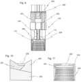
- the Figures 10 and 11 each show a schematic sectional view of a cavity 110 filled with different mixing compounds 201, 202, 203, 204.
- the lower, apical section of the cavity 110 can be filled with a third mixing compound 203, two external, occlusal sections with a first mixing compound 201 or a fourth mixing compound 204 and an occlusal section in between with a second mixing compound 202.
- the finished, dental molded part 210 After curing and/or solidifying to final hardness, the finished, dental molded part 210 then has areas or sections of different colors or tooth colors and/or different opacities or transparencies.
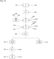
- the Figure 12 shows a flow chart of an exemplary sequence of the method for producing a dental molded part 210.
- a cold casting mold 100 is provided or produced (1).
- the cold casting mold 100 is constructed using an additive material construction method, for example with a 3D printer, wherein the cold casting mold 100 has at least one first opening 111 and at least one second opening 112.
- a thermally and/or thermochemically decomposable plastic is preferably used as the starting material 150.
- the cold casting mold 100 can be formed with one or more predetermined breaking points 124 during production.
- the cold casting mold 100 can be coated with a coating agent 220 before it is filled with the mixing compound 200 (1.1).
- Petroleum for example, is suitable as the coating agent 220, wherein the cold casting mold 100 is preferably dipped into a basin of petroleum.
- the cold casting mold 100 is then filled with the mixing compound 200 (2).
- the mixing compound 200 comprises a ceramic, a metallic or a plastic powder 209, which is suitable for producing dental molded parts.
- the respective powder 209 is preferably mixed with a diluent 205, for example water or an organic solvent, to form a slip or a pasty mass, mixed with a binding agent 206 and conditioned before use.
- the mixing compound 200 is filled into the cavity 110 of the cold casting mold 100 via the at least one first opening 111.
- fluids 207 contained in the mixing compound 200 can escape via the at least one second opening 112.
- the mixing compound 200 hardens inside the cold casting mold 100, more precisely in its cavity 110 (3).
- the cold casting mold 100 is placed, for example, in a drying cabinet or climate cabinet to set the desired humidity of the environment and is subjected to heat 230 so that the liquid components of the mixing compound 200 dry or evaporate more quickly.
- Fluids 207, Diluent 205 or air inclusions 208 continue to escape via the at least one second opening 112 and optionally additionally via the at least one first opening 111.
- the cold casting mold 100 is transparent and is exposed to light 231, in particular UV light. In the case of dental plastic, curing in the cold casting mold 100 to the final hardness is possible. For the production of ceramic or metallic dental molded parts 210, curing in the cold casting mold 100 is preferably carried out to the green compact hardness. The stability of the green compact can be achieved by the binding agents 206 used.
- the cold casting mold 100 can optionally be plasticized (3.1).
- the cold casting mold 100 is placed in a sintering furnace together with the cured mixing compound 200 contained therein and a temperature in a range from 35°C to 300°C, in particular from 50°C to 300°C, is set inside the sintering furnace.
- the plastic of the cold casting mold 100 softens and can be "blown up" and separated from the mixing compound 200, for example by blowing in compressed air 232.
- the cold casting mold 100 is opened by applying mechanical force along one or more predetermined breaking points 124 formed during production (4.B) and the finished dental molded part 210 is removed.
- the cold casting mold 100 is thermally or thermochemically decomposed (4.A) before or while the mixing compound 200 hardens to its final hardness.
- the cold casting mold 100 is placed in a sintering furnace together with the mixing compound 200 contained therein and a thermal decomposition or pyrolysis with exclusion of oxygen or a thermochemical decomposition or combustion with oxygen is initiated at a temperature in a temperature range of 200°C to 650°C, at which the starting material 150 is completely or almost completely dissolved.
- the mixing compound 200 can optionally be pre-sintered (5.1), whereby the binding agent 206 evaporates.
- the mixing mass 200 is heated at a temperature in the temperature range of 900°C up to 2500°C to its final hardness and can be removed from the sintering furnace as a finished, dental molded part 210. Any remains of the cold casting mold 100 that have not yet completely decomposed are also decomposed during pre-sintering or final sintering.
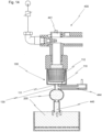
- the Figure 13 shows a schematic representation of a possible filling of the cold casting mold 100 from Figure 2 by means of electrophoresis, in particular electrofiltration.
- the filling means 400 is designed here in the form of an electrophoretic device.
- the mixing compound 200 is conductive, for example comprising a metallic powder
- the cold casting mold 100 is optionally made as an insulator, for example from plastic or also conductive, from conductive polymers.
- the at least one first opening 111 of the cold casting mold 100 is connected in a conductive manner to a cathode 430 of the filling means 400 via the mixing compound 200.
- the plurality of second openings 112 are also connected in a conductive manner to an anode 431 of the filling means 400 via the conductive mixing compound 200.
- a voltage via a voltage source 432, an electric current can be generated which causes particles to be transported from the cathode 430 to the anode 431.
- Tests have shown that approximately 80% of the diluent 205 escapes from the mixing compound 200 during the electrophoretic filling of the cold casting mold 100, which leads to a significantly shortened process time.
- the remaining moisture content remaining in the mixing compound 200 escapes, as described in detail above, via the large number of second openings 112, in particular via porous and/or hygroscopic surfaces formed by them, until the mixing compound 200 hardens and/or solidifies.
- the first opening 111 arranged in the area of the cathode 430 or an adjoining filling channel 130 is provided with a tubular siphon 433, which, in the case of aqueous mixing compounds 200, enables the hydrogen that forms there to escape in order to ensure the homogeneity of the mixing compound 200.
- the Figure 14 shows a schematic sectional view of the cold casting mold 100 from the Figures 1 and 2 , which is pneumatically filled with mixing compound 200 under pressure.
- This process is particularly suitable for homogeneous filling of powdered mixing compounds 200, but also for slip or pasty masses.
- the cold casting mold 100 or its cavity 110 is filled in the manner of a Vacuum cleaner bag, whereby the pressure within the cavity 110 is lower than the ambient pressure.
- This can be achieved either by feeding the mixing compound 200 to the cavity 110 via a pressurized conveying line 440 of the filling means 400, which is designed here as a pressure device.
- the introduction of the mixing compound 200 into the conveying line 440 can be achieved using rotary valves, pressure vessels and/or pressure conveying systems.
- a vacuum can also be generated in the cavity 110 of the cold casting mold 100, whereby a vacuum conveying or suction conveying of the mixing compound 200 is realized.
- a vacuum generator 441 is used to generate a vacuum centrally or decentrally in order to suck in the mixing compound 200 via the at least one first opening 111 and transport it into the cavity 110 of the cold casting mold 100.
- the mixing compound 200 is retained inside the cavity 110 via the plurality of second openings 112 or the wall sections in between.
- the conveying air 442 used to convey the mixing compound 200 passes through the plurality of second openings 112 and is supplied from the environment via a particle filter 443.
- the control of the filling is simplified via a bypass channel 444, which is fluidically connected to the filling channel 130.
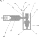
- the Figure 15 finally shows an exemplary embodiment of the invention in which the cold casting mold 100 has a cavity 110 that corresponds to the geometry of a dental molded part 210. Also schematically indicated in the figure is a printing nozzle 310 of a 3D printer 300, by means of which the cold casting mold 100 is additively constructed in one piece from the starting material 150.
- the cold casting mold 100 comprises a first opening 111, which is connected to a filling channel 130 in a fluid-conducting manner via a valve-controlled compensation volume 131.
- the cavity 110 is filled with the mixing compound 200 via the filling channel 130 using a filling means 400, here for example an injection syringe 420.
- Fluids 207 contained in the mixing compound 200 or air inclusions 208 created during filling are discharged from the cavity 110 via a plurality of second openings 112.
- the second openings 112 are designed here as capillaries or pores of the outer walls 121 and are therefore not visible to the naked eye.
- the plurality of second openings 112 creates a porous or hygroscopic surface which conducts fluids 207 or moisture contained in the mixing mass 200 from the cavity into the external environment.
Landscapes
- Health & Medical Sciences (AREA)
- Engineering & Computer Science (AREA)
- Chemical & Material Sciences (AREA)
- Manufacturing & Machinery (AREA)
- Materials Engineering (AREA)
- Veterinary Medicine (AREA)
- Public Health (AREA)
- General Health & Medical Sciences (AREA)
- Oral & Maxillofacial Surgery (AREA)
- Dentistry (AREA)
- Epidemiology (AREA)
- Life Sciences & Earth Sciences (AREA)
- Animal Behavior & Ethology (AREA)
- Mechanical Engineering (AREA)
- Physics & Mathematics (AREA)
- Optics & Photonics (AREA)
- Ceramic Engineering (AREA)
- Civil Engineering (AREA)
- Composite Materials (AREA)
- Structural Engineering (AREA)
- Dental Prosthetics (AREA)
- Dental Preparations (AREA)
- Press-Shaping Or Shaping Using Conveyers (AREA)
Applications Claiming Priority (2)
| Application Number | Priority Date | Filing Date | Title |
|---|---|---|---|
| DE102019128336 | 2019-10-21 | ||
| PCT/EP2020/079500 WO2021078740A2 (de) | 2019-10-21 | 2020-10-20 | Verfahren zur herstellung einer kaltgussform und verwendung einer kaltgussform für die herstellung von formteilen, insbesondere zahnersatz |
Publications (2)
| Publication Number | Publication Date |
|---|---|
| EP4048193A2 EP4048193A2 (de) | 2022-08-31 |
| EP4048193B1 true EP4048193B1 (de) | 2025-01-29 |
Family
ID=73401471
Family Applications (2)
| Application Number | Title | Priority Date | Filing Date |
|---|---|---|---|
| EP20804152.5A Active EP4048193B1 (de) | 2019-10-21 | 2020-10-20 | Verfahren zur herstellung einer kaltgussform und kaltgussform für die herstellung von formteilen, insbesondere zahnersatz |
| EP20804153.3A Active EP4048194B1 (de) | 2019-10-21 | 2020-10-20 | Verfahren zur herstellung von formteilen, insbesondere zahnmedizinischen formteilen |
Family Applications After (1)
| Application Number | Title | Priority Date | Filing Date |
|---|---|---|---|
| EP20804153.3A Active EP4048194B1 (de) | 2019-10-21 | 2020-10-20 | Verfahren zur herstellung von formteilen, insbesondere zahnmedizinischen formteilen |
Country Status (7)
| Country | Link |
|---|---|
| US (2) | US20230271353A1 (pl) |
| EP (2) | EP4048193B1 (pl) |
| JP (2) | JP2022553877A (pl) |
| CN (2) | CN114585324B (pl) |
| DE (1) | DE102020127477A1 (pl) |
| PL (2) | PL4048193T3 (pl) |
| WO (2) | WO2021078740A2 (pl) |
Families Citing this family (4)
| Publication number | Priority date | Publication date | Assignee | Title |
|---|---|---|---|---|
| DE102018008808A1 (de) * | 2018-11-06 | 2020-05-07 | Hans Mathea | Verfahren zum Herstellen eines dreidimensionalen Formgegenstands mittels schichtweisem Materialauftrag |
| EP4146449A4 (en) * | 2020-06-09 | 2024-06-26 | Essentium, Inc. | TOOL FORMED FROM A 3D PRINTED TOOL FRAME |
| CN113415999B (zh) * | 2021-05-25 | 2022-11-18 | 赵凤宇 | 一种供液态打印机使用的微玻金属3d打印微粉 |
| CN118322487B (zh) * | 2024-05-11 | 2025-11-04 | 福建理工大学 | 毛细管冷氮温度匀均恒定装置 |
Family Cites Families (35)
| Publication number | Priority date | Publication date | Assignee | Title |
|---|---|---|---|---|
| GB193481A (en) * | 1921-11-22 | 1923-02-22 | Argyle Dental Company | Improvements in and relating to methods of and apparatus for casting metal articles |
| JPH037057Y2 (pl) * | 1986-10-16 | 1991-02-21 | ||
| JPH0429611Y2 (pl) * | 1988-06-09 | 1992-07-17 | ||
| JP3196171B2 (ja) * | 1993-12-17 | 2001-08-06 | 株式会社ノリタケカンパニーリミテド | 歯科用陶材フレームの製造方法 |
| DE29606662U1 (de) * | 1996-04-12 | 1996-07-25 | Hecker-Cavelius, Harald, 48163 Münster | Gießvorrichtung für dentale Gießverfahren o.dgl. mit Entlüftungseinrichtung |
| JPH1134081A (ja) * | 1997-07-23 | 1999-02-09 | Ebara Corp | 樹脂製素材の成形方法 |
| US6428725B1 (en) | 1998-01-16 | 2002-08-06 | Stefan Wolz | Method for producing completely ceramic structures in the field of dentistry |
| DE19801534C2 (de) | 1998-01-16 | 2001-05-23 | Stefan Wolz | Auftragvorrichtung für Keramikmassen und Innenrohr, vorzugsweise in der Zahntechnik |
| JP3525718B2 (ja) * | 1998-01-30 | 2004-05-10 | 松下電工株式会社 | 注型型及び注型方法 |
| US20050023710A1 (en) * | 1998-07-10 | 2005-02-03 | Dmitri Brodkin | Solid free-form fabrication methods for the production of dental restorations |
| PL374897A1 (pl) | 2002-11-05 | 2005-11-14 | Stefan Wolz | Sposób wytwarzania pełnoceramicznych elementów uzębienia o określonej formie przestrzennej z zastosowaniem elektroforezy |
| US20050040551A1 (en) * | 2003-08-19 | 2005-02-24 | Biegler Robert M. | Hardenable dental article and method of manufacturing the same |
| DE10339603B4 (de) | 2003-08-28 | 2006-08-10 | Stefan Wolz | Verfahren zur Beschichtung dentaler Substrate mittels Elektrophorese |
| DE102005023727B4 (de) | 2005-05-23 | 2007-06-14 | Stefan Wolz | Vorrichtung zum Lagern, Konditionieren und Applizieren von Schlicker in der Dentaltechnik, sowie Verfahren zum Konditionieren von Schlicker |
| DE102005052113A1 (de) | 2005-06-03 | 2006-12-28 | Stefan Wolz | Verfahren zur Herstellung von Zahnteilen aus Dentalmetallpulver |
| DE102006041790B4 (de) * | 2006-09-06 | 2012-04-26 | Ivoclar Vivadent Ag | Küvette |
| WO2008114142A1 (en) | 2007-03-16 | 2008-09-25 | Noritake Dental Supply Co., Limited | Ceramic frameworks and methods of manufacture thereof |
| US8828287B2 (en) | 2009-03-25 | 2014-09-09 | Oratio B.V. | Veneered dental restoration with a controlled shade |
| WO2011020688A1 (de) | 2009-08-17 | 2011-02-24 | Wdt-Wolz-Dental-Technik Gmbh | Vorrichtung zum sauerstofffreien sintern |
| DE102009039102B4 (de) | 2009-08-27 | 2022-01-27 | Wdt-Wolz-Dental-Technik Gmbh | Verfahren zur Herstellung von Zahnteilen aus Dentalmetallpulver |
| DE102011106950A1 (de) | 2011-07-08 | 2013-01-10 | Wdt-Wolz-Dental-Technik Gmbh | Verfahren zur Herstellung eines metallischen Körpers aus mindestens zwei optisch unterschiedlichen Metallen |
| DE202011106734U1 (de) | 2011-10-13 | 2011-11-15 | Wdt-Wolz-Dental-Technik Gmbh | Vorrichtung zum sauerstofffreien Sintern von Metall oder Keramik |
| EP2844412B1 (de) | 2012-05-05 | 2022-11-30 | WDT-Wolz-Dental-Technik GmbH | Sintereinsatz für einen sinterofen zum sauerstofffreien sintern von metall oder keramik |
| US11048829B2 (en) * | 2013-03-15 | 2021-06-29 | Kemeera Llc | 3D printing systems and methods for fabricating injection molds |
| WO2015112885A1 (en) * | 2014-01-23 | 2015-07-30 | United Technologies Corporation | An additive manufactured mold, a method of manufacturing the mold, and a workpiece casted from the mold |
| CN106573294B (zh) * | 2014-08-02 | 2021-01-01 | 沃克斯艾捷特股份有限公司 | 方法和具体地用于冷铸造方法的铸造模具 |
| JP6607557B2 (ja) | 2015-06-06 | 2019-11-20 | 株式会社シントー | 積層造形成形型およびその成形型を用いた射出成形方法 |
| JP6971235B2 (ja) * | 2015-12-17 | 2021-11-24 | スリーエム イノベイティブ プロパティズ カンパニー | ワンピース状歯科修復物用モールド |
| US20180009032A1 (en) | 2016-07-08 | 2018-01-11 | General Electric Company | Metal objects and methods for making metal objects using disposable molds |
| CN106175946A (zh) * | 2016-08-29 | 2016-12-07 | 北京缔佳医疗器械有限公司 | 一种牙齿矫治器的生产方法及装置 |
| US20180098828A1 (en) | 2016-10-07 | 2018-04-12 | 3M Innovative Properties Company | Ceramic dental restorations made by additive manufacturing |
| CN106694872A (zh) | 2016-11-18 | 2017-05-24 | 华中科技大学 | 一种适用于零件与模具的复合增材制造方法 |
| US11648706B2 (en) | 2018-04-26 | 2023-05-16 | San Diego State University Research Foundation | Selective sinter-based fabrication of fully dense complexing shaped parts |
| US11229952B2 (en) * | 2018-08-20 | 2022-01-25 | Honeywell International Inc. | System and method for forming part from rapidly manufactured article |
| DE202019102345U1 (de) * | 2019-04-25 | 2019-05-09 | GreenLife Technology Co., Ltd. | formgebendes Formwerkzeug zur Bildung eines porösen Stärkebehältnisses sowie Stärkebehältnis |
-
2020
- 2020-10-19 DE DE102020127477.7A patent/DE102020127477A1/de active Pending
- 2020-10-20 JP JP2022550044A patent/JP2022553877A/ja active Pending
- 2020-10-20 CN CN202080073678.6A patent/CN114585324B/zh active Active
- 2020-10-20 PL PL20804152.5T patent/PL4048193T3/pl unknown
- 2020-10-20 JP JP2022550045A patent/JP7673936B2/ja active Active
- 2020-10-20 EP EP20804152.5A patent/EP4048193B1/de active Active
- 2020-10-20 WO PCT/EP2020/079500 patent/WO2021078740A2/de not_active Ceased
- 2020-10-20 EP EP20804153.3A patent/EP4048194B1/de active Active
- 2020-10-20 US US17/769,026 patent/US20230271353A1/en active Pending
- 2020-10-20 CN CN202080073672.9A patent/CN114585494B/zh active Active
- 2020-10-20 WO PCT/EP2020/079503 patent/WO2021078742A1/de not_active Ceased
- 2020-10-20 US US17/768,995 patent/US20230271352A1/en active Pending
- 2020-10-20 PL PL20804153.3T patent/PL4048194T3/pl unknown
Also Published As
| Publication number | Publication date |
|---|---|
| JP2022553878A (ja) | 2022-12-26 |
| DE102020127477A1 (de) | 2021-04-22 |
| CN114585494A (zh) | 2022-06-03 |
| PL4048193T3 (pl) | 2025-06-09 |
| EP4048194B1 (de) | 2024-08-07 |
| CN114585324A (zh) | 2022-06-03 |
| WO2021078740A2 (de) | 2021-04-29 |
| JP7673936B2 (ja) | 2025-05-09 |
| EP4048193A2 (de) | 2022-08-31 |
| WO2021078740A3 (de) | 2021-06-17 |
| CN114585324B (zh) | 2024-12-06 |
| WO2021078740A4 (de) | 2021-08-12 |
| CN114585494B (zh) | 2026-07-31 |
| EP4048194A1 (de) | 2022-08-31 |
| JP2022553877A (ja) | 2022-12-26 |
| US20230271352A1 (en) | 2023-08-31 |
| WO2021078742A1 (de) | 2021-04-29 |
| US20230271353A1 (en) | 2023-08-31 |
| PL4048194T3 (pl) | 2025-01-13 |
Similar Documents
| Publication | Publication Date | Title |
|---|---|---|
| EP4048194B1 (de) | Verfahren zur herstellung von formteilen, insbesondere zahnmedizinischen formteilen | |
| DE102004052365B4 (de) | Verfahren zur Herstellung eines Rapid-Prototyping-Modells, eines Grünlings, eines Keramikbauteils und eines metallischen Bauteils | |
| EP1087720B1 (de) | Verfahren zur herstellung medizinischer, zahnmedizinischer, zahntechnischer und technischer teile aus keramik | |
| EP0231773A1 (de) | Verfahren und Ofen zur Herstellung von Zahnersatzteilen | |
| DE102004052364A1 (de) | Verfahren zum Herstellen eines dentalen Modells, eines dentalen Modells mit darauf abgeschiedener Keramikschicht, sowie eines Dentalformteils, dentales Modell, sowie Verwendung eines 3D-Druckers und eines Kits | |
| EP3173202B1 (de) | Spezial-keramikbauteile | |
| DE19930564A1 (de) | Verfahren zur Herstellung medizinischer, zahnmedizinischer, zahntechnischer und technischer Teile aus Keramik | |
| DE10342231B4 (de) | Rohling zur Herstellung eines Zahnersatzteils und Verfahren zur Herstellung desselben | |
| EP1601304A1 (de) | Verfahren zur herstellung eines zahnersatzteils aus metallischen werkstoffen und rohling hierzu | |
| EP3977959B1 (de) | Verfahren zur herstellung eines dentalen formkörpers | |
| EP3173227A1 (de) | Freiform-keramikbauteile | |
| DE102014104596B4 (de) | Aufbau einer Diffusionsbarriere in einem schlickerbasierten additiven Fertigungsprozess zur Herstellung eines keramischen Grünkörpers | |
| DE4217115C2 (de) | Medizinische keramische Paßkörper, beispielsweise medizinische Implantate, Prothesen und Zahnrestaurationen, sowie ein Verfahren zu ihrer Herstellung | |
| DE102014209085B4 (de) | Herstellung eines Formkörpers aus einer Dentallegierung | |
| DE102014119736A1 (de) | Gussform und Verfahren zu deren Herstellung sowie Verfahren zur Herstellung von Gussteilen | |
| DE102008036661A1 (de) | Verfahren zur Herstellung von oxidischer Zahnkeramik | |
| DE102006034551A1 (de) | Keramik-Weißling zur Herstellung eines Keramik-Formteils und Verfahren zur Herstellung eines Keramik-Weißlings sowie eines Keramik-Formteils | |
| DE19703175A1 (de) | Verfahren zur Herstellung von keramischen oder pulvermetallurgischen Bauteilen mit einer schraubenförmigen Außenkontur | |
| EP0842130B1 (de) | Verfahren zur herstellung von keramischen oder pulvermetallurgischen bauteilen mit einer schraubenförmigen aussenkontur und keramisches oder pulvermetallurgisches bauteil mit schraubenförmiger aussenkontur | |
| DE102017202417B3 (de) | Formkörper und Verfahren sowie Vorrichtung zu dessen Herstellung | |
| EP3173392A1 (de) | Verfahren und vorrichtung zur herstellung von keramikteilen | |
| DE19722004A1 (de) | Verfahren zur Herstellung eines Metall- oder Keramikwerkstücks |
Legal Events
| Date | Code | Title | Description |
|---|---|---|---|
| STAA | Information on the status of an ep patent application or granted ep patent |
Free format text: STATUS: UNKNOWN |
|
| STAA | Information on the status of an ep patent application or granted ep patent |
Free format text: STATUS: THE INTERNATIONAL PUBLICATION HAS BEEN MADE |
|
| PUAI | Public reference made under article 153(3) epc to a published international application that has entered the european phase |
Free format text: ORIGINAL CODE: 0009012 |
|
| STAA | Information on the status of an ep patent application or granted ep patent |
Free format text: STATUS: REQUEST FOR EXAMINATION WAS MADE |
|
| 17P | Request for examination filed |
Effective date: 20220516 |
|
| AK | Designated contracting states |
Kind code of ref document: A2 Designated state(s): AL AT BE BG CH CY CZ DE DK EE ES FI FR GB GR HR HU IE IS IT LI LT LU LV MC MK MT NL NO PL PT RO RS SE SI SK SM TR |
|
| DAV | Request for validation of the european patent (deleted) | ||
| DAX | Request for extension of the european patent (deleted) | ||
| STAA | Information on the status of an ep patent application or granted ep patent |
Free format text: STATUS: EXAMINATION IS IN PROGRESS |
|
| 17Q | First examination report despatched |
Effective date: 20230706 |
|
| GRAP | Despatch of communication of intention to grant a patent |
Free format text: ORIGINAL CODE: EPIDOSNIGR1 |
|
| STAA | Information on the status of an ep patent application or granted ep patent |
Free format text: STATUS: GRANT OF PATENT IS INTENDED |
|
| INTG | Intention to grant announced |
Effective date: 20240916 |
|
| GRAS | Grant fee paid |
Free format text: ORIGINAL CODE: EPIDOSNIGR3 |
|
| GRAA | (expected) grant |
Free format text: ORIGINAL CODE: 0009210 |
|
| STAA | Information on the status of an ep patent application or granted ep patent |
Free format text: STATUS: THE PATENT HAS BEEN GRANTED |
|
| AK | Designated contracting states |
Kind code of ref document: B1 Designated state(s): AL AT BE BG CH CY CZ DE DK EE ES FI FR GB GR HR HU IE IS IT LI LT LU LV MC MK MT NL NO PL PT RO RS SE SI SK SM TR |
|
| REG | Reference to a national code |
Ref country code: GB Ref legal event code: FG4D Free format text: NOT ENGLISH |
|
| REG | Reference to a national code |
Ref country code: CH Ref legal event code: EP |
|
| REG | Reference to a national code |
Ref country code: DE Ref legal event code: R096 Ref document number: 502020010340 Country of ref document: DE |
|
| REG | Reference to a national code |
Ref country code: IE Ref legal event code: FG4D Free format text: LANGUAGE OF EP DOCUMENT: GERMAN |
|
| P01 | Opt-out of the competence of the unified patent court (upc) registered |
Free format text: CASE NUMBER: APP_5060/2025 Effective date: 20250130 |
|
| REG | Reference to a national code |
Ref country code: NL Ref legal event code: MP Effective date: 20250129 |
|
| PG25 | Lapsed in a contracting state [announced via postgrant information from national office to epo] |
Ref country code: NL Free format text: LAPSE BECAUSE OF FAILURE TO SUBMIT A TRANSLATION OF THE DESCRIPTION OR TO PAY THE FEE WITHIN THE PRESCRIBED TIME-LIMIT Effective date: 20250129 |
|
| PG25 | Lapsed in a contracting state [announced via postgrant information from national office to epo] |
Ref country code: RS Free format text: LAPSE BECAUSE OF FAILURE TO SUBMIT A TRANSLATION OF THE DESCRIPTION OR TO PAY THE FEE WITHIN THE PRESCRIBED TIME-LIMIT Effective date: 20250429 |
|
| PG25 | Lapsed in a contracting state [announced via postgrant information from national office to epo] |
Ref country code: FI Free format text: LAPSE BECAUSE OF FAILURE TO SUBMIT A TRANSLATION OF THE DESCRIPTION OR TO PAY THE FEE WITHIN THE PRESCRIBED TIME-LIMIT Effective date: 20250129 |
|
| PG25 | Lapsed in a contracting state [announced via postgrant information from national office to epo] |
Ref country code: ES Free format text: LAPSE BECAUSE OF FAILURE TO SUBMIT A TRANSLATION OF THE DESCRIPTION OR TO PAY THE FEE WITHIN THE PRESCRIBED TIME-LIMIT Effective date: 20250129 |
|
| REG | Reference to a national code |
Ref country code: LT Ref legal event code: MG9D |
|
| PG25 | Lapsed in a contracting state [announced via postgrant information from national office to epo] |
Ref country code: NO Free format text: LAPSE BECAUSE OF FAILURE TO SUBMIT A TRANSLATION OF THE DESCRIPTION OR TO PAY THE FEE WITHIN THE PRESCRIBED TIME-LIMIT Effective date: 20250429 Ref country code: IS Free format text: LAPSE BECAUSE OF FAILURE TO SUBMIT A TRANSLATION OF THE DESCRIPTION OR TO PAY THE FEE WITHIN THE PRESCRIBED TIME-LIMIT Effective date: 20250529 |
|
| PG25 | Lapsed in a contracting state [announced via postgrant information from national office to epo] |
Ref country code: HR Free format text: LAPSE BECAUSE OF FAILURE TO SUBMIT A TRANSLATION OF THE DESCRIPTION OR TO PAY THE FEE WITHIN THE PRESCRIBED TIME-LIMIT Effective date: 20250129 |
|
| PG25 | Lapsed in a contracting state [announced via postgrant information from national office to epo] |
Ref country code: LV Free format text: LAPSE BECAUSE OF FAILURE TO SUBMIT A TRANSLATION OF THE DESCRIPTION OR TO PAY THE FEE WITHIN THE PRESCRIBED TIME-LIMIT Effective date: 20250129 Ref country code: PT Free format text: LAPSE BECAUSE OF FAILURE TO SUBMIT A TRANSLATION OF THE DESCRIPTION OR TO PAY THE FEE WITHIN THE PRESCRIBED TIME-LIMIT Effective date: 20250529 |
|
| PG25 | Lapsed in a contracting state [announced via postgrant information from national office to epo] |
Ref country code: BG Free format text: LAPSE BECAUSE OF FAILURE TO SUBMIT A TRANSLATION OF THE DESCRIPTION OR TO PAY THE FEE WITHIN THE PRESCRIBED TIME-LIMIT Effective date: 20250129 Ref country code: GR Free format text: LAPSE BECAUSE OF FAILURE TO SUBMIT A TRANSLATION OF THE DESCRIPTION OR TO PAY THE FEE WITHIN THE PRESCRIBED TIME-LIMIT Effective date: 20250430 |
|
| PG25 | Lapsed in a contracting state [announced via postgrant information from national office to epo] |
Ref country code: SE Free format text: LAPSE BECAUSE OF FAILURE TO SUBMIT A TRANSLATION OF THE DESCRIPTION OR TO PAY THE FEE WITHIN THE PRESCRIBED TIME-LIMIT Effective date: 20250129 |
|
| PG25 | Lapsed in a contracting state [announced via postgrant information from national office to epo] |
Ref country code: SM Free format text: LAPSE BECAUSE OF FAILURE TO SUBMIT A TRANSLATION OF THE DESCRIPTION OR TO PAY THE FEE WITHIN THE PRESCRIBED TIME-LIMIT Effective date: 20250129 |
|
| PG25 | Lapsed in a contracting state [announced via postgrant information from national office to epo] |
Ref country code: DK Free format text: LAPSE BECAUSE OF FAILURE TO SUBMIT A TRANSLATION OF THE DESCRIPTION OR TO PAY THE FEE WITHIN THE PRESCRIBED TIME-LIMIT Effective date: 20250129 |
|
| PG25 | Lapsed in a contracting state [announced via postgrant information from national office to epo] |
Ref country code: EE Free format text: LAPSE BECAUSE OF FAILURE TO SUBMIT A TRANSLATION OF THE DESCRIPTION OR TO PAY THE FEE WITHIN THE PRESCRIBED TIME-LIMIT Effective date: 20250129 |
|
| PG25 | Lapsed in a contracting state [announced via postgrant information from national office to epo] |
Ref country code: RO Free format text: LAPSE BECAUSE OF FAILURE TO SUBMIT A TRANSLATION OF THE DESCRIPTION OR TO PAY THE FEE WITHIN THE PRESCRIBED TIME-LIMIT Effective date: 20250129 |
|
| PG25 | Lapsed in a contracting state [announced via postgrant information from national office to epo] |
Ref country code: SK Free format text: LAPSE BECAUSE OF FAILURE TO SUBMIT A TRANSLATION OF THE DESCRIPTION OR TO PAY THE FEE WITHIN THE PRESCRIBED TIME-LIMIT Effective date: 20250129 |
|
| REG | Reference to a national code |
Ref country code: DE Ref legal event code: R097 Ref document number: 502020010340 Country of ref document: DE |
|
| REG | Reference to a national code |
Ref country code: CH Ref legal event code: U11 Free format text: ST27 STATUS EVENT CODE: U-0-0-U10-U11 (AS PROVIDED BY THE NATIONAL OFFICE) Effective date: 20251101 |
|
| PLBE | No opposition filed within time limit |
Free format text: ORIGINAL CODE: 0009261 |
|
| STAA | Information on the status of an ep patent application or granted ep patent |
Free format text: STATUS: NO OPPOSITION FILED WITHIN TIME LIMIT |
|
| 26N | No opposition filed |
Effective date: 20251030 |
|
| PGFP | Annual fee paid to national office [announced via postgrant information from national office to epo] |
Ref country code: GB Payment date: 20251024 Year of fee payment: 6 |
|
| PGFP | Annual fee paid to national office [announced via postgrant information from national office to epo] |
Ref country code: AT Payment date: 20251021 Year of fee payment: 6 |
|
| PGFP | Annual fee paid to national office [announced via postgrant information from national office to epo] |
Ref country code: IT Payment date: 20251031 Year of fee payment: 6 |
|
| PGFP | Annual fee paid to national office [announced via postgrant information from national office to epo] |
Ref country code: FR Payment date: 20251022 Year of fee payment: 6 |
|
| PGFP | Annual fee paid to national office [announced via postgrant information from national office to epo] |
Ref country code: CH Payment date: 20251101 Year of fee payment: 6 |
|
| PGFP | Annual fee paid to national office [announced via postgrant information from national office to epo] |
Ref country code: CZ Payment date: 20251007 Year of fee payment: 6 |
|
| PGFP | Annual fee paid to national office [announced via postgrant information from national office to epo] |
Ref country code: PL Payment date: 20251007 Year of fee payment: 6 |
|
| PGFP | Annual fee paid to national office [announced via postgrant information from national office to epo] |
Ref country code: DE Payment date: 20251222 Year of fee payment: 6 |
|
| PG25 | Lapsed in a contracting state [announced via postgrant information from national office to epo] |
Ref country code: LU Free format text: LAPSE BECAUSE OF NON-PAYMENT OF DUE FEES Effective date: 20251020 |
|
| REG | Reference to a national code |
Ref country code: BE Ref legal event code: MM Effective date: 20251031 |
|
| PG25 | Lapsed in a contracting state [announced via postgrant information from national office to epo] |
Ref country code: LT Free format text: LAPSE BECAUSE OF FAILURE TO SUBMIT A TRANSLATION OF THE DESCRIPTION OR TO PAY THE FEE WITHIN THE PRESCRIBED TIME-LIMIT Effective date: 20250129 |
|
| PG25 | Lapsed in a contracting state [announced via postgrant information from national office to epo] |
Ref country code: MC Free format text: LAPSE BECAUSE OF FAILURE TO SUBMIT A TRANSLATION OF THE DESCRIPTION OR TO PAY THE FEE WITHIN THE PRESCRIBED TIME-LIMIT Effective date: 20250129 |
|
| PG25 | Lapsed in a contracting state [announced via postgrant information from national office to epo] |
Ref country code: BE Free format text: LAPSE BECAUSE OF NON-PAYMENT OF DUE FEES Effective date: 20251031 |