EP4049954A1 - Procédé de fabrication de rouleau de papier sans noyau - Google Patents
Procédé de fabrication de rouleau de papier sans noyau Download PDFInfo
- Publication number
- EP4049954A1 EP4049954A1 EP20957908.5A EP20957908A EP4049954A1 EP 4049954 A1 EP4049954 A1 EP 4049954A1 EP 20957908 A EP20957908 A EP 20957908A EP 4049954 A1 EP4049954 A1 EP 4049954A1
- Authority
- EP
- European Patent Office
- Prior art keywords
- paper
- shaft
- roll paper
- roll
- adhesive
- Prior art date
- Legal status (The legal status is an assumption and is not a legal conclusion. Google has not performed a legal analysis and makes no representation as to the accuracy of the status listed.)
- Granted
Links
Images


Classifications
-
- B—PERFORMING OPERATIONS; TRANSPORTING
- B65—CONVEYING; PACKING; STORING; HANDLING THIN OR FILAMENTARY MATERIAL
- B65H—HANDLING THIN OR FILAMENTARY MATERIAL, e.g. SHEETS, WEBS, CABLES
- B65H19/00—Changing the web roll
- B65H19/22—Changing the web roll in winding mechanisms or in connection with winding operations
- B65H19/2276—The web roll being driven by a winding mechanism of the coreless type
-
- B—PERFORMING OPERATIONS; TRANSPORTING
- B65—CONVEYING; PACKING; STORING; HANDLING THIN OR FILAMENTARY MATERIAL
- B65H—HANDLING THIN OR FILAMENTARY MATERIAL, e.g. SHEETS, WEBS, CABLES
- B65H18/00—Winding webs
- B65H18/28—Wound package of webs
-
- B—PERFORMING OPERATIONS; TRANSPORTING
- B31—MAKING ARTICLES OF PAPER, CARDBOARD OR MATERIAL WORKED IN A MANNER ANALOGOUS TO PAPER; WORKING PAPER, CARDBOARD OR MATERIAL WORKED IN A MANNER ANALOGOUS TO PAPER
- B31C—MAKING WOUND ARTICLES, e.g. WOUND TUBES, OF PAPER, CARDBOARD OR MATERIAL WORKED IN A MANNER ANALOGOUS TO PAPER
- B31C1/00—Making tubes or pipes by feeding at right angles to the winding mandrel centre line
- B31C1/08—Accessories of machines therefor not otherwise provided for
- B31C1/083—Winding mandrels
-
- B—PERFORMING OPERATIONS; TRANSPORTING
- B31—MAKING ARTICLES OF PAPER, CARDBOARD OR MATERIAL WORKED IN A MANNER ANALOGOUS TO PAPER; WORKING PAPER, CARDBOARD OR MATERIAL WORKED IN A MANNER ANALOGOUS TO PAPER
- B31C—MAKING WOUND ARTICLES, e.g. WOUND TUBES, OF PAPER, CARDBOARD OR MATERIAL WORKED IN A MANNER ANALOGOUS TO PAPER
- B31C11/00—Machinery for winding combined with other machinery
-
- B—PERFORMING OPERATIONS; TRANSPORTING
- B31—MAKING ARTICLES OF PAPER, CARDBOARD OR MATERIAL WORKED IN A MANNER ANALOGOUS TO PAPER; WORKING PAPER, CARDBOARD OR MATERIAL WORKED IN A MANNER ANALOGOUS TO PAPER
- B31C—MAKING WOUND ARTICLES, e.g. WOUND TUBES, OF PAPER, CARDBOARD OR MATERIAL WORKED IN A MANNER ANALOGOUS TO PAPER
- B31C5/00—Making tubes or pipes without using mandrels
-
- B—PERFORMING OPERATIONS; TRANSPORTING
- B31—MAKING ARTICLES OF PAPER, CARDBOARD OR MATERIAL WORKED IN A MANNER ANALOGOUS TO PAPER; WORKING PAPER, CARDBOARD OR MATERIAL WORKED IN A MANNER ANALOGOUS TO PAPER
- B31C—MAKING WOUND ARTICLES, e.g. WOUND TUBES, OF PAPER, CARDBOARD OR MATERIAL WORKED IN A MANNER ANALOGOUS TO PAPER
- B31C99/00—Subject matter not provided for in other groups of this subclass
-
- B—PERFORMING OPERATIONS; TRANSPORTING
- B65—CONVEYING; PACKING; STORING; HANDLING THIN OR FILAMENTARY MATERIAL
- B65H—HANDLING THIN OR FILAMENTARY MATERIAL, e.g. SHEETS, WEBS, CABLES
- B65H18/00—Winding webs
- B65H18/02—Supporting web roll
- B65H18/04—Interior-supporting
-
- B—PERFORMING OPERATIONS; TRANSPORTING
- B65—CONVEYING; PACKING; STORING; HANDLING THIN OR FILAMENTARY MATERIAL
- B65H—HANDLING THIN OR FILAMENTARY MATERIAL, e.g. SHEETS, WEBS, CABLES
- B65H18/00—Winding webs
- B65H18/08—Web-winding mechanisms
- B65H18/14—Mechanisms in which power is applied to web roll, e.g. to effect continuous advancement of web
- B65H18/20—Mechanisms in which power is applied to web roll, e.g. to effect continuous advancement of web the web roll being supported on two parallel rollers at least one of which is driven
-
- B—PERFORMING OPERATIONS; TRANSPORTING
- B65—CONVEYING; PACKING; STORING; HANDLING THIN OR FILAMENTARY MATERIAL
- B65H—HANDLING THIN OR FILAMENTARY MATERIAL, e.g. SHEETS, WEBS, CABLES
- B65H19/00—Changing the web roll
- B65H19/22—Changing the web roll in winding mechanisms or in connection with winding operations
- B65H19/2292—Removing cores or mandrels from web roll after winding
-
- B—PERFORMING OPERATIONS; TRANSPORTING
- B65—CONVEYING; PACKING; STORING; HANDLING THIN OR FILAMENTARY MATERIAL
- B65H—HANDLING THIN OR FILAMENTARY MATERIAL, e.g. SHEETS, WEBS, CABLES
- B65H19/00—Changing the web roll
- B65H19/22—Changing the web roll in winding mechanisms or in connection with winding operations
- B65H19/28—Attaching the leading end of the web to the replacement web-roll core or spindle
- B65H19/286—Attaching the leading end of the web to the replacement web-roll core or spindle by applying adhesive to the web
-
- B—PERFORMING OPERATIONS; TRANSPORTING
- B65—CONVEYING; PACKING; STORING; HANDLING THIN OR FILAMENTARY MATERIAL
- B65H—HANDLING THIN OR FILAMENTARY MATERIAL, e.g. SHEETS, WEBS, CABLES
- B65H19/00—Changing the web roll
- B65H19/22—Changing the web roll in winding mechanisms or in connection with winding operations
- B65H19/30—Lifting, transporting, or removing the web roll; Inserting core
-
- A—HUMAN NECESSITIES
- A47—FURNITURE; DOMESTIC ARTICLES OR APPLIANCES; COFFEE MILLS; SPICE MILLS; SUCTION CLEANERS IN GENERAL
- A47K—SANITARY EQUIPMENT; ACCESSORIES THEREFOR, e.g. TOILET ACCESSORIES
- A47K10/00—Body-drying implements; Toilet paper; Holders therefor
- A47K10/16—Paper towels; Toilet paper; Holders therefor
-
- A—HUMAN NECESSITIES
- A47—FURNITURE; DOMESTIC ARTICLES OR APPLIANCES; COFFEE MILLS; SPICE MILLS; SUCTION CLEANERS IN GENERAL
- A47K—SANITARY EQUIPMENT; ACCESSORIES THEREFOR, e.g. TOILET ACCESSORIES
- A47K10/00—Body-drying implements; Toilet paper; Holders therefor
- A47K10/24—Towel dispensers; Toilet paper dispensers
- A47K10/32—Dispensers for paper towels or toilet paper
- A47K2010/3206—Coreless paper rolls
-
- B—PERFORMING OPERATIONS; TRANSPORTING
- B65—CONVEYING; PACKING; STORING; HANDLING THIN OR FILAMENTARY MATERIAL
- B65H—HANDLING THIN OR FILAMENTARY MATERIAL, e.g. SHEETS, WEBS, CABLES
- B65H2301/00—Handling processes for sheets or webs
- B65H2301/40—Type of handling process
- B65H2301/41—Winding, unwinding
- B65H2301/414—Winding
- B65H2301/41419—Starting winding process
- B65H2301/41429—Starting winding process in coreless applications
-
- B—PERFORMING OPERATIONS; TRANSPORTING
- B65—CONVEYING; PACKING; STORING; HANDLING THIN OR FILAMENTARY MATERIAL
- B65H—HANDLING THIN OR FILAMENTARY MATERIAL, e.g. SHEETS, WEBS, CABLES
- B65H2301/00—Handling processes for sheets or webs
- B65H2301/40—Type of handling process
- B65H2301/41—Winding, unwinding
- B65H2301/417—Handling or changing web rolls
- B65H2301/418—Changing web roll
- B65H2301/4185—Core or mandrel discharge or removal, also organisation of core removal
- B65H2301/41852—Core or mandrel discharge or removal, also organisation of core removal by extracting mandrel from wound roll, e.g. in coreless applications
-
- B—PERFORMING OPERATIONS; TRANSPORTING
- B65—CONVEYING; PACKING; STORING; HANDLING THIN OR FILAMENTARY MATERIAL
- B65H—HANDLING THIN OR FILAMENTARY MATERIAL, e.g. SHEETS, WEBS, CABLES
- B65H2404/00—Parts for transporting or guiding the handled material
- B65H2404/50—Surface of the elements in contact with the forwarded or guided material
- B65H2404/52—Surface of the elements in contact with the forwarded or guided material other geometrical properties
- B65H2404/521—Reliefs
- B65H2404/5213—Geometric details
- B65H2404/52131—Grooves
-
- B—PERFORMING OPERATIONS; TRANSPORTING
- B65—CONVEYING; PACKING; STORING; HANDLING THIN OR FILAMENTARY MATERIAL
- B65H—HANDLING THIN OR FILAMENTARY MATERIAL, e.g. SHEETS, WEBS, CABLES
- B65H2701/00—Handled material; Storage means
- B65H2701/10—Handled articles or webs
- B65H2701/18—Form of handled article or web
- B65H2701/184—Wound packages
- B65H2701/1842—Wound packages of webs
- B65H2701/18422—Coreless
-
- B—PERFORMING OPERATIONS; TRANSPORTING
- B65—CONVEYING; PACKING; STORING; HANDLING THIN OR FILAMENTARY MATERIAL
- B65H—HANDLING THIN OR FILAMENTARY MATERIAL, e.g. SHEETS, WEBS, CABLES
- B65H2701/00—Handled material; Storage means
- B65H2701/10—Handled articles or webs
- B65H2701/19—Specific article or web
- B65H2701/1924—Napkins or tissues, e.g. dressings, toweling, serviettes, kitchen paper and compresses
Definitions
- the present disclosure relates to a method for producing coreless roll paper.
- Roll paper such as typical toilet paper, includes a core made of tubular cardboard, and a tissue material (paper) is wound around the core to form a roll shape. Hence, after the roll paper is used up, the core needs to be discarded. To eliminate the need of discarding the core, various coreless roll paper has been produced.
- a winding-start end of a tissue material is folded back, moisture is added to the folded back portion, and the tissue material is wound on a winding shaft (shaft) (see Patent Literature 1).
- a hollow, cylindrical inner solidified layer can be formed on the winding shaft side, that is, on the center side of the roll paper.
- This inner solidified layer serves as a core and can be used without being discarded by separating the adhered layers of the tissue material.
- a winding shaft having gear-like grooves in the outer circumferential side surface is used instead of a typical winding shaft with no texture on the outer circumferential surface.
- a tissue material is wound on this grooved winding shaft, the tissue material is wound so as to be stretched between the ridges of the grooves, such that the portions laminated at the positions facing the channels of the grooves are not in contact with the winding shaft.
- a plurality of layers of tissue material near the winding shaft side is wound such that the portions laminated at the positions facing the channels of the grooves are bent toward the axis center.
- the tissue material is loosely wound, compared with a case where a typical winding shaft is used.
- the paper in the inner solidified layer is relatively loosely wound and solidified, in which only the portions laminated on the ridges are adhered, and the other portions are not adhered together. Accordingly, while the inner solidified layer maintains a certain strength that is enough to serve as a core, the layers of the tissue material can be easily separated.
- the present disclosure has been made to solve the problem with the related-art technique described above, and an object thereof is to provide a method for producing coreless roll paper in which it is possible to prevent deformation of roll paper when a winding shaft is extracted, more specifically, to prevent a winding-start end from being pulled out in the case where a tissue material is loosely wound, to enable stable production of coreless roll paper.
- a method for producing coreless roll paper includes: a transport step in which transport means draws paper from a material roll and transports the paper; an application step in which adhesive supply means applies an adhesive to a winding-start end of the paper that is being transported; a winding step in which the paper to which the adhesive has been applied is wound on a shaft and is formed in a roll shape; and an extracting step in which the shaft is extracted from roll paper, which is the paper formed in a roll shape, to form a center hole at the center of the roll paper.
- the shaft includes a body part having gear-like grooves in an outer circumferential side surface thereof, and a cover member is put on and fixed to the body part. In the winding step, the paper is wound on the cover member.
- the shaft is extracted with the cover member left in the roll paper, and then the cover member is removed from the roll paper.
- a method for producing coreless roll paper includes: a transport step in which transport means draws paper from a material roll and transports the paper; a winding step in which the transported paper is wound on a shaft and is formed in a roll shape; an extracting step in which the shaft is extracted from roll paper, which is the paper formed in a roll shape, to form a center hole at the center of the roll paper; and an application step in which adhesive supply means is inserted into the center hole to apply an adhesive to an inner wall portion of the center hole.
- the shaft includes a body part having gear-like grooves in an outer circumferential side surface thereof, and a cover member is put on and fixed to the body part.
- the winding step the paper is wound on the cover member.
- the extracting step the shaft is extracted with the cover member left in the roll paper, and then the cover member is removed from the roll paper.
- the cover member is a flexible, non-adhesive film or sheet.
- the cover member is tubular.
- the method for producing coreless roll paper includes: a transport step in which transport means draws paper from a material roll and transports the paper; an application step in which adhesive supply means applies an adhesive to a winding-start end of the paper that is being transported; a winding step in which the paper to which the adhesive has been applied is wound on a shaft and is formed in a roll shape; and an extracting step in which the shaft is extracted from roll paper, which is the paper formed in a roll shape, to form a center hole at the center of the roll paper.
- the shaft includes a body part having gear-like grooves in an outer circumferential side surface thereof, and a cover member is put on and fixed to the body part. In the winding step, the paper is wound on the cover member.
- a shaft is extracted with a cover member left in roll paper, and then the cover member is removed from the roll paper.
- the cover member is removed from the roll paper.
- the method for producing coreless roll paper includes: a transport step in which transport means draws paper from a material roll and transports the paper; a winding step in which the transported paper is wound on a shaft and is formed in a roll shape; an extracting step in which the shaft is extracted from the roll paper, which is paper formed in a roll shape, to form a center hole at the center of the roll paper; and an application step in which adhesive supply means is inserted into the center hole to apply an adhesive to an inner wall portion of the center hole.
- the shaft includes a body part having gear-like grooves in an outer circumferential side surface thereof, and a cover member is put on and fixed to the body part. In the winding step, paper is wound on the cover member.
- the shaft is extracted with the cover member left in the roll paper. Then, the cover member is removed from the roll paper.
- the cover member is protected from the roll paper.
- the cover member is made of a flexible, non-adhesive film or a sheet. Hence, it is possible to easily put the cover member on the outer circumferential side surface of the shaft. Furthermore, because it is non-adhesive, the friction caused when the shaft is extracted from the roll paper can be reduced. Moreover, when the cover member is removed from the roll paper, the cover member can be easily removed. Accordingly, compared with a case where the cover member is not a flexible, non-adhesive film or sheet, it is possible to more reliably prevent the winding-start end of the paper from being pulled out.
- the cover member is tubular. Hence, it is possible to easily fix the cover member to the outer circumferential side surface of the shaft.
- Fig. 1 is an explanatory diagram showing a schematic structure of a production apparatus 1 for performing a method for producing coreless roll paper according to a first embodiment of the present disclosure, and shows the arrangement configuration of the respective components of the apparatus when the production apparatus 1 is viewed from a side.
- Fig. 2 is an enlarged view showing a shaft 20, serving as a winding shaft in the production apparatus 1, and the vicinity thereof, as viewed from a side.
- a material roll 10 is disposed at a predetermined position, and the production apparatus 1 includes feed rollers 2 and 3, serving as transport means, arranged so as to be in contact with the outer circumference of the material roll 10.
- the feed rollers 2 and 3 draw paper 11 from the material roll 10 and transport the paper toward the shaft 20 (in the transport direction shown by arrow X in Fig. 1 ).
- the paper 11 drawn from the material roll 10 is transported also by a guide and rollers (not shown), besides the feed rollers 2 and 3.
- the production apparatus 1 also includes an adhesive supplier 7 serving as adhesive supply means, and a cutter 8, at a position above the transported paper 11 and between the material roll 10 and the shaft 20.
- the adhesive supplier 7 and the cutter 8 are disposed at a position immediately before the position where the paper 11 transported by the feed rollers 2 and 3 is wound on the shaft 20 (i.e., near the shaft 20).
- the production apparatus 1 also includes winding auxiliary rollers 4 and 5 and a pressure roller 6 in the vicinity of the shaft 20.
- the winding auxiliary rollers 4 and 5 and the pressure roller 6 are arranged so as to allow the transported paper 11 to be wound on the shaft 20.
- the pressure roller 6 is arranged above the shaft 20 and presses, from above, the paper 11 wound on the shaft 20. Hence, the paper 11 is wound under a predetermined tension, while being pressed by the pressure roller 6.
- the pressure roller 6 is supported by support means 9 or the like so as to be movable in the top-bottom direction. Thus, the pressing force thereof is adjusted according to the outside diameter of a roll paper 12, which is the paper 11 wound on the shaft 20 and is formed in a roll shape ( Fig. 2 shows the position relationship among the winding auxiliary rollers 4 and 5, the pressure roller 6, and the roll paper 12).
- the adhesive supplier 7 is disposed above the transported paper 11 (see Fig. 1 ).
- the adhesive supplier 7 applies an adhesive 40 to the surface of the transported paper 11, by jetting or dropping, as droplets, the adhesive 40 from above.
- the adhesive 40 hardens and solidifies the laminated paper 11 when dried.
- the amount of the adhesive 40 to be applied by the adhesive supplier 7 and the area thereof are controlled by control means or the like (not shown). More than one adhesive supplier 7 may be arranged in a straight line between the ends of the paper 11 in the width direction.
- Fig. 1 shows, for the purpose of explaining the adhesive supplier 7, a state in which the adhesive 40 is being applied, in actuality, the adhesive 40 is applied only to the winding-start end (not shown) of the paper 11.
- the cutter 8 is disposed above the paper 11 (see Fig. 1 ).
- the cutter 8 cuts the paper 11 that is drawn toward the shaft 20. More specifically, when the outside diameter of the roll paper 12 has reached a desired value, the cutter 8 is driven to cut the paper 11.
- the driving of the cutter 8 is controlled by control means or the like (not shown).
- a configuration in which the material roll 10 is disposed at a predetermined position, and the paper 11 is fed from the material roll 10 and is wound on the shaft 20 is shown in this embodiment, a configuration is also possible in which a paper making machine including a wire part, a press part, a dryer part, and the like is provided instead of the material roll 10, the feed rollers 2 and 3, and the like, and the paper 11 produced by this paper making machine is transported to the shaft 20 and the like by the transport means.
- Fig. 3 is a perspective view showing an end of the shaft 20 in the production apparatus 1.
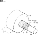
- Fig. 4 is an enlarged view showing the end of the shaft 20.
- the illustration of the winding auxiliary rollers 4 and 5, the pressure roller 6, and the like, shown in Fig. 1 is omitted.
- the shaft 20 is a cylindrical shaft member, and the paper 11 is wound on the outer circumferential side surface of a body part 22 at the center.
- the outside diameter of ends 21 of the shaft 20 is smaller than the outside diameter of the body part 22 (see Fig. 3 ), and the ends 21 are rotatably and removably engaged with engaging portions (not shown) of the production apparatus 1.
- the shaft 20 has grooves 23 formed by cutting straight grooves, extending from one end to the other end of the body part 22, in the outer circumferential side surface of the body part 22. More specifically, a plurality of grooves 23 is successively formed in the circumference of the body part 22. Due to the successive grooves 23, the outer circumferential side surface of the body part 22 has a gear-like structure. In other words, the outer circumferential side surface of the body part 22 has a plurality of ridges 23a and channels 23b arranged alternately in the circumference.
- a sleeve 30, serving as a cover member, is fixed to the shaft 20 so as to cover the grooves 23 in the circumference of the body part 22 (see Fig. 2 ).
- the sleeve 30 is formed of a flexible, non-adhesive film or sheet and is formed in a cylindrical shape.
- the sleeve 30 is fixed in a state in which the shaft 20 passes therethrough and the sleeve 30 is put on the body part 22.
- the sleeve 30 is formed such that the inside diameter thereof is slightly larger than the outside diameter of the body part 22 and thus can be fixed simply by putting it on the body part 22.
- the sleeve 30 is put on the shaft 20 so as to be stretched from a ridge 23a to an adjoining ridge 23a of the grooves 23. Hence, portions of the sleeve 30 opposed to the channels 23b are fixed so as to be slightly bent toward the axis center of the shaft 20 (see Fig. 2 ).
- sleeve 30 Various films or sheets may be used for the sleeve 30.
- a film or a sheet that is made of a synthetic resin such as polyethylene, polypropylene, polyvinyl chloride, or polystyrene, may be used, and the thickness thereof is, for example, from 10 ⁇ m to 1 mm.
- the sleeve 30 be made of a film or a sheet that is made of polyethylene or polypropylene, from the standpoint that it has flexibility, non-adhesiveness, and the property in which it is not easily adhered by a typical adhesive.
- the cover member is the cylindrical sleeve 30 that can be fixed to the body part 22 simply by putting it thereon
- a configuration is also possible in which, for example, the cover member is formed of a rectangular film or sheet, and the film or sheet is wrapped around the body part 22 and is fixed with fastening means (not shown), such as adhesive tape or the like.
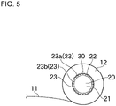
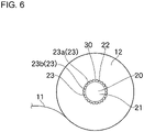
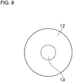
- Figs. 5 , 6 , 7 , and 8 are explanatory diagrams showing transitions of the roll paper 12 produced with the production apparatus 1.
- Fig. 5 shows a state in which the paper 11 is wound to form the roll paper 12
- Fig. 6 shows a state in which the outside diameter of the roll paper 12 has reached a desired value.
- Fig. 7 shows the roll paper 12 after the shaft 20 has been extracted
- Fig. 8 shows the roll paper 12 after the sleeve 30 has been removed from a center hole 13.
- the feed rollers 2 and 3, as shown in Fig. 1 are rotationally driven to rotate the material roll 10, which is in contact with the feed rollers 2 and 3 at the outer circumference thereof.
- the paper 11 is drawn from the material roll 10 and is transported at a predetermined speed.
- the paper 11 drawn from the material roll 10 is transported toward the shaft 20 (in the transport direction, shown by arrow X in Fig. 1 ) at the above-described predetermined speed by a guide and rollers.
- the adhesive supplier 7 applies the adhesive 40 to the winding-start end of the transported paper 11.
- the winding-start end is a portion corresponding to a plurality of layers of the paper 11 to be initially wound on the shaft 20 and is a portion having a length corresponding to, for example, five to twenty turns around the shaft 20 after the end of the paper 11 starts to be wound on the shaft 20.
- the application of the adhesive 40 is started when the end of the paper 11 is transported below the adhesive supplier 7, and the application of the adhesive 40 is stopped when the paper 11 is wound five to twenty turns around the shaft 20.
- the paper 11 reaching the shaft 20 is nipped between the shaft 20 and the winding auxiliary roller 4 and then between the shaft 20 and the winding auxiliary roller 5 and, consequently, is wound on the circumference of the shaft 20.
- the paper 11 passes on the upper-end side of the winding auxiliary rollers 4 and 5 and is wound on the shaft 20 such that the side to which the adhesive 40 has been applied is located on the inner side of the roll.
- the sleeve 30 has been fixed so as to be put on the circumference of the shaft 20, more specifically, the grooves 23 in the body part 22 (see Figs. 5 and 6 ).
- the paper 11 is not directly wound on the shaft 20, but is wound on the shaft 20 with the sleeve 30 therebetween (see Fig. 5 ).
- the paper 11 wound on the shaft 20 and formed in a roll shape is laminated on the sleeve 30 while being pressed by the pressure roller 6.
- the paper 11 is wound without creases and in the form of a perfect circle around the shaft 20, serving as the axis.
- the shaft 20 is removed from the engaging portions of the production apparatus 1, and the roll paper 12 is transferred to a support base (not shown). Then, the shaft 20 is extracted from the roll paper 12 fixed to the support base.
- the center hole 13 which remains after the shaft 20 is extracted, is formed in the center of the roll paper 12, and the sleeve 30 is left in the inner wall portion of the center hole 13 (see Fig. 7 ).
- the center hole 13 is formed as a through-hole extending along the axis of the roll paper 12, and a texture pattern corresponding to the grooves 23 is formed on the inner wall portion (see Figs. 7 and 8 ).
- the sleeve 30 is removed from the inner wall portion of the center hole 13 (see Fig. 8 ).
- the sleeve 30 may be perforated in advance, so that the sleeve 30 can be torn in two by pulling the longitudinal ends of the sleeve 30 in opposite directions. With this configuration, by pulling the ends of the sleeve 30 from the ends of the center hole 13, the sleeve 30 is torn at the perforated line and can be easily removed.
- the adhesive supplier 7 preliminarily applies the adhesive 40 to the ends and the vicinity thereof, and the next shaft 20 is supplied so as to be lightly pressed against this portion. By doing so, it is possible to cut the paper 11 in a state in which the portion serving as the end of the paper 11 is temporarily adhered to the sleeve 30 of the next shaft 20.
- an air jetting device (not shown) may be provided below the cutter 8 to jet air from below to prevent the temporarily adhered paper from peeling off.
- the next shaft 20 to which the end of the paper 11 is temporarily adhered is moved to the position above the winding auxiliary rollers 4 and 5 in accordance with the restart of the transportation of the paper 11. Thereafter, the paper 11 is wound as in the normal winding step.
- the next shaft 20 can be successively supplied to the position above the winding auxiliary rollers 4 and 5 in accordance with the transfer of the roll paper 12 to the support base. This way, it is possible to successively wind the paper 11 on the shaft 20.
- the method for producing coreless roll paper according to this embodiment is configured as above. With this production method, when the shaft 20 is extracted from the roll paper 12, it is possible to extract the shaft 20 from the roll paper 12 while reliably protecting the center hole 13 in the roll paper 12 with the sleeve 30. Accordingly, even though the paper 11 is loosely wound on the shaft 20, it is possible to prevent the winding-start end of the paper 11 from being pulled out when the shaft 20 is extracted, and thus, it is possible to stably produce the coreless roll paper 12.
- Fig. 9 is an explanatory diagram showing a schematic structure of a production apparatus 50 for performing a method for producing coreless roll paper according to the second embodiment of the present disclosure.
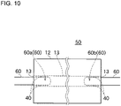
- Fig. 10 is an explanatory diagram showing adhesive suppliers 60 of the production apparatus 50.
- the configurations that are the same as those of the production apparatus 1 will be denoted by the same reference signs, and detailed descriptions thereof will be omitted.
- the configurations different from those in the production apparatus 1 will be mainly described.
- the material roll 10 is disposed at a predetermined position, and the production apparatus 50 includes the feed rollers 2 and 3 arranged so as to be in contact with the outer circumference of the material roll 10, the winding auxiliary rollers 4 and 5 and the pressure roller 6 arranged near the shaft 20, and the cutter 8 arranged near the shaft 20.
- This configuration is the same as that of the production apparatus 1.
- the production apparatus 50 includes a pair of adhesive suppliers 60 opposed to each other, instead of the adhesive supplier 7 of the production apparatus 1.
- the adhesive suppliers 60 are a pair of tubular members with sealed ends and are inserted into the center hole 13 remaining after the shaft 20 is extracted from the roll paper 12 and then the sleeve 30 is removed.
- the movement of insertion ends 60a and 60b of the adhesive suppliers 60 is controlled by control means and the like (not shown), and the insertion ends 60a and 60b are inserted from the ends of the center hole 13 (see Fig. 10 ).
- the insertion ends 60a and 60b have a plurality of jetting holes (not shown) in the circumferences thereof, through which the adhesive 40 is jetted by delivery means, such as a pump or the like (not shown).
- the amount and area of the adhesive 40 jetted from the jetting holes in the insertion ends 60a and 60b are controlled by the delivery means.
- the insertion ends 60a and 60b of the adhesive suppliers 60 are inserted from the ends of the center hole 13. Then, the insertion ends 60a and 60b inserted into the center hole 13 jets the adhesive 40 onto the inner wall portion of the center hole 13 through the jetting holes (see Fig. 10 ). With this configuration, it is possible to apply an appropriate amount of the adhesive 40 only to the minimum area of the inner wall portion of the center hole 13 that needs to be adhered and solidified.
- the method for producing coreless roll paper according to this embodiment is configured as above. With this production method, even though the roll paper 12 is wound without the adhesive 40, it is possible to extract the shaft 20 from the roll paper 12 without causing deformation by protecting the center hole 13 with the sleeve 30. Moreover, because it is possible to directly jet the adhesive 40 to the inner wall portion of the center hole 13 remaining after the shaft 20 is extracted and the sleeve 30 is removed, only the minimum area necessary for preventing deformation of the roll paper 12 can be adhered and solidified. Accordingly, because the portion solidified with the adhesive 40 is small, the coreless roll paper 12 can be easily used up to the end.
Landscapes
- Sanitary Thin Papers (AREA)
- Replacement Of Web Rolls (AREA)
Priority Applications (1)
| Application Number | Priority Date | Filing Date | Title |
|---|---|---|---|
| HUE20957908A HUE065546T2 (hu) | 2020-12-28 | 2020-12-28 | Eljárás mag nélküli papírtekercs elõállítására |
Applications Claiming Priority (1)
| Application Number | Priority Date | Filing Date | Title |
|---|---|---|---|
| PCT/JP2020/049087 WO2022144951A1 (fr) | 2020-12-28 | 2020-12-28 | Procédé de fabrication de rouleau de papier sans noyau |
Publications (3)
| Publication Number | Publication Date |
|---|---|
| EP4049954A1 true EP4049954A1 (fr) | 2022-08-31 |
| EP4049954A4 EP4049954A4 (fr) | 2022-11-30 |
| EP4049954B1 EP4049954B1 (fr) | 2023-11-01 |
Family
ID=76218184
Family Applications (1)
| Application Number | Title | Priority Date | Filing Date |
|---|---|---|---|
| EP20957908.5A Active EP4049954B1 (fr) | 2020-12-28 | 2020-12-28 | Procédé de fabrication de rouleau de papier sans noyau |
Country Status (10)
| Country | Link |
|---|---|
| US (1) | US12202689B2 (fr) |
| EP (1) | EP4049954B1 (fr) |
| JP (1) | JP6883909B1 (fr) |
| KR (1) | KR102648620B1 (fr) |
| CN (1) | CN114980785B (fr) |
| DK (1) | DK4049954T3 (fr) |
| ES (1) | ES2969759T3 (fr) |
| FI (1) | FI4049954T3 (fr) |
| HU (1) | HUE065546T2 (fr) |
| WO (1) | WO2022144951A1 (fr) |
Families Citing this family (1)
| Publication number | Priority date | Publication date | Assignee | Title |
|---|---|---|---|---|
| IT202400004033A1 (it) * | 2024-02-26 | 2025-08-26 | Gambini Spa | Goffratore comprendente un erogatore per irrigidire un velo di carta, linea di converting e processo. |
Family Cites Families (23)
| Publication number | Priority date | Publication date | Assignee | Title |
|---|---|---|---|---|
| JPS58200719A (ja) * | 1982-05-19 | 1983-11-22 | 小林 昌志 | トイレツトペ−パロ−ル及びその製造法 |
| US4763785A (en) * | 1987-10-09 | 1988-08-16 | Basf Aktiengesellschaft | Center-pull fiber package and method for producing the package |
| WO1993021094A1 (fr) * | 1992-04-15 | 1993-10-28 | Yugen Kaisha Kaji Seisakusho | Procede permettant de produire un rouleau de papier hygienique depourvu de noyau et rouleau de papier hygienique depourvu de noyau ainsi produit |
| JP3350151B2 (ja) | 1993-06-23 | 2002-11-25 | 徳七 山崎 | 芯無し紙製シートロール及びその製造方法 |
| EP0589481B1 (fr) | 1992-09-25 | 1999-06-09 | Tokushichi Yamazaki | Méthode pour former un rouleau de matériau en bande sans noyau |
| JP3372279B2 (ja) * | 1992-11-25 | 2003-01-27 | 徳七 山崎 | 芯なしトイレットペーパのログロールの製造方法、及び芯なしトイレットペーパのログロールの巻軸 |
| JPH0815959B2 (ja) * | 1992-11-26 | 1996-02-21 | 有限会社加地製作所 | 芯なしトイレットペーパーロールの製造装置 |
| JPH0781808A (ja) | 1993-09-16 | 1995-03-28 | Ishizu Seisakusho:Kk | トイレット用ロールペーパーの製造方法 |
| US5620148A (en) * | 1995-03-10 | 1997-04-15 | Kimberly-Clark Corporation | Methods of making indented coreless rolls |
| JPH10212070A (ja) * | 1997-01-30 | 1998-08-11 | Toray Ind Inc | 強化繊維パッケージおよびその収納物 |
| US20030132330A1 (en) | 2000-02-15 | 2003-07-17 | Ryuzou Kubota | Toilet paper roll and method of manufacturing the paper roll |
| JP2002037489A (ja) * | 2000-07-18 | 2002-02-06 | Phoenix Kagaku Kenkyusho:Kk | 包装用芯なしフィルムロールの製造方法とその装置及びそのフィルムロール用いた立体包装機 |
| JP4103960B2 (ja) | 2004-11-29 | 2008-06-18 | 株式会社清水製作所 | 芯なしトイレットペーパと、その製造方法および製造装置 |
| EP2252534B1 (fr) * | 2008-02-04 | 2012-04-25 | Georgia-Pacific France | Rouleau de papier a trou central avec element de renfort et procede de fabrication dudit rouleau |
| JP5653687B2 (ja) * | 2010-08-31 | 2015-01-14 | 大王製紙株式会社 | 芯無しトイレットペーパーロールの製造方法及びこれによる芯無しトイレットペーパーロール |
| JP5922382B2 (ja) | 2011-11-29 | 2016-05-24 | 大王製紙株式会社 | 管芯無しトイレットロールの製造方法及び管芯無しトイレットロール |
| US9284147B2 (en) | 2012-09-21 | 2016-03-15 | Paper Converting Machine Company | Method and apparatus for producing coreless rolls of paper |
| JP5592533B1 (ja) | 2013-05-22 | 2014-09-17 | 西日本衛材株式会社 | トイレットペーパの製造方法及びトイレットペーパの製造装置 |
| JP6229897B2 (ja) | 2015-01-21 | 2017-11-15 | コアレックス信栄株式会社 | トイレットペーパー製造方法 |
| JP6517254B2 (ja) | 2017-02-27 | 2019-05-22 | コアレックス信栄株式会社 | 芯なしロールペーパー製造方法 |
| JP6344701B1 (ja) | 2017-03-24 | 2018-06-20 | コアレックス信栄株式会社 | 芯なしロールペーパー製造方法 |
| ES2945436T3 (es) * | 2018-03-19 | 2023-07-03 | Corelex Shin Ei Co Ltd | Procedimiento de fabricación de rollos de papel sin núcleo |
| EP3802386B1 (fr) | 2018-05-24 | 2025-07-30 | Windmöller & Hölscher KG | Douille, équipement d'enroulement et procédé destiné à enrouler plusieurs fois les unes sur les autres des bandes en enroulements de matériau |
-
2020
- 2020-12-28 FI FIEP20957908.5T patent/FI4049954T3/fi active
- 2020-12-28 EP EP20957908.5A patent/EP4049954B1/fr active Active
- 2020-12-28 CN CN202080093198.6A patent/CN114980785B/zh active Active
- 2020-12-28 ES ES20957908T patent/ES2969759T3/es active Active
- 2020-12-28 DK DK20957908.5T patent/DK4049954T3/da active
- 2020-12-28 KR KR1020227020228A patent/KR102648620B1/ko active Active
- 2020-12-28 HU HUE20957908A patent/HUE065546T2/hu unknown
- 2020-12-28 WO PCT/JP2020/049087 patent/WO2022144951A1/fr not_active Ceased
- 2020-12-28 US US17/773,150 patent/US12202689B2/en active Active
- 2020-12-28 JP JP2021514146A patent/JP6883909B1/ja active Active
Also Published As
| Publication number | Publication date |
|---|---|
| KR102648620B1 (ko) | 2024-03-15 |
| US12202689B2 (en) | 2025-01-21 |
| DK4049954T3 (da) | 2023-12-04 |
| US20230159292A1 (en) | 2023-05-25 |
| CN114980785B (zh) | 2023-06-20 |
| JP6883909B1 (ja) | 2021-06-09 |
| EP4049954A4 (fr) | 2022-11-30 |
| JPWO2022144951A1 (fr) | 2022-07-07 |
| EP4049954B1 (fr) | 2023-11-01 |
| WO2022144951A1 (fr) | 2022-07-07 |
| KR20220100033A (ko) | 2022-07-14 |
| FI4049954T3 (fi) | 2024-01-24 |
| CN114980785A (zh) | 2022-08-30 |
| ES2969759T3 (es) | 2024-05-22 |
| HUE065546T2 (hu) | 2024-06-28 |
Similar Documents
| Publication | Publication Date | Title |
|---|---|---|
| US5421536A (en) | Surface winder with recycled mandrels and method | |
| JP4169283B2 (ja) | ウエブ材料のログを形成するためのマルチ処理装置とログ製造方法 | |
| US8220736B2 (en) | Web separator with reverse rotation mechanism for tissue paper winding machine | |
| CN100500534C (zh) | 用于加工带材卷的方法及实施所述方法和重绕机 | |
| KR101279202B1 (ko) | 웨브재의 심이 없는 롤, 그 제조를 위한 머신 및 방법 | |
| US20030080234A1 (en) | Mandrelless center/surface rewinder and winder | |
| EP1888441A2 (fr) | Machine et procede permettant la production de rouleaux de materiau en bande conjointement a un support central d'enroulement et rouleau resultant | |
| EP4049954B1 (fr) | Procédé de fabrication de rouleau de papier sans noyau | |
| US10889458B2 (en) | Method for manufacturing coreless paper roll | |
| US6298634B1 (en) | Process and device for producing a wound roll that is wrapped on its circumference, and the wound roll | |
| CN103213867A (zh) | 宽幅卷材分切装置及分切方法 | |
| JPH11114881A (ja) | スリッタ装置 | |
| JP2008037511A (ja) | ウエブ巻取機 | |
| HK40071696B (en) | Coreless paper roll manufacturing method | |
| KR102390178B1 (ko) | 청소용 점착테이프롤 및 청소용 점착테이프롤 제조 장치 | |
| JP2002128180A (ja) | シートロール包装物及びシートロールの包装方法 | |
| JP4546984B2 (ja) | ウェブ材料の巻取り装置 | |
| HK40071696A (en) | Coreless paper roll manufacturing method | |
| JP2002003031A (ja) | 長尺材の取卸し方法 | |
| JPH1171047A (ja) | スリット製品分離巻取装置 | |
| JP2595140B2 (ja) | 無芯小ロール巻き上げ装置 | |
| JPH05170362A (ja) | ウエブ巻取り装置 | |
| JP2007308237A (ja) | 連続紙の貼り合わせ加工装置 | |
| JP2001058745A (ja) | 無芯ロールペーパー用のウエブ巻回体連続製造方法及びその製造機 | |
| CN103204404A (zh) | 宽幅卷材分切装置及分切方法 |
Legal Events
| Date | Code | Title | Description |
|---|---|---|---|
| STAA | Information on the status of an ep patent application or granted ep patent |
Free format text: STATUS: UNKNOWN |
|
| STAA | Information on the status of an ep patent application or granted ep patent |
Free format text: STATUS: THE INTERNATIONAL PUBLICATION HAS BEEN MADE |
|
| PUAI | Public reference made under article 153(3) epc to a published international application that has entered the european phase |
Free format text: ORIGINAL CODE: 0009012 |
|
| STAA | Information on the status of an ep patent application or granted ep patent |
Free format text: STATUS: REQUEST FOR EXAMINATION WAS MADE |
|
| 17P | Request for examination filed |
Effective date: 20220527 |
|
| AK | Designated contracting states |
Kind code of ref document: A1 Designated state(s): AL AT BE BG CH CY CZ DE DK EE ES FI FR GB GR HR HU IE IS IT LI LT LU LV MC MK MT NL NO PL PT RO RS SE SI SK SM TR |
|
| A4 | Supplementary search report drawn up and despatched |
Effective date: 20221028 |
|
| RIC1 | Information provided on ipc code assigned before grant |
Ipc: B65H 19/28 20060101ALI20221024BHEP Ipc: B65H 75/18 20060101ALI20221024BHEP Ipc: B65H 19/30 20060101ALI20221024BHEP Ipc: B65H 19/22 20060101ALI20221024BHEP Ipc: B65H 18/20 20060101ALI20221024BHEP Ipc: A47K 10/16 20060101ALI20221024BHEP Ipc: B65H 18/04 20060101AFI20221024BHEP |
|
| REG | Reference to a national code |
Ref legal event code: R079 Ref country code: DE Ref document number: 602020020518 Country of ref document: DE Free format text: PREVIOUS MAIN CLASS: B65H0018040000 Ipc: B65H0019220000 |
|
| RIC1 | Information provided on ipc code assigned before grant |
Ipc: B31C 11/00 20060101ALI20230228BHEP Ipc: B31C 1/08 20060101ALI20230228BHEP Ipc: A47K 10/32 20060101ALI20230228BHEP Ipc: A47K 10/16 20060101ALI20230228BHEP Ipc: B65H 75/18 20060101ALI20230228BHEP Ipc: B65H 19/30 20060101ALI20230228BHEP Ipc: B65H 18/04 20060101ALI20230228BHEP Ipc: B65H 18/20 20060101ALI20230228BHEP Ipc: B65H 19/28 20060101ALI20230228BHEP Ipc: B65H 19/22 20060101AFI20230228BHEP |
|
| GRAP | Despatch of communication of intention to grant a patent |
Free format text: ORIGINAL CODE: EPIDOSNIGR1 |
|
| STAA | Information on the status of an ep patent application or granted ep patent |
Free format text: STATUS: GRANT OF PATENT IS INTENDED |
|
| DAV | Request for validation of the european patent (deleted) | ||
| DAX | Request for extension of the european patent (deleted) | ||
| INTG | Intention to grant announced |
Effective date: 20230522 |
|
| GRAS | Grant fee paid |
Free format text: ORIGINAL CODE: EPIDOSNIGR3 |
|
| GRAA | (expected) grant |
Free format text: ORIGINAL CODE: 0009210 |
|
| STAA | Information on the status of an ep patent application or granted ep patent |
Free format text: STATUS: THE PATENT HAS BEEN GRANTED |
|
| AK | Designated contracting states |
Kind code of ref document: B1 Designated state(s): AL AT BE BG CH CY CZ DE DK EE ES FI FR GB GR HR HU IE IS IT LI LT LU LV MC MK MT NL NO PL PT RO RS SE SI SK SM TR |
|
| REG | Reference to a national code |
Ref country code: GB Ref legal event code: FG4D |
|
| REG | Reference to a national code |
Ref country code: CH Ref legal event code: EP |
|
| REG | Reference to a national code |
Ref country code: IE Ref legal event code: FG4D |
|
| REG | Reference to a national code |
Ref country code: DE Ref legal event code: R096 Ref document number: 602020020518 Country of ref document: DE |
|
| REG | Reference to a national code |
Ref country code: DK Ref legal event code: T3 Effective date: 20231130 |
|
| REG | Reference to a national code |
Ref country code: SE Ref legal event code: TRGR |
|
| REG | Reference to a national code |
Ref country code: NL Ref legal event code: FP |
|
| REG | Reference to a national code |
Ref country code: FI Ref legal event code: FGE |
|
| REG | Reference to a national code |
Ref country code: GR Ref legal event code: EP Ref document number: 20240400097 Country of ref document: GR Effective date: 20240209 |
|
| REG | Reference to a national code |
Ref country code: LT Ref legal event code: MG9D |
|
| PG25 | Lapsed in a contracting state [announced via postgrant information from national office to epo] |
Ref country code: IS Free format text: LAPSE BECAUSE OF FAILURE TO SUBMIT A TRANSLATION OF THE DESCRIPTION OR TO PAY THE FEE WITHIN THE PRESCRIBED TIME-LIMIT Effective date: 20240301 |
|
| PG25 | Lapsed in a contracting state [announced via postgrant information from national office to epo] |
Ref country code: LT Free format text: LAPSE BECAUSE OF FAILURE TO SUBMIT A TRANSLATION OF THE DESCRIPTION OR TO PAY THE FEE WITHIN THE PRESCRIBED TIME-LIMIT Effective date: 20231101 |
|
| PG25 | Lapsed in a contracting state [announced via postgrant information from national office to epo] |
Ref country code: LT Free format text: LAPSE BECAUSE OF FAILURE TO SUBMIT A TRANSLATION OF THE DESCRIPTION OR TO PAY THE FEE WITHIN THE PRESCRIBED TIME-LIMIT Effective date: 20231101 Ref country code: IS Free format text: LAPSE BECAUSE OF FAILURE TO SUBMIT A TRANSLATION OF THE DESCRIPTION OR TO PAY THE FEE WITHIN THE PRESCRIBED TIME-LIMIT Effective date: 20240301 Ref country code: BG Free format text: LAPSE BECAUSE OF FAILURE TO SUBMIT A TRANSLATION OF THE DESCRIPTION OR TO PAY THE FEE WITHIN THE PRESCRIBED TIME-LIMIT Effective date: 20240201 Ref country code: PT Free format text: LAPSE BECAUSE OF FAILURE TO SUBMIT A TRANSLATION OF THE DESCRIPTION OR TO PAY THE FEE WITHIN THE PRESCRIBED TIME-LIMIT Effective date: 20240301 |
|
| REG | Reference to a national code |
Ref country code: ES Ref legal event code: FG2A Ref document number: 2969759 Country of ref document: ES Kind code of ref document: T3 Effective date: 20240522 |
|
| PG25 | Lapsed in a contracting state [announced via postgrant information from national office to epo] |
Ref country code: RS Free format text: LAPSE BECAUSE OF FAILURE TO SUBMIT A TRANSLATION OF THE DESCRIPTION OR TO PAY THE FEE WITHIN THE PRESCRIBED TIME-LIMIT Effective date: 20231101 Ref country code: PL Free format text: LAPSE BECAUSE OF FAILURE TO SUBMIT A TRANSLATION OF THE DESCRIPTION OR TO PAY THE FEE WITHIN THE PRESCRIBED TIME-LIMIT Effective date: 20231101 Ref country code: NO Free format text: LAPSE BECAUSE OF FAILURE TO SUBMIT A TRANSLATION OF THE DESCRIPTION OR TO PAY THE FEE WITHIN THE PRESCRIBED TIME-LIMIT Effective date: 20240201 Ref country code: LV Free format text: LAPSE BECAUSE OF FAILURE TO SUBMIT A TRANSLATION OF THE DESCRIPTION OR TO PAY THE FEE WITHIN THE PRESCRIBED TIME-LIMIT Effective date: 20231101 Ref country code: HR Free format text: LAPSE BECAUSE OF FAILURE TO SUBMIT A TRANSLATION OF THE DESCRIPTION OR TO PAY THE FEE WITHIN THE PRESCRIBED TIME-LIMIT Effective date: 20231101 |
|
| REG | Reference to a national code |
Ref country code: HU Ref legal event code: AG4A Ref document number: E065546 Country of ref document: HU |
|
| PG25 | Lapsed in a contracting state [announced via postgrant information from national office to epo] |
Ref country code: SK Free format text: LAPSE BECAUSE OF FAILURE TO SUBMIT A TRANSLATION OF THE DESCRIPTION OR TO PAY THE FEE WITHIN THE PRESCRIBED TIME-LIMIT Effective date: 20231101 |
|
| PG25 | Lapsed in a contracting state [announced via postgrant information from national office to epo] |
Ref country code: SM Free format text: LAPSE BECAUSE OF FAILURE TO SUBMIT A TRANSLATION OF THE DESCRIPTION OR TO PAY THE FEE WITHIN THE PRESCRIBED TIME-LIMIT Effective date: 20231101 Ref country code: SK Free format text: LAPSE BECAUSE OF FAILURE TO SUBMIT A TRANSLATION OF THE DESCRIPTION OR TO PAY THE FEE WITHIN THE PRESCRIBED TIME-LIMIT Effective date: 20231101 Ref country code: IT Free format text: LAPSE BECAUSE OF NON-PAYMENT OF DUE FEES Effective date: 20231228 Ref country code: EE Free format text: LAPSE BECAUSE OF FAILURE TO SUBMIT A TRANSLATION OF THE DESCRIPTION OR TO PAY THE FEE WITHIN THE PRESCRIBED TIME-LIMIT Effective date: 20231101 |
|
| REG | Reference to a national code |
Ref country code: DE Ref legal event code: R097 Ref document number: 602020020518 Country of ref document: DE |
|
| PG25 | Lapsed in a contracting state [announced via postgrant information from national office to epo] |
Ref country code: LU Free format text: LAPSE BECAUSE OF NON-PAYMENT OF DUE FEES Effective date: 20231228 |
|
| PG25 | Lapsed in a contracting state [announced via postgrant information from national office to epo] |
Ref country code: MC Free format text: LAPSE BECAUSE OF FAILURE TO SUBMIT A TRANSLATION OF THE DESCRIPTION OR TO PAY THE FEE WITHIN THE PRESCRIBED TIME-LIMIT Effective date: 20231101 |
|
| REG | Reference to a national code |
Ref country code: BE Ref legal event code: MM Effective date: 20231231 |
|
| PG25 | Lapsed in a contracting state [announced via postgrant information from national office to epo] |
Ref country code: MC Free format text: LAPSE BECAUSE OF FAILURE TO SUBMIT A TRANSLATION OF THE DESCRIPTION OR TO PAY THE FEE WITHIN THE PRESCRIBED TIME-LIMIT Effective date: 20231101 Ref country code: LU Free format text: LAPSE BECAUSE OF NON-PAYMENT OF DUE FEES Effective date: 20231228 |
|
| PLBE | No opposition filed within time limit |
Free format text: ORIGINAL CODE: 0009261 |
|
| STAA | Information on the status of an ep patent application or granted ep patent |
Free format text: STATUS: NO OPPOSITION FILED WITHIN TIME LIMIT |
|
| 26N | No opposition filed |
Effective date: 20240802 |
|
| REG | Reference to a national code |
Ref country code: IE Ref legal event code: MM4A |
|
| PG25 | Lapsed in a contracting state [announced via postgrant information from national office to epo] |
Ref country code: IE Free format text: LAPSE BECAUSE OF NON-PAYMENT OF DUE FEES Effective date: 20231228 |
|
| PG25 | Lapsed in a contracting state [announced via postgrant information from national office to epo] |
Ref country code: BE Free format text: LAPSE BECAUSE OF NON-PAYMENT OF DUE FEES Effective date: 20231231 |
|
| PG25 | Lapsed in a contracting state [announced via postgrant information from national office to epo] |
Ref country code: SI Free format text: LAPSE BECAUSE OF FAILURE TO SUBMIT A TRANSLATION OF THE DESCRIPTION OR TO PAY THE FEE WITHIN THE PRESCRIBED TIME-LIMIT Effective date: 20231101 |
|
| PG25 | Lapsed in a contracting state [announced via postgrant information from national office to epo] |
Ref country code: SI Free format text: LAPSE BECAUSE OF FAILURE TO SUBMIT A TRANSLATION OF THE DESCRIPTION OR TO PAY THE FEE WITHIN THE PRESCRIBED TIME-LIMIT Effective date: 20231101 Ref country code: IE Free format text: LAPSE BECAUSE OF NON-PAYMENT OF DUE FEES Effective date: 20231228 Ref country code: BE Free format text: LAPSE BECAUSE OF NON-PAYMENT OF DUE FEES Effective date: 20231231 |
|
| PG25 | Lapsed in a contracting state [announced via postgrant information from national office to epo] |
Ref country code: IT Free format text: LAPSE BECAUSE OF NON-PAYMENT OF DUE FEES Effective date: 20231228 |
|
| PGRI | Patent reinstated in contracting state [announced from national office to epo] |
Ref country code: IT Effective date: 20240102 |
|
| PG25 | Lapsed in a contracting state [announced via postgrant information from national office to epo] |
Ref country code: RO Free format text: LAPSE BECAUSE OF FAILURE TO SUBMIT A TRANSLATION OF THE DESCRIPTION OR TO PAY THE FEE WITHIN THE PRESCRIBED TIME-LIMIT Effective date: 20231101 |
|
| PG25 | Lapsed in a contracting state [announced via postgrant information from national office to epo] |
Ref country code: CY Free format text: LAPSE BECAUSE OF FAILURE TO SUBMIT A TRANSLATION OF THE DESCRIPTION OR TO PAY THE FEE WITHIN THE PRESCRIBED TIME-LIMIT; INVALID AB INITIO Effective date: 20201228 |
|
| REG | Reference to a national code |
Ref country code: AT Ref legal event code: UEP Ref document number: 1627018 Country of ref document: AT Kind code of ref document: T Effective date: 20231101 |
|
| P01 | Opt-out of the competence of the unified patent court (upc) registered |
Free format text: CASE NUMBER: UPC_APP_9529_4049954/2025 Effective date: 20251009 |
|
| REG | Reference to a national code |
Ref country code: CH Ref legal event code: U11 Free format text: ST27 STATUS EVENT CODE: U-0-0-U10-U11 (AS PROVIDED BY THE NATIONAL OFFICE) Effective date: 20260101 |
|
| PGFP | Annual fee paid to national office [announced via postgrant information from national office to epo] |
Ref country code: DE Payment date: 20251211 Year of fee payment: 6 |
|
| PGFP | Annual fee paid to national office [announced via postgrant information from national office to epo] |
Ref country code: GB Payment date: 20251219 Year of fee payment: 6 |
|
| PGFP | Annual fee paid to national office [announced via postgrant information from national office to epo] |
Ref country code: AT Payment date: 20251222 Year of fee payment: 6 |
|
| PGFP | Annual fee paid to national office [announced via postgrant information from national office to epo] |
Ref country code: IT Payment date: 20251223 Year of fee payment: 6 Ref country code: FI Payment date: 20251224 Year of fee payment: 6 Ref country code: DK Payment date: 20251224 Year of fee payment: 6 |
|
| PGFP | Annual fee paid to national office [announced via postgrant information from national office to epo] |
Ref country code: HU Payment date: 20251223 Year of fee payment: 6 Ref country code: FR Payment date: 20251229 Year of fee payment: 6 Ref country code: NL Payment date: 20251219 Year of fee payment: 6 |
|
| PGFP | Annual fee paid to national office [announced via postgrant information from national office to epo] |
Ref country code: TR Payment date: 20251223 Year of fee payment: 6 Ref country code: GR Payment date: 20251222 Year of fee payment: 6 |
|
| PGFP | Annual fee paid to national office [announced via postgrant information from national office to epo] |
Ref country code: SE Payment date: 20251219 Year of fee payment: 6 |
|
| PGFP | Annual fee paid to national office [announced via postgrant information from national office to epo] |
Ref country code: CZ Payment date: 20251223 Year of fee payment: 6 |
|
| PGFP | Annual fee paid to national office [announced via postgrant information from national office to epo] |
Ref country code: ES Payment date: 20260130 Year of fee payment: 6 |
|
| PGFP | Annual fee paid to national office [announced via postgrant information from national office to epo] |
Ref country code: CH Payment date: 20260101 Year of fee payment: 6 |