EP4050143B1 - Ensembles de fabrication textile et procédés associés - Google Patents
Ensembles de fabrication textile et procédés associés Download PDFInfo
- Publication number
- EP4050143B1 EP4050143B1 EP22153144.5A EP22153144A EP4050143B1 EP 4050143 B1 EP4050143 B1 EP 4050143B1 EP 22153144 A EP22153144 A EP 22153144A EP 4050143 B1 EP4050143 B1 EP 4050143B1
- Authority
- EP
- European Patent Office
- Prior art keywords
- support device
- shaft
- actuation
- assembly
- textile component
- Prior art date
- Legal status (The legal status is an assumption and is not a legal conclusion. Google has not performed a legal analysis and makes no representation as to the accuracy of the status listed.)
- Active
Links
Images



Classifications
-
- D—TEXTILES; PAPER
- D05—SEWING; EMBROIDERING; TUFTING
- D05B—SEWING
- D05B23/00—Sewing apparatus or machines not otherwise provided for
- D05B23/006—Sewing machines for making cylindrical articles
-
- D—TEXTILES; PAPER
- D05—SEWING; EMBROIDERING; TUFTING
- D05B—SEWING
- D05B21/00—Sewing machines with devices for automatically controlling movement of work-carrier relative to stitch-forming mechanism in order to obtain particular configuration of seam, e.g. program-controlled for sewing collars or for attaching pockets
- D05B21/007—Sewing machines with devices for automatically controlling movement of work-carrier relative to stitch-forming mechanism in order to obtain particular configuration of seam, e.g. program-controlled for sewing collars or for attaching pockets to obtain circular or elliptical seams
-
- D—TEXTILES; PAPER
- D05—SEWING; EMBROIDERING; TUFTING
- D05B—SEWING
- D05B35/00—Work-feeding or -handling elements not otherwise provided for
- D05B35/10—Edge guides
- D05B35/107—Fixed or adjustable pin holding the work, e.g. for circular or spiral stitching
-
- D—TEXTILES; PAPER
- D05—SEWING; EMBROIDERING; TUFTING
- D05C—EMBROIDERING; TUFTING
- D05C3/00—General types of embroidering machines
- D05C3/02—General types of embroidering machines with vertical needles
-
- D—TEXTILES; PAPER
- D05—SEWING; EMBROIDERING; TUFTING
- D05C—EMBROIDERING; TUFTING
- D05C9/00—Appliances for holding or feeding the base fabric in embroidering machines
- D05C9/02—Appliances for holding or feeding the base fabric in embroidering machines in machines with vertical needles
- D05C9/04—Work holders, e.g. frames
Definitions
- a variety of articles are formed from textiles.
- articles of apparel e.g., shirts, pants, socks, footwear, jackets and other outerwear, briefs and other undergarments, hats and other headwear
- containers e.g., backpacks, bags
- upholstery for furniture e.g., chairs, couches, car seats
- textiles are often formed by weaving or interlooping (e.g., knitting) a yarn or a plurality of yarns, usually through a mechanical process involving looms or knitting machines.
- the textile may be embroidered with at least one embroidery element, such as a strand, thread, yarn, or the like (herein referred to as a "strand" when referring to an embroidered element).
- the embroidery process may be accomplished on a mechanical device called an embroidery machine.
- an embroidery machine includes a needle for mechanically manipulating the strand through the base layer of the textile.
- the embroidery process occurs after the base layer of the textile is formed, and the embroidery machine is typically separate from the machine used to form the base textile layer (e.g., a knitting machine or a weaving loom).
- GB 2 138 044 A discloses a stocking turning device which has a flat bar on which the tubular textile of a stocking, closed by sewing, is fitted and simultaneously turned inside out, starting from the toe, under the action of a pair of contra-rotating rollers resiliently pressed against the opposite faces of the flat bar.
- US 5 553 560 A discloses a sewing machine which serves to form stitches on a curved work fabric by an upper and a lower thread through cooperation of a shuttle and a needle vertically reciprocally driven.
- the sewing machine includes a holder device for retaining the work fabric to be sewn.
- the holder device is rotatable.
- the claimed invention is directed to an assembly as defined by claim 1, among other features including: a support device having a surface for receiving a textile component; and an actuation device, the actuation device having at least one actuation surface that at least partially surrounds the support device, where the actuation surface is movable with respect to the surface of the support device such that, when the textile component is held by the support device, movement of the actuation surface with respect to the surface of the support device causes movement of the textile component with respect to the surface of the support device.
- a general aspect of the present disclosure includes an assembly, including: a actuation device, the actuation device having at least one belt defining an actuation surface that is movable with respect to an outer surface of a support device, where the actuation device has an engaged state and an open state, where the actuation surface at least partially surrounds the support device when in the engaged state, and where at least a portion of the actuation surface moves away from the support device when transitioning from the engaged state to the open state.
- Another general aspect of the present disclosure includes a method, the method including: placing a textile component on a surface of a support device; placing the support device into engagement with an actuation device, the actuation device having at least one actuation surface that at least partially surrounds the support device; and moving the textile component with respect to the support device by moving the actuation surface while the actuation surface is engaged with the textile component.
- Another general aspect of the present disclosure includes a textile component, including: a tubular construction forming a textile layer that defines and surrounds an inner opening; and an embroidered strand, where the embroidered strand extends at least 360 degrees around the tubular construction of the textile component.
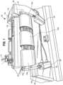
- FIG. 1 is an illustration showing an assembly 102 for an embroidery machine.
- the embroidery machine may be any suitable manufacturing device for embroidering a strand or other material within a textile, and one example (for illustration purposes) is a single or multi-head embroidery machine sold by Barudan America Inc. of Solon, Ohio.
- the embroidery machine includes an embroidery needle 110 for placing an embroidery element, such as the depicted strand 204, on or through a base layer of a textile component 202.
- the embroidery needle 110 locks the strand 204 to the textile component 202 by stitching the strand 204 to and/or through the textile structure of textile component 202 (e.g., through the use of satin-stitches, running-stitches, fill-stitches, or the like).
- Each stitch may utilize a lock-stitch or other suitable structure to enhance securement of the strand 204 to the textile component 202.
- the assembly 102 may be separate from the embroidery machine (as shown), or alternatively it may be built as a portion of the embroidery machine.
- the assembly 102 includes a support device 104 for holding a textile component 202 and an actuation device 108 for moving (e.g., rotating) the textile component 202.
- a housing 114 of the assembly 102 (which may be fixed to the embroidery machine) may have a connection port 116 that connects to the first end 118 of the support device 104.
- the connection port 116 may include a socket, a flange, a series of connection holes (e.g., for bolting or screwing), a clamp, etc.
- the connection port 116 may couple to the support device 104 in a permanent or non-permanent manner.
- the support device 104 may be fixed to the embroidery machine through the port 116.
- “fixed to” means “rigidly attached to” in a permanent or non-permanent manner.
- the actuation device 108 may be fixed to or otherwise coupled to the embroidery machine, but it is also contemplated that the actuation device 108 may simply be placed adjacent to the embroidery machine in an appropriate location for communication with the embroidery machine.
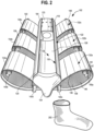
- FIG. 2 is an illustration showing certain components of the assembly of FIG. 1 , including the support device 104 and the actuation device 108.
- the textile component 202 is shown prior to placement on the support device 104.
- the first end 118 of the support device 104 may have a connection adapter 123 for cooperation with the connection port 116 ( FIG. 1 ) of the assembly 102.
- a second end 120 of the support device 104 may include an optional nose element 124.
- the nose element 124 may be advantageous for facilitating the placement of the textile component 202 on the support device 104 by preventing snagging, by progressively stretching the textile component 202 (if necessary), and/or by otherwise guiding the textile component around an outer surface 122 of the support device 104 during deployment.
- the support device 104 may be cylindrical in shape, which is particularly advantageous when the textile component 202 is tubular in shape.
- the textile component 202 may be a circular-knit tubular configuration for use in a variety of applications (e.g., a sock, a glove, a portion of an article of footwear, a portion of an article of apparel, an industrial tubular component, a stent, etc.).
- Other types of textiles are also contemplated, including non-tubular textiles (e.g., flat-knit textiles, flat-woven articles, etc.).
- the support device 104 may be flat or have another suitable shape that corresponds to textiles having a variety of shapes, curvatures, sizes, etc.
- the support device 104 will be described as being generally cylindrical in the remainder of this description.
- the outer surface 122 of the support device is configured (e.g., sized, shaped, and positioned) to receive the textile component 202, and also to contact and support an inner surface of the tubular textile component 202 upon receipt.
- the outer surface 122 of the support device 104 may have a diameter that is about the same size as, or slightly larger than, the inner diameter of the textile component 202 when the textile component 202 is in a relaxed state.
- the diameter of the outer surface 122 may be substantially larger than (e.g., at least 10% larger than) the inner diameter of the relaxed textile component 202 such that the textile component 202 is slightly or substantially stretched when deployed on the support device 104. This may be advantageous when a stretched orientation is desirable during embroidery.
- An opening or window 126 may be present and extend through at least a portion of the outer surface 122 to provide access to a space or cavity 128, and the cavity 128 may be defined by an inner surface 130 of the support device 104.
- the window 126 and cavity 128 are advantageous for providing room for the embroidery needle 110 ( FIG. 1 ) to operate.
- the window 126 may be positioned immediately beneath the embroidery needle such that the embroidery needle avoids contact with the outer surface 122 of the support device 104, and instead extends into the cavity 128, when it pierces the textile component 202.
- Other constructions of the support device 104 are also contemplated to achieve a similar effect (see, e.g., FIGS. 6-7 ).
- the actuation device 108 includes at least one actuation surface 132 (where "132" collectively represents the actuation surfaces 132a, 132b, and 132c).
- the actuation surface 132 at least partially surrounds the support device 104.
- three actuation surfaces 132 are included: a first actuation surface 132a, a second actuation surface 132b, and a third actuation surface 132c.
- Other embodiments may have fewer (e g., one or two) or more (e.g., four, five, or more) actuation surfaces 132.
- the actuation surfaces 132 are movable with respect to the outer surface 122 of the support device 104.
- the first actuation surface 132a is a surface of a first belt 134a, and the first belt 134a is capable of rotating or otherwise cycling such that the first actuation surface 132a moves with respect to the outer surface 122 of the support device 104.
- the second actuation surface 132b may be a surface on a second belt 134b
- the third actuation surface 132c may be a surface on a third belt 134c. More or fewer than three belts 132 may be included (where "132" collectively represents the belts 132a, 132b, and 132c).
- the actuation surface 132a of the first belt 134a is located on a first face 136 of the first belt 134a, and a second face 138 of the first belt 134a (opposite the first face 136) is mechanically coupled to at least one shaft 140 (where "140" represents the shafts 140a, 140b, 140c, and 140d).
- shaft 140 represents the shafts 140a, 140b, 140c, and 140d.
- Four shafts are included: a first shaft 140a, a second shaft 140b, a third shaft 140c, and a fourth shaft 140d.
- At least one of the shafts 140 may include idler-wheels 142 for transmitting the rotation of the shafts 140 into rotation or other cycling motion of the belts 134.
- the second face 138 of the first belt 134a may include grooves 146 that communicate with a set of projections 144 extending from the idler-wheels 142.
- the projections 144 of the idler-wheels 142 may be received by the grooves 146 on the second face 138 of the first belt 134a.
- the second belt 134b and the third belt 134c may also, or alternatively, include grooves and thus also cycle when the shafts 140 rotate.
- the four shafts 140 include two top shafts (e.g., the first shaft 140a and the second shaft 140b) and two bottom shafts (the third shaft 140c and the fourth shaft 140d). More particularly, the first shaft 140a and the second shaft 140b are located on in a first plane (e.g., a plane that is horizontal) and the third shaft 140c and the fourth shaft 140d are located in a lower second plane. The first shaft 140a and the third shaft 140c are located on a right side 148 of the actuation device 108 (from the perspective of FIG. 2 ), and similarly the second shaft 140b and the fourth shaft 140d are located on a left side 150 of the actuation device 108 (from the perspective of FIG. 2 ). These particular locations of the shafts 140 are advantageous for ensuring the support device 104 is adequately surrounded by the actuation surfaces 132 while still providing the embroidery needle with access to the window 126 from above.
- a first plane e.g., a plane that is horizontal
- the shafts 140 may be driven (i.e. , forced into rotation) through any suitable device or method.
- at least one of the shafts 140 may be coupled to a motor. If only one motor is included, the motor may be coupled to only one of the shafts 140 or to multiple shafts 140 (e.g., through a chain or belt drive). In other embodiments, more than one motor may be included (e.g., certain shafts 140 may be associated with separate motors).
- a shaft 140 that is mechanically coupled to a motor (or other rotation-effecting actuator) through something other than the belts 134 themselves is referred to as a "driven shaft.”
- a driven shaft For example, in some non-limiting exemplary embodiments, at least one of the bottom shafts 140c, 140d may be a driven shaft, but the top shafts 140a, 140b may not be.
- rotation of the first shaft 140a and the second shaft 140b may be determined solely by motion of the belts 134.
- This embodiment may be advantageous for allowing the first shaft 140a and the second shaft 140b to be horizontally/vertically movable, as described in more detail below.
- FIG. 3 is an illustration showing the assembly 102, where the textile component 202 is partially deployed on the support device 104.
- the task of placing the textile component 202 on the support device 104 may be performed automatically or by a human operator.
- the textile component 202 may be placed on the support device 104 while the actuation device 108 is in an open state (and see FIG. 4 for an alternative closed state).
- a gap 152 may be located between the actuation surfaces 132 and the support device 104 to provide room for the textile component 202 to slide over the outer surface 122 of the support device 104 during deployment.
- the gap 152 may not be provided, but the belts 134 may be loose enough and/or compliant enough such that the operator can force the belts 134 out of the way as the textile component 202 is deployed over and around outer surface 122 of the support device 104.
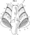
- FIG. 4 is an illustration showing the assembly 102 where the textile component 202 is fully deployed on the support device 104, and where actuation device 108 has transitioned from the open state ( FIG. 3 ) to a closed state.
- the closed state is also referred to as an "engaged state.”
- the belts 134 have two positions (or more): a first position 154 shown in more detail in FIG 3 corresponding to the open state, and a second position 156 as detailed in FIG. 4 corresponding to the closed state.
- the first shaft 140a and the second shaft 140b are displaced upwards and inwards (perhaps along a rotational path), thereby at least partially wrapping the belts 134 around the support device 104.
- An embroidery needle can still access the textile component 202 from above in the closed state.
- the third shaft 140c and the fourth shaft 140d may also move, but in other embodiments, the third shaft 140c and the fourth shaft 140d may remain in the same respective positions in both the open and closed states, particularly when they are coupled to one or more immovable actuators (e.g., motors).
- immovable actuators e.g., motors
- FIG. 1 One embodiment for providing control of the shaft position is shown in FIG. 1 .
- the shafts 140a and 140c may be coupled to a linear actuator 158 (or another suitable actuation device) through a linkage 160.
- the linkage 160 may also provide support to an end 162 of the shafts 140a and 140c, and the shafts 140a and 140c may be rotatable with respect to the linkage 160 about their respective longitudinal axes.
- the linkage 160 is also optionally rotatable with respect to an actuation arm 164 of the linear actuator 158. When the actuation arm 164 of the linear actuator 158 extends upward, it may force the linkage 160 upward, which will also force the shafts 140a and 140c upward.
- the shafts 140a and 140c will reposition a portion of the belts 134 such that the belts 134 are partially wrapped and tensioned around the support device 104.
- This tension in the belts 134 may provide sufficient engagement between the actuation surfaces 132 and a textile component held on the support device 104, as described above.
- the linkage 160 is coupled to the first shaft 140a and the third shaft 140c.
- the lower shafts i.e. , the third shaft 140c and fourth shaft 140d
- the linkages 160 may not move when the linkages 160 move. This may be advantageous when the lower shafts 140c, and 140d are drive shafts that are coupled to a motor or other actuator, since a common location among different states (e.g. open and closed states) prevents the need to also move the associated motor or other actuator with the drive shafts.
- the degree of extension of the actuation arm 164 may also be variable, which may allow for one or more intermediate states between the open state and the closed state.
- the actuation device 108 may be capable of adapting to two or more different support devices 104 having different dimensions, and/or different belts 134.
- more than one linear actuator 158 may be included.
- a second linear actuator 159 may be included to assist with shaft positioning.
- one or more linear actuators may be included on the other side of the assembly 102 and coupled to one or more of the second shaft 140b and the fourth shaft 140d through separate linkages.
- the linear actuator(s) may be controlled automatically (e g., via a control device) or manually (e.g., by pushing a button to activate the linear actuator, or by manually forcing the actuation arm 164 vertically).
- the closed state provides suitable contact or other engagement, and therefore friction, between the actuation surfaces 132 and the textile component 202.
- the total static friction between the actuation surfaces 132 and the textile component 202 is greater than the total static friction between the outer surface 122 of the support device 104 and the textile component 202.
- the textile component 202 remains static (i.e., substantially lacking relative motion) with respect to the actuation surfaces 132, but will slip and therefore rotate with respect to the outer surface 122 of the support device 104. Rotation/cycling of the belts 134 will therefore cause rotation of the textile component 202 with respect to the embroidery machine.
- the ability to rotate of the textile component 202 provides an embroidery needle with access to areas of the textile component 202 that would not otherwise be reachable if the textile component 202 was stationary.
- embroidery needles can typically only move vertically and axially, and they cannot rotate around a tubular textile component to gain access to locations 360 degrees around the entirety of the textile surface.
- the present embodiments overcome this shortcoming by providing an apparatus and method that is capable of moving/rotating the textile with respect to the embroidery needle, and therefore providing 360 degree access to surfaces of the textile. Notably, this 360 degree access is provided without necessitating human intervention during the embroidery process and without additional machine-setup steps (and therefore without substantially compromising manufacturing efficiency).
- the belts 134 may be capable of cycling in a first direction 166 and also a second direction 168. Switching the direction of rotation may be accomplished by switching the direction of rotation of the driven shaft(s), and/or by switching which shaft 140 provides the driving force. For example, if one motor is used (or multiple motors are operating in parallel), the direction of rotation may be switched by simply changing the direction of motor rotation. In other embodiments, one of the shafts 140 may be coupled to a first motor configured to drive rotation in the first direction 166, and a different one of the shafts 140 may be coupled to a different motor configured to drive rotation in the second direction 168.
- switching the direction of rotation may be accomplished simply by switching which motor provides the driving force (e.g., by turning one motor off and activating another).
- these embodiments may prevent the need for a multi-directional motor, which may decrease the complexity of the control system and reduce the expense of the assembly 102.
- the rotation direction may be switched during the embroidery process, which allows the formation of zig-zag patterns and other patterns where the embroidered strand 204 varies in its stitch direction. This may provide the capability of creating complex embroidery patterns through controlling rotation of the textile component 202 while simultaneously controlling the operation of the embroidery needle.
- the assembly 102 may be automatically controlled (e.g., through a programmed control system) and/or manually controlled (through an interface providing control capabilities to a human operator). If automatically controlled, the same control system may operate both the embroidery needle and the assembly 102, or separate control systems may be used.
- the support device 104 may be separable from the actuation device 108.
- the first end 118 of the support device 104 may include the connection adapter 123 that connects to the assembly's port 116 (see FIG. 1 ).
- the connection adapter 123 may be removable from the port 116 ( FIG. 1 ) such that the support device 104 can be handled independently.
- the connection adapter 123 may also be configured to attach to another textile manufacturing machine.
- the support device 104 may therefore be movable to another manufacturing process while retaining a textile component.
- a heat-application device may also include a port for receiving the connection adapter 123, and the textile component may therefore be moved from the embroidery machine to the heat application device, and then heat-treated, while under continuous support provided by the support device 104.
- an operator may place the textile component on the support device 104 while the support device 104 is separated from the actuation device 108, and then move the support device 104 into engagement with the actuation device 108. This may be a preferred method when it is difficult to place the textile component on the support device 104 when engaged with the actuation device 108, even when/if the actuation device 108 is in the above-described open state.
- the present embodiments also provide the assembly 100 with the ability to efficiently switch between different support devices 104.
- different support devices 104 may have different dimensions (e.g., diameter, length, etc.) for receiving different sized textile components. Since the support devices 104 may have an identical or similar connection adapter 123, a certain support device 104 may be quickly and efficiently selected and placed into communication with the remainder of the assembly 102 without substantially adjusting anything else.
- FIG. 6 and FIG. 7 are illustrations showing additional embodiments of support devices for use with the assembly 102 described above.
- a support device 306 may include a central support shaft 370 that extends from a first end 318 to a second end 320.
- the central support shaft 370 may couple a connection adapter 323 to a nose element 324.
- the connection adapter 323 may be similar to the connection adapter 123 (of FIG. 2 ), and thus it is contemplated that the port 116 ( FIG. 1 ) may be capable of receiving both support-device types. Still referring to FIG.
- the central support shaft 370 when a textile component is deployed over the nose element 324 and extends to the connection adapter 323, the central support shaft 370 may be spaced from the textile component 202 since it is radially separated from an outer-diameter surface 374 of the nose element 324 and also from an outer-diameter surface 372 of the connection adapter 323.
- a gap or cavity 328 may therefore be defined between the textile component and the central support shaft 370 when the textile component is deployed, and the gap or cavity 328 may provide the requisite space needed for communication with an embroidery needle.
- FIG. 6 may further be advantageous since the support device 104 itself could rotate with respect to an embroidery needle, which may provide rotation of a textile component with respect to an embroidery needle without using the actuation device 108 (of FIG. 1 ).
- the port 116 FIG. 1
- the support device 104 may rotate with respect to the remainder of the machine, thereby causing the support device 104 to rotate.
- the lack of any support device near or in contact with the textile component 202 along the majority of the length of the support device 104 may make this feasible since there will be nothing lining the inner surface of the textile component that may contact the embroidery needle to interfere with its operation.
- FIG. 7 shows another embodiment of a support device 406, where a nose element 424 is connected to a connection adapter 423 via support shafts 470 located at or near the outer diameter of the support device 406.
- This embodiment may be advantageous since the support shafts 470 may provide support and/or tension to the textile component along its length (e.g., through direct contact), particularly when it is desirable for the textile component to be in a stretched state during embroidery.
- the embodiment described above with a window 126 may provide support/tension to the textile component along the entire length of the support device 104.
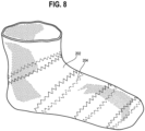
- FIG. 8 is an illustration showing the textile component 202 with the embroidered strand 204 after being removed from the above-described assembly.
- the embroidered strand 204 may extend at least 360 degrees around the tubular construction of the textile component 202.
- the embroidered strand 204 may be advantageous not only for its aesthetics, but it also may provide the textile component with desirable physical properties, such as a desired rigidity, selected stretchability (which may vary in different directions), etc.
- desirable physical properties such as a desired rigidity, selected stretchability (which may vary in different directions), etc.
- the assembly 102 described above makes this 360 degree extension of an embroidered strand 204 on a textile component possible without significantly increasing the manufacturing burden.
- the above-described embodiments may enable formation of the textile component 202 using conventional embroidery needles and conventional embroidery processes without substantial modification of the embroidery needle and/or machine.
Landscapes
- Engineering & Computer Science (AREA)
- Textile Engineering (AREA)
- Sewing Machines And Sewing (AREA)
Claims (10)
- Ensemble (102) pour une machine à broder, comprenant :un dispositif de support (104) qui présente une surface (122) pour la réception d'un composant textile (202) ; etun dispositif d'actionnement (108), le dispositif d'actionnement (108) présentant au moins une surface d'actionnement (132) qui entoure au moins partiellement le dispositif de support (104), la surface d'actionnement étant une première face (136) d'une courroie (134) apte à tourner ou à se déplacer autrement de manière cyclique, de sorte que la surface d'actionnement (132) est mobile par rapport à la surface (122) du dispositif de support (104) de sorte que, lorsque le composant textile (202) est retenu par le dispositif de support (104), un déplacement de la surface d'actionnement (132) par rapport à la surface (122) du dispositif de support (104) entraîne un déplacement du composant textile (202) par rapport à la surface (122) du dispositif de support (104),une deuxième face (138) de la courroie étant mécaniquement couplée à au moins un arbre (140),l'ensemble étant caractérisé en ce qu'il comprend un premier arbre (140a) et un deuxième arbre (140b) agencés dans un premier plan horizontal, l'ensemble comprenant un troisième arbre (140c) et un quatrième arbre (140d) agencés dans un deuxième plan horizontal, le premier arbre (140a) et le troisième arbre (140c) étant agencés d'un côté droit du dispositif d'actionnement (108), le deuxième arbre (140b) et le quatrième arbre (140d) étant agencés d'un côté gauche du dispositif d'actionnement (108),le dispositif d'actionnement (108) étant réalisé de manière à se déplacer d'un état ouvert à un état fermé en déplaçant le premier arbre (140a) et le deuxième arbre (140b) vers le haut et le bas, enroulant ainsi la courroie (134) qui fournit la surface d'actionnement (132) autour du dispositif de support (104),et l'état fermé fournissant un contact approprié ou un autre engagement et ainsi une friction entre la surface d'actionnement (132) et le composant textile (202) pour provoquer une rotation du composant textile (202) par rapport à la surface (122) du dispositif de support (104) en entraînant au moins un arbre (140a, 140b, 140c, 140d) en rotation.
- Ensemble (102) selon la revendication 1, le dispositif de support (104) présentant une fenêtre (126) qui définit une cavité (128), et la surface (122) du dispositif de support (104) entourant au moins partiellement la cavité (128).
- Ensemble (102) selon la revendication 2, le dispositif de support (104) étant fixé en place par rapport à une machine à broder qui comprend une aiguille à broder (110), et l'aiguille à broder (110) étant apte à s'étendre dans la cavité (128) du dispositif de support (104) lorsque l'aiguille à broder (110) perfore le composant textile (202).
- Ensemble (102) selon la revendication 1, la surface d'actionnement (132) présentant un état engagé et un état ouvert, la surface d'actionnement (132) entourant au moins partiellement le dispositif de support (104) à l'état engagé pour provoquer un déplacement d'un composant textile (202) retenu par le dispositif de support (104), et au moins une partie de la surface d'actionnement (132) se déplaçant en éloignement du dispositif de support (104) lors de la transition de l'état engagé à l'état ouvert.
- Ensemble (102) selon la revendication 4, comprenant en outre un arbre mobile (140a), un déplacement de l'arbre mobile (140a) entraînant une transition de la surface d'actionnement (132) entre l'état engagé et l'état ouvert.
- Ensemble (102) selon la revendication 5, comprenant en outre un deuxième arbre (140b) qui est mécaniquement couplé à la surface d'actionnement (132), le deuxième arbre (140b) étant entraîné par un moteur.
- Ensemble (102) selon la revendication 1, le dispositif d'actionnement (108) présentant une courroie (134a), et une première face (136) de la courroie (134a) définissant au moins une partie de la surface d'actionnement (132).
- Ensemble (102) selon la revendication 7, comprenant en outre une deuxième courroie (134b) qui présente une deuxième surface d'actionnement (132).
- Ensemble (102) selon la revendication 7, la courroie (134a) présentant une deuxième face (138) qui est opposée à la première face (136), et la deuxième face (138) présentant une pluralité de rainures (146).
- Ensemble (102) selon la revendication 1, le dispositif de support (104) étant couplé à une ouverture de connexion (116) d'un boîtier (114) de l'ensemble (102) par l'intermédiaire d'un adaptateur de connexion (123), et l'adaptateur de connexion (123) étant apte à être retiré de l'ouverture de connexion (116) de l'ensemble (102) de sorte que le dispositif de support (104) est apte à être séparé du dispositif d'actionnement (108).
Applications Claiming Priority (3)
| Application Number | Priority Date | Filing Date | Title |
|---|---|---|---|
| US201862657179P | 2018-04-13 | 2018-04-13 | |
| EP19721440.6A EP3775349B1 (fr) | 2018-04-13 | 2019-04-11 | Ensembles pour la fabrication de textiles, et procédés associés |
| PCT/US2019/026900 WO2019200041A1 (fr) | 2018-04-13 | 2019-04-11 | Ensembles pour la fabrication de textiles, et procédés associés |
Related Parent Applications (1)
| Application Number | Title | Priority Date | Filing Date |
|---|---|---|---|
| EP19721440.6A Division EP3775349B1 (fr) | 2018-04-13 | 2019-04-11 | Ensembles pour la fabrication de textiles, et procédés associés |
Publications (2)
| Publication Number | Publication Date |
|---|---|
| EP4050143A1 EP4050143A1 (fr) | 2022-08-31 |
| EP4050143B1 true EP4050143B1 (fr) | 2024-12-25 |
Family
ID=66380149
Family Applications (2)
| Application Number | Title | Priority Date | Filing Date |
|---|---|---|---|
| EP22153144.5A Active EP4050143B1 (fr) | 2018-04-13 | 2019-04-11 | Ensembles de fabrication textile et procédés associés |
| EP19721440.6A Active EP3775349B1 (fr) | 2018-04-13 | 2019-04-11 | Ensembles pour la fabrication de textiles, et procédés associés |
Family Applications After (1)
| Application Number | Title | Priority Date | Filing Date |
|---|---|---|---|
| EP19721440.6A Active EP3775349B1 (fr) | 2018-04-13 | 2019-04-11 | Ensembles pour la fabrication de textiles, et procédés associés |
Country Status (5)
| Country | Link |
|---|---|
| US (1) | US11591733B2 (fr) |
| EP (2) | EP4050143B1 (fr) |
| CN (1) | CN111989432B (fr) |
| TW (1) | TWM590163U (fr) |
| WO (1) | WO2019200041A1 (fr) |
Families Citing this family (1)
| Publication number | Priority date | Publication date | Assignee | Title |
|---|---|---|---|---|
| CN112853627A (zh) * | 2021-01-08 | 2021-05-28 | 广州市宗顺服装贸易有限公司 | 一种针织运动羊毛面料及加工系统与加工方法 |
Family Cites Families (30)
| Publication number | Priority date | Publication date | Assignee | Title |
|---|---|---|---|---|
| US905247A (en) * | 1907-07-08 | 1908-12-01 | Samuel Veit Swoboda | Stretching-frame for embroidering sewing-machines. |
| US1583590A (en) * | 1921-03-24 | 1926-05-04 | Paramount Textile Mach Co | Hosiery drying and shaping form |
| US2330757A (en) * | 1940-11-22 | 1943-09-28 | Harold E Stout | Hosiery forming and drying device |
| US3050106A (en) * | 1958-03-03 | 1962-08-21 | Johns Manville | Method and apparatus for forming pipe insulation |
| US3129535A (en) * | 1962-04-25 | 1964-04-21 | Chemetron Corp | Method and apparatus for grinding rails |
| US3395044A (en) * | 1967-09-21 | 1968-07-30 | Shoeld Mark | Lead acid storage battery of the jelly-roll type |
| BE755902A (fr) * | 1969-09-11 | 1971-02-15 | Bemberg Ag | Dispositif pour le traitement continu de bandes de pellicules ( |
| US4099401A (en) * | 1977-06-27 | 1978-07-11 | The Gates Rubber Company | Method of producing spirally wound electrochemical cells |
| IT1205383B (it) * | 1983-04-11 | 1989-03-15 | Rosso Ind Spa | Dispositivo rivoltacalze |
| US4691400A (en) * | 1983-06-09 | 1987-09-08 | Arneson Howard M | Article buffing apparatus and method |
| JPS6112965A (ja) * | 1984-06-22 | 1986-01-21 | 株式会社 タカトリ機械製作所 | 足型に插着された靴下つま先部の位置修正装置 |
| JPH06304365A (ja) * | 1993-04-21 | 1994-11-01 | Pegasus Sewing Mach Mfg Co Ltd | 筒状生地の自動ヘミング装置 |
| US5553560A (en) * | 1993-10-08 | 1996-09-10 | Tokai Kogyo Mishin Kabushiki Kaisha | Sewing machine and work fabric holder device thereof |
| JP3122589B2 (ja) * | 1994-12-29 | 2001-01-09 | 株式会社タカトリ | パンティストッキング素材の装着方法 |
| FR2734285B1 (fr) * | 1995-05-17 | 1997-06-13 | Icbt Perfojet Sa | Procede pour la fabrication d'une nappe textile non tissee par jets d'eau sous pression, et installation pour la mise en oeuvre de ce procede |
| US5642601A (en) * | 1995-11-28 | 1997-07-01 | Greenwood Mills, Inc. | Method of forming thermal insulation |
| IT1316384B1 (it) * | 2000-04-07 | 2003-04-10 | S R A S R L | Metodo ed apparecchiatura per apertura, posizionamento e caricamentosu forme di calzini, gambaletti e simili. |
| IT1316568B1 (it) * | 2000-08-31 | 2003-04-24 | Gianfranco Bagni | Metodo e dispositivo per l'orientamento automatico di articoli dicalzetteria quali calzini, gambaletti o simili. |
| EP1857582B1 (fr) * | 2006-05-18 | 2008-12-24 | Santoni S.p.A. | Dispositif automatique et méthode pour orienter un article textile sur un support |
| CN101525818B (zh) * | 2009-04-01 | 2013-06-05 | 中捷缝纫机股份有限公司 | 缝纫机拖布装置 |
| DE102009041177A1 (de) * | 2009-09-11 | 2011-03-24 | Rwth Aachen | Verfahren zum Herstellen von dreidimensionalen Faserverbundbauteilen und Halterung hierfür |
| WO2011033969A1 (fr) * | 2009-09-17 | 2011-03-24 | エヌエスディ株式会社 | Dispositif d'entraînement pour cousoir de machine à coudre |
| IT1399321B1 (it) * | 2010-04-09 | 2013-04-16 | Savmik S R L | Macchina per il ricamo di un articolo |
| WO2011152346A1 (fr) * | 2010-06-04 | 2011-12-08 | 株式会社瑞光 | Dispositif de pliage, système de pliage, et procédé de pliage pour des articles portables jetables |
| US8978567B2 (en) * | 2011-01-28 | 2015-03-17 | Orisol Asia Ltd. | Sewing direction control apparatus for sewing machine |
| JP2014138628A (ja) * | 2011-09-16 | 2014-07-31 | Midori Anzen Co Ltd | ミシン、縫製物及びステントグラフト |
| JP2015158028A (ja) * | 2014-02-25 | 2015-09-03 | ブラザー工業株式会社 | 刺繍枠、及びミシン |
| US9840260B2 (en) * | 2014-04-24 | 2017-12-12 | Meteorcomm Llc | Systems and methods for using a railroad rail as radiating element for transmitting wireless communications signals |
| US10508373B2 (en) | 2016-05-13 | 2019-12-17 | Nike, Inc. | Embroidered article |
| CN107630299B (zh) * | 2017-09-05 | 2023-02-14 | 福建省华科模具科技有限公司 | 一种袜子前掌端口缝合机 |
-
2019
- 2019-04-11 EP EP22153144.5A patent/EP4050143B1/fr active Active
- 2019-04-11 CN CN201980025597.6A patent/CN111989432B/zh active Active
- 2019-04-11 WO PCT/US2019/026900 patent/WO2019200041A1/fr not_active Ceased
- 2019-04-11 EP EP19721440.6A patent/EP3775349B1/fr active Active
- 2019-04-12 TW TW108204488U patent/TWM590163U/zh unknown
- 2019-04-12 US US16/383,299 patent/US11591733B2/en active Active
Also Published As
| Publication number | Publication date |
|---|---|
| US11591733B2 (en) | 2023-02-28 |
| US20190316285A1 (en) | 2019-10-17 |
| EP3775349A1 (fr) | 2021-02-17 |
| CN111989432A (zh) | 2020-11-24 |
| CN111989432B (zh) | 2022-08-02 |
| EP4050143A1 (fr) | 2022-08-31 |
| EP3775349B1 (fr) | 2022-02-09 |
| TWM590163U (zh) | 2020-02-01 |
| WO2019200041A1 (fr) | 2019-10-17 |
Similar Documents
| Publication | Publication Date | Title |
|---|---|---|
| TWI339229B (en) | Circular knitting machine | |
| US6957615B1 (en) | Method and device to apply cord thread or ribbons onto fabrics in a quilting machine | |
| EP4050143B1 (fr) | Ensembles de fabrication textile et procédés associés | |
| KR920004241B1 (ko) | 팬티스타킹등과 같은 복수개의 관형편물제품을 동시에 제조하기 위한 원형편물기 | |
| CN107268166B (zh) | 缝合装置以及包括所述缝合装置的机器 | |
| ES2718375T3 (es) | Máquina de acolchado de múltiples agujas y un método de acolchado correspondiente | |
| EP2430226B1 (fr) | Machine à broder | |
| EP1847640B1 (fr) | Machine à coudre multifonction conçue pour coudre des tissus en utilisant différents agencements et types de points | |
| CN105862262B (zh) | 一梭多针缝纫封边装置 | |
| EP1472399A1 (fr) | Dispositif et procede d'application de paillettes sur des tissus dans une machine a coudre, et machine a coudre a aiguilles multiples | |
| JPH02277862A (ja) | 編み機の針を選択し制御するための機構、編み機のための針、および編み機 | |
| CZ18934U1 (cs) | Maloprumerový pletací stroj | |
| KR20080000510A (ko) | 단추달이 재봉기 | |
| KR101951200B1 (ko) | 2-실 본봉 회전 루퍼를 가지는 단일 헤드 또는 다중 헤드 자수 기계 | |
| EP1006229A1 (fr) | Machine à piquer à aiguilles multiples pour piquer/coudre des points noués et/ou points de chainette doubles | |
| WO2003025273A1 (fr) | Procede et dispositif pour changer de couleur de fil sur un metier a matelasser ou a broder, et metier ainsi equipe | |
| EP3655578B1 (fr) | Machine à coudre pour coutures décoratives et fonctionnelles | |
| CZ308429B6 (cs) | Způsob šití imitací rukávových dírek dvěma různými nitěmi dvoujehlovým šicím strojem se dvěma jehelními tyčemi a zařízení k jeho provádění | |
| EP4476393A1 (fr) | Système de blocage de couture pour machines à coudre | |
| KR101052505B1 (ko) | 자수기계의 바늘 선택 제어 장치 | |
| EP2508663B1 (fr) | Machine à coudre avec un dispositif pour échanger la bobine | |
| KR200370201Y1 (ko) | 직물 표면용 루프 또는 파일 형성 장치 | |
| CN114026279A (zh) | 用于制造平脚裤的机器 | |
| JPH09239168A (ja) | 縫着用ミシン | |
| CN108026682A (zh) | 多针链式针迹缝纫机 |
Legal Events
| Date | Code | Title | Description |
|---|---|---|---|
| PUAI | Public reference made under article 153(3) epc to a published international application that has entered the european phase |
Free format text: ORIGINAL CODE: 0009012 |
|
| STAA | Information on the status of an ep patent application or granted ep patent |
Free format text: STATUS: THE APPLICATION HAS BEEN PUBLISHED |
|
| AC | Divisional application: reference to earlier application |
Ref document number: 3775349 Country of ref document: EP Kind code of ref document: P |
|
| AK | Designated contracting states |
Kind code of ref document: A1 Designated state(s): AL AT BE BG CH CY CZ DE DK EE ES FI FR GB GR HR HU IE IS IT LI LT LU LV MC MK MT NL NO PL PT RO RS SE SI SK SM TR |
|
| STAA | Information on the status of an ep patent application or granted ep patent |
Free format text: STATUS: REQUEST FOR EXAMINATION WAS MADE |
|
| 17P | Request for examination filed |
Effective date: 20230228 |
|
| RBV | Designated contracting states (corrected) |
Designated state(s): AL AT BE BG CH CY CZ DE DK EE ES FI FR GB GR HR HU IE IS IT LI LT LU LV MC MK MT NL NO PL PT RO RS SE SI SK SM TR |
|
| P01 | Opt-out of the competence of the unified patent court (upc) registered |
Effective date: 20230515 |
|
| GRAP | Despatch of communication of intention to grant a patent |
Free format text: ORIGINAL CODE: EPIDOSNIGR1 |
|
| STAA | Information on the status of an ep patent application or granted ep patent |
Free format text: STATUS: GRANT OF PATENT IS INTENDED |
|
| INTG | Intention to grant announced |
Effective date: 20240719 |
|
| GRAS | Grant fee paid |
Free format text: ORIGINAL CODE: EPIDOSNIGR3 |
|
| GRAA | (expected) grant |
Free format text: ORIGINAL CODE: 0009210 |
|
| STAA | Information on the status of an ep patent application or granted ep patent |
Free format text: STATUS: THE PATENT HAS BEEN GRANTED |
|
| AC | Divisional application: reference to earlier application |
Ref document number: 3775349 Country of ref document: EP Kind code of ref document: P |
|
| AK | Designated contracting states |
Kind code of ref document: B1 Designated state(s): AL AT BE BG CH CY CZ DE DK EE ES FI FR GB GR HR HU IE IS IT LI LT LU LV MC MK MT NL NO PL PT RO RS SE SI SK SM TR |
|
| REG | Reference to a national code |
Ref country code: GB Ref legal event code: FG4D |
|
| REG | Reference to a national code |
Ref country code: CH Ref legal event code: EP |
|
| REG | Reference to a national code |
Ref country code: DE Ref legal event code: R096 Ref document number: 602019064126 Country of ref document: DE |
|
| REG | Reference to a national code |
Ref country code: IE Ref legal event code: FG4D |
|
| REG | Reference to a national code |
Ref country code: LT Ref legal event code: MG9D |
|
| PG25 | Lapsed in a contracting state [announced via postgrant information from national office to epo] |
Ref country code: HR Free format text: LAPSE BECAUSE OF FAILURE TO SUBMIT A TRANSLATION OF THE DESCRIPTION OR TO PAY THE FEE WITHIN THE PRESCRIBED TIME-LIMIT Effective date: 20241225 |
|
| PG25 | Lapsed in a contracting state [announced via postgrant information from national office to epo] |
Ref country code: FI Free format text: LAPSE BECAUSE OF FAILURE TO SUBMIT A TRANSLATION OF THE DESCRIPTION OR TO PAY THE FEE WITHIN THE PRESCRIBED TIME-LIMIT Effective date: 20241225 |
|
| PG25 | Lapsed in a contracting state [announced via postgrant information from national office to epo] |
Ref country code: BG Free format text: LAPSE BECAUSE OF FAILURE TO SUBMIT A TRANSLATION OF THE DESCRIPTION OR TO PAY THE FEE WITHIN THE PRESCRIBED TIME-LIMIT Effective date: 20241225 |
|
| PG25 | Lapsed in a contracting state [announced via postgrant information from national office to epo] |
Ref country code: NO Free format text: LAPSE BECAUSE OF FAILURE TO SUBMIT A TRANSLATION OF THE DESCRIPTION OR TO PAY THE FEE WITHIN THE PRESCRIBED TIME-LIMIT Effective date: 20250325 |
|
| PG25 | Lapsed in a contracting state [announced via postgrant information from national office to epo] |
Ref country code: GR Free format text: LAPSE BECAUSE OF FAILURE TO SUBMIT A TRANSLATION OF THE DESCRIPTION OR TO PAY THE FEE WITHIN THE PRESCRIBED TIME-LIMIT Effective date: 20250326 Ref country code: LV Free format text: LAPSE BECAUSE OF FAILURE TO SUBMIT A TRANSLATION OF THE DESCRIPTION OR TO PAY THE FEE WITHIN THE PRESCRIBED TIME-LIMIT Effective date: 20241225 |
|
| PG25 | Lapsed in a contracting state [announced via postgrant information from national office to epo] |
Ref country code: RS Free format text: LAPSE BECAUSE OF FAILURE TO SUBMIT A TRANSLATION OF THE DESCRIPTION OR TO PAY THE FEE WITHIN THE PRESCRIBED TIME-LIMIT Effective date: 20250325 |
|
| REG | Reference to a national code |
Ref country code: NL Ref legal event code: MP Effective date: 20241225 |
|
| PG25 | Lapsed in a contracting state [announced via postgrant information from national office to epo] |
Ref country code: NL Free format text: LAPSE BECAUSE OF FAILURE TO SUBMIT A TRANSLATION OF THE DESCRIPTION OR TO PAY THE FEE WITHIN THE PRESCRIBED TIME-LIMIT Effective date: 20241225 |
|
| REG | Reference to a national code |
Ref country code: DE Ref legal event code: R082 Ref document number: 602019064126 Country of ref document: DE Representative=s name: MUELLER-BORE & PARTNER PATENTANWAELTE PARTG MB, DE |
|
| REG | Reference to a national code |
Ref country code: AT Ref legal event code: MK05 Ref document number: 1754230 Country of ref document: AT Kind code of ref document: T Effective date: 20241225 |
|
| PG25 | Lapsed in a contracting state [announced via postgrant information from national office to epo] |
Ref country code: SM Free format text: LAPSE BECAUSE OF FAILURE TO SUBMIT A TRANSLATION OF THE DESCRIPTION OR TO PAY THE FEE WITHIN THE PRESCRIBED TIME-LIMIT Effective date: 20241225 |
|
| PG25 | Lapsed in a contracting state [announced via postgrant information from national office to epo] |
Ref country code: PL Free format text: LAPSE BECAUSE OF FAILURE TO SUBMIT A TRANSLATION OF THE DESCRIPTION OR TO PAY THE FEE WITHIN THE PRESCRIBED TIME-LIMIT Effective date: 20241225 |
|
| PGFP | Annual fee paid to national office [announced via postgrant information from national office to epo] |
Ref country code: DE Payment date: 20250214 Year of fee payment: 7 |
|
| PG25 | Lapsed in a contracting state [announced via postgrant information from national office to epo] |
Ref country code: ES Free format text: LAPSE BECAUSE OF FAILURE TO SUBMIT A TRANSLATION OF THE DESCRIPTION OR TO PAY THE FEE WITHIN THE PRESCRIBED TIME-LIMIT Effective date: 20241225 |
|
| PG25 | Lapsed in a contracting state [announced via postgrant information from national office to epo] |
Ref country code: IS Free format text: LAPSE BECAUSE OF FAILURE TO SUBMIT A TRANSLATION OF THE DESCRIPTION OR TO PAY THE FEE WITHIN THE PRESCRIBED TIME-LIMIT Effective date: 20250425 |
|
| PG25 | Lapsed in a contracting state [announced via postgrant information from national office to epo] |
Ref country code: PT Free format text: LAPSE BECAUSE OF FAILURE TO SUBMIT A TRANSLATION OF THE DESCRIPTION OR TO PAY THE FEE WITHIN THE PRESCRIBED TIME-LIMIT Effective date: 20250428 |
|
| PG25 | Lapsed in a contracting state [announced via postgrant information from national office to epo] |
Ref country code: EE Free format text: LAPSE BECAUSE OF FAILURE TO SUBMIT A TRANSLATION OF THE DESCRIPTION OR TO PAY THE FEE WITHIN THE PRESCRIBED TIME-LIMIT Effective date: 20241225 |
|
| PG25 | Lapsed in a contracting state [announced via postgrant information from national office to epo] |
Ref country code: AT Free format text: LAPSE BECAUSE OF FAILURE TO SUBMIT A TRANSLATION OF THE DESCRIPTION OR TO PAY THE FEE WITHIN THE PRESCRIBED TIME-LIMIT Effective date: 20241225 Ref country code: RO Free format text: LAPSE BECAUSE OF FAILURE TO SUBMIT A TRANSLATION OF THE DESCRIPTION OR TO PAY THE FEE WITHIN THE PRESCRIBED TIME-LIMIT Effective date: 20241225 |
|
| PG25 | Lapsed in a contracting state [announced via postgrant information from national office to epo] |
Ref country code: SK Free format text: LAPSE BECAUSE OF FAILURE TO SUBMIT A TRANSLATION OF THE DESCRIPTION OR TO PAY THE FEE WITHIN THE PRESCRIBED TIME-LIMIT Effective date: 20241225 |
|
| PG25 | Lapsed in a contracting state [announced via postgrant information from national office to epo] |
Ref country code: CZ Free format text: LAPSE BECAUSE OF FAILURE TO SUBMIT A TRANSLATION OF THE DESCRIPTION OR TO PAY THE FEE WITHIN THE PRESCRIBED TIME-LIMIT Effective date: 20241225 |
|
| PG25 | Lapsed in a contracting state [announced via postgrant information from national office to epo] |
Ref country code: IT Free format text: LAPSE BECAUSE OF FAILURE TO SUBMIT A TRANSLATION OF THE DESCRIPTION OR TO PAY THE FEE WITHIN THE PRESCRIBED TIME-LIMIT Effective date: 20241225 |
|
| PG25 | Lapsed in a contracting state [announced via postgrant information from national office to epo] |
Ref country code: SE Free format text: LAPSE BECAUSE OF FAILURE TO SUBMIT A TRANSLATION OF THE DESCRIPTION OR TO PAY THE FEE WITHIN THE PRESCRIBED TIME-LIMIT Effective date: 20241225 |
|
| REG | Reference to a national code |
Ref country code: DE Ref legal event code: R097 Ref document number: 602019064126 Country of ref document: DE |
|
| PG25 | Lapsed in a contracting state [announced via postgrant information from national office to epo] |
Ref country code: DK Free format text: LAPSE BECAUSE OF FAILURE TO SUBMIT A TRANSLATION OF THE DESCRIPTION OR TO PAY THE FEE WITHIN THE PRESCRIBED TIME-LIMIT Effective date: 20241225 |
|
| PLBE | No opposition filed within time limit |
Free format text: ORIGINAL CODE: 0009261 |
|
| STAA | Information on the status of an ep patent application or granted ep patent |
Free format text: STATUS: NO OPPOSITION FILED WITHIN TIME LIMIT |
|
| REG | Reference to a national code |
Ref country code: CH Ref legal event code: L10 Free format text: ST27 STATUS EVENT CODE: U-0-0-L10-L00 (AS PROVIDED BY THE NATIONAL OFFICE) Effective date: 20251105 |
|
| REG | Reference to a national code |
Ref country code: CH Ref legal event code: H13 Free format text: ST27 STATUS EVENT CODE: U-0-0-H10-H13 (AS PROVIDED BY THE NATIONAL OFFICE) Effective date: 20251125 |
|
| 26N | No opposition filed |
Effective date: 20250926 |
|
| PG25 | Lapsed in a contracting state [announced via postgrant information from national office to epo] |
Ref country code: LU Free format text: LAPSE BECAUSE OF NON-PAYMENT OF DUE FEES Effective date: 20250411 |
|
| PG25 | Lapsed in a contracting state [announced via postgrant information from national office to epo] |
Ref country code: MC Free format text: LAPSE BECAUSE OF FAILURE TO SUBMIT A TRANSLATION OF THE DESCRIPTION OR TO PAY THE FEE WITHIN THE PRESCRIBED TIME-LIMIT Effective date: 20241225 |
|
| REG | Reference to a national code |
Ref country code: BE Ref legal event code: MM Effective date: 20250430 |
|
| PG25 | Lapsed in a contracting state [announced via postgrant information from national office to epo] |
Ref country code: BE Free format text: LAPSE BECAUSE OF NON-PAYMENT OF DUE FEES Effective date: 20250430 |
|
| PG25 | Lapsed in a contracting state [announced via postgrant information from national office to epo] |
Ref country code: CH Free format text: LAPSE BECAUSE OF NON-PAYMENT OF DUE FEES Effective date: 20250430 |
|
| PGFP | Annual fee paid to national office [announced via postgrant information from national office to epo] |
Ref country code: GB Payment date: 20260219 Year of fee payment: 8 |
|
| PG25 | Lapsed in a contracting state [announced via postgrant information from national office to epo] |
Ref country code: IE Free format text: LAPSE BECAUSE OF NON-PAYMENT OF DUE FEES Effective date: 20250411 |
|
| PGFP | Annual fee paid to national office [announced via postgrant information from national office to epo] |
Ref country code: FR Payment date: 20260209 Year of fee payment: 8 |