EP4050188B1 - Système de porte pour au moins une porte - Google Patents
Système de porte pour au moins une porte Download PDFInfo
- Publication number
- EP4050188B1 EP4050188B1 EP21159073.2A EP21159073A EP4050188B1 EP 4050188 B1 EP4050188 B1 EP 4050188B1 EP 21159073 A EP21159073 A EP 21159073A EP 4050188 B1 EP4050188 B1 EP 4050188B1
- Authority
- EP
- European Patent Office
- Prior art keywords
- door
- control unit
- drive
- motor
- door system
- Prior art date
- Legal status (The legal status is an assumption and is not a legal conclusion. Google has not performed a legal analysis and makes no representation as to the accuracy of the status listed.)
- Active
Links
Images


Classifications
-
- E—FIXED CONSTRUCTIONS
- E05—LOCKS; KEYS; WINDOW OR DOOR FITTINGS; SAFES
- E05F—DEVICES FOR MOVING WINGS INTO OPEN OR CLOSED POSITION; CHECKS FOR WINGS; WING FITTINGS NOT OTHERWISE PROVIDED FOR, CONCERNED WITH THE FUNCTIONING OF THE WING
- E05F15/00—Power-operated mechanisms for wings
- E05F15/70—Power-operated mechanisms for wings with automatic actuation
-
- E—FIXED CONSTRUCTIONS
- E05—LOCKS; KEYS; WINDOW OR DOOR FITTINGS; SAFES
- E05F—DEVICES FOR MOVING WINGS INTO OPEN OR CLOSED POSITION; CHECKS FOR WINGS; WING FITTINGS NOT OTHERWISE PROVIDED FOR, CONCERNED WITH THE FUNCTIONING OF THE WING
- E05F15/00—Power-operated mechanisms for wings
- E05F15/60—Power-operated mechanisms for wings using electrical actuators
- E05F15/603—Power-operated mechanisms for wings using electrical actuators using rotary electromotors
-
- E—FIXED CONSTRUCTIONS
- E05—LOCKS; KEYS; WINDOW OR DOOR FITTINGS; SAFES
- E05Y—INDEXING SCHEME ASSOCIATED WITH SUBCLASSES E05D AND E05F, RELATING TO CONSTRUCTION ELEMENTS, ELECTRIC CONTROL, POWER SUPPLY, POWER SIGNAL OR TRANSMISSION, USER INTERFACES, MOUNTING OR COUPLING, DETAILS, ACCESSORIES, AUXILIARY OPERATIONS NOT OTHERWISE PROVIDED FOR, APPLICATION THEREOF
- E05Y2400/00—Electronic control; Electrical power; Power supply; Power or signal transmission; User interfaces
- E05Y2400/10—Electronic control
- E05Y2400/30—Electronic control of motors
-
- E—FIXED CONSTRUCTIONS
- E05—LOCKS; KEYS; WINDOW OR DOOR FITTINGS; SAFES
- E05Y—INDEXING SCHEME ASSOCIATED WITH SUBCLASSES E05D AND E05F, RELATING TO CONSTRUCTION ELEMENTS, ELECTRIC CONTROL, POWER SUPPLY, POWER SIGNAL OR TRANSMISSION, USER INTERFACES, MOUNTING OR COUPLING, DETAILS, ACCESSORIES, AUXILIARY OPERATIONS NOT OTHERWISE PROVIDED FOR, APPLICATION THEREOF
- E05Y2400/00—Electronic control; Electrical power; Power supply; Power or signal transmission; User interfaces
- E05Y2400/10—Electronic control
- E05Y2400/40—Control units therefor
-
- E—FIXED CONSTRUCTIONS
- E05—LOCKS; KEYS; WINDOW OR DOOR FITTINGS; SAFES
- E05Y—INDEXING SCHEME ASSOCIATED WITH SUBCLASSES E05D AND E05F, RELATING TO CONSTRUCTION ELEMENTS, ELECTRIC CONTROL, POWER SUPPLY, POWER SIGNAL OR TRANSMISSION, USER INTERFACES, MOUNTING OR COUPLING, DETAILS, ACCESSORIES, AUXILIARY OPERATIONS NOT OTHERWISE PROVIDED FOR, APPLICATION THEREOF
- E05Y2400/00—Electronic control; Electrical power; Power supply; Power or signal transmission; User interfaces
- E05Y2400/10—Electronic control
- E05Y2400/45—Control modes
- E05Y2400/458—Control modes for generating service signals
Definitions
- the present invention relates to a door system for one or more doors.
- the door system according to the invention comprises at least one motorized door drive.
- the door drive comprises a motor and a drive controller for controlling the motor of the door drive.
- Motorized door drives are well known in the art. These door drives have a drive controller.
- the drive controller serves to control the motor so that the motor moves a door leaf to open or close a door.
- the drive controller is connected to a signal generator, e.g., a handset or a sensor, upon whose signal the drive controller activates the motor.
- the drive controller can operate in various modes, e.g., automatic or manual.
- it is complex to integrate state-of-the-art door drives into complex functional sequences or complex decisions regarding door opening.
- the US6084267 A discloses a system consisting of a higher-level and a local control system for door drives.
- the higher-level control system allows environmental conditions to be taken into account in the door control.
- US 2003/033388 A1 reveals a gate with a higher-level and a local control.
- the door system includes an additional control unit increases its electronic intelligence. This enables the door system to make more complex decisions. Especially when the door system includes additional door components, the control unit makes it possible to map more complex functional sequences.
- the control unit is designed, in particular, as an electronic control unit.
- the control unit preferably comprises an electronic processor.
- the control unit preferably comprises at least one electronic memory.
- the control device may preferably comprise a timer for measuring times or durations.
- the drive control is particularly designed as an electronic drive control.
- the drive control preferably comprises an electronic processor.
- the drive control preferably comprises at least one electronic memory.
- the drive controller and the control unit are connected to each other via information technology.
- the connection is designed as a connection via which electronic messages can be exchanged.
- the drive controller and the control unit can be electrically connected to one another.
- the drive controller and the control unit are preferably connected to a first bus system. This establishes the connection between the drive controller and the control unit.
- a connection to a bus system is understood below to mean a direct connection, so that a component connected to the bus system is to be regarded as a participant in the bus system with its own bus address.
- the first bus system can in particular be a communications bus.
- the first bus system can be a wired bus.
- the first bus system can be a field bus, e.g. a CAN bus.
- the door drive is a sliding door drive, a swing door drive or a revolving door drive.
- the control unit is preferably IT-connectable to a computing unit.
- the computing unit can be configured, for example, as a cloud.
- the control unit can send electronic messages to and/or receive messages from the computing unit.
- control unit is connectable to a second bus system.
- the second bus system can be, in particular, a communications bus.
- the second bus system is IP-capable.
- the second bus system can be configured as an Ethernet, LON, or LAN bus.
- control unit is configured to receive an electronic configuration via the information technology connection, in particular via the second bus system.
- control unit receives the electronic configuration from the computing unit, in particular from a database of the computing unit.
- the electronic configuration serves, in particular, to control the door system.
- the electronic configuration includes information relating to the control unit and/or the drive control.
- the information for the door system is summarized in a common electronic configuration.
- the electronic configuration is particularly embodied as at least one electronic file.
- the electronic configuration is preferably embodied as an electronic template.
- the electronic configuration can preferably include parameters for operating the door drive.
- control unit is configured to transmit an operating status of the door system via the second bus system.
- control unit transmits the operating status to the computing unit.
- the operating status is stored electronically, in particular, in a database of the computing unit.
- the control unit may include a transmitting and receiving unit for wireless short-range communication, e.g., Bluetooth Low Energy, Wi-Fi, or NFC. Using the transmitting and receiving unit, the control unit can communicate with a mobile device, such as a mobile phone, tablet, or laptop.
- a transmitting and receiving unit for wireless short-range communication e.g., Bluetooth Low Energy, Wi-Fi, or NFC.
- the control unit can communicate with a mobile device, such as a mobile phone, tablet, or laptop.
- the drive controller is not connected or connectable to the second bus system. Rather, the drive controller sends an electronic message to the control unit, wherein the control unit is configured to send the content of the electronic message via the second bus system, in particular to the computing unit.
- the drive controller is designed to accelerate and/or brake the motor so that a door is opened, stopped, and/or closed.
- the drive controller is preferably designed as a four-quadrant controller.
- the drive controller is designed to operate the motor in one direction of rotation and in the opposite direction of rotation, in particular to accelerate it.
- the drive controller can be designed to brake the motor in one direction of rotation and in the opposite direction of rotation.
- the motor of the door drive is preferably designed as a DC motor. It can be a brushless DC motor.
- the drive controller can be designed to control the motor.
- control unit comprises at least one processor and the drive controller comprises at least one processor, wherein the control unit has greater computing power than the drive controller.
- control unit has greater computing power than the drive controller.
- the control unit preferably comprises a hardware accelerator.
- the hardware accelerator is configured as an accelerator for using artificial intelligence.
- the hardware accelerator can be configured as a vision processing unit (VPI).
- VPI vision processing unit
- the door system comprises other door components in addition to the door drive and the control unit.
- At least one of the additional door components serves, in particular, to change the door state.
- the change in the door state can correspond, for example, to opening the door, closing the door, unlocking the door, locking the door, providing a state for manual unlocking and/or locking, opening and/or closing of the door.
- the door system can comprise at least one door component that generates a signal to change the door state.
- the signal can cause the motorized door drive to change the door state.
- the signal-generating door component is referred to below as a signal generator.
- the signal can be embodied as a message, in particular as a bus telegram.
- control unit is designed to evaluate, on the basis of received signals, whether the door can be opened by means of the motor.
- control unit is designed to evaluate, on the basis of received signals, whether the door is to be closed by means of the motor.
- control unit is designed to evaluate, on the basis of received signals, whether the door should be stopped by means of the motor.
- the control unit causes the drive controller to actuate the motor based on the evaluation.
- the control unit preferably sends a message to the drive controller.
- the signal generator is preferably connected to the control unit via information technology.
- the signal generator can be connected to the first bus system or a third bus system.
- the third bus system is preferably a fieldbus, in particular an RS485 bus.
- the control unit receives the signal, preferably the electronic message, from the signal generator and evaluates the signal, preferably the message.
- the evaluation of the signal generator leads to the control unit instructing the drive control to use the motor to perform only one selection from the options of opening the door, closing the door, or stopping the door.
- the door component can be designed as a manual switch, whereby By pressing the hand switch the door can be opened, but not closed or stopped.
- the door component that emits the signal can be designed as a hazard detector, in particular a smoke detector.
- the hazard detector can be a single sensor or comprise a plurality of individual sensors connected to a hazard detection center, with the hazard detection center sending the signal, in particular the message, to the control unit.
- the hazard detector and/or the hazard detection center is preferably connected to the first bus system.
- the door system can comprise at least one sensor.
- a signal from the sensor is used to trigger the door to open by means of the door drive.
- the sensor can be used to detect a person or the movement of a person in a detection zone, thereby allowing the door to open.
- the door opens when a person is present or moving within the detection zone.
- the sensor can be designed as a motion sensor.
- a signal from the sensor can be used to cause the door to close using the door drive.
- a signal from the sensor can be used to stop the door via the door drive.
- the sensor can be used to detect a person in a detection area, which can then stop the door. This is particularly useful if the person is in the path of travel of the door leaf.
- the sensor can be designed as a safety sensor.
- the sensor in particular the motion sensor, can be connected to the control unit via information technology.
- the sensor is preferably connected to the first bus system.
- the door system is preferably configured to evaluate the sensor signals via the control unit, with the control unit prompting the drive controller to actuate the motor based on the evaluation.
- the signal generator can correspond to the sensor, in particular the motion sensor.
- the door system can be configured to receive an access attribute of an authorized user.
- the door system can comprise a detection unit.
- the detection unit can be configured as a transmitting and receiving unit, as a biometric sensor, as a keypad for PIN entry, and/or as a contact element for electrically contacting a key, in particular an electronic key.
- the access attribute can be configured as a credential or as a biometric feature of the user.
- the door system may comprise at least one reader.
- the reader preferably comprises a detection unit.
- the reader comprises, for example, a transmitting and receiving unit for wirelessly receiving an access attribute, in particular a credential.
- the transmitting and receiving unit may be configured to communicate with a mobile terminal, in particular a mobile phone or a card, via short-range communication, in particular RFID, NFC, or Bluetooth Low Energy.
- the access attribute, in particular the credential may comprise an access code and/or at least one time window within which access is authorized.
- the control unit may include a transmitter and receiver unit for wireless short-range communication, e.g., Bluetooth Low Energy or NFC. This allows the control unit to also function as a reader.
- wireless short-range communication e.g., Bluetooth Low Energy or NFC. This allows the control unit to also function as a reader.
- the control unit is preferably configured to make an access decision for an authorized user.
- the control unit can receive the access attribute, in particular the credential, from the detection unit.
- the control unit can receive the access attribute, in particular the credential, from the reader.
- the signal generator can be configured as a reader or as a detection unit.
- the control unit can receive the access attribute, in particular the credential, via an information technology connection, in particular via the third bus system.
- control unit causes the drive control to activate the motor, in particular to open the door.
- At least one parameter for controlling the motor is stored in the control unit. It may be provided that at least one parameter for controlling the motor is receivable by the control unit. For example, the parameter is receivable by the computing unit and/or the mobile terminal. The parameter may be included in the configuration.
- control unit causes the drive control to control the motor according to the parameter.
- the parameter can be used to set the opening speed of the door, which is operated by the door drive. Additionally or alternatively, the parameter can be used to set the closing speed of the door, which is operated by the door drive. Additionally or alternatively, the parameter can be used to set the hold-open time of the door, which is operated by the door drive. Additionally or alternatively, the parameter can be used to set the motor power of the door drive. Additionally or alternatively, the parameter can be used to set the opening width or a The opening angle of the door operated by the door operator can be adjusted. This allows the installation location or the door users to be taken into account.
- the parameter can be used to determine whether the motor should be activated depending on a user action, in particular depending on the user operating a door handle to open the door.
- This so-called Push&Go functionality first determines whether a user begins to open a door. Only in this case is the motor activated to open the door.
- the control unit can store whether the motor should only be activated to open the door when a user begins to open the door or whether the motor should already open when the sensor detects the user.
- At least one parameter for controlling the motor is stored individually for authorized users or for authorized user groups in the door system, in particular in the control unit. This makes it possible to take different users or different user groups into account.
- the parameter can therefore be designed differently for a first authorized user than for a second authorized user.
- the opening angle is set larger for a wheelchair user than for a walking user.
- the hold-open time can be set longer for an elderly person than for a young person.
- the authorized users can be divided into different user groups.
- the control unit preferably comprises a database.
- at least one parameter can be assigned to different users or different user groups.
- the control unit can recognize the user by the access attribute.
- the parameter can be received by the door system, in particular by the control unit, in particular as part of an access attribute.
- the control unit always receives the parameter when the authorized user requests access.
- the access attribute comprises the parameter.
- the access attribute is received via the recording unit, in particular via the transmitting and receiving unit.
- the parameter is currently recorded by the door system again with each access.
- the access attribute is recorded by the reader.
- At least one parameter for controlling the motor can be stored individually for access attributes or for access attribute groups in the door system, in particular in the control unit.
- the control unit comprises a database in which different access attributes or different Each access attribute group is assigned at least one parameter. For example, a nurse may carry multiple cards depending on whether the nurse is requesting access alone or with a hospital bed. Thus, the same user may be assigned multiple access attributes.
- the authentication device can comprise the detection unit or be connected to the detection unit via information technology.
- the control unit acts as an authentication device, wherein, in particular, the control unit is connected to at least one reader via a bus system, e.g., the third bus system.
- the door system in particular the control unit, has knowledge of the door components installed in the door system and is configured to detect changes to the installed door components. Upon detection of a change, the door system enters an electronically defined state, in particular, generating an alarm. In particular, the door system automatically enters the defined state upon the change. This provides protection against tampering.
- the drive controller and the control unit can be arranged in a housing, with the housing, in particular, accommodating a motor of the door drive.
- the control unit and the drive controller are preferably connected to each other via the first bus system, the mechanical installation of an additional housing can be omitted.
- a bus address of a door component is preferably linked to a role of the door component in the door system.
- the link is preferably stored in the control unit.
- a role is understood to be a door component type, e.g., a drive control, a motor lock, a sensor, or similar. If multiple door components of the same door component type are present in the door system, the role also includes a position, e.g., drive control of the active leaf, motor lock of the passive leaf, reader of the first door, or sensor on the second door. Because the control unit knows which bus address is linked to which role, processes can be carried out via the first and/or third bus system, in particular via firmware.
- the door component can report its door component type to the control unit, which links the door component type and thus the role to the bus address of the door component. If a door component type is present multiple times in the door system, the mobile device in particular knows an identifier of the door component, e.g., the bus address. An installer performing the commissioning procedure can assign a position to the marking. To do this, the installer can learn which marking corresponds to which door component, for example, through an audible or visual signal.
- a door arrangement with a computing unit and/or a mobile device is also protected.
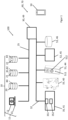
- the door arrangement 100 comprises a computing unit 10.
- the computing unit 10 comprises a computing device 11, which is designed as a personal computer.
- the computing device comprises a screen 12 and a keyboard 13.
- the computing unit 10 comprises at least one electronic memory.
- this can be a cloud memory.
- a first database 20, a second database 21, and a third database 22 are stored in the memory.
- the first and second databases 20, 21 can be configured as a common database.
- the second and third databases 21, 22 can be configured as a common database.
- the first and third databases 20, 22 can be configured as a common database.
- the first to third databases 20, 21, 22 are integrated into a common database.
- the door systems 60, 61, 62 are each part of the door arrangement 100.
- the door systems 60, 61, 62 each comprise a control unit 30 as a first door component.
- the door systems 60, 61, 62 each comprise a first bus system 32, e.g., a CAN bus.
- the door systems 60, 61, 62 each comprise at least one door drive 35, 36, for example, a sliding door or swing door drive.
- the door drive 35, 36 and the control unit 30 are connected to the first bus system 32.
- the presence of the control unit 30 makes it possible to make complex functional sequences and/or complex decisions.
- the door drives 35, 36 each comprise a schematically illustrated drive controller 351, 361 and a schematically illustrated motor 352, 362.
- the drive controller 351, 361 is connected to the first bus system 32.
- the drive controller 351, 361 serves to control the motor 352, 362 of the respective door drive 35, 36 using a four-quadrant control system.
- the drive controller 351, 361 comprises at least one processor and at least one electronic memory.
- the control unit 30 also includes at least one processor and at least one electronic memory.
- the processor of the control unit 30 has greater computing power than the drive controller 351, 361 and serves to control processes of the door system 60, 61, 62.
- At least the control unit 30 includes a timer.
- control unit 30 serves to establish the information technology connection to the computing unit 10.
- control unit 30 and the computing unit are connected to a second bus system 25, e.g., Ethernet.
- the control unit can receive an electronic configuration via the second bus system 25.
- the control unit 30 can send operating data to the computing unit 10.
- the operating data is stored in the third database 22.
- the control unit 30 and the drive controller 351 of the door system 60 or one of the drive controllers 351, 361 of the door systems 61, 62 are preferably arranged in a housing. Particularly preferably, the motor 352, 362 is also arranged in the housing.
- the door systems 60, 61, 62 include additional door components.
- the first door system 60 in Figure 1 includes, for example, a motor lock 33, an escape route control 51 with an emergency button 512, an electromagnetic door lock 52, and a hazard detector, in particular a smoke detector 53, as additional door components.
- the door components 35, 33, 51, 52, 53 have different functions and functional properties.
- the door components 33, 51, 52, 53 belong to different door component types 40, 44, 45, 46, just as the control unit 30 and the motor drive 35 each belong to different door component types 49, 41.
- the second door system 61 in Figure 2 and the third door system 62 in Figure 3 Each comprises several motorized door drives 35, 36 as door components.
- the motorized door drives 35, 36 are identically designed and thus belong to the same door component type 41.
- the second door system 61 and the third door system 62 comprise several sensors 37, 38 and 56, 57 as door components.
- the sensors 37, 38 and 56, 57 serve to detect the approach of a person to the door leaves.
- the motorized door drives 35, 36 can then open the door leaves in a predetermined time sequence as a functional sequence.
- safety sensors (not shown) can serve to stop the door by means of the door drive 35, 36 to prevent injury to the person.
- the sensors 37, 38 and 56, 57 are identically designed and thus belong to the same door component type 42.
- a program switch 39 or 58 is provided as a door component. Using the program switch 39, 58, a user can determine whether the sensors 37, 38 or 56, 57 trigger a motorized door opening upon detecting a person. Thus, the program switch can be used to set various operating modes, namely at least automatic mode and manual mode.
- the program switch 39 is assigned to a dedicated door component type 43.
- the door drives 35, 36 of the second door system 61 are each designed to be arranged on a door leaf of a double-leaf door.
- the second door system 61 comprises a motor lock 33 for a moving leaf of the double-leaf door and a motor lock 34 for a passive leaf of the double-leaf door.
- the motor locks 33, 34 are each assigned to their own door component types 40, 47.
- a further door component of the second door system 61 is designed as a reader 31 as a further door component type 48.
- the reader 31 can, in particular, communicate wirelessly with a card or a mobile phone to receive an access attribute. An access decision is made by the control unit 30.
- the door drives 35, 36 of the third door system 62 are each designed to be arranged on a door leaf of a lock, each with a single-leaf door.
- the third door system 62 comprises two motor locks 33, 59, each for a moving leaf.
- the motor locks each belong to the same door component type 40.
- the door system 62 also comprises several readers 29, 31, each of which is provided for arrangement on a door of the lock.
- the door components 30, 33, 35, 36, 56, 57, 58 of the third embodiment 62 are connected to the first bus system 32.
- the components 29, 30, 31 are connected via the third bus system 55.
- the control unit 30 comprises a transmitting and receiving unit for wireless short-range communication with a mobile terminal 50.
- the door arrangement according to the invention comprises the mobile terminal 50.
- the door systems 60, 61, 62 correspond to different door system types 70, 71, 72.
- a door system 60, 61, 62 is characterized in that each door system 60, 61, 62 comprises a common electronic configuration.
- the configuration 82 is embodied as at least one electronic file and can be stored on the control unit 30.
- Preferably, exactly one configuration is provided for each door system type 70, 71, 72.
- a door system 60, 61, 62 each comprises a common control unit 30.
- the control unit serves to connect to the computing unit 10.
- a door system 60, 61, 62 can be provided for installation on one or more doors, depending on the door system type 70, 71, 72.
- a door system is used, for example, for installation on two double-leaf doors arranged one behind the other or a hotel corridor with, for example, four room doors.
- a door arrangement 100 may comprise multiple door systems 60, 61, 62.
- the door systems 60, 61, 62 may belong to the same or different door system types 70, 71, 72.
- the door systems 60, 61, 62 are preferably connected to one another and/or to the computing unit 10 via the second bus system 25.
- the door systems 60, 61, 62 each comprise signal-emitting door components, i.e. a signal generator.
- the database also stores whether the door should be opened with one or two leaves for individual access attributes or individual access attribute groups.
- an opening mode can be assigned to access attributes or access attribute groups in the database.
- the access attribute group "Nurse” can be assigned a double-leaf door opening
- the access attribute group "Doctor” a single-leaf door opening. If the control unit 30 determines that a user of the access attribute group who has a single-leaf door opening, seeks access, the control unit 30 will control the door drive 35 to open the door, but not the door drive 36.
- the type of use of the access attribute or the element comprising the access attribute determines a parameter or the opening mode.
- a long presentation of the mobile terminal 50 comprising the access attribute to the reader 31 can lead to a longer hold-open time than a short presentation of the terminal 50 to the reader 31.
- a long presentation can additionally or alternatively, for example, lead to a double-leaf opening, while a short presentation leads to a single-leaf opening.
- control unit 30 does not include the database, but the assignment of the parameters or opening modes to access attributes or access attribute groups takes place in the computing unit 10, preferably in the third database 22.
- the control unit 30 can query the computing unit 10 when making the access decision.
- the parameter or opening mode is part of the access attribute.
- the parameter or opening mode is transmitted wirelessly from the mobile device 50 to the reader 31 during the access authorization request.
- the reader 31 sends the parameter or opening mode to the control unit 30 via the third bus system 55.
- the signal transmitters are the sensors 56, 57 and the readers 29, 31.
- the sensors 56, 57 are evaluated by the control unit 30.
- the control unit 30 controls the drive control 351, 361 so that the door is opened by motor.
- control processes related to the specific properties of a motor, e.g., a specific sliding door motor, are handled by the drive control 351, 361.
- Higher-level control processes e.g., when which locking element 33, 34, 59 or which door drive 35, 36 is to be controlled, are preferably and/or predominantly handled by the control unit 30. This allows the door drive 35, 36 to be replaced without the need for significant modifications to the remaining door system 60, 61, 62. In particular, no modified cabling is necessary.
Landscapes
- Power-Operated Mechanisms For Wings (AREA)
Claims (16)
- Système de porte (60, 61, 62) pour une ou plusieurs portes,dans lequel le système de porte (60, 61, 62) comprend au moins un entraînement de porte motorisé (35, 36),dans lequel l'entraînement de porte est un entraînement de porte coulissante, un entraînement de porte battante ou un entraînement de porte tournante, dans lequel l'entraînement de porte (35, 36) comprend un moteur (352, 362) et une commande d'entraînement (351, 361) pour commander le moteur (352, 362) de l'entraînement de porte (35, 36), dans lequel le système de porte (60, 61, 62) comprend un appareil de commande (30) qui est relié à la commande d'entraînement (351, 361),caractérisé en ce quel'appareil de commande (30) est conçu pour évaluer, sur la base de signaux reçus, si la porte doit être ouverte au moyen du moteur (352, 362), dans lequel l'appareil de commande (30) amène la commande d'entraînement (351, 361) à commander le moteur (352, 362) sur la base de l'évaluation,dans lequel le système de porte (60, 61, 62) comprend au moins un élément de verrouillage (33, 34, 52, 59), dans lequel une séquence est prédéfinie par un micrologiciel de l'appareil de commande (30), dans lequel la séquence comprend une étape de fonctionnement à exécuter par le moteur (352, 362) et une étape de fonctionnement à exécuter par l'élément de verrouillage (33, 34, 52, 59).
- Système de porte (60, 61, 62) selon la revendication 1, dans lequel la commande d'entraînement (351, 361) et l'appareil de commande (30) sont reliés entre eux par un premier système de bus (32), en particulier dans lequel l'appareil de commande (30) peut être relié à un second système de bus (25), en particulier compatible IP, dans lequel l'appareil de commande (30) est conçu pour recevoir une configuration électronique (82) pour commander le système de porte (60, 61, 62) par l'intermédiaire du second système de bus (25) et/ou pour envoyer un état de fonctionnement du système de porte (60, 61, 62) par l'intermédiaire du second système de bus (25).
- Système de porte (60, 61, 62) selon la revendication 1 ou 2, dans lequel la commande d'entraînement (351, 361) est conçue pour accélérer et/ou freiner le moteur (352, 362) de sorte qu'une porte est ouverte, arrêtée et/ou fermée.
- Système de porte (60, 61, 62) selon l'une quelconque des revendications précédentes, dans lequel l'appareil de commande (30) comprend au moins un processeur et la commande d'entraînement (351, 361) comprend au moins un processeur, dans lequel l'appareil de commande (30) comprend la puissance de calcul supérieure à celle de la commande d'entraînement (351, 361), en particulier dans lequel l'appareil de commande (30) comprend un accélérateur matériel, de préférence un accélérateur pour l'utilisation de l'intelligence artificielle, de manière particulièrement préférée une unité de traitement de vision.
- Système de porte (60, 61, 62) selon l'une quelconque des revendications précédentes, dans lequel le système de porte (60, 61, 62) comprend au moins un capteur (37, 38, 56, 57), dans lequel un signal du capteur (37, 38, 56, 57) est destiné à provoquer une ouverture, un arrêt et/ou une fermeture de la porte au moyen de l'entraînement de porte (35, 36), dans lequel le capteur (56, 57) est relié au premier système de bus (32) et/ou dans lequel le système de porte (60, 61, 62) est conçu pour évaluer les signaux du capteur (56, 57) par l'appareil de commande (30), dans lequel l'appareil de commande (30) amène la commande d'entraînement (351, 361) à commander le moteur (352, 362) sur la base de l'évaluation.
- Système de porte (60, 61, 62) selon l'une quelconque des revendications précédentes, dans lequel au moins un paramètre pour la commande du moteur (352, 362) est enregistré dans l'appareil de commande (30) et/ou peut être reçu par l'appareil de commande (30), dans lequel l'appareil de commande (30) amène la commande d'entraînement (351, 361) à commander le moteur (352, 362) en conséquence, dans lequel en particulier les paramètres servent à régler au moins une, de préférence plusieurs, des caractéristiques suivantes du système de porte (60, 61, 62) :• une vitesse d'ouverture de la porte,• une vitesse de fermeture de la porte,• un temps de maintien en position ouverte de la porte,• une puissance moteur du moteur (352, 362)• une largeur d'ouverture ou un angle d'ouverture de la porte• une commande du moteur (352, 362) en fonction d'une action de l'utilisateur, en particulier en fonction d'un actionnement d'une poignée de porte pour ouvrir la porte.
- Système de porte (60, 61, 62) selon l'une quelconque des revendications précédentes, dans lequel au moins un paramètre pour la commande du moteur (352, 362) est enregistré individuellement pour des utilisateurs autorisés ou pour des groupes d'utilisateurs autorisés ou individuellement pour des attributs d'accès ou pour des groupes d'attributs d'accès dans le système de porte (60, 61, 62), en particulier dans l'appareil de commande (30), et/ou peut être reçu par le système de porte (60, 61, 62), en particulier par l'appareil de commande (30), en particulier comme partie d'un attribut d'accès, et/ou dans lequel le paramètre dépend de l'utilisation de l'attribut d'accès.
- Système de porte (60, 61, 62) selon l'une quelconque des revendications précédentes, dans lequel le appareil de commande (30) comprend une mémoire, dans lequel le micrologiciel est mémorisé dans la mémoire, dans lequel le micrologiciel sert à exécuter au moins une séquence de plusieurs étapes de fonctionnement devant être exécutées par le système de porte (60, 61, 62), dans lequel le micrologiciel est indépendant de la réalisation du moteur (352, 362) de l'entraînement de porte (35, 36).
- Système de porte (60, 61, 62) selon l'une quelconque des revendications précédentes, dans lequel il est prédéfini dans le système de porte (60, 61, 62), en particulier dans le micrologiciel de l'appareil de commande (30), dans quelles conditions environnementales et de quelle manière le moteur (352, 362) doit être commandé, en particulier dans lequel il est prédéfini en cas de danger si la porte doit être ouverte ou fermée par le moteur (352, 362).
- Système de porte (60, 61, 62) selon l'une quelconque des revendications précédentes, dans lequel le système de porte (60, 61, 62) comprend un appareil de commande (30) et plusieurs entraînements de porte (35, 36), dans lequel les entraînements de porte (35, 36) comprennent respectivement une commande d'entraînement (351, 361), dans lequel l'appareil de commande (30) est conçu pour coordonner les commandes d'entraînement (351, 361) en une séquence, en particulier dans lequel les entraînements de porte (351, 361) sont conçus pour être disposés respectivement sur un vantail de porte d'une porte à deux vantaux et/ou sur des vantaux de porte agencés les uns derrière les autres.
- Système de porte (60, 61, 62) selon la revendication 10, dans lequel les commandes d'entraînement (351, 361) sont reliées au même premier système de bus (32) et/ou la séquence est enregistrée dans le micrologiciel de l'appareil de commande (30).
- Système de porte (60, 61, 62) selon l'une quelconque des revendications précédentes, dans lequel l'élément de verrouillage (33, 34, 52, 59) est relié au premier système de bus (32).
- Système de porte (60, 61, 62) selon l'une quelconque des revendications précédentes, dans lequel le système de porte (60, 61, 62) comprend un dispositif d'authentification (30), dans lequel le dispositif d'authentification (30) étant conçu pour recevoir un attribut d'accès pour l'authentification, dans lequel le système de porte (60, 61, 62) est conçu, sur la base de l'attribut d'accès et/ou de la manière d'utiliser l'attribut d'accès• pour changer un mode de fonctionnement de l'entraînement de porte (35, 36), en particulier d'un mode automatique, dans lequel, lors de l'approche de la porte, détectée par un capteur, d'une personne, l'entraînement de porte (35, 36) ouvre la porte par un moteur, à un mode manuel, dans lequel, lors d'une approche de la porte, détectée par un capteur, d'une personne, l'entraînement de porte (35, 36) omet d'ouvrir la porte par un moteur, ou inversement,• pour commander un entraînement de porte (35, 36) pour ouvrir un vantail de porte ou plusieurs entraînements de porte (35, 36) pour ouvrir plusieurs vantaux de porte,• pour respecter ou annuler une séquence temporelle pour commander un moteur (362) d'un second entraînement de porte (36) après la commande d'un moteur (352) d'un premier entraînement de porte (35) selon une condition enregistrée dans le système de porte (60, 61, 62).
- Système de porte (60, 61, 62) selon l'une quelconque des revendications précédentes, dans lequel le système de porte (60, 61, 62) comprend une serrure à moteur (33, 34, 59), dans lequel la commande d'entraînement (351, 361) commande la serrure à moteur (33, 34, 59), en particulier dans lequel la serrure à moteur (33, 34, 59) est reliée au premier système de bus (32).
- Système de porte (60, 61, 62) selon l'une quelconque des revendications précédentes, dans lequel il est enregistré dans le micrologiciel quels composants de porte (33, 34, 35, 36, 51, 52, 53, 56, 57, 58, 59) du système de porte (60, 61, 62), qui sont reliés au premier système de bus (32), sont nécessaires pour la séquence, dans lequel le système de porte (60, 61, 62), en particulier l'appareil de commande (30), vérifie si les composants de porte (33, 34, 35, 36, 51, 52, 53, 56, 57, 58, 59) sont reliés au premier système de bus (32), dans lequel le système de porte (60, 61, 62) refuse d'exécuter la séquence en cas d'issue négative de la vérification.
- Système de porte (60, 61, 62) selon l'une quelconque des revendications précédentes, dans lequel la commande d'entraînement (351, 352) et l'appareil de commande (30) sont agencés dans un boîtier, dans lequel le boîtier loge en particulier un moteur (352, 362) de l'entraînement de porte (35, 36).
Priority Applications (5)
| Application Number | Priority Date | Filing Date | Title |
|---|---|---|---|
| EP21159073.2A EP4050188B1 (fr) | 2021-02-24 | 2021-02-24 | Système de porte pour au moins une porte |
| PL21159073.2T PL4050188T3 (pl) | 2021-02-24 | 2021-02-24 | System drzwi dla jednych albo więcej drzwi |
| ES21159073T ES3032777T3 (en) | 2021-02-24 | 2021-02-24 | Door system for one or more doors |
| US18/547,288 US20240125166A1 (en) | 2021-02-24 | 2022-02-23 | Door system for one or more doors |
| PCT/EP2022/054533 WO2022180099A1 (fr) | 2021-02-24 | 2022-02-23 | Système de porte destiné à au moins une porte |
Applications Claiming Priority (1)
| Application Number | Priority Date | Filing Date | Title |
|---|---|---|---|
| EP21159073.2A EP4050188B1 (fr) | 2021-02-24 | 2021-02-24 | Système de porte pour au moins une porte |
Publications (3)
| Publication Number | Publication Date |
|---|---|
| EP4050188A1 EP4050188A1 (fr) | 2022-08-31 |
| EP4050188C0 EP4050188C0 (fr) | 2025-04-02 |
| EP4050188B1 true EP4050188B1 (fr) | 2025-04-02 |
Family
ID=74758517
Family Applications (1)
| Application Number | Title | Priority Date | Filing Date |
|---|---|---|---|
| EP21159073.2A Active EP4050188B1 (fr) | 2021-02-24 | 2021-02-24 | Système de porte pour au moins une porte |
Country Status (3)
| Country | Link |
|---|---|
| EP (1) | EP4050188B1 (fr) |
| ES (1) | ES3032777T3 (fr) |
| PL (1) | PL4050188T3 (fr) |
Families Citing this family (1)
| Publication number | Priority date | Publication date | Assignee | Title |
|---|---|---|---|---|
| GB2574021B (en) | 2018-05-22 | 2023-03-01 | Trp Sealing Systems Ltd | Gasket for a plate heat exchanger |
Citations (9)
| Publication number | Priority date | Publication date | Assignee | Title |
|---|---|---|---|---|
| DE3940176C1 (fr) | 1989-12-05 | 1991-05-16 | Gallenschuetz Metallbau Gmbh, 7580 Buehl, De | |
| DE19531323A1 (de) | 1994-10-15 | 1996-04-18 | Geze Gmbh & Co | Ein Diagnose- und/oder Überwachungsverfahren und eine Sicherheitseinrichtung zur Durchführung des Verfahrens für mindestens eine Tür, vorzugsweise in Flucht- und Rettungswegen |
| EP0799962A1 (fr) | 1996-04-02 | 1997-10-08 | Heinrich Landert | Méthode d'opération d'un dispositif de porte et dispositif de porte fonctionnant selon ce procédé |
| DE19929193A1 (de) | 1999-06-27 | 2000-12-28 | Geze Gmbh | Flucht- und Rettungswegeinrichtung für mindestens eine Tür oder ein Fenster in Flucht- und Rettungswegen |
| US6177771B1 (en) | 1999-11-24 | 2001-01-23 | Brookfield Industries, Inc. | Automatic door operator |
| US20020092237A1 (en) | 1999-07-28 | 2002-07-18 | Hebda Thomas J. | Device for controlling a door operator |
| DE102009004503B4 (de) | 2009-01-09 | 2017-11-16 | Dormakaba Deutschland Gmbh | Verfahren zum Betrieb eines Drehflügelbetätigers und damit betriebene Drehflügelbetätiger |
| EP3267451A1 (fr) * | 2016-07-04 | 2018-01-10 | dormakaba Deutschland GmbH | Système de sécurité |
| EP3348767A1 (fr) | 2017-01-12 | 2018-07-18 | dormakaba Deutschland GmbH | Système permettant d'obtenir au moins un paramètre d'entraînement d'un système de porte |
Family Cites Families (2)
| Publication number | Priority date | Publication date | Assignee | Title |
|---|---|---|---|---|
| US20030033388A1 (en) * | 2001-08-09 | 2003-02-13 | Hom Wayne C. | Method and apparatus for controlling a plurality of security gate operating mechanisms |
| US20190281120A1 (en) * | 2018-03-09 | 2019-09-12 | Martin H. Weik, III | Method for designing data and operation management system for the manufacturing, operation and maintenance of ip door controllers |
-
2021
- 2021-02-24 PL PL21159073.2T patent/PL4050188T3/pl unknown
- 2021-02-24 ES ES21159073T patent/ES3032777T3/es active Active
- 2021-02-24 EP EP21159073.2A patent/EP4050188B1/fr active Active
Patent Citations (10)
| Publication number | Priority date | Publication date | Assignee | Title |
|---|---|---|---|---|
| DE3940176C1 (fr) | 1989-12-05 | 1991-05-16 | Gallenschuetz Metallbau Gmbh, 7580 Buehl, De | |
| DE19531323A1 (de) | 1994-10-15 | 1996-04-18 | Geze Gmbh & Co | Ein Diagnose- und/oder Überwachungsverfahren und eine Sicherheitseinrichtung zur Durchführung des Verfahrens für mindestens eine Tür, vorzugsweise in Flucht- und Rettungswegen |
| EP0799962A1 (fr) | 1996-04-02 | 1997-10-08 | Heinrich Landert | Méthode d'opération d'un dispositif de porte et dispositif de porte fonctionnant selon ce procédé |
| US6084367A (en) | 1996-04-02 | 2000-07-04 | Landert; Heinrich | Method of operating a door system and a door system operating by this method |
| DE19929193A1 (de) | 1999-06-27 | 2000-12-28 | Geze Gmbh | Flucht- und Rettungswegeinrichtung für mindestens eine Tür oder ein Fenster in Flucht- und Rettungswegen |
| US20020092237A1 (en) | 1999-07-28 | 2002-07-18 | Hebda Thomas J. | Device for controlling a door operator |
| US6177771B1 (en) | 1999-11-24 | 2001-01-23 | Brookfield Industries, Inc. | Automatic door operator |
| DE102009004503B4 (de) | 2009-01-09 | 2017-11-16 | Dormakaba Deutschland Gmbh | Verfahren zum Betrieb eines Drehflügelbetätigers und damit betriebene Drehflügelbetätiger |
| EP3267451A1 (fr) * | 2016-07-04 | 2018-01-10 | dormakaba Deutschland GmbH | Système de sécurité |
| EP3348767A1 (fr) | 2017-01-12 | 2018-07-18 | dormakaba Deutschland GmbH | Système permettant d'obtenir au moins un paramètre d'entraînement d'un système de porte |
Non-Patent Citations (9)
| Title |
|---|
| ANONYMOUS: "Building Automation", INDUSTRY BROCHURE, DUNKERMOTOREN GMBH, 1 December 2019 (2019-12-01), pages 1 - 2, XP093358719, Retrieved from the Internet <URL:https://web.archive.org/web/20201026091950/https://www.dunkermotoren.com/en/downloads/industry-brochures/> |
| ANONYMOUS: "Data Sheet Motion Controllers V2.5, 4-Quadrant PWM with RS232 or CAN interface", DATA SHEET, FAULHABER, 18 February 2020 (2020-02-18), pages 1 - 2, XP093358813, Retrieved from the Internet <URL:https://www.faulhaber.com/fileadmin/Import/Media/EN_MCDC3003P_V2-5_DFF.pdf> |
| ANONYMOUS: "MOTORS GEARBOXES CONTROLLERS 2016/17 EN/DE", CATALOGUE DUNKERMOTOREN, DONKERMOTOREN GMBH, 1 January 2016 (2016-01-01), pages 1 - 228, XP093358732, Retrieved from the Internet <URL:https://www.scribd.com/document/346590997/Dunkermotoren-Complete-2017-Catalog> |
| ANONYMOUS: "Product range/ Lieferübersicht MOTORS GEARBOXES CONTROLLERS 2017 EN/DE", PRODUCT RANGE/ LIEFERÜBERSICHT MOTORS GEARBOXES CONTROLLERS, DUNKERMOTOREN GMBH, 1 May 2017 (2017-05-01), pages 1 - 20, XP093358734, Retrieved from the Internet <URL:https://www.servo2go.com/media/wysiwyg/pdfs/catalogs-white-papers/dunkermotoren/dunkermotoren-product-range-catalog.pdf> |
| ANONYMOUS: "Technische Informationen (DFF_TI_03-2020_DE)", FAULHABER TECHNISCHE INFORMATIONEN, FAULHABER, DE, 1 March 2020 (2020-03-01), DE, pages 1 - 158, XP093358809, Retrieved from the Internet <URL:https://web.archive.org/web/20200422070436/https://www.faulhaber.com/fileadmin/Import/Media/DE_TECHNICAL_INFORMATION.pdf> |
| ANONYMOUS: "Türautomation mit dem Weltmarktführer", DUNKERMOTOREN - BRANCHEN - GEBÄUDEAUTOMATISIERUNG, DUNKERMOTOREN GMBH, 27 January 2026 (2026-01-27), pages 1 - 2, XP093358741, Retrieved from the Internet <URL:https://www.dunkermotoren.de/de-de/industries/building-automation> |
| D4a - Benutzerhandbuch Slimdrive EMD, EMD-F u.a., Mat.-Nr. 114075 |
| D4b - Slimdrive EMD Slimdrive EMD-F DE Montage- und Serviceanleitung |
| D4c - Diverse Lieferscheine und Rechnungen aus den Jahren 2011 bis 2018 |
Also Published As
| Publication number | Publication date |
|---|---|
| EP4050188C0 (fr) | 2025-04-02 |
| EP4050188A1 (fr) | 2022-08-31 |
| ES3032777T3 (en) | 2025-07-24 |
| PL4050188T3 (pl) | 2025-08-18 |
Similar Documents
| Publication | Publication Date | Title |
|---|---|---|
| EP3542350B1 (fr) | Système de contrôle d'accès comprenant une actualisation d'état automatique | |
| EP3007139B1 (fr) | Systeme de fermeture de porte | |
| DE102009010491A1 (de) | Zugangssteuerungseinrichtung | |
| WO2022179716A1 (fr) | Procédé de démarrage d'un système de porte | |
| EP1321901B1 (fr) | Méthode pour contrôler les droits d'accès à un objet | |
| DE19815768C2 (de) | Kippfensterverriegelung einer Objektsicherungsanlage | |
| WO2022180097A1 (fr) | Système de porte destiné à une ou plusieurs portes et contenant de multiples composants de porte ainsi qu'un premier bus de communication | |
| EP3096299B1 (fr) | Installation de fermeture et procédé de fonctionnement d'une installation de fermeture pour une porte de batiment | |
| EP2350981B1 (fr) | Système de contrôle et de commande d' accès | |
| EP0949597B1 (fr) | Verrou mécanique pour fenêtre ou porte d'une installation pour la securité d'objets fonctionnant sans fil | |
| EP4050188A1 (fr) | Système de porte pour au moins une porte | |
| DE19929193A1 (de) | Flucht- und Rettungswegeinrichtung für mindestens eine Tür oder ein Fenster in Flucht- und Rettungswegen | |
| EP3096297A1 (fr) | Installation de fermeture pour une porte de batiment | |
| EP0474975B1 (fr) | Dispositif de contrôle d'accès | |
| EP3027827B1 (fr) | Poignée de fenêtre, verrouillable de façon électromagnétique | |
| WO2022180099A1 (fr) | Système de porte destiné à au moins une porte | |
| EP1338735B1 (fr) | Système, installation et procédé de contrôle d'accès | |
| EP3362997A1 (fr) | Contenant verrouillable | |
| EP4050578A1 (fr) | Système de porte pour au moins une porte pourvue de plusieurs parties de porte, ainsi que d'un premier bus de communication | |
| WO2022180088A1 (fr) | Procédé d'installation d'une pluralité de composants de porte | |
| EP4298621A1 (fr) | Procédé de démarrage d'un système de porte | |
| DE19815767A1 (de) | Objektsicherungsanlage | |
| WO2022180090A1 (fr) | Système de porte doté d'un entraînement de porte et système de sécurisation d'une voie d'évacuation, reliés entre eux par l'intermédiaire d'une liaison de communication afin d'effectuer un processus de commande coordonné | |
| DE102004056987A1 (de) | Schließvorrichtung und Schließanlage, umfassend wenigstens eine Schließvorrichtung | |
| EP4050576A1 (fr) | Procédé de mise en service d'un système de porte |
Legal Events
| Date | Code | Title | Description |
|---|---|---|---|
| PUAI | Public reference made under article 153(3) epc to a published international application that has entered the european phase |
Free format text: ORIGINAL CODE: 0009012 |
|
| STAA | Information on the status of an ep patent application or granted ep patent |
Free format text: STATUS: THE APPLICATION HAS BEEN PUBLISHED |
|
| AK | Designated contracting states |
Kind code of ref document: A1 Designated state(s): AL AT BE BG CH CY CZ DE DK EE ES FI FR GB GR HR HU IE IS IT LI LT LU LV MC MK MT NL NO PL PT RO RS SE SI SK SM TR |
|
| STAA | Information on the status of an ep patent application or granted ep patent |
Free format text: STATUS: REQUEST FOR EXAMINATION WAS MADE |
|
| 17P | Request for examination filed |
Effective date: 20230224 |
|
| RBV | Designated contracting states (corrected) |
Designated state(s): AL AT BE BG CH CY CZ DE DK EE ES FI FR GB GR HR HU IE IS IT LI LT LU LV MC MK MT NL NO PL PT RO RS SE SI SK SM TR |
|
| STAA | Information on the status of an ep patent application or granted ep patent |
Free format text: STATUS: EXAMINATION IS IN PROGRESS |
|
| 17Q | First examination report despatched |
Effective date: 20240311 |
|
| GRAP | Despatch of communication of intention to grant a patent |
Free format text: ORIGINAL CODE: EPIDOSNIGR1 |
|
| STAA | Information on the status of an ep patent application or granted ep patent |
Free format text: STATUS: GRANT OF PATENT IS INTENDED |
|
| INTG | Intention to grant announced |
Effective date: 20250107 |
|
| GRAS | Grant fee paid |
Free format text: ORIGINAL CODE: EPIDOSNIGR3 |
|
| GRAA | (expected) grant |
Free format text: ORIGINAL CODE: 0009210 |
|
| STAA | Information on the status of an ep patent application or granted ep patent |
Free format text: STATUS: THE PATENT HAS BEEN GRANTED |
|
| AK | Designated contracting states |
Kind code of ref document: B1 Designated state(s): AL AT BE BG CH CY CZ DE DK EE ES FI FR GB GR HR HU IE IS IT LI LT LU LV MC MK MT NL NO PL PT RO RS SE SI SK SM TR |
|
| REG | Reference to a national code |
Ref country code: GB Ref legal event code: FG4D Free format text: NOT ENGLISH |
|
| REG | Reference to a national code |
Ref country code: CH Ref legal event code: EP |
|
| REG | Reference to a national code |
Ref country code: DE Ref legal event code: R096 Ref document number: 502021007066 Country of ref document: DE |
|
| REG | Reference to a national code |
Ref country code: IE Ref legal event code: FG4D Free format text: LANGUAGE OF EP DOCUMENT: GERMAN |
|
| U01 | Request for unitary effect filed |
Effective date: 20250429 |
|
| U07 | Unitary effect registered |
Designated state(s): AT BE BG DE DK EE FI FR IT LT LU LV MT NL PT RO SE SI Effective date: 20250507 |
|
| REG | Reference to a national code |
Ref country code: ES Ref legal event code: FG2A Ref document number: 3032777 Country of ref document: ES Kind code of ref document: T3 Effective date: 20250724 |
|
| PG25 | Lapsed in a contracting state [announced via postgrant information from national office to epo] |
Ref country code: GR Free format text: LAPSE BECAUSE OF FAILURE TO SUBMIT A TRANSLATION OF THE DESCRIPTION OR TO PAY THE FEE WITHIN THE PRESCRIBED TIME-LIMIT Effective date: 20250703 |
|
| PG25 | Lapsed in a contracting state [announced via postgrant information from national office to epo] |
Ref country code: HR Free format text: LAPSE BECAUSE OF FAILURE TO SUBMIT A TRANSLATION OF THE DESCRIPTION OR TO PAY THE FEE WITHIN THE PRESCRIBED TIME-LIMIT Effective date: 20250402 |
|
| PG25 | Lapsed in a contracting state [announced via postgrant information from national office to epo] |
Ref country code: RS Free format text: LAPSE BECAUSE OF FAILURE TO SUBMIT A TRANSLATION OF THE DESCRIPTION OR TO PAY THE FEE WITHIN THE PRESCRIBED TIME-LIMIT Effective date: 20250702 |
|
| PG25 | Lapsed in a contracting state [announced via postgrant information from national office to epo] |
Ref country code: IS Free format text: LAPSE BECAUSE OF FAILURE TO SUBMIT A TRANSLATION OF THE DESCRIPTION OR TO PAY THE FEE WITHIN THE PRESCRIBED TIME-LIMIT Effective date: 20250802 |
|
| PLBI | Opposition filed |
Free format text: ORIGINAL CODE: 0009260 |
|
| PG25 | Lapsed in a contracting state [announced via postgrant information from national office to epo] |
Ref country code: SM Free format text: LAPSE BECAUSE OF FAILURE TO SUBMIT A TRANSLATION OF THE DESCRIPTION OR TO PAY THE FEE WITHIN THE PRESCRIBED TIME-LIMIT Effective date: 20250402 |
|
| REG | Reference to a national code |
Ref country code: CH Ref legal event code: L10 Free format text: ST27 STATUS EVENT CODE: U-0-0-L10-L00 (AS PROVIDED BY THE NATIONAL OFFICE) Effective date: 20260114 |
|
| PLAX | Notice of opposition and request to file observation + time limit sent |
Free format text: ORIGINAL CODE: EPIDOSNOBS2 |
|
| PG25 | Lapsed in a contracting state [announced via postgrant information from national office to epo] |
Ref country code: SK Free format text: LAPSE BECAUSE OF FAILURE TO SUBMIT A TRANSLATION OF THE DESCRIPTION OR TO PAY THE FEE WITHIN THE PRESCRIBED TIME-LIMIT Effective date: 20250402 |
|
| 26 | Opposition filed |
Opponent name: GEZE GMBH Effective date: 20260102 |
|
| REG | Reference to a national code |
Ref country code: CH Ref legal event code: U11 Free format text: ST27 STATUS EVENT CODE: U-0-0-U10-U11 (AS PROVIDED BY THE NATIONAL OFFICE) Effective date: 20260301 |
|
| U20 | Renewal fee for the european patent with unitary effect paid |
Year of fee payment: 6 Effective date: 20260225 |
|
| PGFP | Annual fee paid to national office [announced via postgrant information from national office to epo] |
Ref country code: GB Payment date: 20260220 Year of fee payment: 6 |
|
| PGFP | Annual fee paid to national office [announced via postgrant information from national office to epo] |
Ref country code: NO Payment date: 20260220 Year of fee payment: 6 Ref country code: IE Payment date: 20260218 Year of fee payment: 6 |
|
| PGFP | Annual fee paid to national office [announced via postgrant information from national office to epo] |
Ref country code: CZ Payment date: 20260217 Year of fee payment: 6 Ref country code: CH Payment date: 20260301 Year of fee payment: 6 |
|
| PGFP | Annual fee paid to national office [announced via postgrant information from national office to epo] |
Ref country code: PL Payment date: 20260213 Year of fee payment: 6 |
|
| PLBB | Reply of patent proprietor to notice(s) of opposition received |
Free format text: ORIGINAL CODE: EPIDOSNOBS3 |