EP4052841A1 - Spannvorrichtung - Google Patents
Spannvorrichtung Download PDFInfo
- Publication number
- EP4052841A1 EP4052841A1 EP20882444.1A EP20882444A EP4052841A1 EP 4052841 A1 EP4052841 A1 EP 4052841A1 EP 20882444 A EP20882444 A EP 20882444A EP 4052841 A1 EP4052841 A1 EP 4052841A1
- Authority
- EP
- European Patent Office
- Prior art keywords
- pressure fluid
- discharge port
- fluid supply
- valve
- valve case
- Prior art date
- Legal status (The legal status is an assumption and is not a legal conclusion. Google has not performed a legal analysis and makes no representation as to the accuracy of the status listed.)
- Pending
Links
Images




Classifications
-
- B—PERFORMING OPERATIONS; TRANSPORTING
- B25—HAND TOOLS; PORTABLE POWER-DRIVEN TOOLS; MANIPULATORS
- B25J—MANIPULATORS; CHAMBERS PROVIDED WITH MANIPULATION DEVICES
- B25J15/00—Gripping heads and other end effectors
- B25J15/04—Gripping heads and other end effectors with provision for the remote detachment or exchange of the head or parts thereof
-
- B—PERFORMING OPERATIONS; TRANSPORTING
- B25—HAND TOOLS; PORTABLE POWER-DRIVEN TOOLS; MANIPULATORS
- B25J—MANIPULATORS; CHAMBERS PROVIDED WITH MANIPULATION DEVICES
- B25J15/00—Gripping heads and other end effectors
- B25J15/04—Gripping heads and other end effectors with provision for the remote detachment or exchange of the head or parts thereof
- B25J15/0408—Connections means
- B25J15/0416—Connections means having balls
-
- B—PERFORMING OPERATIONS; TRANSPORTING
- B23—MACHINE TOOLS; METAL-WORKING NOT OTHERWISE PROVIDED FOR
- B23Q—DETAILS, COMPONENTS, OR ACCESSORIES FOR MACHINE TOOLS, e.g. ARRANGEMENTS FOR COPYING OR CONTROLLING; MACHINE TOOLS IN GENERAL CHARACTERISED BY THE CONSTRUCTION OF PARTICULAR DETAILS OR COMPONENTS; COMBINATIONS OR ASSOCIATIONS OF METAL-WORKING MACHINES, NOT DIRECTED TO A PARTICULAR RESULT
- B23Q3/00—Devices holding, supporting, or positioning work or tools, of a kind normally removable from the machine
- B23Q3/02—Devices holding, supporting, or positioning work or tools, of a kind normally removable from the machine for mounting on a work-table, tool-slide, or analogous part
- B23Q3/06—Work-clamping means
- B23Q3/08—Work-clamping means other than mechanically-actuated
- B23Q3/082—Work-clamping means other than mechanically-actuated hydraulically actuated
-
- B—PERFORMING OPERATIONS; TRANSPORTING
- B23—MACHINE TOOLS; METAL-WORKING NOT OTHERWISE PROVIDED FOR
- B23Q—DETAILS, COMPONENTS, OR ACCESSORIES FOR MACHINE TOOLS, e.g. ARRANGEMENTS FOR COPYING OR CONTROLLING; MACHINE TOOLS IN GENERAL CHARACTERISED BY THE CONSTRUCTION OF PARTICULAR DETAILS OR COMPONENTS; COMBINATIONS OR ASSOCIATIONS OF METAL-WORKING MACHINES, NOT DIRECTED TO A PARTICULAR RESULT
- B23Q1/00—Members which are comprised in the general build-up of a form of machine, particularly relatively large fixed members
- B23Q1/0063—Connecting non-slidable parts of machine tools to each other
- B23Q1/0081—Connecting non-slidable parts of machine tools to each other using an expanding clamping member insertable in a receiving hole
-
- B—PERFORMING OPERATIONS; TRANSPORTING
- B23—MACHINE TOOLS; METAL-WORKING NOT OTHERWISE PROVIDED FOR
- B23Q—DETAILS, COMPONENTS, OR ACCESSORIES FOR MACHINE TOOLS, e.g. ARRANGEMENTS FOR COPYING OR CONTROLLING; MACHINE TOOLS IN GENERAL CHARACTERISED BY THE CONSTRUCTION OF PARTICULAR DETAILS OR COMPONENTS; COMBINATIONS OR ASSOCIATIONS OF METAL-WORKING MACHINES, NOT DIRECTED TO A PARTICULAR RESULT
- B23Q1/00—Members which are comprised in the general build-up of a form of machine, particularly relatively large fixed members
- B23Q1/0063—Connecting non-slidable parts of machine tools to each other
- B23Q1/0081—Connecting non-slidable parts of machine tools to each other using an expanding clamping member insertable in a receiving hole
- B23Q1/009—Connecting non-slidable parts of machine tools to each other using an expanding clamping member insertable in a receiving hole the receiving hole being cylindrical or conical
-
- B—PERFORMING OPERATIONS; TRANSPORTING
- B23—MACHINE TOOLS; METAL-WORKING NOT OTHERWISE PROVIDED FOR
- B23Q—DETAILS, COMPONENTS, OR ACCESSORIES FOR MACHINE TOOLS, e.g. ARRANGEMENTS FOR COPYING OR CONTROLLING; MACHINE TOOLS IN GENERAL CHARACTERISED BY THE CONSTRUCTION OF PARTICULAR DETAILS OR COMPONENTS; COMBINATIONS OR ASSOCIATIONS OF METAL-WORKING MACHINES, NOT DIRECTED TO A PARTICULAR RESULT
- B23Q3/00—Devices holding, supporting, or positioning work or tools, of a kind normally removable from the machine
- B23Q3/02—Devices holding, supporting, or positioning work or tools, of a kind normally removable from the machine for mounting on a work-table, tool-slide, or analogous part
- B23Q3/10—Auxiliary devices, e.g. bolsters, extension members
-
- B—PERFORMING OPERATIONS; TRANSPORTING
- B23—MACHINE TOOLS; METAL-WORKING NOT OTHERWISE PROVIDED FOR
- B23Q—DETAILS, COMPONENTS, OR ACCESSORIES FOR MACHINE TOOLS, e.g. ARRANGEMENTS FOR COPYING OR CONTROLLING; MACHINE TOOLS IN GENERAL CHARACTERISED BY THE CONSTRUCTION OF PARTICULAR DETAILS OR COMPONENTS; COMBINATIONS OR ASSOCIATIONS OF METAL-WORKING MACHINES, NOT DIRECTED TO A PARTICULAR RESULT
- B23Q5/00—Driving or feeding mechanisms; Control arrangements therefor
- B23Q5/54—Arrangements or details not restricted to group B23Q5/02 or group B23Q5/22 respectively, e.g. control handles
- B23Q5/58—Safety devices
-
- B—PERFORMING OPERATIONS; TRANSPORTING
- B25—HAND TOOLS; PORTABLE POWER-DRIVEN TOOLS; MANIPULATORS
- B25J—MANIPULATORS; CHAMBERS PROVIDED WITH MANIPULATION DEVICES
- B25J15/00—Gripping heads and other end effectors
- B25J15/04—Gripping heads and other end effectors with provision for the remote detachment or exchange of the head or parts thereof
- B25J15/0408—Connections means
-
- B—PERFORMING OPERATIONS; TRANSPORTING
- B25—HAND TOOLS; PORTABLE POWER-DRIVEN TOOLS; MANIPULATORS
- B25J—MANIPULATORS; CHAMBERS PROVIDED WITH MANIPULATION DEVICES
- B25J9/00—Program-controlled manipulators
- B25J9/0009—Constructional details, e.g. manipulator supports, bases
-
- B—PERFORMING OPERATIONS; TRANSPORTING
- B23—MACHINE TOOLS; METAL-WORKING NOT OTHERWISE PROVIDED FOR
- B23Q—DETAILS, COMPONENTS, OR ACCESSORIES FOR MACHINE TOOLS, e.g. ARRANGEMENTS FOR COPYING OR CONTROLLING; MACHINE TOOLS IN GENERAL CHARACTERISED BY THE CONSTRUCTION OF PARTICULAR DETAILS OR COMPONENTS; COMBINATIONS OR ASSOCIATIONS OF METAL-WORKING MACHINES, NOT DIRECTED TO A PARTICULAR RESULT
- B23Q2703/00—Work clamping
- B23Q2703/02—Work clamping means
- B23Q2703/04—Work clamping means using fluid means or a vacuum
-
- B—PERFORMING OPERATIONS; TRANSPORTING
- B23—MACHINE TOOLS; METAL-WORKING NOT OTHERWISE PROVIDED FOR
- B23Q—DETAILS, COMPONENTS, OR ACCESSORIES FOR MACHINE TOOLS, e.g. ARRANGEMENTS FOR COPYING OR CONTROLLING; MACHINE TOOLS IN GENERAL CHARACTERISED BY THE CONSTRUCTION OF PARTICULAR DETAILS OR COMPONENTS; COMBINATIONS OR ASSOCIATIONS OF METAL-WORKING MACHINES, NOT DIRECTED TO A PARTICULAR RESULT
- B23Q2703/00—Work clamping
- B23Q2703/12—Accessories for attaching
Definitions
- the present invention relates to a clamping apparatus configured to detachably fix a machine tool, jig, pallet, or the like to a robot arm, table, or the like.
- Known examples of such a clamping apparatus include an apparatus described in Patent Literature 1 specified below.
- the known apparatus is structured as follows.
- the clamping apparatus described in Patent Literature 1 is configured to fix, for example, a work pallet functioning as a movable block to, for example, a clamp pallet functioning as a reference block.
- the clamping apparatus includes: a piston hermetically inserted in the reference block so as to be movable in an up-down direction; an annular plug portion protruding upward from the reference block; an output rod connected to the piston and configured to move the movable block downward; and the like.
- a lock chamber is provided above the piston, while a release chamber is provided below the piston.
- the output rod When compressed air is supplied to the release chamber, the output rod is raised, and this brings the clamping apparatus into a release state, in which the movable block is detachable from the reference block.
- the output rod When compressed air is supplied to the lock chamber, the output rod is lowered, and the movable block is pulled toward the reference block and fixed to the reference block (the apparatus transitions to a lock state).
- Patent Literature 1 Japanese Patent No. 5690275
- Patent Literature 1 The apparatus described in Patent Literature 1 has the following disadvantages.
- the clamping apparatus transitions to the release state, and the movable block is unintentionally released and free from the reference block. Furthermore, if compressed air is supplied to the lock chamber without the movable block, engagement balls protrude outward in the radial direction relative to the plug portion. If the movable block is placed on the reference block in this state, an engaged portion for clamping provided on the movable block collides with the engagement balls, to cause damage to both of these elements.
- An object of the present invention is to provide a clamping apparatus arranged to be capable of preventing unintentional operation.
- a clamping apparatus is structured as follows, as shown in FIG. 1 to FIG. 7 , for example.
- the clamping apparatus in this aspect of the present invention includes: a piston 8 including a piston main body 9 hermetically inserted in a first block 3 so as to be movable in an axial direction of the piston 8; a lock chamber 10, to and from which pressure fluid is supplied and discharged, the lock chamber 10 being provided on a forward or backward side relative to the piston main body 9; a lock port 13, which is provided to the first block 3 and through which pressure fluid is supplied to/discharged from the lock chamber 10; a release chamber 11, to and from which pressure fluid is supplied and discharged, the release chamber 11 being provided on a side opposite from the lock chamber 10 relative to the piston main body 9 interposed between the lock chamber 10 and the release chamber 11; a release port 15, which is provided to the first block 3 and through which pressure fluid is supplied to/discharged from the release chamber 11; a plug portion 16 protruding from the first block 3 and configured to be inserted in a second block 4, the plug portion 16 having a tubular shape in which an output rod portion 17 of the piston
- the apparatus transitions from a first state, in which communication between: each of the primary-side pressure fluid supply/discharge port 34 and the secondary-side pressure fluid supply/discharge port 35; and the pressure fluid discharge port 36 is open, to a second state, in which communication between: each of the primary-side pressure fluid supply/discharge port 34 and the secondary-side pressure fluid supply/discharge port 35; and the pressure fluid discharge port 36 is closed.
- the above-described clamping apparatus of this aspect provides the following functions and effects.
- the clamping apparatus of the above aspect of the invention is capable of preventing unintentional operation.
- a communication passage 43 which communicatively connects the primary-side pressure fluid supply/discharge port 34 to the secondary-side pressure fluid supply/discharge port 35, is provided in the valve case 31 on a first side close to the operation portion 38 relative to a valve element body 40 of the valve member 37; and while pressure fluid is supplied to the communication passage 43 from the primary-side pressure fluid supply/discharge port 34 to the secondary-side pressure fluid supply/discharge port 35, pressure of the pressure fluid keeps the pushed operation portion 38 within the valve case 31.
- the second state in which communication between: each of the primary-side pressure fluid supply/discharge port and the secondary-side pressure fluid supply/discharge port; and the pressure fluid discharge port is closed, is maintained while pressure fluid is supplied to the primary-side pressure fluid supply/discharge port, and this keeps the level of pressure of pressure fluid in the lock chamber or in the release chamber.
- a biasing means 46 configured to bias the valve element body 40 in a direction in which the operation portion 38 protrudes from the valve case 31 is disposed in a pressure fluid discharge chamber 45 in the valve case 31, the pressure fluid discharge chamber 45 being provided on a second side opposite from the operation portion 38 relative to the valve element body 40; and the operation portion 38 is configured to be pushed in the valve case 31 against a biasing force of the biasing means 46.
- the operation portion is kept protruding from the valve case in a normal state in which a force pushing the operation portion into the valve case is not applied to the operation portion. Furthermore, this arrangement stabilizes the movement of the valve element body (valve member) in the axial direction.
- annular elastic member 41 configured to be pressed onto a valve seat 42 provided on an inner peripheral surface of the valve case 31, is attached in an annular groove 40a provided on an outer peripheral surface of the valve element body 40.
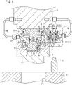
- FIG. 1 to FIG. 6 show a first embodiment of the present invention.
- a tool changer serving as a clamping apparatus of the first embodiment is used to attach/detach a tool 1 such as a machine tool and a jig to/from a robot arm 2.
- the tool changer is configured as follows, for example.
- a master cylinder 3 functioning as a first block is fixed to a leading end portion of the robot arm 2.
- a tool adapter 4 functioning as a second block is fixed to an end portion of the tool 1.
- the tool adapter 4 has a recess 5, in which a tapered hole 6 for positioning and an engaged portion 7 for clamping are provided in this order from an opening side to a bottom side of the recess 5.
- a piston main body 9 of a piston 8 is hermetically inserted in a bottom-side portion in the master cylinder 3 so as to be movable in an axial direction of the piston 8.
- a lock chamber 10 is provided on a forward side relative to the piston main body 9, while a release chamber 11 is provided on a backward side relative to the piston main body 9.
- the lock chamber 10 is communicatively connected to a lock port 13 provided on a first side surface of the master cylinder 3 via a passage 12.
- the release chamber 11 is communicatively connected to a release port 15 provided on a second side surface of the master cylinder 3 via a passage 14. Compressed air functioning as pressure fluid is supplied to and discharged from the lock port 13 and the release port 15.
- a tubular plug portion 16 which is unitary with the master cylinder 3, protrudes outward from the master cylinder 3.
- the plug portion 16 is configured to be inserted in the recess 5 of the tool adapter 4.
- An output rod portion 17 of the piston 8 is inserted in a tubular hole 16a of the plug portion 16 so as to be movable in the axial direction.
- the piston 8 including the output rod portion 17 and the piston main body 9 may be a unitary element made of one material, or may be structured by connecting separately-made components together.
- a plurality of through holes 18 are bored through a leading end portion of a peripheral wall of the plug portion 16, at predetermined intervals with respect to its circumferential direction.
- An engagement ball 19 is supported in each of the through holes 18 so as to be movable between a radially outward engaged position (see FIG. 1 ) and a radially inward disengaged position.
- radially means a radial direction of the output rod portion 17.
- a pushing surface 20 and a retraction groove 21 are provided on a leading end portion of an outer peripheral surface of the output rod portion 17.
- Each pushing surface 20 and its corresponding retraction groove 21 are continuous with each other in the axial direction.
- the engagement balls 19 are an example of an engaging means configured to pull the tool adapter 4 toward the master cylinder 3 and to fix the tool adapter 4, through the backward movement of the output rod portion 17.
- a straight inner peripheral surface 23a of the sleeve 23 is supported by an outer peripheral surface of the plug portion 16 so as to be movable in the axial direction.
- a tapered outer peripheral surface 23b of the sleeve 23 is configured to be engageable with the tapered hole 6 of the tool adapter 4.
- the sleeve 23 of this embodiment has a slit 23c at a part of its peripheral wall.
- the sleeve 23 This allows the sleeve 23 to contract when an external force is exerted on the tapered outer peripheral surface 23b, and to expand due to its elastic restoring force when the external force is lifted.
- a base end portion of the sleeve 23 is inserted in an annular groove 24 provided on a leading end surface of the master cylinder 3.
- a sleeve advancing means configured to push the sleeve 23 toward a leading end side is provided.
- the sleeve advancing means is structured as follows.
- a blind hole 25 is provided so as to open onto a surface of the piston main body 9, which is close to the lock chamber 10.
- a recess 26 opposed to the hole 25 is provided in the lock chamber 10.
- a pushing member 28 is hermetically inserted in the through hole 27 via a sealing member 29, and a leading end of the pushing member 28 is opposed to the sleeve 23.
- An advance spring 30 is disposed between a spring receiver 28a provided on a base end portion of the pushing member 28 and a bottom surface of the hole 25. Due to this arrangement, the advance spring 30 biases the sleeve 23 toward the leading end side via the pushing member 28.
- a retaining ring 49 provided on the outer periphery of the plug portion 16 prevents the sleeve 23 from moving toward the leading end side more than a predetermined distance.
- a valve case 31 is provided on the second side surface of the master cylinder 3, on which the release port 15 is provided.
- the valve case 31 includes: a valve case main body 32; and a tubular lid member 33 screwed and fixed to the valve case main body 32 via a sealing member 47.
- a primary-side pressure fluid supply/discharge port 34 is provided on a first side surface of the valve case main body 32.
- a secondary-side pressure fluid supply/discharge port 35 is provided on a second side surface of the valve case main body 32, which is opposite from the first side surface.
- the secondary-side pressure fluid supply/discharge port 35 is connected to the release port 15.
- a pressure fluid discharge port 36 through which compressed air is discharged is provided on an axial end surface of the lid member 33.
- a valve member 37 is disposed in the valve case main body 32.
- a rod-like pusher 38 functioning as an operation portion and protruding from the valve case main body 32, is provided at an axial end portion of the valve member 37.
- the pusher 38 is hermetically inserted in a through hole 32a bored through the valve case main body 32 via a sealing member 39.
- the valve member 37 has a valve element body 40 having a diameter larger than that of the pusher 38.
- An annular elastic member 41 is attached in an annular groove 40a provided on an outer peripheral surface of the valve element body 40.
- a tapered valve seat 42 is provided on an inner peripheral surface of the lid member 33. The elastic member 41 is configured to be pressed onto the valve seat 42.
- a communication passage 43 which communicatively connects the primary-side pressure fluid supply/discharge port 34 to the secondary-side pressure fluid supply/discharge port 35, is provided on a first side close to the pusher 38 relative to the valve element body 40.
- the communication passage 43 may be or may not be closed by contact between the valve element body 40 and a ring member 44 disposed on a bottom portion of the valve case main body 32. Even in the arrangement in which the communication passage 43 is closed by the contact between the ring member 44 and the valve element body 40, the communication passage 43 is opened when the pusher 38 is pushed into the valve case main body 32.
- a pressure fluid discharge chamber 45 which is communicatively connected to the pressure fluid discharge port 36, is provided on a second side, which is opposite from the pusher 38, i.e., from the first side relative to the valve element body 40.
- a spring 46 functioning as a biasing means is disposed in the pressure fluid discharge chamber 45. The spring 46 biases the valve element body 40 in a direction in which the pusher 38 protrudes from the valve case main body 32.
- the tool changer having the above-described structure operates as follows.
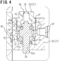
- valve member 37 in the valve case 31 is biased by the spring 46, and the pusher 38 provided at its axial end portion protrudes from the valve case main body 32. Meanwhile, a gap is created between the valve element body 40 (the elastic member 41 attached to the valve element body 40) and the valve seat 42, and therefore communication between: each of the primary-side pressure fluid supply/discharge port 34 and the secondary-side pressure fluid supply/discharge port 35; and the pressure fluid discharge port 36 is open. Because of this, even if compressed air is supplied to the primary-side pressure fluid supply/discharge port 34 from the robot arm 2 side through a pipe 50 due to an operating error, the compressed air is discharged from the pressure fluid discharge port 36.
- the pressure in the release chamber 11 does not increase because the communication between the release chamber 11 and the pressure fluid discharge port 36 is kept open via the passage 14, the secondary-side pressure fluid supply/discharge port 35, and the like. Due to these, the piston 8 (piston main body 9) does not descend. As a result, the tool 1 is kept fixed to the robot arm 2.
- the tool 1 When detaching the tool 1 from the robot arm 2, first of all, the tool 1 is fitted in a recess 51a of a tool stocker 51 by operating the robot arm 2. In the vicinity of the recess 51a, a pusher pressing member 52, with which the pusher 38 is pushed into the valve case 31, is provided on a top surface of the tool stocker 51.
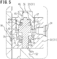
- the elastic member 41 attached to the valve element body 40 is pressed onto the valve seat 42 provided on an inner peripheral surface of the valve case 31, and the device transitions from a first state, in which communication between: each of the primary-side pressure fluid supply/discharge port 34 and the secondary-side pressure fluid supply/discharge port 35 (communication passage 43); and the pressure fluid discharge port 36 is open, to a second state, in which communication between: each of the primary-side pressure fluid supply/discharge port 34 and the secondary-side pressure fluid supply/discharge port 35 (communication passage 43); and the pressure fluid discharge port 36 is closed while the flow of compressed air from the primary-side pressure fluid supply/discharge port 34 to the secondary-side pressure fluid supply/discharge port 35 is allowed.
- the following describes operations of the tool changer at the time of attaching the tool 1 to the robot arm 2.
- the leading end portion of the robot arm 2 is lowered, and the plug portion 16 protruding from the master cylinder 3 is inserted into the recess 5 of the tool adapter 4.
- the plug portion 16 is inserted, the leading end of the output rod portion 17 is brought into contact with the bottom surface of the recess 5 of the tool adapter 4.
- compressed air is discharged from the release chamber 11, while compressed air is supplied to the lock chamber 10.
- the piston main body 9 raises the output rod portion 17 due to the increased pressure in the lock chamber 10.
- the pushing surface 20 provided on the outer peripheral surface of the output rod portion 17 pushes the engagement balls 19 outward in the radial direction, and the radial pushing force is converted to an upward force via the engaged portion 7. Due to the upward force, the tool adapter 4 is pulled upward. Then, the tapered hole 6 of the tool adapter 4 makes a tapering engagement with the tapered outer peripheral surface 23b of the sleeve 23, to cause the sleeve 23 to contract.
- the axis of the tapered hole 6 is aligned with the axis of the plug portion 16, and a top surface of the tool adapter 4 is received by an under surface of the master cylinder 3. The tool 1 is thus aligned with and attached to the robot arm 2.
- FIG. 7 shows a second embodiment of the present invention.
- the second embodiment is different from the first embodiment in that the secondary-side pressure fluid supply/discharge port 35 provided on the surface of the valve case main body 32 is connected to the lock port 13, not to the release port 15, in the second embodiment.
- compressed air for releasing is supplied to and discharged from the pipe 48 connected to the release port 15, while compressed air for locking is supplied to and discharged from the pipe 50 connected to the primary-side pressure fluid supply/discharge port 34.
- the piston 8 (the piston main body 9, the output rod portion 17) does not ascend, because compressed air is discharged from the pressure fluid discharge port 36 and therefore the pressure does not increase in the lock chamber 10. Because the output rod portion 17 does not ascend, the engagement balls 19 are not pushed outward by the pushing surface 20 of the output rod portion 17 and do not protrude outward in the radial direction relative to the plug portion 16.
- valve member 37 is actuated by pressing an operation portion (the pusher 38) of the valve member 37 onto a fixed object (the pusher pressing member 52).
- the valve member 37 may be actuated by pushing the pusher 38 with a human finger or with a peripheral device, into the valve case 31.
- the pusher 38 may protrude from a side or top surface of the valve case 31, instead of the under surface of the valve case 31.
- any of the sleeve 23 and the sleeve advancing means does not have to be provided.
- a collet configured to be engaged with a straight engaged hole by virtue of friction, plastic deformation, or the like may be used instead of the engagement balls 19 configured to be engaged with the tapered hole like engaged portion 7.
- the positions of the lock chamber 10 and the release chamber 11 may be replaced with each other. That is, the following arrangement is possible: the lock chamber 10 is provided on the backward side relative to the piston main body 9, while the release chamber 11 is provided on the forward side relative to the piston main body 9.
- the pushing surface 20 on the leading end portion of the outer peripheral surface of the output rod portion 17 is designed so as to taper down toward the leading end side (so that its diameter decreases toward the leading end side). As compressed air is supplied to the lock chamber 10, the output rod portion 17 moves forward (descends), to fix the tool 1 to the robot arm 2.
- gas such as nitrogen gas or liquid such as pressurized oil may be used as pressure fluid.
- the tool changer of the each of the above embodiments is a clamping apparatus, through which the tool 1 such as a machine tool and a jig is attached to/detached from the robot arm 2.
- the clamping apparatus of the present invention can be used also as a clamping apparatus configured to detachably fix a pallet or the like to a table or the like.
Landscapes
- Engineering & Computer Science (AREA)
- Mechanical Engineering (AREA)
- Robotics (AREA)
- Manipulator (AREA)
- Jigs For Machine Tools (AREA)
Applications Claiming Priority (2)
| Application Number | Priority Date | Filing Date | Title |
|---|---|---|---|
| JP2019195284 | 2019-10-28 | ||
| PCT/JP2020/038559 WO2021085110A1 (ja) | 2019-10-28 | 2020-10-13 | クランプ装置 |
Publications (2)
| Publication Number | Publication Date |
|---|---|
| EP4052841A1 true EP4052841A1 (de) | 2022-09-07 |
| EP4052841A4 EP4052841A4 (de) | 2022-12-14 |
Family
ID=75716177
Family Applications (1)
| Application Number | Title | Priority Date | Filing Date |
|---|---|---|---|
| EP20882444.1A Pending EP4052841A4 (de) | 2019-10-28 | 2020-10-13 | Spannvorrichtung |
Country Status (7)
| Country | Link |
|---|---|
| US (1) | US12134157B2 (de) |
| EP (1) | EP4052841A4 (de) |
| JP (1) | JP7508125B2 (de) |
| KR (1) | KR102580656B1 (de) |
| CN (1) | CN114630730B (de) |
| TW (1) | TWI756873B (de) |
| WO (1) | WO2021085110A1 (de) |
Cited By (1)
| Publication number | Priority date | Publication date | Assignee | Title |
|---|---|---|---|---|
| EP4434692A1 (de) * | 2023-03-23 | 2024-09-25 | Klose & Oechsle GmbH | Halterungsvorrichtung zur halterung einer anschlussleitung an einem beweglichen roboterarm |
Families Citing this family (5)
| Publication number | Priority date | Publication date | Assignee | Title |
|---|---|---|---|---|
| JP7508125B2 (ja) * | 2019-10-28 | 2024-07-01 | 株式会社コスメック | クランプ装置 |
| CN114619422B (zh) * | 2022-03-22 | 2024-05-31 | 苏州宛弘智能装备有限公司 | 三轴模块化组合的直角坐标机器人 |
| JP2024048226A (ja) * | 2022-09-27 | 2024-04-08 | 株式会社コスメック | 部材交換装置 |
| CN117002986B (zh) * | 2023-08-08 | 2026-02-24 | 广州华德汽车弹簧有限公司 | 一种稳定杆搬运机械手 |
| DE102024002082B4 (de) * | 2024-06-26 | 2026-01-08 | Günther Zimmer | Austauschadaptersystem |
Family Cites Families (28)
| Publication number | Priority date | Publication date | Assignee | Title |
|---|---|---|---|---|
| US512313A (en) * | 1894-01-09 | Pneumatic jack | ||
| JPS5690275U (de) | 1979-12-12 | 1981-07-18 | ||
| JP2583747Y2 (ja) * | 1992-06-25 | 1998-10-27 | カヤバ工業株式会社 | 保護回路付フィルタ装置 |
| JPH067809A (ja) * | 1992-06-25 | 1994-01-18 | Kawasaki Steel Corp | 高潤滑対応圧延機 |
| JP2603580Y2 (ja) * | 1992-08-14 | 2000-03-15 | 株式会社牧野フライス製作所 | 傾斜テーブルにおけるパレット落下防止装置 |
| CN2142902Y (zh) * | 1992-09-23 | 1993-09-29 | 杨世平 | 继动安全阀 |
| JP3338669B2 (ja) * | 1999-08-03 | 2002-10-28 | 株式会社コスメック | データム機能付きクランプ装置 |
| JP3671218B2 (ja) * | 2002-04-24 | 2005-07-13 | 独立行政法人 宇宙航空研究開発機構 | 分離可能な係留装置 |
| ATE362820T1 (de) * | 2002-08-06 | 2007-06-15 | Kosmek Ltd | Klemmvorrichtung |
| JP4311616B2 (ja) * | 2003-01-24 | 2009-08-12 | 株式会社コスメック | バネロック式クランプ装置 |
| WO2004067224A1 (ja) * | 2003-01-29 | 2004-08-12 | Kosmek Ltd. | クランプ装置およびその装置を利用したクランピングシステム |
| KR101083525B1 (ko) * | 2003-09-26 | 2011-11-16 | 가부시키가이샤 코스멕 | 클램프 장치 |
| CN1874664B (zh) * | 2005-05-30 | 2010-07-14 | 尼柯斯有限公司 | 固定器 |
| US20090152784A1 (en) * | 2006-06-13 | 2009-06-18 | Keitaro Yonezawa | Swing clamp |
| CN102256741A (zh) * | 2008-12-17 | 2011-11-23 | 克斯美库股份有限公司 | 带液力耦合器的紧固系统 |
| EP2489464B1 (de) | 2009-10-13 | 2013-12-04 | Kosmek Ltd. | Spannvorrichtung |
| JP4945681B1 (ja) * | 2010-11-24 | 2012-06-06 | 株式会社コスメック | 倍力機構付きシリンダ装置 |
| WO2012073723A1 (ja) * | 2010-12-02 | 2012-06-07 | 株式会社コスメック | クランプ装置 |
| JP5827602B2 (ja) * | 2012-06-28 | 2015-12-02 | 株式会社コスメック | クランプ装置 |
| JP6208480B2 (ja) * | 2013-06-11 | 2017-10-04 | 株式会社コスメック | 倍力機構付きシリンダ装置 |
| JP5666660B2 (ja) * | 2013-07-26 | 2015-02-12 | パスカルエンジニアリング株式会社 | 位置検知装置 |
| JP6274798B2 (ja) * | 2013-09-20 | 2018-02-07 | Kyb株式会社 | 緩衝装置 |
| JP6551740B2 (ja) * | 2015-10-28 | 2019-07-31 | Smc株式会社 | 流体制御弁 |
| JP6688644B2 (ja) * | 2016-03-02 | 2020-04-28 | 株式会社コスメック | リフト機能付きクランプ装置 |
| CN210148924U (zh) | 2019-01-04 | 2020-03-17 | 伊利诺斯工具制品有限公司 | 真空擦拭器及具有真空擦拭器的模板印刷机 |
| JP7508125B2 (ja) * | 2019-10-28 | 2024-07-01 | 株式会社コスメック | クランプ装置 |
| DE212021000326U1 (de) * | 2020-03-06 | 2022-12-13 | Kosmek Ltd. | Klemmvorrichtung |
| JP2024048226A (ja) * | 2022-09-27 | 2024-04-08 | 株式会社コスメック | 部材交換装置 |
-
2020
- 2020-10-13 JP JP2021554301A patent/JP7508125B2/ja active Active
- 2020-10-13 EP EP20882444.1A patent/EP4052841A4/de active Pending
- 2020-10-13 WO PCT/JP2020/038559 patent/WO2021085110A1/ja not_active Ceased
- 2020-10-13 KR KR1020227010055A patent/KR102580656B1/ko active Active
- 2020-10-13 CN CN202080074552.0A patent/CN114630730B/zh active Active
- 2020-10-13 US US17/771,952 patent/US12134157B2/en active Active
- 2020-10-20 TW TW109136201A patent/TWI756873B/zh active
Cited By (1)
| Publication number | Priority date | Publication date | Assignee | Title |
|---|---|---|---|---|
| EP4434692A1 (de) * | 2023-03-23 | 2024-09-25 | Klose & Oechsle GmbH | Halterungsvorrichtung zur halterung einer anschlussleitung an einem beweglichen roboterarm |
Also Published As
| Publication number | Publication date |
|---|---|
| CN114630730A (zh) | 2022-06-14 |
| TWI756873B (zh) | 2022-03-01 |
| JP7508125B2 (ja) | 2024-07-01 |
| JPWO2021085110A1 (de) | 2021-05-06 |
| KR20220048485A (ko) | 2022-04-19 |
| US12134157B2 (en) | 2024-11-05 |
| US20220371137A1 (en) | 2022-11-24 |
| KR102580656B1 (ko) | 2023-09-21 |
| CN114630730B (zh) | 2024-07-02 |
| EP4052841A4 (de) | 2022-12-14 |
| WO2021085110A1 (ja) | 2021-05-06 |
| TW202126424A (zh) | 2021-07-16 |
Similar Documents
| Publication | Publication Date | Title |
|---|---|---|
| US12134157B2 (en) | Clamping apparatus | |
| CN1856384B (zh) | 夹持装置 | |
| JP4086281B2 (ja) | クランプ装置 | |
| JP4302174B1 (ja) | クランプ装置 | |
| EP0092967B1 (de) | Automatische Greifhand-Wechselvorrichtung für Industrieroboter | |
| CN104647052B (zh) | 夹紧装置 | |
| CN108698180B (zh) | 具有举起功能的夹紧装置 | |
| EP2246608A1 (de) | Vorrichtung zum anschliessen eines flüssigkeitskanals | |
| US7165763B2 (en) | Positioning device | |
| JP2009136942A (ja) | ロボットアームカップリング装置の脱落防止装置 | |
| KR101083486B1 (ko) | 위치결정장치 및 이를 구비한 클램핑 시스템 | |
| EP4545247A1 (de) | Vorrichtung zum ersetzen eines elements | |
| GB2347171A (en) | Pin locking assembly | |
| EP4534239A1 (de) | Klemmvorrichtung | |
| US12115615B2 (en) | Work support | |
| EP3815841B1 (de) | Werkstückhalterung | |
| US20220074436A1 (en) | Pneumatic cylinder device with holding valve | |
| JP6335059B2 (ja) | 検査装置及び検査方法 | |
| JP2009136941A (ja) | ロボットアームカップリング装置の脱落防止装置 | |
| US20210190098A1 (en) | Cylinder device | |
| JP2003266263A (ja) | データム機能付きクランプ装置 | |
| JP2003019631A (ja) | データム機能付きクランプ装置 | |
| JP7236721B2 (ja) | 固定装置、および当該固定装置を備えた固定システム | |
| JP2009214293A5 (de) | ||
| WO2023162801A1 (ja) | クランプ装置 |
Legal Events
| Date | Code | Title | Description |
|---|---|---|---|
| STAA | Information on the status of an ep patent application or granted ep patent |
Free format text: STATUS: THE INTERNATIONAL PUBLICATION HAS BEEN MADE |
|
| PUAI | Public reference made under article 153(3) epc to a published international application that has entered the european phase |
Free format text: ORIGINAL CODE: 0009012 |
|
| STAA | Information on the status of an ep patent application or granted ep patent |
Free format text: STATUS: REQUEST FOR EXAMINATION WAS MADE |
|
| 17P | Request for examination filed |
Effective date: 20220324 |
|
| AK | Designated contracting states |
Kind code of ref document: A1 Designated state(s): AL AT BE BG CH CY CZ DE DK EE ES FI FR GB GR HR HU IE IS IT LI LT LU LV MC MK MT NL NO PL PT RO RS SE SI SK SM TR |
|
| A4 | Supplementary search report drawn up and despatched |
Effective date: 20221115 |
|
| RIC1 | Information provided on ipc code assigned before grant |
Ipc: B23Q 5/58 20060101ALI20221109BHEP Ipc: B23Q 1/00 20060101ALI20221109BHEP Ipc: B25J 15/04 20060101ALI20221109BHEP Ipc: B23Q 3/06 20060101ALI20221109BHEP Ipc: B23Q 3/02 20060101AFI20221109BHEP |
|
| DAV | Request for validation of the european patent (deleted) | ||
| DAX | Request for extension of the european patent (deleted) | ||
| STAA | Information on the status of an ep patent application or granted ep patent |
Free format text: STATUS: EXAMINATION IS IN PROGRESS |
|
| 17Q | First examination report despatched |
Effective date: 20250514 |