EP4053962A1 - Steuervorrichtung für eine simulierte batterie, elektronisches gerät, ladegerät und simuliertes batteriesteuerungsverfahren - Google Patents
Steuervorrichtung für eine simulierte batterie, elektronisches gerät, ladegerät und simuliertes batteriesteuerungsverfahren Download PDFInfo
- Publication number
- EP4053962A1 EP4053962A1 EP21744697.0A EP21744697A EP4053962A1 EP 4053962 A1 EP4053962 A1 EP 4053962A1 EP 21744697 A EP21744697 A EP 21744697A EP 4053962 A1 EP4053962 A1 EP 4053962A1
- Authority
- EP
- European Patent Office
- Prior art keywords
- electronic apparatus
- control element
- secondary battery
- battery
- simulated
- Prior art date
- Legal status (The legal status is an assumption and is not a legal conclusion. Google has not performed a legal analysis and makes no representation as to the accuracy of the status listed.)
- Pending
Links
Images


Classifications
-
- H—ELECTRICITY
- H01—ELECTRIC ELEMENTS
- H01M—PROCESSES OR MEANS, e.g. BATTERIES, FOR THE DIRECT CONVERSION OF CHEMICAL ENERGY INTO ELECTRICAL ENERGY
- H01M10/00—Secondary cells; Manufacture thereof
- H01M10/05—Accumulators with non-aqueous electrolyte
- H01M10/052—Li-accumulators
-
- G—PHYSICS
- G01—MEASURING; TESTING
- G01R—MEASURING ELECTRIC VARIABLES; MEASURING MAGNETIC VARIABLES
- G01R31/00—Arrangements for testing electric properties; Arrangements for locating electric faults; Arrangements for electrical testing characterised by what is being tested not provided for elsewhere
- G01R31/36—Arrangements for testing, measuring or monitoring the electrical condition of accumulators or electric batteries, e.g. capacity or state of charge [SoC]
- G01R31/367—Software therefor, e.g. for battery testing using modelling or look-up tables
-
- G—PHYSICS
- G01—MEASURING; TESTING
- G01R—MEASURING ELECTRIC VARIABLES; MEASURING MAGNETIC VARIABLES
- G01R31/00—Arrangements for testing electric properties; Arrangements for locating electric faults; Arrangements for electrical testing characterised by what is being tested not provided for elsewhere
- G01R31/36—Arrangements for testing, measuring or monitoring the electrical condition of accumulators or electric batteries, e.g. capacity or state of charge [SoC]
- G01R31/371—Arrangements for testing, measuring or monitoring the electrical condition of accumulators or electric batteries, e.g. capacity or state of charge [SoC] with remote indication, e.g. on external chargers
-
- G—PHYSICS
- G01—MEASURING; TESTING
- G01R—MEASURING ELECTRIC VARIABLES; MEASURING MAGNETIC VARIABLES
- G01R31/00—Arrangements for testing electric properties; Arrangements for locating electric faults; Arrangements for electrical testing characterised by what is being tested not provided for elsewhere
- G01R31/36—Arrangements for testing, measuring or monitoring the electrical condition of accumulators or electric batteries, e.g. capacity or state of charge [SoC]
- G01R31/374—Arrangements for testing, measuring or monitoring the electrical condition of accumulators or electric batteries, e.g. capacity or state of charge [SoC] with means for correcting the measurement for temperature or ageing
-
- G—PHYSICS
- G01—MEASURING; TESTING
- G01R—MEASURING ELECTRIC VARIABLES; MEASURING MAGNETIC VARIABLES
- G01R31/00—Arrangements for testing electric properties; Arrangements for locating electric faults; Arrangements for electrical testing characterised by what is being tested not provided for elsewhere
- G01R31/36—Arrangements for testing, measuring or monitoring the electrical condition of accumulators or electric batteries, e.g. capacity or state of charge [SoC]
- G01R31/382—Arrangements for monitoring battery or accumulator variables, e.g. SoC
- G01R31/3842—Arrangements for monitoring battery or accumulator variables, e.g. SoC combining voltage and current measurements
-
- H—ELECTRICITY
- H01—ELECTRIC ELEMENTS
- H01M—PROCESSES OR MEANS, e.g. BATTERIES, FOR THE DIRECT CONVERSION OF CHEMICAL ENERGY INTO ELECTRICAL ENERGY
- H01M10/00—Secondary cells; Manufacture thereof
- H01M10/42—Methods or arrangements for servicing or maintenance of secondary cells or secondary half-cells
- H01M10/425—Structural combination with electronic components, e.g. electronic circuits integrated to the outside of the casing
-
- H—ELECTRICITY
- H01—ELECTRIC ELEMENTS
- H01M—PROCESSES OR MEANS, e.g. BATTERIES, FOR THE DIRECT CONVERSION OF CHEMICAL ENERGY INTO ELECTRICAL ENERGY
- H01M10/00—Secondary cells; Manufacture thereof
- H01M10/42—Methods or arrangements for servicing or maintenance of secondary cells or secondary half-cells
- H01M10/44—Methods for charging or discharging
-
- H—ELECTRICITY
- H01—ELECTRIC ELEMENTS
- H01M—PROCESSES OR MEANS, e.g. BATTERIES, FOR THE DIRECT CONVERSION OF CHEMICAL ENERGY INTO ELECTRICAL ENERGY
- H01M10/00—Secondary cells; Manufacture thereof
- H01M10/42—Methods or arrangements for servicing or maintenance of secondary cells or secondary half-cells
- H01M10/46—Accumulators structurally combined with charging apparatus
-
- H—ELECTRICITY
- H01—ELECTRIC ELEMENTS
- H01M—PROCESSES OR MEANS, e.g. BATTERIES, FOR THE DIRECT CONVERSION OF CHEMICAL ENERGY INTO ELECTRICAL ENERGY
- H01M10/00—Secondary cells; Manufacture thereof
- H01M10/42—Methods or arrangements for servicing or maintenance of secondary cells or secondary half-cells
- H01M10/48—Accumulators combined with arrangements for measuring, testing or indicating the condition of cells, e.g. the level or density of the electrolyte
- H01M10/486—Accumulators combined with arrangements for measuring, testing or indicating the condition of cells, e.g. the level or density of the electrolyte for measuring temperature
-
- H—ELECTRICITY
- H02—GENERATION; CONVERSION OR DISTRIBUTION OF ELECTRIC POWER
- H02J—ELECTRIC POWER NETWORKS; CIRCUIT ARRANGEMENTS OR SYSTEMS FOR SUPPLYING OR DISTRIBUTING ELECTRIC POWER; SYSTEMS FOR STORING ELECTRIC ENERGY
- H02J7/00—Circuit arrangements for charging or discharging batteries or for supplying loads from batteries
- H02J7/40—Circuit arrangements for charging or discharging batteries or for supplying loads from batteries characterised by the exchange of charge or discharge related data
- H02J7/42—Circuit arrangements for charging or discharging batteries or for supplying loads from batteries characterised by the exchange of charge or discharge related data with electronic devices having internal batteries, e.g. mobile phones
-
- H—ELECTRICITY
- H02—GENERATION; CONVERSION OR DISTRIBUTION OF ELECTRIC POWER
- H02J—ELECTRIC POWER NETWORKS; CIRCUIT ARRANGEMENTS OR SYSTEMS FOR SUPPLYING OR DISTRIBUTING ELECTRIC POWER; SYSTEMS FOR STORING ELECTRIC ENERGY
- H02J7/00—Circuit arrangements for charging or discharging batteries or for supplying loads from batteries
- H02J7/40—Circuit arrangements for charging or discharging batteries or for supplying loads from batteries characterised by the exchange of charge or discharge related data
- H02J7/44—Circuit arrangements for charging or discharging batteries or for supplying loads from batteries characterised by the exchange of charge or discharge related data between battery management systems and power sources
-
- H—ELECTRICITY
- H02—GENERATION; CONVERSION OR DISTRIBUTION OF ELECTRIC POWER
- H02J—ELECTRIC POWER NETWORKS; CIRCUIT ARRANGEMENTS OR SYSTEMS FOR SUPPLYING OR DISTRIBUTING ELECTRIC POWER; SYSTEMS FOR STORING ELECTRIC ENERGY
- H02J7/00—Circuit arrangements for charging or discharging batteries or for supplying loads from batteries
- H02J7/485—Circuit arrangements for charging or discharging batteries or for supplying loads from batteries with provisions for charging different types of batteries
-
- H—ELECTRICITY
- H02—GENERATION; CONVERSION OR DISTRIBUTION OF ELECTRIC POWER
- H02J—ELECTRIC POWER NETWORKS; CIRCUIT ARRANGEMENTS OR SYSTEMS FOR SUPPLYING OR DISTRIBUTING ELECTRIC POWER; SYSTEMS FOR STORING ELECTRIC ENERGY
- H02J7/00—Circuit arrangements for charging or discharging batteries or for supplying loads from batteries
- H02J7/80—Circuit arrangements for charging or discharging batteries or for supplying loads from batteries including monitoring or indicating arrangements
-
- H—ELECTRICITY
- H02—GENERATION; CONVERSION OR DISTRIBUTION OF ELECTRIC POWER
- H02J—ELECTRIC POWER NETWORKS; CIRCUIT ARRANGEMENTS OR SYSTEMS FOR SUPPLYING OR DISTRIBUTING ELECTRIC POWER; SYSTEMS FOR STORING ELECTRIC ENERGY
- H02J7/00—Circuit arrangements for charging or discharging batteries or for supplying loads from batteries
- H02J7/90—Regulation of charging or discharging current or voltage
- H02J7/933—Regulation of charging or discharging current or voltage the cycle being controlled or terminated in response to electric parameters
-
- H—ELECTRICITY
- H02—GENERATION; CONVERSION OR DISTRIBUTION OF ELECTRIC POWER
- H02J—ELECTRIC POWER NETWORKS; CIRCUIT ARRANGEMENTS OR SYSTEMS FOR SUPPLYING OR DISTRIBUTING ELECTRIC POWER; SYSTEMS FOR STORING ELECTRIC ENERGY
- H02J7/00—Circuit arrangements for charging or discharging batteries or for supplying loads from batteries
- H02J7/90—Regulation of charging or discharging current or voltage
- H02J7/971—Regulation of charging or discharging current or voltage the charge cycle being controlled or terminated in response to non-electric parameters
-
- G—PHYSICS
- G01—MEASURING; TESTING
- G01R—MEASURING ELECTRIC VARIABLES; MEASURING MAGNETIC VARIABLES
- G01R31/00—Arrangements for testing electric properties; Arrangements for locating electric faults; Arrangements for electrical testing characterised by what is being tested not provided for elsewhere
- G01R31/36—Arrangements for testing, measuring or monitoring the electrical condition of accumulators or electric batteries, e.g. capacity or state of charge [SoC]
- G01R31/389—Measuring internal impedance, internal conductance or related variables
-
- G—PHYSICS
- G01—MEASURING; TESTING
- G01R—MEASURING ELECTRIC VARIABLES; MEASURING MAGNETIC VARIABLES
- G01R31/00—Arrangements for testing electric properties; Arrangements for locating electric faults; Arrangements for electrical testing characterised by what is being tested not provided for elsewhere
- G01R31/36—Arrangements for testing, measuring or monitoring the electrical condition of accumulators or electric batteries, e.g. capacity or state of charge [SoC]
- G01R31/392—Determining battery ageing or deterioration, e.g. state of health
-
- H—ELECTRICITY
- H01—ELECTRIC ELEMENTS
- H01M—PROCESSES OR MEANS, e.g. BATTERIES, FOR THE DIRECT CONVERSION OF CHEMICAL ENERGY INTO ELECTRICAL ENERGY
- H01M10/00—Secondary cells; Manufacture thereof
- H01M10/42—Methods or arrangements for servicing or maintenance of secondary cells or secondary half-cells
- H01M10/425—Structural combination with electronic components, e.g. electronic circuits integrated to the outside of the casing
- H01M2010/4271—Battery management systems including electronic circuits, e.g. control of current or voltage to keep battery in healthy state, cell balancing
-
- H—ELECTRICITY
- H01—ELECTRIC ELEMENTS
- H01M—PROCESSES OR MEANS, e.g. BATTERIES, FOR THE DIRECT CONVERSION OF CHEMICAL ENERGY INTO ELECTRICAL ENERGY
- H01M10/00—Secondary cells; Manufacture thereof
- H01M10/42—Methods or arrangements for servicing or maintenance of secondary cells or secondary half-cells
- H01M10/425—Structural combination with electronic components, e.g. electronic circuits integrated to the outside of the casing
- H01M2010/4278—Systems for data transfer from batteries, e.g. transfer of battery parameters to a controller, data transferred between battery controller and main controller
-
- H—ELECTRICITY
- H01—ELECTRIC ELEMENTS
- H01M—PROCESSES OR MEANS, e.g. BATTERIES, FOR THE DIRECT CONVERSION OF CHEMICAL ENERGY INTO ELECTRICAL ENERGY
- H01M2220/00—Batteries for particular applications
- H01M2220/20—Batteries in motive systems, e.g. vehicle, ship, plane
-
- H—ELECTRICITY
- H01—ELECTRIC ELEMENTS
- H01M—PROCESSES OR MEANS, e.g. BATTERIES, FOR THE DIRECT CONVERSION OF CHEMICAL ENERGY INTO ELECTRICAL ENERGY
- H01M2220/00—Batteries for particular applications
- H01M2220/30—Batteries in portable systems, e.g. mobile phone, laptop
-
- Y—GENERAL TAGGING OF NEW TECHNOLOGICAL DEVELOPMENTS; GENERAL TAGGING OF CROSS-SECTIONAL TECHNOLOGIES SPANNING OVER SEVERAL SECTIONS OF THE IPC; TECHNICAL SUBJECTS COVERED BY FORMER USPC CROSS-REFERENCE ART COLLECTIONS [XRACs] AND DIGESTS
- Y02—TECHNOLOGIES OR APPLICATIONS FOR MITIGATION OR ADAPTATION AGAINST CLIMATE CHANGE
- Y02E—REDUCTION OF GREENHOUSE GAS [GHG] EMISSIONS, RELATED TO ENERGY GENERATION, TRANSMISSION OR DISTRIBUTION
- Y02E60/00—Enabling technologies; Technologies with a potential or indirect contribution to GHG emissions mitigation
- Y02E60/10—Energy storage using batteries
Definitions
- the present invention relates to a technique for simulating the performance of a secondary battery such as a lithium-ion battery.
- a capacitor capacitance value as a time constant element ranges from a few hundred F to a few thousand F. This value is a numerical value that cannot correspond to AC impedance and the equivalent circuit model thereof, which is a method for evaluating the AC characteristics of a battery, and it cannot be said that the properties of the battery are reproduced.
- Internal resistance is a characteristic of a secondary battery.
- a lithium-ion secondary battery hereinafter, referred to as a LIB secondary battery
- complicated chemical reactions such as an electrode reaction, an SEI reaction, and an ion diffusion reaction are intertwined inside the battery
- the behavior of a battery voltage is not the same as that of Ohm's law, considering internal resistance as a simple DC resistance.
- Patent Document 1 Japanese Patent No. 5924617
- a secondary battery is coupled to a load, and charging and discharging are repeated.
- voltage, current, and temperature are the basic information for knowing the state of the secondary battery.
- the output voltage of the battery is affected by the internal resistance, and the internal resistance itself also changes depending on the temperature conditions or the degree of deterioration of the battery, and a means for accurately reproducing the characteristics of the battery in an actual operating state is needed.
- an object of the present invention is to provide a device or the like capable of improving the convenience of reproduction under various conditions of the characteristics of a secondary battery by using a simulated battery.
- a simulated battery control device includes a first control element configured to identify a value of a parameter of a secondary battery model representing current dependence of an output voltage of a secondary battery mounted or to be mounted on an electronic apparatus as a power supply, based on communication with the electronic apparatus, a second control element configured to recognize a time series of command current values based on the communication with the electronic apparatus and to calculate a model output voltage as a change mode of a voltage output from the secondary battery model when the time series of the command current values is input to the secondary battery model of which the value of the parameter is recognized by the first control element, and a third control element configured to apply the model output voltage calculated by the second control element to a simulated battery mounted on the electronic apparatus or a power supply device for a specified load of the electronic apparatus, based on communication with the electronic apparatus or the power supply device as a charging power supply of the secondary battery.
- a simulated battery control method includes a first control step of identifying a value of a parameter of a secondary battery model representing current dependence of an output voltage of a secondary battery mounted or to be mounted on an electronic apparatus as a power supply, based on communication with the electronic apparatus, a second control step of recognizing a time series of command current values based on the communication with the electronic apparatus and calculating a model output voltage as a change mode of a voltage output from the secondary battery model when the time series of the command current values is input to the secondary battery model of which the value of the parameter is recognized in the first control step, and a third control step of applying the model output voltage calculated in the second control step to a simulated battery mounted on the electronic apparatus or a power supply device for a specified load of the electronic apparatus, based on the communication with the electronic apparatus or the power supply device as a charging power supply of the secondary battery.
- An electronic apparatus is an electronic apparatus on which a secondary battery is mounted as a power supply, including a simulated battery, a specified load, a first apparatus control element configured to cause a first control element constituting a simulated battery control device to identify a value of a parameter of a secondary battery model representing current dependence of an output voltage of the secondary battery based on communication with the simulated battery control device, a second apparatus control element configured to cause a second control element constituting the simulated battery control device to recognize a time series of command current values based on the communication with the simulated battery control device and to calculate a model output voltage as a change mode of a voltage output from the secondary battery model when the time series of the command current values is input to the secondary battery model of which the value of the parameter is recognized by the first control element, and a third apparatus control element configured to apply the model output voltage calculated by the second control element to the specified load from the simulated battery based on the communication with the simulated battery control device.
- the first apparatus control element causes the first control element to recognize a deterioration degree of the secondary battery based on the communication with the simulated battery control device, and identify a value corresponding to a difference in the deterioration degree as the value of the parameter of the secondary battery model.
- the first apparatus control element measures a temperature of the electronic apparatus or the simulated battery by using a temperature sensor, and causes the first control element to recognize a measurement result of the temperature of the electronic apparatus or the simulated battery based on the communication with simulated battery control device and identify a value corresponding to a difference in the measurement result of the temperature as the value of the parameter of the secondary battery model.
- the first apparatus control element causes the first control element to identify the value of the parameter of the secondary battery model
- the second apparatus control element causes the second control element to calculate the model output voltage provided that a first specified operation is performed through an input interface of the electronic apparatus.
- the first apparatus control element causes the first control element to identify the value of the parameter of the secondary battery model, and that the second apparatus control element causes the second control element to calculate the model output voltage provided that a power cut-off operation is performed through the input interface in the electronic apparatus as the first specified operation.
- the first apparatus control element causes the first control element to identify the value of the parameter of the secondary battery model, and that the second apparatus control element causes the second control element to calculate the model output voltage provided that the electronic apparatus is coupled to the charger.
- the third apparatus control element outputs information about operating characteristics of the specified load, when the model output voltage calculated by the second control element is applied to the simulated battery for the specified load of the electronic apparatus, to an output interface of the electronic apparatus.
- the third apparatus control element outputs the information about the operating characteristics of the specified load to the output interface based on the communication with the simulated battery control device provided that a second specified operation is performed through an input interface of the electronic apparatus.
- the third apparatus control element outputs the information about the operating characteristics of the specified load to the output interface based on the communication with the simulated battery control device provided that a wake operation of a sleep state of the output interface is performed through the input interface of the electronic apparatus as the second specified operation.
- the simulated battery is configured to be mounted as a replacement battery of the secondary battery.
- a charger is a charger that is coupled to an electronic apparatus on which a secondary battery is mounted as a power supply, including a simulated battery, a first charger control element configured to cause a first control element constituting a simulated battery control device to identify a value of a parameter of a secondary battery model representing current dependence of an output voltage of the secondary battery based on communication with the simulated battery control device, a second charger control element configured to cause a second control element constituting the simulated battery control device to recognize a time series of command current values based on the communication with the simulated battery control device to calculate a model output voltage as a change mode of a voltage output from the secondary battery model when the time series of the command current values is input to the secondary battery model of which the value of the parameter is recognized by the first control element, and a third charger control element configured to apply the model output voltage calculated by the second control element to a specified load of the electronic apparatus from the simulated battery based on the communication with the simulated battery control device.
- the first charger control element causes the first control element to recognize a deterioration degree of the secondary battery based on the communication with the simulated battery control device, and identify a value corresponding to a difference in the deterioration degree as the value of the parameter of the secondary battery model.
- the first charger control element measures a temperature of the electronic apparatus or the simulated battery by using a temperature sensor, and causes the first control element to recognize a measurement result of the temperature of the electronic apparatus or the simulated battery based on the communication with the simulated battery control device and identify a value corresponding to a difference in the measurement result of the temperature as the value of the parameter of the secondary battery model.
- the first charger control element causes the first control element to identify the value of the parameter of the secondary battery model
- the second charger control element causes the second control element to calculate the model output voltage provided that a first specified operation is performed through an input interface of the electronic apparatus.
- the first charger control element causes the first control element to identify the value of the parameter of the secondary battery model, and that the second charger control element causes the second control element to calculate the model output voltage provided that a power cut-off operation is performed through the input interface in the electronic apparatus as the first specified operation.
- the first charger control element causes the first control element to identify the value of the parameter of the secondary battery model, and that the second charger control element causes the second control element to calculate the model output voltage provided that the electronic apparatus is coupled to the charger.
- the third charger control element outputs information about operating characteristics of the specified load, when the model output voltage calculated by the second control element is applied to the simulated battery for the specified load of the electronic apparatus, to an output interface of the electronic apparatus.
- the third charger control element outputs the information about the operating characteristics of the specified load to the output interface based on the communication with the simulated battery control device provided that a second specified operation is performed through the input interface of the electronic apparatus.
- the third charger control element outputs the information about the operating characteristics of the specified load to the output interface based on the communication with the simulated battery control device provided that a wake operation of a sleep state of the output interface is performed through the input interface of the electronic apparatus as the second specified operation.
- the simulated battery is configured to be detachably mounted and configured to be mountable in electronic apparatus as a substitute battery for secondary batteries.
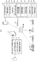
- a simulated battery control system as a first embodiment of the present invention illustrated in FIG. 1 includes a simulated battery control device 100 and an electronic apparatus 200 capable of communicating via a network to each other.
- the simulated battery control device 100 includes one or a plurality of servers that can access a database 10.
- the simulated battery control device 100 evaluates the performance of a secondary battery 240 mounted as a power supply in the electronic apparatus 200.
- the simulated battery control device 100 includes a first control element 110, a second control element 120, and a third control element 130.
- Each of the first control element 110, the second control element 120, and the third control element 130 include a processor (arithmetic processing unit), a memory (storage device), an I/O circuit, and the like.
- a memory or a storage device separate from the memory stores and holds various data such as a measurement result of the voltage response characteristics of the secondary battery 240 with respect to a current (for example, an impulse current), as well as a program or software.
- a current for example, an impulse current
- each of a plurality of identifiers for identifying the type (specified by the standard and specifications) of the secondary battery 240 or the electronic apparatus 200 on which the secondary battery 240 is mounted, and each of a plurality of secondary battery models are stored and held in a memory in association with each other.
- the processor reads the necessary programs and data from the memory, and based on the data, executes arithmetic processing according to the program, so that the arithmetic processing or task described later assigned to each of the elements 110, 120, and 130 can be executed.
- the electronic apparatus 200 includes an input interface 202, an output interface 204, a sensor group 206, an apparatus control unit 220, a simulated battery 230, the secondary battery 240, and a specified load 250.
- Any apparatus powered by the secondary battery 240 such as a personal computer, a mobile phone (smartphone), a home appliance, or a moving object such as an electric bicycle, falls under the electronic apparatus 200.
- the secondary battery 240 is charged when the electronic apparatus 200 is coupled to a charger 400 via a coupling terminal or is wirelessly coupled.
- the apparatus control unit 220 includes a first apparatus control element 221, a second apparatus control element 222, and a third apparatus control element 223.
- Each of the first apparatus control element 221 and the second apparatus control element 222 and the third apparatus control element 223 includes a processor (arithmetic processing unit), a memory (storage device), an I/O circuit, and the like.
- a memory or a storage device separate from the memory stores and holds various data such as a simulated battery identifier ID(m0), a simulated battery temperature T(m1), and a virtual deterioration degree D(m2) (see FIG. 3 /STEPS 214, 216, 218, and 220).
- the apparatus control unit 220 operates according to the power supplied from the secondary battery 240, and controls the operation of the electronic apparatus 200 in the energized state.
- "Recognizing" information by each element means performing all kinds of arithmetic processing to prepare necessary information, such as receiving information, retrieving or reading information from information sources such as the database 10, and calculating and estimating information based on other information.
- the operation of the electronic apparatus 200 includes the operation of an actuator (motorized actuator or the like) as the specified load 250 constituting the electronic apparatus 200.
- the processor constituting the apparatus control unit 220 reads necessary programs and data from the memory, and based on the data, executes the arithmetic processing assigned according to the program.
- the simulated battery 230 includes a D/A converter 231 and an amplifier 232.
- the D/A converter 231 performs D/A conversion.
- the amplifier 232 applies a voltage V(t) corresponding to the output from the D/A converter 231 to the electronic apparatus 200 or the load constituting the electronic apparatus 200.
- "(t)" means a value or a time series at time t.
- the calculator (second control element 120) equivalent to the secondary battery model includes a calculator 121, a model parameter setting element 122, an output device 123, and an adder 124.
- the calculator 121 calculates the output voltage derived from the virtual internal resistance of the simulated battery 230.
- the value of the parameter defining a transfer function H of the calculator 121 is set or changed by the model parameter setting element 122 based on a deterioration degree D(n2) of the virtual secondary battery simulated by the simulated battery 230.
- the output device 123 outputs a virtual open circuit voltage OCV(t) of the simulated battery 230.
- the adder 124 adds the outputs of the calculator 121 and the output device 123, respectively.
- the simulated battery 230 may be configured by an external power supply such as a commercial power supply to which the electronic apparatus 200 is coupled.
- the simulated battery 230 may be mounted on the electronic apparatus 200 instead of the secondary battery 240.
- the simulated battery 230 may include a second calculation element 122.
- the second calculation element 122 may be configured by a control device 210 constituting the electronic apparatus 200.
- the secondary battery 240 is, for example, a lithium-ion battery, and may be another secondary battery such as a nickel hydrogen battery or a nickel cadmium battery.
- the sensor group 206 measures the voltage response characteristics and temperature of the secondary battery 240, as well as the values of parameters necessary for controlling the electronic apparatus 200.
- the sensor group 206 includes, for example, a voltage sensor, a current sensor, and a temperature sensor that output signals corresponding to the voltage, current, and temperature of the secondary battery 240.
- the simulated battery control device 100 may be mounted on the electronic apparatus 200.
- a software server (not illustrated) may provide the function as the simulated battery control device 100 to an arithmetic processing unit by transmitting deterioration determination software to the arithmetic processing unit constituting the apparatus control unit 220 in the electronic apparatus 200.
- the operation control method or the construction method of the simulated battery 230 executed by the simulated battery control system of the first embodiment of the above configuration will be described with reference to the flowcharts illustrated in FIGS. 3 and 4 .
- the block "C ⁇ " is used for simplification, and refers to the transmission and/or reception of data and refers to a conditional branch that performs branch-direction processing on the condition that the data is transmitted and/or received.
- the first apparatus control element 221 determines whether or not the electronic apparatus 200 is coupled to the charger 400 ( FIG. 3 /STEP 210). If the determination result is negative ( FIG. 3 /STEP 210: NO), it is determined whether or not the electronic apparatus 200 is coupled to the charger 400 again after a series of processing is completed.
- the first apparatus control element 221 further determines whether or not a first specified operation is performed through the input interface 202( FIG. 3 /STEP 212). For example, an operation for switching the power of the electronic apparatus 200 from ON to OFF, an operation for switching the power of the electronic apparatus 200 from OFF to ON, an operation for stopping the operation of a predetermined application or the specified load 250 so that the arithmetic processing load such as CPU utilization and the like can be reduced to equal to or lower than a threshold, or an operation for starting a predetermined application or the specified load 250 corresponds to the "first specified operation".
- a first specified operation For example, an operation for switching the power of the electronic apparatus 200 from ON to OFF, an operation for switching the power of the electronic apparatus 200 from OFF to ON, an operation for stopping the operation of a predetermined application or the specified load 250 so that the arithmetic processing load such as CPU utilization and the like can be reduced to equal to or lower than a threshold, or an operation for starting a predetermined application or the specified load 250 corresponds to the
- the first apparatus control element 221 recognizes the battery identifier ID(m0) for identifying the type of the virtual secondary battery (or secondary battery 240) simulated by the simulated battery 230 ( FIG. 3 /STEP 214).
- the battery identifier ID(m0) may be recognized by the first apparatus control element 221 according to the type of the virtual secondary battery set through the input interface 202 of the electronic apparatus 200.
- the first apparatus control element 221 recognizes a temperature T(m1) of the virtual secondary battery simulated by the simulated battery 230 ( FIG. 3 /STEP 216). For example, the first apparatus control element 221 may recognize the temperature of the electronic apparatus 200 measured by the temperature sensor constituting the sensor group 206 of the electronic apparatus 200 as the temperature T(m1) of the virtual secondary battery. Further, the first apparatus control element 221 may recognize the temperature set through the input interface 202 of the electronic apparatus 200 as the temperature T(m1) of the virtual secondary battery.
- the first apparatus control element 221 recognizes the deterioration degree D(m2) of the virtual secondary battery simulated by the simulated battery 230 ( FIG. 3 /STEP 218).
- the first apparatus control element 221 may recognize the deterioration degree set through the input interface 202 of the electronic apparatus 200 as the deterioration degree D(m2) of the virtual secondary battery.
- the second apparatus control element 222 recognizes the current command value Icmd(t) ( FIG. 3 /STEP 220). For example, the second apparatus control element 222 may recognize a current target value of the specified load 250 set according to the operation status of the electronic apparatus 200, which is measured by the sensor group 206 of the electronic apparatus 200, as the current command value Icmd(t). Further, the second apparatus control element 222 may recognize the current target value set through the input interface 202 of the electronic apparatus 200 as the current command value Icmd(t). As a result, for example, the current command value Icmd(t) that changes with time is recognized as illustrated by the solid line in the upper part of FIG. 5 .
- the first apparatus control element 221 transmits the identifier id(m0), the temperature T(m1), and the deterioration degree D(m2) for identifying the type of the virtual secondary battery to the simulated battery control device 100, and the second apparatus control element 222 transmits the current command value Icmd(t) to the simulated battery control device 100 ( FIG. 3 /STEP 222).
- a secondary battery model is determined by a parameter P(m0,m1,m2) from among a plurality of secondary battery models registered in the database 10 ( FIG. 3 /STEP 110).
- the secondary battery model is a model that outputs the voltage value V(t) estimated or predicted to be output by the corresponding secondary battery when a current value I(t) is input.
- various models can be used, such as the models described in JP-A-2008-241246 , JP-A-2010-203935 , and JP-A-2017-138128 .
- the second control element 120 inputs the current command value Icmd(t) to the selected secondary battery model, and calculates the voltage command value Vcmd(t) as the output of the secondary battery model ( FIG. 3 /STEP 120). As a result, for example, the voltage command value Vcmd(t) that changes as illustrated by the thin line in the lower part of FIG. 5 is calculated as the output of the secondary battery model.
- the third control element 130 transmits the voltage command value Vcmd(t) calculated by the second control element 120 to the electronic apparatus 200 ( FIG. 4 /STEP 130).
- the third apparatus control element 223 applies the voltage V(t) multiplied by the gain of the amplifier 232 in the simulated battery 230 to the specified load 250 based on the voltage command value Vcmd(t) ( FIG. 4 /STEP 224).
- the voltage V(t) that changes as illustrated by the thick line in the lower part of FIG. 5 is applied to the specified load 250.
- the third apparatus control element 223 recognizes an operating characteristic OC(t) of the specified load 250 when the voltage V(t) is applied ( FIG. 4 /STEP 226).
- an operating characteristic OC(t) For example, when the specified load 250 is an actuator, a time series of the displacement amount or work amount of the actuator measured by the displacement sensors or the like constituting the sensor group 206 is recognized as an operating characteristic OC(t).
- the specified load 250 is an arithmetic processing resource such as a CPU
- a time series of the temperature of the arithmetic processing resource measured by the temperature sensor constituting the sensor group 206 may be recognized as the operating characteristic OC(t).
- the third apparatus control element 223 transmits the operating characteristic OC(t) of the specified load 250 to the simulated battery control device 100 ( FIG. 4 /STEP 228).
- the third control element 130 when the operating characteristic OC(t) of the specified load 250 is recognized by the third control element 130 in the simulated battery control device 100 ( FIG. 4 /C12), the third control element 130 generates operating characteristic information Info (OC(t)) representing the operating characteristic OC(t) ( FIG. 4 /STEP 132).
- a graph or a diagram representing the operating characteristic OC(t) of the specified load 250, and further, the operating characteristic information Info (OC(t)) including the presence or absence of an abnormality in the operation of the specified load 250 in view of the operating characteristic OC(t) may be generated.
- the operating characteristic information Info (OC(t)) may be registered in the database 10 in association with the apparatus identifier for identifying the electronic apparatus 200.
- a second specified operation is performed through the input interface 202 through the third apparatus control element 223 ( FIG. 4 /STEP 230). For example, an operation for switching the output interface 204 of the electronic apparatus 200 from ON to OFF, an operation for switching the output interface 204 of the electronic apparatus 200 from OFF (or sleep state) to ON (or wake state), an operation for stopping the operation of a predetermined application or load so that the arithmetic processing load such as CPU utilization and the like can be reduced to equal to or lower than a threshold, or an operation for starting a predetermined application or load corresponds to the "second specified operation".
- the third apparatus control element 223 transmits an operating characteristic information request to the simulated battery control device 100 ( FIG. 4 /STEP 232).
- the third control element 130 transmits the operating characteristic information Info (OC(t)) to the electronic apparatus 200 ( FIG. 4 /STEP 134).
- the third control element 130 In response to this, when the operating characteristic information Info (OC(t)) is recognized by the third apparatus control element 223 in the electronic apparatus 200 ( FIG. 4 /C22), the third control element 130 outputs the operating characteristic information Info (OC(t)) through the output interface 204 ( FIG. 4 /STEP 234).
- each of a first index n1 and a second index n2 is set to "0" ( FIG. 6 /STEP 302).
- the first index n1 is an index indicating the height of the temperature T of the secondary battery 240.
- the second index n2 is an index indicating the number of evaluations or the order of the evaluation period of the deterioration degree D of the secondary battery 240.
- the temperature T of the secondary battery 240 is controlled to the temperature T(nl) ( FIG. 6 /STEP 304).
- a temperature sensor located near the secondary battery 240 or attached on the housing of the secondary battery 240 is used.
- the first control element 110 recognizes the measurement result of a complex impedance Z(n0, n1, n2) of the secondary battery 240 ( FIG. 6 /STEP 306).
- the complex impedance Z(n0, n1, n2) of the secondary battery 240 is measured by the AC impedance method, and the measurement result is registered in the database 10 in association with the battery identifier ID (n0) for identifying the type of secondary battery 240.
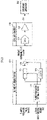
- a combination of a frequency response analyzer (FRA) 241 and a potentio/galvanostat (PGS) 242 is used, as illustrated in FIG. 7 .
- a sine wave signal of an arbitrary frequency is output from the oscillator constituting the FRA 241, and a current signal I(t) and a voltage signal V(t) of the secondary battery 240 corresponding to the sine wave signal are input from the PGS 242 to the FRA 241.
- the complex impedance Z(n0, n1, n2) of the secondary battery 240 is measured in the state of not being mounted on the electronic apparatus 200, such as immediately before the shipment of the secondary battery 240.
- the complex impedance Z(n0, n1, n2) of the secondary battery 240 in the state of being mounted on the electronic apparatus 200 may be measured.
- the FRA 241 may be configured by the control device 210
- the sensor group 206 may be configured by the PGS.
- the electronic apparatus 200 may be coupled to an external power supply such as a commercial power supply or the charger 400 for charging the secondary battery 240, and a sine wave signal may be output by the power supplied from an external power supply or the charger 400.
- FIG. 8 illustrates an example of a Nyquist plot illustrating the actual measurement result of the complex impedance Z(n0, n1, n2) of the secondary battery 240 together with the approximate curve of the plot.
- the horizontal axis is a real part ReZ of the complex impedance Z
- the vertical axis is an imaginary part -ImZ of the complex impedance Z.
- the radius of curvature of the substantially semicircular portion in the region of -ImZ > 0 is equivalent to the charge transfer resistance of the secondary battery 240.
- the radius of curvature tends to become smaller as the temperature T of the secondary battery 240 becomes higher.
- the influence of the Warburg impedance of the secondary battery 240 is reflected in the linear portion rising at about 45° in the low frequency region in the region of -ImZ > 0.
- the value of the parameter P(n0, n1, n2) of the secondary battery model is identified by the first control element 110 based on the measurement result of the complex impedance Z of the secondary battery 240 ( FIG. 6 /STEP 308).
- the parameter P(n0, n1, n2) defines the transfer function H of the calculator 121 (see FIG. 2 ).
- the secondary battery model is a model representing the voltage V(t) output from the secondary battery 240 when the current I(t) is input to the secondary battery 240.
- the secondary battery model is defined by a relational equation (01) by using the open circuit voltage OCV of the secondary battery 240 and the transfer function H(t) of the internal resistance.
- V t OCV t + H t * I t
- OCV(t) indicates that the open circuit voltage increases or decreases with charging and/or discharging of the current I(t).
- the transfer function H(z) of the equivalent circuit model of the internal resistance of the secondary battery is defined by a relational equation (02).
- the transfer function may be coupled in series instead of coupled in parallel.
- FIG. 9A illustrates an example of an equivalent circuit of the internal resistance of the secondary battery 240.
- the number of RC parallel circuits coupled in series was "3" in the embodiment illustrated in FIG. 9A , but may be smaller than 3 or larger than 3.
- the resistor Wo may be coupled in series with the resistor R in at least one RC parallel circuit.
- the capacitor C may be replaced with a constant phase element (CPE).
- a Warburg resistor W may be coupled in series with the resistor R of at least one RC parallel circuit (first RC parallel circuit in the example of FIG. 5B).
- the transfer function H i (z) of the i-th RC parallel circuit is defined by the relational equation (03) as the transfer function of an infinite impulse response (IIR) system.
- FIG. 10A illustrates a block diagram representing the transfer function H i (z) of the i-th RC parallel circuit.
- H i z b 0 + b i z ⁇ 1 / 1 + a i z ⁇ 1
- the transfer function Hw(z) of the resistor Wo equivalent to the Warburg impedance is defined by the relational equation (04) as the transfer function of a finite impulse response (FIR) system.
- FIG. 10B illustrates an example of a block diagram representing the transfer function Hw(z) of the resistor W0 equivalent to the Warburg impedance.
- H L (z) of the coil L is defined by the relational equation (05).
- H L z 2 L 0 / T 1 ⁇ z ⁇ 1 / 1 + z ⁇ 1
- the measured value of the open circuit voltage OCV(n0, n1, n2) identifies the value of the open circuit voltage OCV(t) output from the output device 123 in the secondary battery model (see the relational equation (01)). Then, depending on the value of the parameter, a secondary battery model is established for various types of secondary battery 240.
- the first index n1 is a predetermined number N1 or more ( FIG. 6 /STEP 310). If the determination result is negative ( FIG. 6 /STEP 310: NO), the value of the first index n1 is increased by "1" ( FIG. 6 /STEP 312), and then the processing after the temperature control of the secondary battery 240 is repeated ( FIG. 6 /STEP 304 ⁇ 306 ⁇ 308 ⁇ 310).
- a simulated battery control system as a second embodiment of the present invention illustrated in FIG. 11 includes a simulated battery control device 100, an electronic apparatus 200, and a charger 400.
- the simulated battery control device 100 and charger 400 are capable of communicating via a network to each other.
- the charger 400 includes a charger control device 420 and a simulated battery 230.
- the charger control device 420 includes a first charger control element 421, a second charger control element 422, and a third charger control element 423.
- Each of the first charger control element 421, the second charger control element 422, and the third charger control element 423 includes a processor (arithmetic processing unit), a memory (storage device), an I/O circuit, and the like.
- a memory or a storage device separate from the memory stores various data such as the simulated battery identifier ID(m0), the simulated battery temperature T(m1), the virtual deterioration degree D(m2), and the current command value Icmd(t) (see FIG. 3 /STEPS 214, 216, 218, and 220).
- Each of the first charger control element 421, the second charger control element 422, and the third charger control element 423 performs the same functions as the first apparatus control element 221, the second apparatus control element 222, and the third apparatus control element 223 of the electronic
- the charger 400 includes the simulated battery 230, the simulated battery 230 (see FIG. 1 ) is omitted in the electronic apparatus 200.
- the simulated battery control method of the secondary battery 240 mounted on the electronic apparatus 200 which is executed by the simulated battery control system of the second embodiment with the above configuration, will be described.
- the charger 400 mutual communicates with the simulated battery control device 100 instead of the electronic apparatus 200, and the operation of the simulated battery 230 is controlled by the same procedure as in the first embodiment (see FIGS. 3 to 4 ).
- the determination result on whether the first specified operation is performed by the first apparatus control element 221 is transmitted wirelessly or by wire from the electronic apparatus 200 to the charger 400, and the first charger control element 421 recognizes the determination result on whether the first specified operation is performed (see FIG. 3 /STEP 212).
- the voltage V(t) is input to the secondary battery 240 mounted on the electronic apparatus 200 wirelessly or by wire by using the simulated battery 230 by the first charger control element 421 (see FIG. 4 /STEP 224).
- the first apparatus control element 221 transmits the simulated battery identifier ID(m0), the simulated battery temperature T(m1), and the virtual deterioration degree D(m2) to the charger 400 wirelessly or by wire, and the first charger control element 421 recognizes the simulated battery identifier ID(m0), the simulated battery temperature T(m1), and the virtual deterioration degree D(m2) (see FIGS. 3 /STEPS 214, 216, and 218). Subsequently, the simulated battery identifier ID(m0), the simulated battery temperature T(m1), and the virtual deterioration degree D(m2) are transmitted from the charger 400 to the simulated battery control device 100 by the first charger control element 421 (see FIG. 3 /STEP 222).
- the second apparatus control element 222 transmits the current command value Icmd(t) to the charger 400 wirelessly or by wire, and the second charger control element 422 recognizes the current command value Icmd(t) (see FIG. 3 /STEP 220). Subsequently, the second charger control element 422 transmits the current command value Icmd(t) from the charger 400 to the simulated battery control device 100 (see FIG. 3 /STEP 222).
- the third charger control element 423 applies the voltage V(t) multiplied by the gain of the amplifier 232 in the simulated battery 230 to the specified load 250 of the electronic apparatus 200 coupled to the charger 400 based on the voltage command value Vcmd(t) (see FIG. 4 /STEP 224).
- the third charger control element 423 recognizes the operating characteristic OC(t) of the specified load 250 when the voltage V(t) is applied based on the communication with the electronic apparatus 200 (see FIG. 4 /STEP 226).
- the third charger control element 423 transmits the operating characteristic OC(t) of the specified load 250 to the simulated battery control device 100 (see FIG. 4 /STEP 228).
- the third apparatus control element 223 determines whether the second specified operation is performed through the input interface 202 (see FIG. 4 /STEP 230). Then, when it is determined that the second specified operation has been performed ( FIG. 4 /STEP 230: YES), the third charger control element 423 transmits an operating characteristic information request to the simulated battery control device 100 (see FIG. 4 /STEP 232).
- the operating characteristic information Info(OC(t)) is received by the third charger control element 423 and transmitted to the electronic apparatus 200 wirelessly or by wire, and the operating characteristic information Info(OC(t)) is output through the output interface 204 (see FIG. 4 /C22 ⁇ STEP 234).
- the function of the apparatus control unit 220 in the first embodiment may be shared by the electronic apparatus 200 and the charger control device 420 in the second embodiment.
- the simulated battery control information Info(D) may be received from the third apparatus control element 223 and output to the display device constituting the output interface 204 according to the determination result on whether the second specified operation is performed (see FIG. 3 /STEP 220 ⁇ STEP 222: YES ⁇ STEP 224).
- the third charger control element 423 may be omitted.
- the battery identifier ID may be transmitted to the simulated battery control device 100 by the second apparatus control element 222 (see FIG. 3 /STEP 220).
- the second charger control element 422 may be omitted.
- a secondary battery model is selected based on the temperature T of the secondary battery 240 or the electronic apparatus 200 during the measurement of the voltage response characteristic V(T), and the performance of the secondary battery 240 is evaluated, but as another embodiment, a secondary battery model may be selected based on the battery identifier ID representing the type of secondary battery 240 and the performance of the secondary battery 240 may be evaluated without considering the temperature T of the secondary battery 240 during the measurement of the voltage response characteristic V(T).
- the simulated battery control device 100 According to the simulated battery control device 100 according to the present invention and the simulated battery control method executed by the simulated battery control device 100, based on the communication between the electronic apparatus 200 and/or the charger 400 coupled to the electronic apparatus 200, and the simulated battery control device 100, the performance of the secondary battery 240 mounted in the electronic apparatus 200 is evaluated by the simulated battery control device 100. Then, the battery performance information Info(D) corresponding to the evaluation result is output to the output interface 204 of the electronic apparatus 200. Therefore, a user does not need to bring the electronic apparatus 200 or the secondary battery 240 to a specialized institution or the like, and the performance evaluation result of the secondary battery 240 can be grasped, and therefore the convenience for the user of the electronic apparatus 200 is improved.
- the estimation result of the deterioration degree of the secondary battery 240 may be recognized (see FIG. 3 /STEP 218).
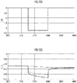
- the first apparatus control element 221 recognizes the measurement result of a voltage response characteristic V(n0, n2)(t) (to V(n0, n2)(z)) according to an impulse current I(t) of the secondary battery 240.
- the impulse current I(t) (to I(z)) is input to the secondary battery 240 by the first apparatus control element 221.
- the impulse current I(t) as illustrated in FIG. 12A is input to the secondary battery 240.
- the impulse current I(t) generated in the pulse current generator is input to the secondary battery 240.
- the pulse current generator may be mounted on the electronic apparatus 200 and a specified device mounted on the electronic apparatus 200 may be driven by the supply power from an external power supply or auxiliary power supply mounted on the electronic apparatus 200 to generate an impulse current.
- the voltage response characteristic V(n0, n2)(t) of the secondary battery 240 is measured by the first apparatus control element 221 based on the output signal of the voltage sensor constituting the sensor group 206. Thereby, for example, the voltage response characteristic V(n0, n2)(t) of the secondary battery 240 that changes as illustrated by the broken line in FIG. 12B is measured.
- FIG. 12B illustrates the measurement result of a voltage response characteristic V(n0,0)(t) of the secondary battery 240 when the second index n2 is 0 the solid line.
- the second index n2 is a predetermined number N2 or more. If the determination result is negative, the value of the first index n1 is reset to "0" and the value of the second index n2 is increased by "1". Then, the processing after the temperature control of the secondary battery 240 is repeated.
- the value of the parameter P(n0, n1, n2) of the secondary battery model is determined individually according to the difference in the deterioration degree D(n2) of the secondary battery 240 whose type identified by the battery identifier ID(n0) ( FIG. 6 /STEPS 308, 314, and 316), but as another embodiment, the value of the parameter P(n0, n1) of the secondary battery model may be determined without considering the difference in the deterioration degree D(n2) of the secondary battery 240.
- the value of the parameter P(n0,n1,n2) of the secondary battery model is determined individually according to the difference in the temperature T(nl) of the secondary battery 240 whose type is identified by the identifier ID(n0) ( FIG. 6 /STEPS 304, 314, and 316), but as another embodiment, the value of the parameter P(n0, n2) of the secondary battery model may be determined without considering the difference in the temperature T(nl) of the secondary battery 240.
- the simulated battery control device 100 According to the simulated battery control device 100 according to the present invention and the simulated battery control method executed by the simulated battery control device 100, based on the mutual communication between the electronic apparatus 200 and/or the charger 400 coupled to the electronic apparatus 200, and the simulated battery control device 100, the operation of the simulated battery 230 mounted on the electronic apparatus 200 is controlled, and the voltage V(t) corresponding to the current command value Icmd(t) is applied to the specified load 250. Then, the operating characteristic information Info (OC(t)) corresponding to the operating characteristic OC(t) of the specified load 250 corresponding to the applied voltage V(t) is output to the output interface 204 of the electronic apparatus 200.
- the operating characteristic information Info OC(t)
- the user does not need to bring the electronic apparatus 200 to a specialized institution or the like, and the operating characteristics OC(t) of the specified load 250 can be grasped when voltage V(t) corresponding to the current command value Icmd(t) is applied to the specified load 250 of the electronic apparatus 200, and therefore the convenience of the user of the electronic apparatus 200 can be improved.
- the parameter P(n0, n1, n2) of the secondary battery model at each of the different temperatures T(nl) is determined.
- the value of the parameter P(n0, n1, n2) of the secondary battery model is identified (see FIG. 6 /STEP 304 ⁇ 306 ⁇ 308, FIGS. 7 to 9 , and FIGS. 10A and 10B ).
- the impedance of the internal resistance of the secondary battery 240 is expressed by a transfer function representing each of the IIR system and the FIR system (see the relational equations (03) and (04), FIGS. 7 to 9 , and FIGS. 10A and 10B ).
- a secondary battery model having a parameter P(m,m1,m2) is selected based on the identifier ID(m), temperature T(m1), and deterioration degree D(m2) of the virtual secondary battery simulated by the simulated battery 230 (see FIG. 2 , FIG. 4 /STEP 214 ⁇ 216 ⁇ 218 ⁇ 110). Then, the voltage command value Vcmd(t), which is the output when the current command value Icmd(t) is input to the secondary battery model, is calculated, and the corresponding voltage V(t) is applied to the specified load 250 of the electronic apparatus 200 by the simulated battery 230 (see FIG. 3 /STEP 120, FIG. 4 /STEP 130 ⁇ 224, and FIG. 5 ). As a result, the reproduction accuracy of the characteristics of the secondary battery 240 by the simulated battery 230 can be improved under various conditions.
Landscapes
- Engineering & Computer Science (AREA)
- General Physics & Mathematics (AREA)
- Physics & Mathematics (AREA)
- General Chemical & Material Sciences (AREA)
- Manufacturing & Machinery (AREA)
- Chemical & Material Sciences (AREA)
- Chemical Kinetics & Catalysis (AREA)
- Electrochemistry (AREA)
- Power Engineering (AREA)
- Microelectronics & Electronic Packaging (AREA)
- Charge And Discharge Circuits For Batteries Or The Like (AREA)
- Secondary Cells (AREA)
- Tests Of Electric Status Of Batteries (AREA)
- Control Of Electric Motors In General (AREA)
- Testing Electric Properties And Detecting Electric Faults (AREA)
Applications Claiming Priority (2)
| Application Number | Priority Date | Filing Date | Title |
|---|---|---|---|
| JP2020007037A JP6944208B2 (ja) | 2020-01-20 | 2020-01-20 | 充電器 |
| PCT/JP2021/000133 WO2021149483A1 (ja) | 2020-01-20 | 2021-01-05 | 模擬電池制御装置、電子機器、充電器および模擬電池制御方法 |
Publications (2)
| Publication Number | Publication Date |
|---|---|
| EP4053962A1 true EP4053962A1 (de) | 2022-09-07 |
| EP4053962A4 EP4053962A4 (de) | 2024-01-03 |
Family
ID=76991824
Family Applications (1)
| Application Number | Title | Priority Date | Filing Date |
|---|---|---|---|
| EP21744697.0A Pending EP4053962A4 (de) | 2020-01-20 | 2021-01-05 | Steuervorrichtung für eine simulierte batterie, elektronisches gerät, ladegerät und simuliertes batteriesteuerungsverfahren |
Country Status (8)
| Country | Link |
|---|---|
| US (1) | US20220404427A1 (de) |
| EP (1) | EP4053962A4 (de) |
| JP (2) | JP6944208B2 (de) |
| KR (1) | KR102860654B1 (de) |
| CN (1) | CN115210591B (de) |
| CA (1) | CA3163913A1 (de) |
| TW (1) | TWI768652B (de) |
| WO (1) | WO2021149483A1 (de) |
Families Citing this family (4)
| Publication number | Priority date | Publication date | Assignee | Title |
|---|---|---|---|---|
| JP6944208B2 (ja) * | 2020-01-20 | 2021-10-06 | 東洋システム株式会社 | 充電器 |
| US12556021B2 (en) * | 2020-06-16 | 2026-02-17 | Black & Decker Inc. | System and method for charging a battery pack |
| WO2021257593A1 (en) | 2020-06-16 | 2021-12-23 | Black & Decker Inc. | Battery charger |
| JP7685455B2 (ja) * | 2022-03-09 | 2025-05-29 | 株式会社日立製作所 | 状態診断装置および状態診断システム |
Family Cites Families (41)
| Publication number | Priority date | Publication date | Assignee | Title |
|---|---|---|---|---|
| JPS5924617B2 (ja) | 1980-04-25 | 1984-06-11 | 古河電気工業株式会社 | 水中ケ−ブルの布設方法 |
| US6707273B1 (en) * | 2002-07-18 | 2004-03-16 | Electronic Design & Sales, Inc. | Temperature/voltage controlled battery charging circuit |
| US7542858B2 (en) * | 2005-06-03 | 2009-06-02 | Lsi Corporation | Simulated battery logic testing device |
| JP4692246B2 (ja) * | 2005-11-29 | 2011-06-01 | 日産自動車株式会社 | 二次電池の入出力可能電力推定装置 |
| JP4265629B2 (ja) * | 2006-08-01 | 2009-05-20 | トヨタ自動車株式会社 | 二次電池の充放電制御装置およびそれを搭載したハイブリッド車両 |
| JP4697105B2 (ja) * | 2006-09-21 | 2011-06-08 | 横河電機株式会社 | 電池特性模擬装置 |
| JP4703593B2 (ja) | 2007-03-23 | 2011-06-15 | 株式会社豊田中央研究所 | 二次電池の状態推定装置 |
| JP4943296B2 (ja) * | 2007-10-30 | 2012-05-30 | ソニー株式会社 | 電池パック、二次電池の充電方法、および充電装置 |
| JP5349250B2 (ja) * | 2008-12-01 | 2013-11-20 | カルソニックカンセイ株式会社 | 電池モデル同定方法 |
| JP2010203935A (ja) | 2009-03-04 | 2010-09-16 | Nissan Motor Co Ltd | 二次電池の入出力可能電力推定装置 |
| JP2010267570A (ja) * | 2009-05-18 | 2010-11-25 | Yokogawa Electric Corp | 特性解析装置 |
| JP2011038928A (ja) * | 2009-08-12 | 2011-02-24 | Yokogawa Electric Corp | 電池特性模擬装置 |
| JP2011122917A (ja) * | 2009-12-10 | 2011-06-23 | Yokogawa Electric Corp | 電池特性評価装置 |
| JP2011123033A (ja) * | 2009-12-14 | 2011-06-23 | Yokogawa Electric Corp | 電池特性評価装置 |
| JP2011158354A (ja) * | 2010-02-01 | 2011-08-18 | Sinfonia Technology Co Ltd | バッテリシミュレータ |
| EP2551687B1 (de) * | 2010-03-23 | 2020-07-15 | Furukawa Electric Co., Ltd. | Vorrichtung zur beurteilung des internen zustandes einer batterie und verfahren zur beurteilung des internen zustandes einer batterie |
| CN101908657A (zh) * | 2010-07-06 | 2010-12-08 | 奇瑞汽车股份有限公司 | 一种电池模拟系统 |
| JP2012019652A (ja) * | 2010-07-09 | 2012-01-26 | Sony Corp | 電力コントロール装置および電力コントロール方法 |
| JP5549449B2 (ja) * | 2010-07-20 | 2014-07-16 | 日産自動車株式会社 | 電池状態推定装置 |
| JP5549634B2 (ja) * | 2011-04-04 | 2014-07-16 | トヨタ自動車株式会社 | 二次電池の劣化判定方法とその装置 |
| CN103424582B (zh) * | 2012-05-17 | 2017-12-19 | 富泰华工业(深圳)有限公司 | 电池模拟电路 |
| JP2014063693A (ja) * | 2012-09-24 | 2014-04-10 | Toshiba Corp | 二次電池装置および電池容量推定システム |
| JP5810116B2 (ja) * | 2013-03-14 | 2015-11-11 | 古河電気工業株式会社 | 二次電池状態検出装置および二次電池状態検出方法 |
| US10345385B2 (en) * | 2014-05-12 | 2019-07-09 | Gm Global Technology Operations Llc. | Battery state estimation systems and methods using a nonlinear resistance element |
| DE102014226190A1 (de) * | 2014-12-17 | 2016-06-23 | Robert Bosch Gmbh | Testvorrichtung zur Überprüfung eines Batterie-Steuergerätes oder einer Batterie und Verfahren zur Testung eines Batterie-Steuergerätes oder einer Batterie |
| KR101927257B1 (ko) * | 2015-09-09 | 2018-12-10 | 주식회사 엘지화학 | 이차 전지의 못 관통 시험 장치 및 방법 |
| JP6414558B2 (ja) | 2016-02-01 | 2018-10-31 | 株式会社デンソー | 電池状態推定装置 |
| JP6647111B2 (ja) * | 2016-03-29 | 2020-02-14 | 古河電気工業株式会社 | 二次電池劣化推定装置および二次電池劣化推定方法 |
| CN107329088B (zh) * | 2016-04-29 | 2021-05-14 | 株式会社日立制作所 | 电池的健康状态诊断装置和方法 |
| KR20180006264A (ko) * | 2016-07-07 | 2018-01-17 | 주식회사 포스코아이씨티 | 배터리 모의 장치 및 배터리 모의 방법 |
| JP2018046667A (ja) * | 2016-09-14 | 2018-03-22 | 株式会社東芝 | 充電パターン作成装置、充電制御装置、充電パターン作成方法、プログラム、及び蓄電システム |
| CN108241125A (zh) * | 2016-12-23 | 2018-07-03 | 大唐移动通信设备有限公司 | 一种模拟电池 |
| US10677848B2 (en) * | 2017-06-02 | 2020-06-09 | Total S.A. | Apparatus, circuit model, and method for battery modelling |
| JP7038530B2 (ja) * | 2017-12-05 | 2022-03-18 | 昭和電工マテリアルズ株式会社 | デバイス状態検知装置、電源システムおよび自動車 |
| CA3095272C (en) * | 2018-03-28 | 2021-11-30 | Toyo System Co., Ltd. | Degradation state determination device and degradation state determination method |
| CN109143074B (zh) * | 2018-06-28 | 2020-10-30 | 中国科学院光电研究院 | 一种动力电池模型参数辨识方法及系统 |
| CN109375106A (zh) * | 2018-10-12 | 2019-02-22 | 江门市新会区古井源丰资产管理有限公司 | 一种电池的动态特性测试系统及方法 |
| US20210011979A1 (en) * | 2019-07-12 | 2021-01-14 | Apple Inc. | Battery Emulator with Controllable Frequency Response |
| JP6842213B1 (ja) * | 2019-12-27 | 2021-03-17 | 東洋システム株式会社 | 模擬電池構築方法および模擬電池構築装置 |
| JP6887700B1 (ja) * | 2020-01-20 | 2021-06-16 | 東洋システム株式会社 | 電池性能評価装置、電子機器、充電器および電池性能評価方法 |
| JP6944208B2 (ja) | 2020-01-20 | 2021-10-06 | 東洋システム株式会社 | 充電器 |
-
2020
- 2020-01-20 JP JP2020007037A patent/JP6944208B2/ja active Active
-
2021
- 2021-01-05 US US17/782,786 patent/US20220404427A1/en active Pending
- 2021-01-05 CA CA3163913A patent/CA3163913A1/en active Pending
- 2021-01-05 EP EP21744697.0A patent/EP4053962A4/de active Pending
- 2021-01-05 KR KR1020227020955A patent/KR102860654B1/ko active Active
- 2021-01-05 WO PCT/JP2021/000133 patent/WO2021149483A1/ja not_active Ceased
- 2021-01-05 CN CN202180010055.9A patent/CN115210591B/zh active Active
- 2021-01-13 TW TW110101221A patent/TWI768652B/zh active
- 2021-06-03 JP JP2021093573A patent/JP6997483B2/ja active Active
Also Published As
| Publication number | Publication date |
|---|---|
| US20220404427A1 (en) | 2022-12-22 |
| JP2021128172A (ja) | 2021-09-02 |
| TW202137045A (zh) | 2021-10-01 |
| TWI768652B (zh) | 2022-06-21 |
| EP4053962A4 (de) | 2024-01-03 |
| CN115210591B (zh) | 2025-09-12 |
| KR20220104213A (ko) | 2022-07-26 |
| KR102860654B1 (ko) | 2025-09-16 |
| JP6997483B2 (ja) | 2022-01-17 |
| CA3163913A1 (en) | 2021-07-29 |
| JP6944208B2 (ja) | 2021-10-06 |
| WO2021149483A1 (ja) | 2021-07-29 |
| CN115210591A (zh) | 2022-10-18 |
| JP2021113762A (ja) | 2021-08-05 |
Similar Documents
| Publication | Publication Date | Title |
|---|---|---|
| EP3896776B1 (de) | Verfahren und vorrichtung zur simulierten batteriekonstruktion | |
| EP4053962A1 (de) | Steuervorrichtung für eine simulierte batterie, elektronisches gerät, ladegerät und simuliertes batteriesteuerungsverfahren | |
| KR102648764B1 (ko) | 전지 성능 평가 방법 및 전지 성능 평가 장치 | |
| EP4318862A1 (de) | Vorrichtung zur beurteilung der batterieleistung und verfahren zur beurteilung der batterieleistung | |
| JP7090949B1 (ja) | 電池状態判定方法および電池状態判定装置 | |
| KR102696030B1 (ko) | 전지 성능 평가 장치, 전자기기, 충전기 및 전지 성능의 평가 방법 |
Legal Events
| Date | Code | Title | Description |
|---|---|---|---|
| STAA | Information on the status of an ep patent application or granted ep patent |
Free format text: STATUS: THE INTERNATIONAL PUBLICATION HAS BEEN MADE |
|
| PUAI | Public reference made under article 153(3) epc to a published international application that has entered the european phase |
Free format text: ORIGINAL CODE: 0009012 |
|
| STAA | Information on the status of an ep patent application or granted ep patent |
Free format text: STATUS: REQUEST FOR EXAMINATION WAS MADE |
|
| 17P | Request for examination filed |
Effective date: 20220601 |
|
| AK | Designated contracting states |
Kind code of ref document: A1 Designated state(s): AL AT BE BG CH CY CZ DE DK EE ES FI FR GB GR HR HU IE IS IT LI LT LU LV MC MK MT NL NO PL PT RO RS SE SI SK SM TR |
|
| DAV | Request for validation of the european patent (deleted) | ||
| DAX | Request for extension of the european patent (deleted) | ||
| A4 | Supplementary search report drawn up and despatched |
Effective date: 20231205 |
|
| RIC1 | Information provided on ipc code assigned before grant |
Ipc: H01M 10/44 20060101ALI20231129BHEP Ipc: H01M 10/052 20100101ALI20231129BHEP Ipc: G01R 31/392 20190101ALI20231129BHEP Ipc: G01R 31/389 20190101ALI20231129BHEP Ipc: G01R 31/367 20190101ALI20231129BHEP Ipc: H02J 7/00 20060101ALI20231129BHEP Ipc: H01M 10/48 20060101ALI20231129BHEP Ipc: H01M 10/42 20060101AFI20231129BHEP |
|
| STAA | Information on the status of an ep patent application or granted ep patent |
Free format text: STATUS: EXAMINATION IS IN PROGRESS |
|
| 17Q | First examination report despatched |
Effective date: 20260219 |