EP4056407B1 - Dispositif, procédé et système de transmission de contrôle de composants du système de transmission d'un véhicule - Google Patents
Dispositif, procédé et système de transmission de contrôle de composants du système de transmission d'un véhicule Download PDFInfo
- Publication number
- EP4056407B1 EP4056407B1 EP21465510.2A EP21465510A EP4056407B1 EP 4056407 B1 EP4056407 B1 EP 4056407B1 EP 21465510 A EP21465510 A EP 21465510A EP 4056407 B1 EP4056407 B1 EP 4056407B1
- Authority
- EP
- European Patent Office
- Prior art keywords
- electric
- windings
- internal combustion
- combustion engine
- electric machine
- Prior art date
- Legal status (The legal status is an assumption and is not a legal conclusion. Google has not performed a legal analysis and makes no representation as to the accuracy of the status listed.)
- Active
Links
Images

Classifications
-
- B—PERFORMING OPERATIONS; TRANSPORTING
- B60—VEHICLES IN GENERAL
- B60W—CONJOINT CONTROL OF VEHICLE SUB-UNITS OF DIFFERENT TYPE OR DIFFERENT FUNCTION; CONTROL SYSTEMS SPECIALLY ADAPTED FOR HYBRID VEHICLES; ROAD VEHICLE DRIVE CONTROL SYSTEMS FOR PURPOSES NOT RELATED TO THE CONTROL OF A PARTICULAR SUB-UNIT
- B60W20/00—Control systems specially adapted for hybrid vehicles
- B60W20/10—Controlling the power contribution of each of the prime movers to meet required power demand
- B60W20/13—Controlling the power contribution of each of the prime movers to meet required power demand in order to stay within battery power input or output limits; in order to prevent overcharging or battery depletion
-
- B—PERFORMING OPERATIONS; TRANSPORTING
- B60—VEHICLES IN GENERAL
- B60K—ARRANGEMENT OR MOUNTING OF PROPULSION UNITS OR OF TRANSMISSIONS IN VEHICLES; ARRANGEMENT OR MOUNTING OF PLURAL DIVERSE PRIME-MOVERS IN VEHICLES; AUXILIARY DRIVES FOR VEHICLES; INSTRUMENTATION OR DASHBOARDS FOR VEHICLES; ARRANGEMENTS IN CONNECTION WITH COOLING, AIR INTAKE, GAS EXHAUST OR FUEL SUPPLY OF PROPULSION UNITS IN VEHICLES
- B60K6/00—Arrangement or mounting of plural diverse prime-movers for mutual or common propulsion, e.g. hybrid propulsion systems comprising electric motors and internal combustion engines
- B60K6/20—Arrangement or mounting of plural diverse prime-movers for mutual or common propulsion, e.g. hybrid propulsion systems comprising electric motors and internal combustion engines the prime-movers consisting of electric motors and internal combustion engines, e.g. HEVs
- B60K6/42—Arrangement or mounting of plural diverse prime-movers for mutual or common propulsion, e.g. hybrid propulsion systems comprising electric motors and internal combustion engines the prime-movers consisting of electric motors and internal combustion engines, e.g. HEVs characterised by the architecture of the hybrid electric vehicle
- B60K6/48—Parallel type
-
- B—PERFORMING OPERATIONS; TRANSPORTING
- B60—VEHICLES IN GENERAL
- B60L—PROPULSION OF ELECTRICALLY-PROPELLED VEHICLES; SUPPLYING ELECTRIC POWER FOR AUXILIARY EQUIPMENT OF ELECTRICALLY-PROPELLED VEHICLES; ELECTRODYNAMIC BRAKE SYSTEMS FOR VEHICLES IN GENERAL; MAGNETIC SUSPENSION OR LEVITATION FOR VEHICLES; MONITORING OPERATING VARIABLES OF ELECTRICALLY-PROPELLED VEHICLES; ELECTRIC SAFETY DEVICES FOR ELECTRICALLY-PROPELLED VEHICLES
- B60L50/00—Electric propulsion with power supplied within the vehicle
- B60L50/50—Electric propulsion with power supplied within the vehicle using propulsion power supplied by batteries or fuel cells
-
- B—PERFORMING OPERATIONS; TRANSPORTING
- B60—VEHICLES IN GENERAL
- B60W—CONJOINT CONTROL OF VEHICLE SUB-UNITS OF DIFFERENT TYPE OR DIFFERENT FUNCTION; CONTROL SYSTEMS SPECIALLY ADAPTED FOR HYBRID VEHICLES; ROAD VEHICLE DRIVE CONTROL SYSTEMS FOR PURPOSES NOT RELATED TO THE CONTROL OF A PARTICULAR SUB-UNIT
- B60W20/00—Control systems specially adapted for hybrid vehicles
- B60W20/10—Controlling the power contribution of each of the prime movers to meet required power demand
- B60W20/15—Control strategies specially adapted for achieving a particular effect
- B60W20/16—Control strategies specially adapted for achieving a particular effect for reducing engine exhaust emissions
-
- B—PERFORMING OPERATIONS; TRANSPORTING
- B60—VEHICLES IN GENERAL
- B60K—ARRANGEMENT OR MOUNTING OF PROPULSION UNITS OR OF TRANSMISSIONS IN VEHICLES; ARRANGEMENT OR MOUNTING OF PLURAL DIVERSE PRIME-MOVERS IN VEHICLES; AUXILIARY DRIVES FOR VEHICLES; INSTRUMENTATION OR DASHBOARDS FOR VEHICLES; ARRANGEMENTS IN CONNECTION WITH COOLING, AIR INTAKE, GAS EXHAUST OR FUEL SUPPLY OF PROPULSION UNITS IN VEHICLES
- B60K6/00—Arrangement or mounting of plural diverse prime-movers for mutual or common propulsion, e.g. hybrid propulsion systems comprising electric motors and internal combustion engines
- B60K6/20—Arrangement or mounting of plural diverse prime-movers for mutual or common propulsion, e.g. hybrid propulsion systems comprising electric motors and internal combustion engines the prime-movers consisting of electric motors and internal combustion engines, e.g. HEVs
- B60K6/22—Arrangement or mounting of plural diverse prime-movers for mutual or common propulsion, e.g. hybrid propulsion systems comprising electric motors and internal combustion engines the prime-movers consisting of electric motors and internal combustion engines, e.g. HEVs characterised by apparatus, components or means specially adapted for HEVs
- B60K6/28—Arrangement or mounting of plural diverse prime-movers for mutual or common propulsion, e.g. hybrid propulsion systems comprising electric motors and internal combustion engines the prime-movers consisting of electric motors and internal combustion engines, e.g. HEVs characterised by apparatus, components or means specially adapted for HEVs characterised by the electric energy storing means, e.g. batteries or capacitors
-
- B—PERFORMING OPERATIONS; TRANSPORTING
- B60—VEHICLES IN GENERAL
- B60K—ARRANGEMENT OR MOUNTING OF PROPULSION UNITS OR OF TRANSMISSIONS IN VEHICLES; ARRANGEMENT OR MOUNTING OF PLURAL DIVERSE PRIME-MOVERS IN VEHICLES; AUXILIARY DRIVES FOR VEHICLES; INSTRUMENTATION OR DASHBOARDS FOR VEHICLES; ARRANGEMENTS IN CONNECTION WITH COOLING, AIR INTAKE, GAS EXHAUST OR FUEL SUPPLY OF PROPULSION UNITS IN VEHICLES
- B60K6/00—Arrangement or mounting of plural diverse prime-movers for mutual or common propulsion, e.g. hybrid propulsion systems comprising electric motors and internal combustion engines
- B60K6/20—Arrangement or mounting of plural diverse prime-movers for mutual or common propulsion, e.g. hybrid propulsion systems comprising electric motors and internal combustion engines the prime-movers consisting of electric motors and internal combustion engines, e.g. HEVs
- B60K6/22—Arrangement or mounting of plural diverse prime-movers for mutual or common propulsion, e.g. hybrid propulsion systems comprising electric motors and internal combustion engines the prime-movers consisting of electric motors and internal combustion engines, e.g. HEVs characterised by apparatus, components or means specially adapted for HEVs
- B60K6/38—Arrangement or mounting of plural diverse prime-movers for mutual or common propulsion, e.g. hybrid propulsion systems comprising electric motors and internal combustion engines the prime-movers consisting of electric motors and internal combustion engines, e.g. HEVs characterised by apparatus, components or means specially adapted for HEVs characterised by the driveline clutches
-
- B—PERFORMING OPERATIONS; TRANSPORTING
- B60—VEHICLES IN GENERAL
- B60W—CONJOINT CONTROL OF VEHICLE SUB-UNITS OF DIFFERENT TYPE OR DIFFERENT FUNCTION; CONTROL SYSTEMS SPECIALLY ADAPTED FOR HYBRID VEHICLES; ROAD VEHICLE DRIVE CONTROL SYSTEMS FOR PURPOSES NOT RELATED TO THE CONTROL OF A PARTICULAR SUB-UNIT
- B60W10/00—Conjoint control of vehicle sub-units of different type or different function
- B60W10/02—Conjoint control of vehicle sub-units of different type or different function including control of driveline clutches
-
- B—PERFORMING OPERATIONS; TRANSPORTING
- B60—VEHICLES IN GENERAL
- B60W—CONJOINT CONTROL OF VEHICLE SUB-UNITS OF DIFFERENT TYPE OR DIFFERENT FUNCTION; CONTROL SYSTEMS SPECIALLY ADAPTED FOR HYBRID VEHICLES; ROAD VEHICLE DRIVE CONTROL SYSTEMS FOR PURPOSES NOT RELATED TO THE CONTROL OF A PARTICULAR SUB-UNIT
- B60W10/00—Conjoint control of vehicle sub-units of different type or different function
- B60W10/04—Conjoint control of vehicle sub-units of different type or different function including control of propulsion units
- B60W10/06—Conjoint control of vehicle sub-units of different type or different function including control of propulsion units including control of combustion engines
-
- B—PERFORMING OPERATIONS; TRANSPORTING
- B60—VEHICLES IN GENERAL
- B60W—CONJOINT CONTROL OF VEHICLE SUB-UNITS OF DIFFERENT TYPE OR DIFFERENT FUNCTION; CONTROL SYSTEMS SPECIALLY ADAPTED FOR HYBRID VEHICLES; ROAD VEHICLE DRIVE CONTROL SYSTEMS FOR PURPOSES NOT RELATED TO THE CONTROL OF A PARTICULAR SUB-UNIT
- B60W10/00—Conjoint control of vehicle sub-units of different type or different function
- B60W10/04—Conjoint control of vehicle sub-units of different type or different function including control of propulsion units
- B60W10/08—Conjoint control of vehicle sub-units of different type or different function including control of propulsion units including control of electric propulsion units, e.g. motors or generators
-
- B—PERFORMING OPERATIONS; TRANSPORTING
- B60—VEHICLES IN GENERAL
- B60W—CONJOINT CONTROL OF VEHICLE SUB-UNITS OF DIFFERENT TYPE OR DIFFERENT FUNCTION; CONTROL SYSTEMS SPECIALLY ADAPTED FOR HYBRID VEHICLES; ROAD VEHICLE DRIVE CONTROL SYSTEMS FOR PURPOSES NOT RELATED TO THE CONTROL OF A PARTICULAR SUB-UNIT
- B60W10/00—Conjoint control of vehicle sub-units of different type or different function
- B60W10/24—Conjoint control of vehicle sub-units of different type or different function including control of energy storage means
- B60W10/26—Conjoint control of vehicle sub-units of different type or different function including control of energy storage means for electrical energy, e.g. batteries or capacitors
-
- B—PERFORMING OPERATIONS; TRANSPORTING
- B60—VEHICLES IN GENERAL
- B60W—CONJOINT CONTROL OF VEHICLE SUB-UNITS OF DIFFERENT TYPE OR DIFFERENT FUNCTION; CONTROL SYSTEMS SPECIALLY ADAPTED FOR HYBRID VEHICLES; ROAD VEHICLE DRIVE CONTROL SYSTEMS FOR PURPOSES NOT RELATED TO THE CONTROL OF A PARTICULAR SUB-UNIT
- B60W30/00—Purposes of road vehicle drive control systems not related to the control of a particular sub-unit, e.g. of systems using conjoint control of vehicle sub-units
- B60W30/18—Propelling the vehicle
- B60W30/192—Mitigating problems related to power-up or power-down of the driveline, e.g. start-up of a cold engine
-
- F—MECHANICAL ENGINEERING; LIGHTING; HEATING; WEAPONS; BLASTING
- F01—MACHINES OR ENGINES IN GENERAL; ENGINE PLANTS IN GENERAL; STEAM ENGINES
- F01N—GAS-FLOW SILENCERS OR EXHAUST APPARATUS FOR MACHINES OR ENGINES IN GENERAL; GAS-FLOW SILENCERS OR EXHAUST APPARATUS FOR INTERNAL-COMBUSTION ENGINES
- F01N3/00—Exhaust or silencing apparatus having means for purifying, rendering innocuous, or otherwise treating exhaust
- F01N3/08—Exhaust or silencing apparatus having means for purifying, rendering innocuous, or otherwise treating exhaust for rendering innocuous
- F01N3/10—Exhaust or silencing apparatus having means for purifying, rendering innocuous, or otherwise treating exhaust for rendering innocuous by thermal or catalytic conversion of noxious components of exhaust
- F01N3/18—Exhaust or silencing apparatus having means for purifying, rendering innocuous, or otherwise treating exhaust for rendering innocuous by thermal or catalytic conversion of noxious components of exhaust characterised by methods of operation; Control
- F01N3/20—Exhaust or silencing apparatus having means for purifying, rendering innocuous, or otherwise treating exhaust for rendering innocuous by thermal or catalytic conversion of noxious components of exhaust characterised by methods of operation; Control specially adapted for catalytic conversion
- F01N3/2006—Periodically heating or cooling catalytic reactors, e.g. at cold starting or overheating
- F01N3/2013—Periodically heating or cooling catalytic reactors, e.g. at cold starting or overheating using electric or magnetic heating means
-
- H—ELECTRICITY
- H02—GENERATION; CONVERSION OR DISTRIBUTION OF ELECTRIC POWER
- H02K—DYNAMO-ELECTRIC MACHINES
- H02K7/00—Arrangements for handling mechanical energy structurally associated with dynamo-electric machines, e.g. structural association with mechanical driving motors or auxiliary dynamo-electric machines
- H02K7/10—Structural association with clutches, brakes, gears, pulleys or mechanical starters
- H02K7/108—Structural association with clutches, brakes, gears, pulleys or mechanical starters with friction clutches
-
- H—ELECTRICITY
- H02—GENERATION; CONVERSION OR DISTRIBUTION OF ELECTRIC POWER
- H02M—APPARATUS FOR CONVERSION BETWEEN AC AND AC, BETWEEN AC AND DC, OR BETWEEN DC AND DC, AND FOR USE WITH MAINS OR SIMILAR POWER SUPPLY SYSTEMS; CONVERSION OF DC OR AC INPUT POWER INTO SURGE OUTPUT POWER; CONTROL OR REGULATION THEREOF
- H02M7/00—Conversion of AC power input into DC power output; Conversion of DC power input into AC power output
- H02M7/42—Conversion of DC power input into AC power output without possibility of reversal
- H02M7/44—Conversion of DC power input into AC power output without possibility of reversal by static converters
- H02M7/48—Conversion of DC power input into AC power output without possibility of reversal by static converters using discharge tubes with control electrode or semiconductor devices with control electrode
- H02M7/53—Conversion of DC power input into AC power output without possibility of reversal by static converters using discharge tubes with control electrode or semiconductor devices with control electrode using devices of a triode or transistor type requiring continuous application of a control signal
- H02M7/537—Conversion of DC power input into AC power output without possibility of reversal by static converters using discharge tubes with control electrode or semiconductor devices with control electrode using devices of a triode or transistor type requiring continuous application of a control signal using semiconductor devices only, e.g. single switched pulse inverters
-
- H—ELECTRICITY
- H02—GENERATION; CONVERSION OR DISTRIBUTION OF ELECTRIC POWER
- H02P—CONTROL OR REGULATION OF ELECTRIC MOTORS, ELECTRIC GENERATORS OR DYNAMO-ELECTRIC CONVERTERS; CONTROLLING TRANSFORMERS, REACTORS OR CHOKE COILS
- H02P25/00—Arrangements or methods for the control of AC motors characterised by the kind of AC motor or by structural details
- H02P25/16—Arrangements or methods for the control of AC motors characterised by the kind of AC motor or by structural details characterised by the circuit arrangement or by the kind of wiring
- H02P25/18—Arrangements or methods for the control of AC motors characterised by the kind of AC motor or by structural details characterised by the circuit arrangement or by the kind of wiring with arrangements for switching the windings, e.g. with mechanical switches or relays
-
- H—ELECTRICITY
- H02—GENERATION; CONVERSION OR DISTRIBUTION OF ELECTRIC POWER
- H02P—CONTROL OR REGULATION OF ELECTRIC MOTORS, ELECTRIC GENERATORS OR DYNAMO-ELECTRIC CONVERTERS; CONTROLLING TRANSFORMERS, REACTORS OR CHOKE COILS
- H02P27/00—Arrangements or methods for the control of AC motors characterised by the kind of supply voltage
- H02P27/04—Arrangements or methods for the control of AC motors characterised by the kind of supply voltage using variable-frequency supply voltage, e.g. inverter or converter supply voltage
- H02P27/06—Arrangements or methods for the control of AC motors characterised by the kind of supply voltage using variable-frequency supply voltage, e.g. inverter or converter supply voltage using DC to AC converters or inverters
- H02P27/08—Arrangements or methods for the control of AC motors characterised by the kind of supply voltage using variable-frequency supply voltage, e.g. inverter or converter supply voltage using DC to AC converters or inverters with pulse width modulation
-
- B—PERFORMING OPERATIONS; TRANSPORTING
- B60—VEHICLES IN GENERAL
- B60K—ARRANGEMENT OR MOUNTING OF PROPULSION UNITS OR OF TRANSMISSIONS IN VEHICLES; ARRANGEMENT OR MOUNTING OF PLURAL DIVERSE PRIME-MOVERS IN VEHICLES; AUXILIARY DRIVES FOR VEHICLES; INSTRUMENTATION OR DASHBOARDS FOR VEHICLES; ARRANGEMENTS IN CONNECTION WITH COOLING, AIR INTAKE, GAS EXHAUST OR FUEL SUPPLY OF PROPULSION UNITS IN VEHICLES
- B60K6/00—Arrangement or mounting of plural diverse prime-movers for mutual or common propulsion, e.g. hybrid propulsion systems comprising electric motors and internal combustion engines
- B60K6/20—Arrangement or mounting of plural diverse prime-movers for mutual or common propulsion, e.g. hybrid propulsion systems comprising electric motors and internal combustion engines the prime-movers consisting of electric motors and internal combustion engines, e.g. HEVs
- B60K6/22—Arrangement or mounting of plural diverse prime-movers for mutual or common propulsion, e.g. hybrid propulsion systems comprising electric motors and internal combustion engines the prime-movers consisting of electric motors and internal combustion engines, e.g. HEVs characterised by apparatus, components or means specially adapted for HEVs
- B60K6/26—Arrangement or mounting of plural diverse prime-movers for mutual or common propulsion, e.g. hybrid propulsion systems comprising electric motors and internal combustion engines the prime-movers consisting of electric motors and internal combustion engines, e.g. HEVs characterised by apparatus, components or means specially adapted for HEVs characterised by the motors or the generators
- B60K2006/268—Electric drive motor starts the engine, i.e. used as starter motor
-
- B—PERFORMING OPERATIONS; TRANSPORTING
- B60—VEHICLES IN GENERAL
- B60K—ARRANGEMENT OR MOUNTING OF PROPULSION UNITS OR OF TRANSMISSIONS IN VEHICLES; ARRANGEMENT OR MOUNTING OF PLURAL DIVERSE PRIME-MOVERS IN VEHICLES; AUXILIARY DRIVES FOR VEHICLES; INSTRUMENTATION OR DASHBOARDS FOR VEHICLES; ARRANGEMENTS IN CONNECTION WITH COOLING, AIR INTAKE, GAS EXHAUST OR FUEL SUPPLY OF PROPULSION UNITS IN VEHICLES
- B60K6/00—Arrangement or mounting of plural diverse prime-movers for mutual or common propulsion, e.g. hybrid propulsion systems comprising electric motors and internal combustion engines
- B60K6/20—Arrangement or mounting of plural diverse prime-movers for mutual or common propulsion, e.g. hybrid propulsion systems comprising electric motors and internal combustion engines the prime-movers consisting of electric motors and internal combustion engines, e.g. HEVs
- B60K6/22—Arrangement or mounting of plural diverse prime-movers for mutual or common propulsion, e.g. hybrid propulsion systems comprising electric motors and internal combustion engines the prime-movers consisting of electric motors and internal combustion engines, e.g. HEVs characterised by apparatus, components or means specially adapted for HEVs
- B60K6/26—Arrangement or mounting of plural diverse prime-movers for mutual or common propulsion, e.g. hybrid propulsion systems comprising electric motors and internal combustion engines the prime-movers consisting of electric motors and internal combustion engines, e.g. HEVs characterised by apparatus, components or means specially adapted for HEVs characterised by the motors or the generators
-
- B—PERFORMING OPERATIONS; TRANSPORTING
- B60—VEHICLES IN GENERAL
- B60K—ARRANGEMENT OR MOUNTING OF PROPULSION UNITS OR OF TRANSMISSIONS IN VEHICLES; ARRANGEMENT OR MOUNTING OF PLURAL DIVERSE PRIME-MOVERS IN VEHICLES; AUXILIARY DRIVES FOR VEHICLES; INSTRUMENTATION OR DASHBOARDS FOR VEHICLES; ARRANGEMENTS IN CONNECTION WITH COOLING, AIR INTAKE, GAS EXHAUST OR FUEL SUPPLY OF PROPULSION UNITS IN VEHICLES
- B60K6/00—Arrangement or mounting of plural diverse prime-movers for mutual or common propulsion, e.g. hybrid propulsion systems comprising electric motors and internal combustion engines
- B60K6/20—Arrangement or mounting of plural diverse prime-movers for mutual or common propulsion, e.g. hybrid propulsion systems comprising electric motors and internal combustion engines the prime-movers consisting of electric motors and internal combustion engines, e.g. HEVs
- B60K6/22—Arrangement or mounting of plural diverse prime-movers for mutual or common propulsion, e.g. hybrid propulsion systems comprising electric motors and internal combustion engines the prime-movers consisting of electric motors and internal combustion engines, e.g. HEVs characterised by apparatus, components or means specially adapted for HEVs
- B60K6/40—Arrangement or mounting of plural diverse prime-movers for mutual or common propulsion, e.g. hybrid propulsion systems comprising electric motors and internal combustion engines the prime-movers consisting of electric motors and internal combustion engines, e.g. HEVs characterised by apparatus, components or means specially adapted for HEVs characterised by the assembly or relative disposition of components
-
- B—PERFORMING OPERATIONS; TRANSPORTING
- B60—VEHICLES IN GENERAL
- B60W—CONJOINT CONTROL OF VEHICLE SUB-UNITS OF DIFFERENT TYPE OR DIFFERENT FUNCTION; CONTROL SYSTEMS SPECIALLY ADAPTED FOR HYBRID VEHICLES; ROAD VEHICLE DRIVE CONTROL SYSTEMS FOR PURPOSES NOT RELATED TO THE CONTROL OF A PARTICULAR SUB-UNIT
- B60W2710/00—Output or target parameters relating to a particular sub-units
- B60W2710/02—Clutches
- B60W2710/021—Clutch engagement state
-
- B—PERFORMING OPERATIONS; TRANSPORTING
- B60—VEHICLES IN GENERAL
- B60W—CONJOINT CONTROL OF VEHICLE SUB-UNITS OF DIFFERENT TYPE OR DIFFERENT FUNCTION; CONTROL SYSTEMS SPECIALLY ADAPTED FOR HYBRID VEHICLES; ROAD VEHICLE DRIVE CONTROL SYSTEMS FOR PURPOSES NOT RELATED TO THE CONTROL OF A PARTICULAR SUB-UNIT
- B60W2710/00—Output or target parameters relating to a particular sub-units
- B60W2710/06—Combustion engines, Gas turbines
- B60W2710/0694—Engine exhaust temperature
-
- B—PERFORMING OPERATIONS; TRANSPORTING
- B60—VEHICLES IN GENERAL
- B60W—CONJOINT CONTROL OF VEHICLE SUB-UNITS OF DIFFERENT TYPE OR DIFFERENT FUNCTION; CONTROL SYSTEMS SPECIALLY ADAPTED FOR HYBRID VEHICLES; ROAD VEHICLE DRIVE CONTROL SYSTEMS FOR PURPOSES NOT RELATED TO THE CONTROL OF A PARTICULAR SUB-UNIT
- B60W2710/00—Output or target parameters relating to a particular sub-units
- B60W2710/08—Electric propulsion units
-
- B—PERFORMING OPERATIONS; TRANSPORTING
- B60—VEHICLES IN GENERAL
- B60Y—INDEXING SCHEME RELATING TO ASPECTS CROSS-CUTTING VEHICLE TECHNOLOGY
- B60Y2200/00—Type of vehicle
- B60Y2200/90—Vehicles comprising electric prime movers
- B60Y2200/92—Hybrid vehicles
-
- B—PERFORMING OPERATIONS; TRANSPORTING
- B60—VEHICLES IN GENERAL
- B60Y—INDEXING SCHEME RELATING TO ASPECTS CROSS-CUTTING VEHICLE TECHNOLOGY
- B60Y2300/00—Purposes or special features of road vehicle drive control systems
- B60Y2300/91—Battery charging
-
- B—PERFORMING OPERATIONS; TRANSPORTING
- B60—VEHICLES IN GENERAL
- B60Y—INDEXING SCHEME RELATING TO ASPECTS CROSS-CUTTING VEHICLE TECHNOLOGY
- B60Y2400/00—Special features of vehicle units
- B60Y2400/60—Electric Machines, e.g. motors or generators
- B60Y2400/604—AC Machines, e.g. asynchronous motors
-
- B—PERFORMING OPERATIONS; TRANSPORTING
- B60—VEHICLES IN GENERAL
- B60Y—INDEXING SCHEME RELATING TO ASPECTS CROSS-CUTTING VEHICLE TECHNOLOGY
- B60Y2400/00—Special features of vehicle units
- B60Y2400/61—Arrangements of controllers for electric machines, e.g. inverters
-
- F—MECHANICAL ENGINEERING; LIGHTING; HEATING; WEAPONS; BLASTING
- F01—MACHINES OR ENGINES IN GENERAL; ENGINE PLANTS IN GENERAL; STEAM ENGINES
- F01N—GAS-FLOW SILENCERS OR EXHAUST APPARATUS FOR MACHINES OR ENGINES IN GENERAL; GAS-FLOW SILENCERS OR EXHAUST APPARATUS FOR INTERNAL-COMBUSTION ENGINES
- F01N2240/00—Combination or association of two or more different exhaust treating devices, or of at least one such device with an auxiliary device, not covered by indexing codes F01N2230/00 or F01N2250/00, one of the devices being
- F01N2240/16—Combination or association of two or more different exhaust treating devices, or of at least one such device with an auxiliary device, not covered by indexing codes F01N2230/00 or F01N2250/00, one of the devices being an electric heater, i.e. a resistance heater
-
- Y—GENERAL TAGGING OF NEW TECHNOLOGICAL DEVELOPMENTS; GENERAL TAGGING OF CROSS-SECTIONAL TECHNOLOGIES SPANNING OVER SEVERAL SECTIONS OF THE IPC; TECHNICAL SUBJECTS COVERED BY FORMER USPC CROSS-REFERENCE ART COLLECTIONS [XRACs] AND DIGESTS
- Y02—TECHNOLOGIES OR APPLICATIONS FOR MITIGATION OR ADAPTATION AGAINST CLIMATE CHANGE
- Y02T—CLIMATE CHANGE MITIGATION TECHNOLOGIES RELATED TO TRANSPORTATION
- Y02T10/00—Road transport of goods or passengers
- Y02T10/60—Other road transportation technologies with climate change mitigation effect
- Y02T10/62—Hybrid vehicles
Definitions
- the present invention relates to a control device according to the preamble of claim 1 and a controlling method according to the preamble of claim 6, for controlling components of a drivetrain system of a vehicle. Further, the invention relates to a drivetrain system for a vehicle.
- such a control device and such a control method are provided for vehicles having a hybrid drivetrain comprising an internal combustion engine and a multi-phase (e.g. three-phase) AC electric machine.
- a hybrid drivetrain comprising an internal combustion engine and a multi-phase (e.g. three-phase) AC electric machine.
- each of the internal combustion engine and the AC electric machine when operated can supply a contribution to a driving torque for driving the vehicle.
- control device is designed to provide
- the electrical power required to heat up the catalyst when starting the internal combustion engine is typically in the range of several kilowatts. Typically, the electrical power can be reduced a few minutes after the engine is started and then further reduced to zero, unless the vehicle is operated in a climatically cold region where it may be necessary to supply electrical power to heat the catalyst until the engine is switched off.
- One approach is to supply the heating resistance of the catalyst device in controlled manner with an electric current from a typically used 12V or 24V DC electrical system of the vehicle. This, however, requires relatively high electrical currents (approx. 100 A or more) to be supplied to the heating resistance which in turn requires a wiring to the heating resistance that demands a considerable volume of installation space and is expensive. In addition, the means required to control the electrical voltage and/or current to power the heatable catalyst device increases the cost.
- Another approach would be to provide a DC/DC converter for upconverting a voltage of the respective DC electrical system (e.g. 12V or 24V) for the supply of the heating resistance of the catalyst device. This, however, causes additional cost, weight and required volume of installation space due to the provision of the additional DC/DC converter.
- a DC/DC converter for upconverting a voltage of the respective DC electrical system (e.g. 12V or 24V) for the supply of the heating resistance of the catalyst device.
- US 5 321 231 A discloses an electrical system for supplying power to an electrical resistive heater that heats the catalyst of a catalytic converter.
- the electrical system includes an alternating current generator that has an output winding and a field winding that is carried by the rotor of the generator.
- the rotor is driven by an engine on a motor vehicle.
- the resistive catalyst heater is supplied with current by a circuit that includes a step-up transformer connected between the output winding of the generator and a bridge rectifier that feeds the heater.
- the system can be operated in a high power mode for supplying power to the heater, wherein the bridge rectifier is controlled as a function of the temperature of the catalyst and the output voltage can be pulse-width modulated.
- control device Starting from a control device according to the preamble of claim 1, the control device according to the invention is characterized
- an electrical power supply for the heating resistance of the electrically heatable catalyst device can be realized without remarkably increasing the cost, weight and installation space.
- the invention uses components that are available anyway in order to accomplish the electrical power supply for the heating resistance from the electric battery ("third operation mode") and/or from the AC electric machine coupled to the running internal combustion engine (“fourth operation mode”).
- the existing windings inside the electric machine are used to accomplish the functionality of a DC/DC converter for supplying electric energy to the heating resistance of the catalyst device.
- the converter comprises a plurality of half-bridges, each of the half-bridges electrically powered by the DC electrical system and formed by a series connection of two controllable semiconductor switches, wherein the control device is designed to effect a PWM control of the half-bridges in the first operation mode and the third operation mode, so that a respective output voltage for driving the respective electric current is provided at a circuit node between the two semiconductor switches, wherein the PWM control for each of the half-bridges is effected by a complementary switching on and off of the two respective semiconductor switches.
- the electric machine is a three-phase AC electric machine comprising three corresponding windings (e.g. stator windings), and the converter correspondingly comprises three half-bridges arranged in parallel to one another, wherein each of the half-bridges is electrically powered by a DC voltage provided by the DC electrical system and each of the half-bridges has a circuit node (between the two semiconductor switches), which is electrically connected with a respective one of the three windings.
- the converter correspondingly comprises three half-bridges arranged in parallel to one another, wherein each of the half-bridges is electrically powered by a DC voltage provided by the DC electrical system and each of the half-bridges has a circuit node (between the two semiconductor switches), which is electrically connected with a respective one of the three windings.
- the DC voltage provided by the DC electrical system is at least 12V and/or at the most 48V (e.g. 12V, 24V or 48V).
- controllable semiconductor switches are formed by transistors, in particular FETs.
- the windings of the AC electric machine are stator windings, in particular three stator windings, in particular connected in a star configuration.
- the windings are connected in a star configuration, meaning that each of the windings has a first terminal electrically connected to a common point (star point).
- the windings of the AC electric machine are connected in a star configuration, in which the star point (neutral point) is electrically connected with a first terminal of a switch of the second switch device, wherein a second terminal of that switch is electrically connected with a first terminal of the heating resistance.
- the second terminals of the windings each can be electrically supplied by a respective one of the plurality of output voltages of the converter.
- the second terminals of the windings each can be electrically connected to a circuit node of the respective half-bridge.
- ground potential the two electrical potentials creating the DC voltage provided by the DC electrical system (and corresponding to the battery voltage) are called “ground potential” and “supply potential”.
- one pole of the electric battery is permanently connected to a corresponding pole (e.g. "ground potential") of the DC electrical system, whereas the other pole of the battery can be connected/disconnected from/to the corresponding other pole (e.g. "supply potential") of the DC electrical system by means of the first switch device.
- the first switch device has only one switch for connecting/disconnecting the "supply potential” (e.g. positive pole of the battery) to/from the respective pole of the DC electrical system.
- the drivetrain system of the vehicle is a hybrid drivetrain system comprising the internal combustion engine and the AC electric machine, meaning that the vehicle is a hybrid vehicle and that both mentioned components can contribute to energy supply, e.g. torque supply in the drivetrain, for driving the vehicle.
- the vehicle is a hybrid vehicle, in particular a hybrid vehicle, in which a maximum power that can be supplied by the internal combustion engine is larger by a factor of at least 5, in particular at least 10, than a maximum power that can be supplied by the multi-phase AC electric machine.
- a capacitor is arranged at an electric path between the second switch device and the heating resistance of the catalyst device, in order to buffer a voltage applied at the heating resistance in the third operation mode and the fourth operation mode.
- this electric path is connecting the above mentioned second terminal of the switch of the second switch device with the first terminal of the heating resistance.
- the converter, the windings of the multi-phase AC electric machine, the second switch device, and the capacitor can advantageously implement the function of a "buck converter" for DC/DC conversion of the DC voltage of the DC electrical system to a heating supply voltage for supplying the heating resistance, which is used in the third operation mode, i.e. for electrically heating the catalyst device from the electric battery.
- the control device can be implemented as a software-controlled device (e.g. microcontroller), designed to accomplish the control used in the invention, or can be implemented as a functional part of such a software-controlled device (e.g. a vehicle's ECU for fulfilling also other functions)
- a software-controlled device e.g. microcontroller
- a functional part of such a software-controlled device e.g. a vehicle's ECU for fulfilling also other functions
- the above-mentioned object is solved by a method for controlling components of a drivetrain system of a vehicle.
- the controlling method according to the invention is characterized
- the converter when the first operation mode of the components for starting the internal combustion engine or supplying an additional torque is provided and thusly the first switch device connects the electric battery to the DC electrical system and the clutch couples the AC electric machine with the internal combustion engine, the converter causes electric current to flow from the DC electrical system in PWM fashion alternating to each one of the plurality of windings.
- the converter when the second operation mode of the components (for charging the electric battery by recuperation using the AC electric machine) is provided and thusly the internal combustion engine is running and the clutch couples the internal combustion engine with the AC electric machine and the first switch device connects the DC electrical system to the electric battery, the converter causes electric current to flow in synchronisation with the rotation of the AC electric machine alternating from each one of the plurality of windings to the DC electrical system.
- the converter in the third operation mode for electrically heating the catalyst device from the electric battery causes the electric current to flow from the DC electrical system in PWM fashion to the at least one winding or in PWM fashion to each one of the plurality of windings, respectively.
- the converter causes the electric current to flow from the DC electrical system in PWM fashion alternating to each one of the plurality of windings.
- each of the half-bridges electrically powered by the DC electrical system and formed by a series connection of two controllable semiconductor switches (e.g. transistors), in the following also referred to as "high-side switch” (connected to a supply potential of the DC system) and “low-side switch” (connected to a ground potential of the DC system), respectively, in the third operation mode the method can provide a PWM control of the half-bridges by a complementary switching on and off of the respective high-side and low-side switches.
- two controllable semiconductor switches e.g. transistors
- the converter, the windings of the AC electric machine and the second switching device (and optional the capacitor) can advantageously operate as a converter for supplying energy from the electrical battery to the EHC (electrically heated catalyst).
- one or more of the high-side switches each can be used for supplying a PWM voltage to the respective winding and therefore supplying an electric current flowing via the second switch device to the heating resistance of the EHC, wherein the corresponding low-side switches (e.g. low-side transistors) can be used for re-circulating the electric current ("simulating" a diode in a conventional buck DC/DC converter).
- all phases are alternatingly used in this way, such that the operation of each phase is shifted such that during a full switching cycle all phases are operated with equal durations.
- all high-side switches mentioned above can be used (one after another) for supplying a voltage (supply voltage of the electrical DC system) and thusly an electric current flowing through the respective winding and through the second switch device to the heating resistance.
- the respective low-side switch is switched on, such that the the electric current can re-circulate (to the ground potential of the electrical DC system).
- a variable voltage down-conversion can be achieved, for example, by a suitable variation of a PWM duty cycle (e.g. defined as the ratio between a PWM "ON"-time and a PWM period duration of the corresponding PWM signal).
- a PWM duty cycle e.g. defined as the ratio between a PWM "ON"-time and a PWM period duration of the corresponding PWM signal.
- the first switch device disconnects the electric battery from the DC electrical system. In this case, electrical power from the AC electric machine coupled to the running internal combustion engine in the fourth operation mode is only supplied to the heating resistance.
- the first switch device when in the fourth operation mode the first switch device connects the electric battery to the DC electrical system, electrical power from the AC electric machine in the fourth operation mode can be additionally supplied to the electric battery.
- a drivetrain system for a vehicle comprising
- control device and/or the controlling method according to the invention can be provided, individually or in any combination, also for the drivetrain system according to the invention.
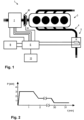
- Fig. 1 shows a hybrid drivetrain system 1 of a vehicle, comprising an AC electric machine 2 and an internal combustion engine 3.
- the AC electric machine 2 is a three-phase AC electric machine.
- the drivetrain system 1 further comprises a clutch 40 for coupling the AC electric machine 2 with the internal combustion engine 3 and for decoupling the AC electric machine 2 from the internal combustion engine 3, such that the AC electric machine 2 and the internal combustion engine 3 both can be operated to contribute to a driving torque for driving the vehicle.
- the clutch 40 is controlled by means of a corresponding clutch control signal "cc", which is generated by a control device 10 and transmitted through an electric system “E” (electric circuit arrangement) to the clutch 40.
- the drivetrain system 1 comprises a rechargeable electric battery "B" coupled to the electric system E, such that electric power can be transferred between the electric battery B and the AC electric machine 2 (in Fig. 1 through the electric system E).
- the system shown in Fig. 1 further comprises an electrically heatable catalyst (EHC) device 5 arranged in an exhaust passage 4 of the internal combustion engine 3.
- the catalyst device 5 comprises a heating resistance R, so that an electrical power for heating the catalyst device 5 can be provided by an electric current flowing through the resistance R.
- the catalyst device 5 is coupled to the electric system E, such that an electric power can be transferred from the electric system E to the resistance R for heating the catalyst device 5.
- Fig. 2 shows an example of the electrical power P used to heat an EHC, for example the the catalyst device 5 in Fig. 1 , dependent on time t.
- the electrical power P is raised up to a maximum value of approx. 3 kW right after starting the internal combustion engine 3. About 2 min later, the electrical power P is reduced to a medium value, and about 30 min later reduced to a minimum value of approx. 0.5 kW.
- the present invention relates to a particular design of the electric system E in connection with the control device 10 to provide an electrical power supply for the heating resistance R of the catalyst device, wherein problems of prior art solutions are avoided.
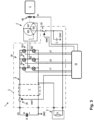
- Fig. 3 shows more detailed the drivetrain system 1 of Fig. 1 as designed according to an embodiment of the invention.
- the three-phase AC electric machine 2 has three stator windings W1, W2, W3 corresponding to the three phases of an AC driving of the electric machine 2 and arranged in star configuration, i.e. each of the windings W1, W2, W3 has a first terminal electrically connected to a common point ("star point"), whereas second terminals of the windings W1, W2, W3 are not connected to one another but individually with output nodes N1, N2, N3 of a converter 30 arranged in the electric system E.
- the rotor of the AC electric machine 2 is omitted in Fig. 3 .
- the converter 30 comprises three half-bridges 30-1, 30-2, 30-3, each of which is electrically powered by a supply voltage of a DC electrical system 6 ("electrical onboard network") between a ground potential "GND” and a supply potential "VS".
- Each of the half-bridges 30-1, 30-2, 30-3 is formed as a series connection of two transistors (generally: controllable semiconductor switches) as shown in Fig. 3 , in the following also referred to as "high-side switch” connected to the supply potential VS and "low-side switch” connected to the ground potential GND, respectively.
- the control device 10 is designed to enable and in case of particular operation modes of the drivetrain system 1 actually effect a complementary switching control of the half-bridges 30-1, 30-2, 30-3, meaning that the control device 10 generates converter control signals c1, c2, c3 transmitted (through the electric system E) to the respective half-bridges 30-1, 30-2, 30-3 such that in each of the half-bridges 30-1, 30-2, 30-3 the low-side switch is on and the corresponding high-side switch is off, or vice versa.
- each of the output potentials provided at the circuit nodes N1, N2, N3 of the half-bridges 30-1, 30-2, 30-3 can be switched between the ground potential GND and the supply potential VS, dependent on the corresponding converter control signal c1, c2, and c3, respectively. Therefore, by means of the control device 10, the respective output voltages provided at the circuit nodes N1, N2, N3 (related to the ground potential GND) can be switched between zero (ground potential GND) and the supply voltage (VS).
- the rechargeable electric battery B can be formed for example by a lithium-ion accumulator and in the shown example provides a battery voltage of 48V between the ground potential GND (negative potential of the battery B) and the supply potential VS (positive potential of the battery).
- the electric system E of the drivetrain system 1 further comprises a first switch device 20 by which the electric battery B can be connected to the DC electrical system 6 of the vehicle, and by which the electric battery B can be disconnected from the DC electrical system 6.
- the DC electrical system 6 constitutes an electrical onboard network for power supply of electrical consumers of the vehicle.
- the DC electrical system 6 is such an electrical onboard network for power supply of 48V consumers.
- the DC electrical system 6 can be equipped with a filter circuit F for reducing electrical disturbances in the electric overall system.
- the first switch device 20 is formed by a controllable switch for connecting/disconnecting a terminal (pole) providing the supply potential VS (positive potential) of the battery B to/from the electrical line providing the supply potential VS of the DC electrical system 6, whereas the ground potential GND (negative potential) of the battery B is permanently connected to an electrical line providing the ground potential GND of the DC electrical system 6.
- the first switch device 20 is controlled by means of a corresponding first switch control signal "csw1", which is generated by the control device 10 and transmitted (through the electric system E) to the first switch device 20.
- the drivetrain system 1 further comprises the above already mentioned converter 30, which is supplied by the supply voltage (e.g. 48V) of the DC electrical system 6 and which enables an electric current to flow from the DC electrical system 6 in alternating fashion, for example in PWM fashion, to each one of the plurality of windings W1, W2, W3 of the three-phase AC electric machine 2, for operating/driving the AC electric machine 2.
- the converter 30 further enables an electric current to flow in alternating fashion from each one of the windings W1, W2, W3 to the DC electrical system 6, for recovering electric energy from the AC electric machine 2.
- the control device 10 can be implemented for example as a software controlled device (e.g. microcontoller etc.) or as a functional part of a software controlled device used to accomplish additional functions in the vehicle (e.g. a vehicle's central ECU).
- the control device 10 serves in particular for controlling the first switch device 20 (by means of the signal csw1), the converter 30 (by means of the signals c1, c2, c3) and the clutch 40 (by means of the signal cc), wherein the control device 10 is designed to implement, according to respective current requirements, an operation of the drivetrain system 1 according to a plurality of different "operation modes".
- a first operation mode of the drivetrain system 1 can be initiated by the control device 10.
- This operation mode serves for starting the internal combustion engine 3 (in case that previously the internal combustion engine 3 was turned off) or supplying an additional torque (by means of the electric machine 2) in the drivetrain system (in case that the internal combustion engine 3 is already running), wherein electric energy from the electric battery B is used.
- the first switch device 20 connects the electric battery B to the DC electrical system 6, the converter 30 causes electric current to flow from the DC electrical system 6 in alternating fashion to each one of the plurality of windings W1, W2, W3 (e.g. PWM control), and the clutch 40 couples the AC electric machine 2 with the internal combustion engine 3.
- the converter 30 causes electric current to flow from the DC electrical system 6 in alternating fashion to each one of the plurality of windings W1, W2, W3 (e.g. PWM control)
- the clutch 40 couples the AC electric machine 2 with the internal combustion engine 3.
- the control device 10 effects a PWM control of the half-bridges 30-1, 30-2, 30-3, so that the respective output voltages for driving the electric currents are provided at the circuit nodes N1, N2, N3, wherein the PWM control for each of the half-bridges 30-1, 30-2, 30-3 is effected by a complementary switching on and off of the two respective high-side and low-side switches.
- a second operation mode of the drivetrain system 1 can be initiated by the control device 10.
- This operation mode serves for charging the electric battery B, wherein electric energy generated by the electric machine 2 in a "recuperation mode" is used.
- the clutch 40 couples the internal combustion engine 3 with the AC electric machine 2
- the converter 30 causes electric current to flow in alternating fashion from each one of the plurality of windings W1, W2, W3 to the DC electrical system 6, and the first switch device 20 connects the DC electrical system 6 to the electric battery B.
- the control device 10 or a device (e.g. vehicle's ECU) implementing the control device 10 can take into account measured momentary values of rotational position and/or rotational speed of the rotor of the AC electric machine 2 and/or electric current flowing through the windings W1, W2, W3.
- a peculiar feature of the drivetrain system 1 according to the example of Fig. 3 is a second switch device 50 for (at least intermittendly) connecting the star point of the windings W1, W2, W3 of the AC electric machine 2 to a first terminal of the heating resistance R of the catalyst device 5, and disconnecting the star point from the heating resistance R, respectively.
- the second switch device 50 is formed by a switch having a first terminal connected to the star point and a second terminal connected to the first terminal of the heating resistance R.
- a second terminal of the heating resistance R is permanently connected to the ground potential GND.
- the second switch device 50 is controlled by means of a corresponding second switch control signal "csw2", which is generated by the control device 10 and transmitted (through the electric system E) to the second switch device 50.
- control device 10 is further designed to implement, according to respective current requirements, an operation of the drivetrain system 1 according to at least one of the third and fourth operation modes described below.
- control device 10 further serves in particular for controlling the second switch device 50 by means of the above-mentioned signal csw2.
- a third operation mode of the drivetrain system 1 can be initiated by the control device 10. This operation mode serves for electrically heating the catalyst device 5, wherein electric energy from the electric battery B is used.
- the clutch 50 decouples the AC electric machine 2 from the internal combustion engine 3, the first switch device 20 connects the electric battery B to the DC electrical system 6, the converter 30 causes electric current to flow from the DC electrical system 6 in alternating fashion to each one of the plurality of windings W1, W2, W3, wherein the second switch device 50 is used to (at least intermittendly) connect the respective winding W1, W2, W3 (in the shown example via the star point of the winding arrangement) to the first terminal of the heating resistance R of the catalyst device 5 (whereas the second terminal of the heating resistance R is permanently connected to the ground potential GND).
- a capacitor C is arranged at an electrical line between the second terminal of the switch of the second switch device 50 and the first terminal of the heating resistance R of the catalyst device 5, in order to buffer a voltage applied at the heating resistance R in the third operation mode (as well as in the fourth operation mode explained below).
- the electrical circuit comprising the converter 30, the electric machine 2, the second switch device 50 and the capacitor C can operate like a (conventional) multi-phase buck converter to supply energy to the catalyst device 5.
- the high-side switches can be used for supplying a PWM voltage (VS) for a certain time ("ON"-time in PWM voltage) to the corresponding one of the windings W1, W2, W3, and the low-side switches can be used for re-circulating the corresponding electrical current (simulating the diode in a conventional Buck converter).
- the switch of the second switch device 50 is turned on (closed) for the whole duration of the third operation mode.
- a period time T which can be chosen corresponding to a PWM frequency (1/T) for example in the range of some kHz.
- the respective "ON"-times of the signals c1, c2, c3 are chosen to be equal.
- a variable voltage down-conversion can be achieved e.g. by a corresponding variation of the PWM duty cycle (e.g. defined as the ratio between the PWM "ON"-time and a PWM period of the signals c1, c2, c3).
- a fourth operation mode of the drivetrain system 1 can be initiated by the control device 10.
- This operation mode serves for electrically heating the catalyst device 5, wherein electric energy generated by the electric machine 2 in a "recuperation mode" is used.
- the clutch 40 couples the internal combustion engine 3 with the AC electric machine 2
- the converter 30 causes electric current to flow in alternating fashion from each one of the plurality of windings W1, W2, W3 via the second switch device 50 to the heating resistance R of the catalyst device 5, wherein the second switch device 50 (at least intermittendly) connects the respective winding (via the star point of the winding arrangement) to the first terminal of the heating resistance R of the catalyst device 5 (whereas the second terminal of the heating resistance R is permanently connected to the ground potential GND).
- the second switch device 50 is permanently turned off, i.e. the switch disconnects the windings W1, W2, W3 (here: the star point) from the electrical line leading to the first terminal of the heating resistance R.
- the electrical circuit comprising the converter 30, the electric machine 2, the second switch device 50 and the capacitor C can also operate like a multi-phase buck converter to supply energy to the catalyst device 5.
- the electric energy is transferred not from the electric battery B, but from the windings of the AC electric machine 2 which is coupled to and driven by the internal combustion engine 3 (recuperation mode).
- the switch of the second switch device 50 is turned on (closed) for the whole duration of the fourth operation mode, but the low-side switches of the converter 30 are operated alternatingly and synchronized with the rotation of the electric machine 2, such that a voltage generated in each of the windings W1, W2, W3 is applied to the heating resistance R of the catalyst device 5.
- control device 10 can take into account e.g. measured momentary values of the rotational position of the rotor of the AC electric machine 2.
- a variation of the power actually supplied to the EHC can be achieved within the framework of the invention by a suitable variation of the time dependent control of the converter.
- a time dependent switching ON ond OFF of the second switch device and e.g. a variation thereof) can be foreseen to this end.
- an embodiment of the invention relates to a control device (10) for controlling components (20, 30, 40, 50) of a drivetrain system (1) of a vehicle, said components (20, 30, 40, 50) comprising a first switch device (20) for connecting/disconnecting an electric battery (B) with a DC electrical system (6); a converter (30) for enabling electric current to flow from the system (6) to each one of windings (W1, W2, W3) of a multi-phase AC electric machine (2), for driving the electric machine (2), and enabling electric current to flow from each one of the windings (W1, W2, W3) to the system (6), for recovering electric energy from the electric machine (2), respectively; a clutch (40) for coupling/decoupling the electric machine (2) with an internal combustion engine (3).
- the control device (10) provides a first operation mode, in which the first switch device (20) connects the electric battery (B) to the system (6), the converter (30) causes current to flow from the system (6) to each one of the windings (W1, W2, W3), and the clutch (40) couples the electric machine (2) with the engine (3), e.g. for starting the engine (3), and/or a second operation mode, in which the engine (3) is running, the clutch (40) couples the engine (3) with the electric machine (2), the converter (30) causes current to flow from each one of the windings (W1, W2, W3) to the system (6), and the first switch device (20) connects the system (6) to the electric battery (B), for charging the electric battery (B).
- the components (20, 30, 40, 50) further comprise a second switch device (50) for connecting/disconnecting at least one of the windings (W1, W2, W3) of the electric machine (2) with a heating resistance (R) of an electrically heatable catalyst device (5) of the engine (3), wherein the control device (10) further provides a third operation mode, in which the clutch (40) decouples the electric machine (2) from the engine (3), the first switch device (20) connects the electric battery (B) to the system (6), the converter (30) causes current to flow from the system (6) to the at least one winding (W1, W2, W3) and the second switch device (50) connects the respective winding (W1, W2, W3) to the heating resistance (R), for electrically heating the catalyst device (5), and/or a fourth operation mode, in which the engine (3) is running, the clutch (40) couples the engine (3) with the electric machine (2), the converter (30) causes current to flow from each of the windings (W1, W2, W3) via the second switch device (50)
Landscapes
- Engineering & Computer Science (AREA)
- Chemical & Material Sciences (AREA)
- Mechanical Engineering (AREA)
- Combustion & Propulsion (AREA)
- Transportation (AREA)
- Power Engineering (AREA)
- Chemical Kinetics & Catalysis (AREA)
- Automation & Control Theory (AREA)
- Health & Medical Sciences (AREA)
- Toxicology (AREA)
- General Engineering & Computer Science (AREA)
- Life Sciences & Earth Sciences (AREA)
- Sustainable Development (AREA)
- Sustainable Energy (AREA)
- Electric Propulsion And Braking For Vehicles (AREA)
- Exhaust Gas After Treatment (AREA)
- Control Of Vehicle Engines Or Engines For Specific Uses (AREA)
Claims (9)
- Dispositif de commande (10) pour commander des composants (20, 30, 40, 50) d'un système de chaîne de traction (1) d'un véhicule, lesdits composants (20, 30, 40, 50) comprenant- un premier dispositif interrupteur (20) pour respectivement connecter une batterie électrique (B) du véhicule à un système électrique à courant continu (6) du véhicule, et déconnecter la batterie électrique (B) du système électrique à courant continu (6),- un convertisseur bidirectionnel (30) pour respectivement permettre à un courant électrique de circuler depuis le système électrique à courant continu (6) de manière alternée, par exemple en mode PWM, vers chacun d'une pluralité d'enroulements (W1, W2, W3) d'une machine électrique à courant alternatif polyphasée (2) du véhicule, dans le but d'entraîner la machine électrique à courant alternatif (2), et permettre à un courant électrique de circuler de manière alternée depuis chacun de la pluralité d'enroulements (W1, W2, W3) vers le système électrique à courant continu (6), dans le but de récupérer de l'énergie électrique de la machine électrique à courant alternatif (2),- un embrayage (40) pour respectivement accoupler la machine électrique à courant alternatif (2) avec un moteur à combustion interne (3) du véhicule, et désaccoupler la machine électrique à courant alternatif (2) du moteur à combustion interne (3),
le dispositif de commande (10) étant conçu pour fournir- un premier mode de fonctionnement des composants (20, 30, 40, 50), dans lequel le premier dispositif interrupteur (20) connecte la batterie électrique (B) au système électrique à courant continu (6), le convertisseur (30) fait circuler un courant électrique depuis le système électrique à courant continu (6) de manière alternée vers chacun de la pluralité d'enroulements (W1, W2, W3), et l'embrayage (40) accouple la machine électrique à courant alternatif (2) avec le moteur à combustion interne (3), dans le but de démarrer le moteur à combustion interne (3) ou dans le but de fournir un couple supplémentaire dans le système de chaîne de traction (1), et/ou- un deuxième mode de fonctionnement des composants (20, 30, 40, 50), dans lequel le moteur à combustion interne (3) tourne, l'embrayage (40) accouple le moteur à combustion interne (3) avec la machine électrique à courant alternatif (2), le convertisseur (30) fait circuler un courant électrique de manière alternée depuis chacun de la pluralité d'enroulements (W1, W2, W3) vers le système électrique à courant continu (6), et le premier dispositif interrupteur (20) connecte le système électrique à courant continu (6) à la batterie électrique (B), dans le but de charger la batterie électrique (B), caractérisé en ce que les composants (20, 30, 40, 50) comprennent en outre- un deuxième dispositif interrupteur (50) pour respectivement connecter au moins un des enroulements (W1, W2, W3) de la machine électrique à courant alternatif (2) à une résistance chauffante (R) d'un dispositif catalyseur chauffable électriquement (5) dans un passage d'échappement (4) du moteur à combustion interne (3), et déconnecter l'au moins un des enroulements (W1, W2, W3) de la résistance chauffante (R),
et en ce que le dispositif de commande (10) est conçu en outre pour fournir- un troisième mode de fonctionnement des composants (20, 30, 40, 50), dans lequel l'embrayage (40) désaccouple la machine électrique à courant alternatif (2) du moteur à combustion interne (3), le premier dispositif interrupteur (20) connecte la batterie électrique (B) au système électrique à courant continu (6), le convertisseur (30) fait circuler un courant électrique depuis le système électrique à courant continu (6) vers l'au moins un enroulement (W1, W2, W3) ou de manière alternée vers chacun de la pluralité d'enroulements (W1, W2, W3), le deuxième dispositif interrupteur (50) connectant l'enroulement (W1, W2, W3) respectif à la résistance chauffante (R) du dispositif catalyseur (5), dans le but de chauffer électriquement le dispositif catalyseur (5), et/ou- un quatrième mode de fonctionnement des composants (20, 30, 40, 50), dans lequel le moteur à combustion interne (3) tourne, l'embrayage (40) accouple le moteur à combustion interne (3) avec la machine électrique à courant alternatif (2), le convertisseur (30) fait circuler un courant électrique de manière alternée depuis chacun de la pluralité d'enroulements (W1, W2, W3) via le deuxième dispositif interrupteur (50) vers la résistance chauffante (R) du dispositif catalyseur (5), le deuxième dispositif interrupteur (50) connectant l'enroulement (W1, W2, W3) respectif à la résistance chauffante (R) dans le but de chauffer électriquement le dispositif catalyseur (5). - Dispositif de commande (10) selon la revendication 1, le convertisseur (30) comprenant une pluralité de demi-ponts (30-1, 30-2, 30-3), chacun des demi-ponts (30-1, 30-2, 30-3) étant alimenté électriquement par le système électrique à courant continu (6) et étant formé par un branchement en série de deux interrupteurs à semi-conducteur commandables, le dispositif de commande (10) étant conçu pour effectuer une commande PWM des demi-ponts (30-1, 30-2, 30-3) dans le premier mode de fonctionnement et le troisième mode de fonctionnement, de sorte qu'une tension de sortie respective pour piloter le courant électrique respectif est fournie au niveau d'un nœud de circuit (N1, N2, N3) entre les deux interrupteurs à semi-conducteur, la commande PWM pour chacun des demi-ponts (30-1, 30-2, 30-3) s'effectuant par une fermeture et une ouverture complémentaires des deux interrupteurs à semi-conducteur respectifs.
- Dispositif de commande (10) selon la revendication 1 ou 2, les enroulements (W1, W2, W3) de la machine électrique à courant alternatif (2) étant des enroulements statoriques (W1, W2, W3), en particulier trois enroulements statoriques (W1, W2, W3) branchés en étoile.
- Dispositif de commande (10) selon l'une quelconque des revendications précédentes, le système de chaîne de traction (1) du véhicule étant un système de chaîne de traction hybride (1) comprenant le moteur à combustion interne (3) et la machine électrique à courant alternatif (2).
- Dispositif de commande (10) selon l'une quelconque des revendications précédentes, un condensateur (C) étant agencé au niveau d'un chemin électrique entre le deuxième dispositif interrupteur (50) et la résistance chauffante (R) du dispositif catalyseur (5), afin de tamponner une tension appliquée au niveau de la résistance chauffante (R) dans le troisième mode de fonctionnement et le quatrième mode de fonctionnement.
- Procédé de commande de composants (20, 30, 40, 50) d'un système de chaîne de traction (1) d'un véhicule, lesdits composants (20, 30, 40, 50) comprenant- un premier dispositif interrupteur (20) pour respectivement connecter une batterie électrique (B) du véhicule à un système électrique à courant continu (6) du véhicule, et déconnecter la batterie électrique (B) du système électrique à courant continu (6),- un convertisseur bidirectionnel (30) pour respectivement permettre à un courant électrique de circuler depuis le système électrique à courant continu (6) de manière alternée, et par exemple en mode PWM, vers chacun d'une pluralité d'enroulements (W1, W2, W3) d'une machine électrique à courant alternatif polyphasée (2) du véhicule, dans le but d'entraîner la machine électrique à courant alternatif (2), et permettre à un courant électrique de circuler de manière alternée depuis chacun de la pluralité d'enroulements (W1, W2, W3) vers le système électrique à courant continu (6), dans le but de récupérer de l'énergie électrique de la machine électrique à courant alternatif (2),- un embrayage (40) pour respectivement accoupler la machine électrique à courant alternatif (2) avec un moteur à combustion interne (3) du véhicule, et désaccoupler la machine électrique à courant alternatif (2) du moteur à combustion interne (3),
le procédé étant conçu pour fournir- un premier mode de fonctionnement des composants (20, 30, 40, 50), dans lequel le premier dispositif interrupteur (20) connecte la batterie électrique (B) au système électrique à courant continu (6), le convertisseur (30) fait circuler un courant électrique depuis le système électrique à courant continu (6) de manière alternée vers chacun de la pluralité d'enroulements (W1, W2, W3), et l'embrayage (40) accouple la machine électrique à courant alternatif (2) avec le moteur à combustion interne (3), dans le but de démarrer le moteur à combustion interne (3) ou dans le but de fournir un couple supplémentaire dans le système de chaîne de traction (1), et/ou- un deuxième mode de fonctionnement des composants (20, 30, 40, 50), dans lequel le moteur à combustion interne (3) tourne, l'embrayage (40) accouple le moteur à combustion interne (3) avec la machine électrique à courant alternatif (2), le convertisseur (30) fait circuler un courant électrique de manière alternée depuis chacun de la pluralité d'enroulements (W1, W2, W3) vers le système électrique à courant continu (6), et le premier dispositif interrupteur (20) connecte le système électrique à courant continu (6) à la batterie électrique (B), dans le but de charger la batterie électrique (B), caractérisé en ce que les composants (20, 30, 40, 50) comprennent en outre- un deuxième dispositif interrupteur (50) pour respectivement connecter au moins un des enroulements (W1, W2, W3) de la machine électrique à courant alternatif (2) à une résistance chauffante (R) d'un dispositif catalyseur chauffable électriquement (5) dans un passage d'échappement (4) du moteur à combustion interne (3), et déconnecter l'au moins un des enroulements (W1, W2, W3) de la résistance chauffante (R),
et en ce que le procédé est conçu en outre pour fournir- un troisième mode de fonctionnement des composants (20, 30, 40, 50), dans lequel l'embrayage (40) désaccouple la machine électrique à courant alternatif (2) du moteur à combustion interne (3), le premier dispositif interrupteur (20) connecte la batterie électrique (B) au système électrique à courant continu (6), le convertisseur (30) fait circuler un courant électrique depuis le système électrique à courant continu (6) vers l'au moins un enroulement (W1, W2, W3) ou de manière alternée vers chacun de la pluralité d'enroulements (W1, W2, W3), le deuxième dispositif interrupteur (50) connectant l'enroulement (W1, W2, W3) respectif à la résistance chauffante (R) du dispositif catalyseur (5), dans le but de chauffer électriquement le dispositif catalyseur (5), et/ou- un quatrième mode de fonctionnement des composants (20, 30, 40, 50), dans lequel le moteur à combustion interne (3) tourne, l'embrayage (40) accouple le moteur à combustion interne (3) avec la machine électrique à courant alternatif (2), le convertisseur (30) fait circuler un courant électrique de manière alternée depuis chacun de la pluralité d'enroulements (W1, W2, W3) via le deuxième dispositif interrupteur (50) vers la résistance chauffante (R) du dispositif catalyseur (5), le deuxième dispositif interrupteur (50) connectant l'enroulement (W1, W2, W3) respectif à la résistance chauffante (R) dans le but de chauffer électriquement le dispositif catalyseur (5). - Procédé selon l'une quelconque des revendications précédentes, dans le troisième mode de fonctionnement, le convertisseur (30) faisant circuler le courant électrique depuis le système électrique à courant continu (6) respectivement en mode PWM vers l'au moins un enroulement (W1, W2, W3) ou en mode PWM vers chacun de la pluralité d'enroulements (W1, W2, W3).
- Procédé selon l'une quelconque des revendications précédentes, dans le quatrième mode de fonctionnement, le premier dispositif interrupteur (20) déconnectant la batterie électrique (B) du système électrique à courant continu (6).
- Système de chaîne de traction (1) pour un véhicule, comprenant les composants et un dispositif de commande pour commander les composants selon la revendication 1.
Priority Applications (4)
| Application Number | Priority Date | Filing Date | Title |
|---|---|---|---|
| EP21465510.2A EP4056407B1 (fr) | 2021-03-12 | 2021-03-12 | Dispositif, procédé et système de transmission de contrôle de composants du système de transmission d'un véhicule |
| KR1020220029693A KR102693580B1 (ko) | 2021-03-12 | 2022-03-08 | 차량의 구동 트레인 시스템의 구성요소를 제어하기 위한 제어 디바이스 및 방법 |
| US17/691,664 US12358492B2 (en) | 2021-03-12 | 2022-03-10 | Control device and a method for controlling components of a drivetrain system of a vehicle |
| CN202210237013.5A CN115071675B (zh) | 2021-03-12 | 2022-03-11 | 用于控制车辆的动力传动系统的部件的方法和控制装置 |
Applications Claiming Priority (1)
| Application Number | Priority Date | Filing Date | Title |
|---|---|---|---|
| EP21465510.2A EP4056407B1 (fr) | 2021-03-12 | 2021-03-12 | Dispositif, procédé et système de transmission de contrôle de composants du système de transmission d'un véhicule |
Publications (2)
| Publication Number | Publication Date |
|---|---|
| EP4056407A1 EP4056407A1 (fr) | 2022-09-14 |
| EP4056407B1 true EP4056407B1 (fr) | 2025-05-07 |
Family
ID=75339661
Family Applications (1)
| Application Number | Title | Priority Date | Filing Date |
|---|---|---|---|
| EP21465510.2A Active EP4056407B1 (fr) | 2021-03-12 | 2021-03-12 | Dispositif, procédé et système de transmission de contrôle de composants du système de transmission d'un véhicule |
Country Status (4)
| Country | Link |
|---|---|
| US (1) | US12358492B2 (fr) |
| EP (1) | EP4056407B1 (fr) |
| KR (1) | KR102693580B1 (fr) |
| CN (1) | CN115071675B (fr) |
Families Citing this family (2)
| Publication number | Priority date | Publication date | Assignee | Title |
|---|---|---|---|---|
| US11739671B2 (en) * | 2021-04-28 | 2023-08-29 | Ford Global Technologies, Llc | Systems and methods for providing a heating cycle to an after-treatment system of a vehicle |
| CN115723548B (zh) * | 2022-11-18 | 2025-12-30 | 北京理工大学 | 一种适用于极寒环境快速冷启动的混合动力车辆驱动系统 |
Family Cites Families (44)
| Publication number | Priority date | Publication date | Assignee | Title |
|---|---|---|---|---|
| JP2864768B2 (ja) * | 1991-03-04 | 1999-03-08 | トヨタ自動車株式会社 | ヒータ付触媒の電源装置 |
| US5321231A (en) * | 1992-01-24 | 1994-06-14 | General Motors Corporation | System for supplying power to an electrically heated catalyst |
| US5390493A (en) | 1992-01-30 | 1995-02-21 | Hitachi, Ltd. | Apparatus for controlling the electric heating of catalyst |
| US5345154A (en) * | 1993-02-26 | 1994-09-06 | General Electric Company | Electric continuously variable transmission and controls for operation of a heat engine in a closed-loop power-control mode |
| US5512789A (en) * | 1994-07-05 | 1996-04-30 | Ford Motor Company | Electrically heated catalyst control |
| US5645745A (en) * | 1994-09-02 | 1997-07-08 | Chrysler Corporation | Circuit and control method for electrically heating a catalyst |
| KR100426140B1 (ko) * | 1995-01-10 | 2004-06-26 | 가부시키 가이샤 히다치 카 엔지니어링 | 차량용전원시스템 |
| JPH08338234A (ja) * | 1995-06-14 | 1996-12-24 | Toyota Motor Corp | 車両用加熱装置の電力供給装置 |
| JPH09130989A (ja) * | 1995-10-31 | 1997-05-16 | Honda Motor Co Ltd | オルタネータの制御装置 |
| JPH1089052A (ja) * | 1996-09-18 | 1998-04-07 | Toyota Motor Corp | 電気加熱式触媒装置の電源制御装置 |
| JP3632319B2 (ja) * | 1996-09-19 | 2005-03-23 | トヨタ自動車株式会社 | 電力供給切換スイッチの制御装置 |
| DE19709298C2 (de) * | 1997-03-06 | 1999-03-11 | Isad Electronic Sys Gmbh & Co | Startersysteme für einen Verbrennungsmotor sowie Verfahren zum Starten eines Verbrennungsmotors |
| US6003304A (en) * | 1997-05-29 | 1999-12-21 | Stmicroelectronics, Inc. | Generator power electrically heated catalyst system |
| US20020123401A1 (en) | 2001-03-02 | 2002-09-05 | Henry Rassem Ragheb | Combination starter-generator |
| JP3810345B2 (ja) * | 2002-06-04 | 2006-08-16 | 三菱電機株式会社 | 車両用伝動制御装置 |
| WO2004009397A1 (fr) | 2002-07-19 | 2004-01-29 | Ballard Power Systems Corporation | Dispositif et procede utilisant un convertisseur bidirectionnel pour effectuer une charge et/ou une alimentation en courant electrique |
| US8808124B2 (en) | 2008-04-15 | 2014-08-19 | GM Global Technology Operations LLC | Belt alternator starter systems for hybrid vehicles |
| JP2009274478A (ja) | 2008-05-12 | 2009-11-26 | Toyota Motor Corp | ハイブリッド車両 |
| JP5563577B2 (ja) | 2008-09-11 | 2014-07-30 | イートレックス・インコーポレーテッド | 双方向インバータ・チャージャ及びインバータ・チャージャ装置 |
| FR2944391B1 (fr) | 2008-11-18 | 2013-03-22 | Valeo Sys Controle Moteur Sas | Procede et dispositif electrique combine d'alimentation et de charge a moyens de compensation |
| FR2943188B1 (fr) | 2009-03-11 | 2013-04-12 | Renault Sas | Dispositif de charge rapide pour un vehicule electrique. |
| DE102009003784A1 (de) | 2009-04-15 | 2010-10-21 | Contitech Antriebssysteme Gmbh | Riemengetriebener Starter-Generator-Trieb |
| JP5510729B2 (ja) * | 2009-07-09 | 2014-06-04 | 株式会社デンソー | 回転機用電力変換装置 |
| US8141534B2 (en) | 2010-02-03 | 2012-03-27 | Ford Global Technologies, Llc | Methods and systems for assisted direct start control |
| JP5067445B2 (ja) * | 2010-06-11 | 2012-11-07 | トヨタ自動車株式会社 | 車両用制御装置および車両用制御方法 |
| JP5344090B2 (ja) * | 2011-02-17 | 2013-11-20 | トヨタ自動車株式会社 | 車両の回生制御システム |
| JP2012191827A (ja) * | 2011-03-14 | 2012-10-04 | Yanmar Co Ltd | 電動作業機 |
| DE102011104193A1 (de) | 2011-06-15 | 2012-12-20 | Emitec Gesellschaft Für Emissionstechnologie Mbh | Vorrichtung mit einem elektrisch beheizbaren Wabenkörper und Verfahren zum Betreiben des Wabenkörpers |
| JP5622055B2 (ja) * | 2012-07-02 | 2014-11-12 | 株式会社デンソー | ハイブリッド車の制御装置 |
| DE102013204200A1 (de) * | 2013-03-12 | 2014-09-18 | Robert Bosch Gmbh | Elektrische Maschine in einem Kraftfahrzeug mit Drehzahlsignaleingang |
| DE102014217455B4 (de) | 2014-09-02 | 2016-12-01 | Robert Bosch Gmbh | Verfahren zum Starten eines Verbrennungsmotors durch einen riemengetriebenen Startergenerator |
| KR101765639B1 (ko) * | 2016-04-18 | 2017-08-07 | 현대자동차 주식회사 | 하이브리드 자동차의 충전 제어 장치 및 방법 |
| CN109154337B (zh) * | 2016-05-27 | 2021-06-29 | 卡明斯公司 | 包括多附件驱动装置的原动机系统及其控制方法 |
| DE102016217370B4 (de) | 2016-09-13 | 2023-03-23 | Vitesco Technologies GmbH | Verfahren und Vorrichtung zum Betreiben eines Kraftfahrzeugs mit einem Hybridantrieb |
| KR101836289B1 (ko) * | 2016-10-21 | 2018-04-19 | 현대자동차 주식회사 | 친환경 차량용 엔진 클러치 제어 장치 및 방법 |
| US9919702B1 (en) * | 2017-01-27 | 2018-03-20 | GM Global Technology Operations LLC | Systems and methods for managing battery state of charge |
| US10468968B2 (en) | 2017-03-17 | 2019-11-05 | Continental Powertrain USA, LLC | Pi source inverter-converter for hybrid electric vehicles |
| US10686385B2 (en) * | 2017-03-23 | 2020-06-16 | HELLA GmbH & Co. KGaA | Apparatus to realize fast battery charging and motor driving for electric vehicles using one AC/DC converter |
| EP3476680B1 (fr) * | 2017-10-24 | 2025-04-16 | Volvo Car Corporation | Procédé de chauffage d'un système de post-traitement des gaz d'échappement et véhicule hybride conçu pour chauffer un système de post-traitement d'échappement |
| KR102422138B1 (ko) * | 2017-11-01 | 2022-07-18 | 현대자동차주식회사 | 하이브리드 자동차 및 그를 위한 엔진 기동 제어 방법 |
| US11239785B2 (en) * | 2017-11-02 | 2022-02-01 | Ford Global Technologies, Llc | Electric motor with integrated charger |
| US11173803B2 (en) * | 2018-10-22 | 2021-11-16 | Ford Global Technologies, Llc | Reconfigurable micro-grid |
| KR20200133111A (ko) * | 2019-05-17 | 2020-11-26 | 현대자동차주식회사 | 하이브리드 차량의 인버터 보호 장치 |
| DE102019219034A1 (de) * | 2019-12-06 | 2021-06-10 | Robert Bosch Gmbh | Verfahren zum Betreiben einer elektrischen Maschine |
-
2021
- 2021-03-12 EP EP21465510.2A patent/EP4056407B1/fr active Active
-
2022
- 2022-03-08 KR KR1020220029693A patent/KR102693580B1/ko active Active
- 2022-03-10 US US17/691,664 patent/US12358492B2/en active Active
- 2022-03-11 CN CN202210237013.5A patent/CN115071675B/zh active Active
Also Published As
| Publication number | Publication date |
|---|---|
| CN115071675A (zh) | 2022-09-20 |
| KR102693580B1 (ko) | 2024-08-08 |
| CN115071675B (zh) | 2025-07-29 |
| US20220289168A1 (en) | 2022-09-15 |
| KR20220128299A (ko) | 2022-09-20 |
| EP4056407A1 (fr) | 2022-09-14 |
| US12358492B2 (en) | 2025-07-15 |
Similar Documents
| Publication | Publication Date | Title |
|---|---|---|
| CN101357593B (zh) | 使用双端逆变器系统用整流器对能源充电 | |
| JP4460708B2 (ja) | エンジンのスタータと発電機とを兼用した永久磁石モータの制御装置 | |
| US8994318B2 (en) | Electrical on-board network and method for operating an electrical on-board network | |
| JP2006158121A5 (fr) | ||
| US9093929B2 (en) | Circuit arrangements and methods for operating an electrical machine | |
| US12576733B2 (en) | Vehicle electrical system | |
| WO2008047615A1 (fr) | Dispositif d'alimentation et véhicule associé | |
| EP4056407B1 (fr) | Dispositif, procédé et système de transmission de contrôle de composants du système de transmission d'un véhicule | |
| CN102916233A (zh) | 蓄电池设备 | |
| TWI461312B (zh) | 充電/啟動系統與應用之電動車輛 | |
| CN113226829A (zh) | 供电网络与混合动力车辆 | |
| WO2023005466A1 (fr) | Circuit de conversion de tension continue de véhicule | |
| KR102661558B1 (ko) | 배기가스 후처리 시스템 및 내연기관의 배기가스 후처리 시스템을 제어하는 방법 | |
| CN104104257A (zh) | 用于运行机动车车载电网用的能量供给单元的方法 | |
| JP4591741B2 (ja) | 車両用回転電機駆動装置 | |
| JP2013517405A5 (fr) | ||
| KR20090097030A (ko) | 전기 자동차용 충전 및 구동 장치와 그의 충전방법 | |
| KR102008750B1 (ko) | 차량용 전력 제어 장치 | |
| CN110463023B (zh) | 旋转电机控制装置 | |
| JP2004048922A (ja) | 多相モータ駆動用インバータシステムおよびその制御方法 | |
| JP2024126874A (ja) | 電気自動車 | |
| Taylor et al. | Design of a high-efficiency 12V/1kW 3-phase BLDC motor drive system for diesel engine emissions reductions | |
| JP2769051B2 (ja) | Dc−dcコンバータ | |
| WO2025215739A1 (fr) | Procédé de commande de véhicule électrique et dispositif de commande de véhicule électrique | |
| JP2026039619A (ja) | 電気自動車 |
Legal Events
| Date | Code | Title | Description |
|---|---|---|---|
| PUAI | Public reference made under article 153(3) epc to a published international application that has entered the european phase |
Free format text: ORIGINAL CODE: 0009012 |
|
| STAA | Information on the status of an ep patent application or granted ep patent |
Free format text: STATUS: THE APPLICATION HAS BEEN PUBLISHED |
|
| AK | Designated contracting states |
Kind code of ref document: A1 Designated state(s): AL AT BE BG CH CY CZ DE DK EE ES FI FR GB GR HR HU IE IS IT LI LT LU LV MC MK MT NL NO PL PT RO RS SE SI SK SM TR |
|
| STAA | Information on the status of an ep patent application or granted ep patent |
Free format text: STATUS: REQUEST FOR EXAMINATION WAS MADE |
|
| 17P | Request for examination filed |
Effective date: 20230314 |
|
| RBV | Designated contracting states (corrected) |
Designated state(s): AL AT BE BG CH CY CZ DE DK EE ES FI FR GB GR HR HU IE IS IT LI LT LU LV MC MK MT NL NO PL PT RO RS SE SI SK SM TR |
|
| P01 | Opt-out of the competence of the unified patent court (upc) registered |
Effective date: 20230530 |
|
| GRAP | Despatch of communication of intention to grant a patent |
Free format text: ORIGINAL CODE: EPIDOSNIGR1 |
|
| STAA | Information on the status of an ep patent application or granted ep patent |
Free format text: STATUS: GRANT OF PATENT IS INTENDED |
|
| INTG | Intention to grant announced |
Effective date: 20241206 |
|
| GRAS | Grant fee paid |
Free format text: ORIGINAL CODE: EPIDOSNIGR3 |
|
| GRAA | (expected) grant |
Free format text: ORIGINAL CODE: 0009210 |
|
| STAA | Information on the status of an ep patent application or granted ep patent |
Free format text: STATUS: THE PATENT HAS BEEN GRANTED |
|
| AK | Designated contracting states |
Kind code of ref document: B1 Designated state(s): AL AT BE BG CH CY CZ DE DK EE ES FI FR GB GR HR HU IE IS IT LI LT LU LV MC MK MT NL NO PL PT RO RS SE SI SK SM TR |
|
| RAP1 | Party data changed (applicant data changed or rights of an application transferred) |
Owner name: SCHAEFFLER TECHNOLOGIES AG & CO. KG |
|
| REG | Reference to a national code |
Ref country code: GB Ref legal event code: FG4D |
|
| REG | Reference to a national code |
Ref country code: CH Ref legal event code: EP |
|
| REG | Reference to a national code |
Ref country code: DE Ref legal event code: R096 Ref document number: 602021030368 Country of ref document: DE |
|
| REG | Reference to a national code |
Ref country code: IE Ref legal event code: FG4D |
|
| REG | Reference to a national code |
Ref country code: NL Ref legal event code: MP Effective date: 20250507 |
|
| PG25 | Lapsed in a contracting state [announced via postgrant information from national office to epo] |
Ref country code: PT Free format text: LAPSE BECAUSE OF FAILURE TO SUBMIT A TRANSLATION OF THE DESCRIPTION OR TO PAY THE FEE WITHIN THE PRESCRIBED TIME-LIMIT Effective date: 20250908 Ref country code: ES Free format text: LAPSE BECAUSE OF FAILURE TO SUBMIT A TRANSLATION OF THE DESCRIPTION OR TO PAY THE FEE WITHIN THE PRESCRIBED TIME-LIMIT Effective date: 20250507 Ref country code: FI Free format text: LAPSE BECAUSE OF FAILURE TO SUBMIT A TRANSLATION OF THE DESCRIPTION OR TO PAY THE FEE WITHIN THE PRESCRIBED TIME-LIMIT Effective date: 20250507 |
|
| REG | Reference to a national code |
Ref country code: LT Ref legal event code: MG9D |
|
| PG25 | Lapsed in a contracting state [announced via postgrant information from national office to epo] |
Ref country code: NO Free format text: LAPSE BECAUSE OF FAILURE TO SUBMIT A TRANSLATION OF THE DESCRIPTION OR TO PAY THE FEE WITHIN THE PRESCRIBED TIME-LIMIT Effective date: 20250807 Ref country code: GR Free format text: LAPSE BECAUSE OF FAILURE TO SUBMIT A TRANSLATION OF THE DESCRIPTION OR TO PAY THE FEE WITHIN THE PRESCRIBED TIME-LIMIT Effective date: 20250808 |
|
| PG25 | Lapsed in a contracting state [announced via postgrant information from national office to epo] |
Ref country code: NL Free format text: LAPSE BECAUSE OF FAILURE TO SUBMIT A TRANSLATION OF THE DESCRIPTION OR TO PAY THE FEE WITHIN THE PRESCRIBED TIME-LIMIT Effective date: 20250507 Ref country code: PL Free format text: LAPSE BECAUSE OF FAILURE TO SUBMIT A TRANSLATION OF THE DESCRIPTION OR TO PAY THE FEE WITHIN THE PRESCRIBED TIME-LIMIT Effective date: 20250507 |
|
| REG | Reference to a national code |
Ref country code: AT Ref legal event code: MK05 Ref document number: 1792123 Country of ref document: AT Kind code of ref document: T Effective date: 20250507 |
|
| PG25 | Lapsed in a contracting state [announced via postgrant information from national office to epo] |
Ref country code: BG Free format text: LAPSE BECAUSE OF FAILURE TO SUBMIT A TRANSLATION OF THE DESCRIPTION OR TO PAY THE FEE WITHIN THE PRESCRIBED TIME-LIMIT Effective date: 20250507 |
|
| PG25 | Lapsed in a contracting state [announced via postgrant information from national office to epo] |
Ref country code: HR Free format text: LAPSE BECAUSE OF FAILURE TO SUBMIT A TRANSLATION OF THE DESCRIPTION OR TO PAY THE FEE WITHIN THE PRESCRIBED TIME-LIMIT Effective date: 20250507 |
|
| PG25 | Lapsed in a contracting state [announced via postgrant information from national office to epo] |
Ref country code: AT Free format text: LAPSE BECAUSE OF FAILURE TO SUBMIT A TRANSLATION OF THE DESCRIPTION OR TO PAY THE FEE WITHIN THE PRESCRIBED TIME-LIMIT Effective date: 20250507 |
|
| PG25 | Lapsed in a contracting state [announced via postgrant information from national office to epo] |
Ref country code: RS Free format text: LAPSE BECAUSE OF FAILURE TO SUBMIT A TRANSLATION OF THE DESCRIPTION OR TO PAY THE FEE WITHIN THE PRESCRIBED TIME-LIMIT Effective date: 20250807 |
|
| PG25 | Lapsed in a contracting state [announced via postgrant information from national office to epo] |
Ref country code: IS Free format text: LAPSE BECAUSE OF FAILURE TO SUBMIT A TRANSLATION OF THE DESCRIPTION OR TO PAY THE FEE WITHIN THE PRESCRIBED TIME-LIMIT Effective date: 20250907 |
|
| PG25 | Lapsed in a contracting state [announced via postgrant information from national office to epo] |
Ref country code: LV Free format text: LAPSE BECAUSE OF FAILURE TO SUBMIT A TRANSLATION OF THE DESCRIPTION OR TO PAY THE FEE WITHIN THE PRESCRIBED TIME-LIMIT Effective date: 20250507 |
|
| PG25 | Lapsed in a contracting state [announced via postgrant information from national office to epo] |
Ref country code: SM Free format text: LAPSE BECAUSE OF FAILURE TO SUBMIT A TRANSLATION OF THE DESCRIPTION OR TO PAY THE FEE WITHIN THE PRESCRIBED TIME-LIMIT Effective date: 20250507 Ref country code: DK Free format text: LAPSE BECAUSE OF FAILURE TO SUBMIT A TRANSLATION OF THE DESCRIPTION OR TO PAY THE FEE WITHIN THE PRESCRIBED TIME-LIMIT Effective date: 20250507 |
|
| PG25 | Lapsed in a contracting state [announced via postgrant information from national office to epo] |
Ref country code: CZ Free format text: LAPSE BECAUSE OF FAILURE TO SUBMIT A TRANSLATION OF THE DESCRIPTION OR TO PAY THE FEE WITHIN THE PRESCRIBED TIME-LIMIT Effective date: 20250507 |
|
| PG25 | Lapsed in a contracting state [announced via postgrant information from national office to epo] |
Ref country code: EE Free format text: LAPSE BECAUSE OF FAILURE TO SUBMIT A TRANSLATION OF THE DESCRIPTION OR TO PAY THE FEE WITHIN THE PRESCRIBED TIME-LIMIT Effective date: 20250507 |
|
| PG25 | Lapsed in a contracting state [announced via postgrant information from national office to epo] |
Ref country code: SK Free format text: LAPSE BECAUSE OF FAILURE TO SUBMIT A TRANSLATION OF THE DESCRIPTION OR TO PAY THE FEE WITHIN THE PRESCRIBED TIME-LIMIT Effective date: 20250507 |
|
| PG25 | Lapsed in a contracting state [announced via postgrant information from national office to epo] |
Ref country code: IT Free format text: LAPSE BECAUSE OF FAILURE TO SUBMIT A TRANSLATION OF THE DESCRIPTION OR TO PAY THE FEE WITHIN THE PRESCRIBED TIME-LIMIT Effective date: 20250507 |
|
| REG | Reference to a national code |
Ref country code: DE Ref legal event code: R097 Ref document number: 602021030368 Country of ref document: DE |
|
| PLBE | No opposition filed within time limit |
Free format text: ORIGINAL CODE: 0009261 |
|
| STAA | Information on the status of an ep patent application or granted ep patent |
Free format text: STATUS: NO OPPOSITION FILED WITHIN TIME LIMIT |
|
| REG | Reference to a national code |
Ref country code: CH Ref legal event code: L10 Free format text: ST27 STATUS EVENT CODE: U-0-0-L10-L00 (AS PROVIDED BY THE NATIONAL OFFICE) Effective date: 20260318 |
|
| PGFP | Annual fee paid to national office [announced via postgrant information from national office to epo] |
Ref country code: DE Payment date: 20260331 Year of fee payment: 6 |
|
| 26N | No opposition filed |
Effective date: 20260210 |