EP4057449A2 - Connecteur enfichable électrique - Google Patents
Connecteur enfichable électrique Download PDFInfo
- Publication number
- EP4057449A2 EP4057449A2 EP22161072.8A EP22161072A EP4057449A2 EP 4057449 A2 EP4057449 A2 EP 4057449A2 EP 22161072 A EP22161072 A EP 22161072A EP 4057449 A2 EP4057449 A2 EP 4057449A2
- Authority
- EP
- European Patent Office
- Prior art keywords
- connector
- spring
- cover part
- conductor
- electrical
- Prior art date
- Legal status (The legal status is an assumption and is not a legal conclusion. Google has not performed a legal analysis and makes no representation as to the accuracy of the status listed.)
- Granted
Links
Images



Classifications
-
- H—ELECTRICITY
- H01—ELECTRIC ELEMENTS
- H01R—ELECTRICALLY-CONDUCTIVE CONNECTIONS; STRUCTURAL ASSOCIATIONS OF A PLURALITY OF MUTUALLY-INSULATED ELECTRICAL CONNECTING ELEMENTS; COUPLING DEVICES; CURRENT COLLECTORS
- H01R4/00—Electrically-conductive connections between two or more conductive members in direct contact, i.e. touching one another; Means for effecting or maintaining such contact; Electrically-conductive connections having two or more spaced connecting locations for conductors and using contact members penetrating insulation
- H01R4/28—Clamped connections, spring connections
- H01R4/48—Clamped connections, spring connections utilising a spring, clip, or other resilient member
- H01R4/4809—Clamped connections, spring connections utilising a spring, clip, or other resilient member using a leaf spring to bias the conductor toward the busbar
- H01R4/4828—Spring-activating arrangements mounted on or integrally formed with the spring housing
- H01R4/4833—Sliding arrangements, e.g. sliding button
-
- H—ELECTRICITY
- H01—ELECTRIC ELEMENTS
- H01R—ELECTRICALLY-CONDUCTIVE CONNECTIONS; STRUCTURAL ASSOCIATIONS OF A PLURALITY OF MUTUALLY-INSULATED ELECTRICAL CONNECTING ELEMENTS; COUPLING DEVICES; CURRENT COLLECTORS
- H01R12/00—Structural associations of a plurality of mutually-insulated electrical connecting elements, specially adapted for printed circuits, e.g. printed circuit boards [PCB], flat or ribbon cables, or like generally planar structures, e.g. terminal strips, terminal blocks; Coupling devices specially adapted for printed circuits, flat or ribbon cables, or like generally planar structures; Terminals specially adapted for contact with, or insertion into, printed circuits, flat or ribbon cables, or like generally planar structures
- H01R12/70—Coupling devices
- H01R12/71—Coupling devices for rigid printing circuits or like structures
-
- H—ELECTRICITY
- H01—ELECTRIC ELEMENTS
- H01R—ELECTRICALLY-CONDUCTIVE CONNECTIONS; STRUCTURAL ASSOCIATIONS OF A PLURALITY OF MUTUALLY-INSULATED ELECTRICAL CONNECTING ELEMENTS; COUPLING DEVICES; CURRENT COLLECTORS
- H01R13/00—Details of coupling devices of the kinds covered by groups H01R12/70 or H01R24/00 - H01R33/00
- H01R13/46—Bases; Cases
-
- H—ELECTRICITY
- H01—ELECTRIC ELEMENTS
- H01R—ELECTRICALLY-CONDUCTIVE CONNECTIONS; STRUCTURAL ASSOCIATIONS OF A PLURALITY OF MUTUALLY-INSULATED ELECTRICAL CONNECTING ELEMENTS; COUPLING DEVICES; CURRENT COLLECTORS
- H01R13/00—Details of coupling devices of the kinds covered by groups H01R12/70 or H01R24/00 - H01R33/00
- H01R13/62—Means for facilitating engagement or disengagement of coupling parts or for holding them in engagement
- H01R13/629—Additional means for facilitating engagement or disengagement of coupling parts, e.g. aligning or guiding means, levers, gas pressure electrical locking indicators, manufacturing tolerances
-
- H—ELECTRICITY
- H01—ELECTRIC ELEMENTS
- H01R—ELECTRICALLY-CONDUCTIVE CONNECTIONS; STRUCTURAL ASSOCIATIONS OF A PLURALITY OF MUTUALLY-INSULATED ELECTRICAL CONNECTING ELEMENTS; COUPLING DEVICES; CURRENT COLLECTORS
- H01R4/00—Electrically-conductive connections between two or more conductive members in direct contact, i.e. touching one another; Means for effecting or maintaining such contact; Electrically-conductive connections having two or more spaced connecting locations for conductors and using contact members penetrating insulation
- H01R4/28—Clamped connections, spring connections
- H01R4/48—Clamped connections, spring connections utilising a spring, clip, or other resilient member
- H01R4/4809—Clamped connections, spring connections utilising a spring, clip, or other resilient member using a leaf spring to bias the conductor toward the busbar
- H01R4/4828—Spring-activating arrangements mounted on or integrally formed with the spring housing
- H01R4/483—Pivoting arrangements, e.g. lever pushing on the spring
-
- H—ELECTRICITY
- H01—ELECTRIC ELEMENTS
- H01R—ELECTRICALLY-CONDUCTIVE CONNECTIONS; STRUCTURAL ASSOCIATIONS OF A PLURALITY OF MUTUALLY-INSULATED ELECTRICAL CONNECTING ELEMENTS; COUPLING DEVICES; CURRENT COLLECTORS
- H01R11/00—Individual connecting elements providing two or more spaced connecting locations for conductive members which are, or may be, thereby interconnected, e.g. end pieces for wires or cables supported by the wire or cable and having means for facilitating electrical connection to some other wire, terminal, or conductive member, blocks of binding posts
- H01R11/03—Individual connecting elements providing two or more spaced connecting locations for conductive members which are, or may be, thereby interconnected, e.g. end pieces for wires or cables supported by the wire or cable and having means for facilitating electrical connection to some other wire, terminal, or conductive member, blocks of binding posts characterised by the relationship between the connecting locations
- H01R11/05—Individual connecting elements providing two or more spaced connecting locations for conductive members which are, or may be, thereby interconnected, e.g. end pieces for wires or cables supported by the wire or cable and having means for facilitating electrical connection to some other wire, terminal, or conductive member, blocks of binding posts characterised by the relationship between the connecting locations the connecting locations having different types of direct connections
-
- H—ELECTRICITY
- H01—ELECTRIC ELEMENTS
- H01R—ELECTRICALLY-CONDUCTIVE CONNECTIONS; STRUCTURAL ASSOCIATIONS OF A PLURALITY OF MUTUALLY-INSULATED ELECTRICAL CONNECTING ELEMENTS; COUPLING DEVICES; CURRENT COLLECTORS
- H01R12/00—Structural associations of a plurality of mutually-insulated electrical connecting elements, specially adapted for printed circuits, e.g. printed circuit boards [PCB], flat or ribbon cables, or like generally planar structures, e.g. terminal strips, terminal blocks; Coupling devices specially adapted for printed circuits, flat or ribbon cables, or like generally planar structures; Terminals specially adapted for contact with, or insertion into, printed circuits, flat or ribbon cables, or like generally planar structures
- H01R12/50—Fixed connections
- H01R12/51—Fixed connections for rigid printed circuits or like structures
- H01R12/515—Terminal blocks providing connections to wires or cables
-
- H—ELECTRICITY
- H01—ELECTRIC ELEMENTS
- H01R—ELECTRICALLY-CONDUCTIVE CONNECTIONS; STRUCTURAL ASSOCIATIONS OF A PLURALITY OF MUTUALLY-INSULATED ELECTRICAL CONNECTING ELEMENTS; COUPLING DEVICES; CURRENT COLLECTORS
- H01R13/00—Details of coupling devices of the kinds covered by groups H01R12/70 or H01R24/00 - H01R33/00
- H01R13/02—Contact members
- H01R13/04—Pins or blades for co-operation with sockets
-
- H—ELECTRICITY
- H01—ELECTRIC ELEMENTS
- H01R—ELECTRICALLY-CONDUCTIVE CONNECTIONS; STRUCTURAL ASSOCIATIONS OF A PLURALITY OF MUTUALLY-INSULATED ELECTRICAL CONNECTING ELEMENTS; COUPLING DEVICES; CURRENT COLLECTORS
- H01R13/00—Details of coupling devices of the kinds covered by groups H01R12/70 or H01R24/00 - H01R33/00
- H01R13/02—Contact members
- H01R13/10—Sockets for co-operation with pins or blades
- H01R13/11—Resilient sockets
-
- H—ELECTRICITY
- H01—ELECTRIC ELEMENTS
- H01R—ELECTRICALLY-CONDUCTIVE CONNECTIONS; STRUCTURAL ASSOCIATIONS OF A PLURALITY OF MUTUALLY-INSULATED ELECTRICAL CONNECTING ELEMENTS; COUPLING DEVICES; CURRENT COLLECTORS
- H01R4/00—Electrically-conductive connections between two or more conductive members in direct contact, i.e. touching one another; Means for effecting or maintaining such contact; Electrically-conductive connections having two or more spaced connecting locations for conductors and using contact members penetrating insulation
- H01R4/28—Clamped connections, spring connections
- H01R4/48—Clamped connections, spring connections utilising a spring, clip, or other resilient member
- H01R4/4809—Clamped connections, spring connections utilising a spring, clip, or other resilient member using a leaf spring to bias the conductor toward the busbar
- H01R4/48185—Clamped connections, spring connections utilising a spring, clip, or other resilient member using a leaf spring to bias the conductor toward the busbar adapted for axial insertion of a wire end
- H01R4/4819—Clamped connections, spring connections utilising a spring, clip, or other resilient member using a leaf spring to bias the conductor toward the busbar adapted for axial insertion of a wire end the spring shape allowing insertion of the conductor end when the spring is unbiased
- H01R4/4823—Multiblade spring
-
- H—ELECTRICITY
- H01—ELECTRIC ELEMENTS
- H01R—ELECTRICALLY-CONDUCTIVE CONNECTIONS; STRUCTURAL ASSOCIATIONS OF A PLURALITY OF MUTUALLY-INSULATED ELECTRICAL CONNECTING ELEMENTS; COUPLING DEVICES; CURRENT COLLECTORS
- H01R4/00—Electrically-conductive connections between two or more conductive members in direct contact, i.e. touching one another; Means for effecting or maintaining such contact; Electrically-conductive connections having two or more spaced connecting locations for conductors and using contact members penetrating insulation
- H01R4/28—Clamped connections, spring connections
- H01R4/48—Clamped connections, spring connections utilising a spring, clip, or other resilient member
- H01R4/4809—Clamped connections, spring connections utilising a spring, clip, or other resilient member using a leaf spring to bias the conductor toward the busbar
- H01R4/4846—Busbar details
- H01R4/4848—Busbar integrally formed with the spring
Definitions
- the invention relates to an electrical connector with at least one plug-in contact and at least one spring-loaded terminal connected to the plug-in contact for clamping an electrical conductor by means of spring force, the electrical connector having at least one housing which at least predominantly surrounds at least the plug-in contact and the spring-loaded terminal, the housing at least an opening and the electrical connector has a cover portion for at least partially closing the opening.
- a connector with the possibility of connecting to an electrical printed circuit board can also be referred to as a printed circuit board connector.
- Such a circuit board connector is z. B. from the DE 20 2016 101 387 U1 known.
- the invention is based on the object of specifying a further improved printed circuit board connector.
- the electrical connector according to the preamble of claim 1 is a multifunctional component that allows the clamping of an electrical conductor by means of spring force via its spring-loaded terminal connection.
- a plug contact assigned as a counterpart of a mating connector can be plugged onto the at least one plug contact, so that the electrical connector forms an electrical plug connection with the mating connector.
- the plug contact is therefore not occupied by the connected electrical conductor.
- the connector can be used as a third connection option, i. H. in addition to the plug contact and the spring-cage terminal, also have at least one connection contact connected to the plug contact, via which the electrical plug connector can be connected to an electrical circuit board.
- the connection contact can be a plug-in contact, e.g. B. a contact pin.
- connection contact can be a solder contact, e.g. B. a solder pin or a solder pad in the sense of an SMD solder contact.
- the electrical connector can thus be used to connect an electrical connection of a circuit board to a mating connector and to an electrical conductor clamped to the spring-loaded terminal connection.
- Such an electrical plug connector is further developed according to feature a) in that a first actuating device and/or a second actuating device for actuating at least one clamping spring of the spring-loaded terminal connection is arranged on the cover part.
- a first actuating device and/or a second actuating device for actuating at least one clamping spring of the spring-loaded terminal connection is arranged on the cover part.
- an electrical conductor that has already been clamped can be easily removed or an electrical conductor to be clamped can be placed there without exerting any force. If the manual actuation of the respective actuation device is canceled, the terminal point closes and the electrical conductor is clamped to the spring-loaded terminal connection.
- the electrical connector is developed in such a way that the cover part provides a conductor stop for limiting the insertion depth of the electrical conductor. Accordingly, other elements of the plug connector do not have to be designed with such a conductor stop. This function can thus be taken over by the cover part. This simplifies the construction and assembly of the individual parts of the connector.
- the plug connector is developed in such a way that the cover part extends relatively far in the conductor insertion direction of the electrical conductor, namely from the conductor insertion opening to at least the terminal point.
- the cover part thus spans a large longitudinal section of the electrical connector, which is advantageous for a stable center of gravity of the connector during the soldering process to a printed circuit board. Due to the favorable center of gravity, there is no tendency for the connector to tilt when soldered to the printed circuit board.
- the conductor insertion opening can be formed, for example, on the housing of the connector.
- the cover part can thus be designed as a multifunctional component of the electrical connector with a plurality of functions.
- the electrical connector can be composed of relatively few components, which simplifies the assembly process.
- the invention thus allows a compact design of a printed circuit board connector with a detachable conductor connection, d. H. a detachability of the electrical conductor from the spring clamp connection, and with an integrated conductor stop.
- the cover part can be formed in one piece with the individual functional elements mentioned, such as the first actuating device, second actuating device and/or ladder stop, e.g. B. as a plastic component. Some of these functional elements can also be designed as separate components that are assembled with a basic component of the cover part, e.g. B. by locking or other connection.
- the individual functional elements mentioned such as the first actuating device, second actuating device and/or ladder stop, e.g. B. as a plastic component.
- Some of these functional elements can also be designed as separate components that are assembled with a basic component of the cover part, e.g. B. by locking or other connection.
- the second actuating device for actuating at least one clamping spring of the spring-loaded terminal connection is designed as a component that is separate from the cover part is mounted displaceably relative to the cover part.
- the second actuating device can be used to provide another type of actuation of the spring clip connection that is independent of the first actuating device.
- a different direction of manual actuation can be realized by the second actuation device compared to the first actuation device. So e.g. B. be provided by the first or the second actuating device with respect to the conductor insertion direction, a horizontal and an independent vertical release option for the clamped electrical conductor.
- the two different release options are thus actuated from two directions which are preferably perpendicular to one another.
- the second actuator can, for. B. relative to the cover part can be slidably mounted, z. B. linear and / or mounted displaceably on an arcuate contour.
- the second actuating device can be designed as an actuating push button.
- the second actuating device is displaceably mounted on a bearing contour of the cover part.
- the second actuating device is slidably mounted essentially parallel to a conductor insertion direction in which an electrical conductor to be connected to the spring-loaded terminal connection can be inserted into the housing.
- the second actuating device can be arranged in the housing in a space-saving manner.
- the connector can thus be made compact.
- manual operation of the second operating device can be realized on the conductor insertion side of the plug connector, where the conductor insertion opening is present.
- a manual actuation area at the end of the second actuation device can protrude from the housing of the plug connector. This allows a simple and ergonomic manual operation the second actuating device.
- a manual actuation area can also protrude from the housing of the plug connector on a housing side parallel to the conductor insertion direction, so that the second actuation device can be designed in the form of a sliding actuation.
- the cover part has the conductor insertion opening.
- the region of the cover part that has the conductor insertion opening can also be formed in one piece with the other elements of the cover part.
- the cover part is at least predominantly surrounded by the housing.
- the cover part can, for. B. before inserting the elements of the contact insert into the housing on this contact insert and then used as a unit in the housing. This allows easy assembly of the connector. This is also necessary for a compact design of a printed circuit board connector.
- the first actuating device is arranged between the conductor insertion opening and the conductor stop.
- the first actuating device is thus arranged at a comparatively central point on the cover part.
- the ladder stop can z. B. can be arranged at the end of the cover part facing away from the conductor insertion opening.
- the housing has an actuating opening, under which the first actuating device is arranged within the housing.
- the first actuation device is thus easily accessible for manual actuation, even if the cover part is otherwise predominantly surrounded by the housing.
- the first actuating means may have a manual actuating portion with a recess into which a manual actuating tool can be inserted, e.g. B. a screwdriver.
- the actuating opening is arranged on a side of the housing facing away from the connection contact.
- the actuating opening is located at an easily accessible point. This allows simple and ergonomic actuation of the clamping spring by means of the first actuation device, even when the connector is already connected to the printed circuit board.
- the first actuation device can be actuated through the actuation opening in a direction vertical to the circuit board surface, with an actuation movement toward the circuit board.
- the ladder stop forms a support and/or a fulcrum for the first actuating device at least when the first actuating device is actuated manually.
- the cover part or its conductor stop takes on a further function for realizing an actuating mechanism for the spring-loaded terminal connection.
- the cover part can be elastically deformed and the ladder stop can be pivoted somewhat in the process.
- the conductor stop can in principle be supported on any part of the conductor connection terminal, e.g. B. on a metal part of the contact insert or on an area of the housing.
- the conductor stop is supported on an inside of the housing.
- the conductor stop is securely fixed and can be supported in one or more spatial directions by appropriate shaping of a support area on the inside of the housing.
- the ladder stop can be supported against the actuating movement of the first actuating device on the inside of the housing, e.g. B. in a direction vertical to the circuit board surface or perpendicular to the conductor insertion direction of the electrical conductor.
- the conductor stop can also be supported on the inside of the housing in the conductor insertion direction. In this way, the conductor stop is supported by the housing against an electrical conductor abutting thereon.
- the cover part has at least one connecting pin for latching the cover part to the housing.
- the cover part can have the at least one connecting pin in the region of the conductor insertion opening or, for example, one connecting pin each symmetrically to the left and right of the conductor insertion opening.
- the connecting pin or connecting pins are preferably inserted positively and/or non-positively into recesses or connecting recesses on the housing that correspond to the connecting pins.
- the connecting pin extends in its longitudinal direction parallel to the conductor insertion direction. This allows the cover part to be easily attached to the housing by plugging the cover part into the housing in the conductor insertion direction. The assembly of the parts of the connector can be done very easily and quickly.
- connection contact is designed as a first soldering contact, which is connected to the plug-in contact, for soldering the connector to an electrical printed circuit board. This allows a reliable mechanical and electrical connection of the connector to the printed circuit board.
- the connector has at least one second soldering contact connected to the plug contact for soldering the connector to an electrical circuit board, the cover part extending at least from the first soldering contact to the second soldering contact.
- This is also advantageous for a stable center of gravity of the connector when soldering to the printed circuit board.
- the at least two soldering contacts can also ensure a particularly stable mechanical connection of the connector to the printed circuit board, which can easily absorb the forces that occur on the plug contact when the mating connector is inserted.
- the first soldering contact and/or the second soldering contact is designed as an SMD soldering contact. This allows the plug connector to be advantageously soldered to the printed circuit board by means of a surface soldering process, so that the plug connector is also suitable for large-scale production of electrical assemblies.
- the connector it is also conceivable for the connector to have no connection contacts, for example for soldering to a printed circuit board, so that it can be used, for example, as a so-called floating connection.
- the spring-loaded terminal connection has two spring tongues aligned at an angle to one another as clamping springs, which each have a clamping edge at the free end, the electrical conductor being clampable between the clamping edges.
- the clamping point is then formed between the clamping edges. This allows an electrical conductor to be easily clamped on with sufficient rigidity by simply inserting the conductor in the conductor insertion direction.
- the electrical conductor can be clamped symmetrically between the spring tongues. The clamping edges ensure that the electrical conductor is securely and permanently clamped.
- the first and/or the second actuating device is set up to open the clamping point by spreading the spring tongues apart.
- the actuating kinematics for opening the clamping point can be designed very simply and in a space-saving manner.
- the spring tongues can have actuating tongues which protrude from the front edges of the spring tongues directed toward the first actuating element.
- the actuating tongues can be bent out of the plane of the adjacent spring tongue section, in particular adjacent to the free end of the respective spring tongue.
- the actuating tongues can, for. B. away from each other (outwards), ie bent away from the terminal point. In this way form the operating tongues a funnel shape forming a receiving funnel for the first actuator.
- the first actuating element can have a wedge-shaped configuration on its side facing the actuating tongues.
- the at least one plug contact can be designed as a male or female plug contact, e.g. B. as a socket contact, such as in the form of a fork contact, or as a blade contact or pin contact.
- the housing may be made of an insulating material, e.g. B. made of plastic.
- the plug connector can have two or more plug contacts arranged next to one another. Each plug contact can be assigned its own spring clamp connection. Each plug contact can also be assigned its own connection contact.
- the indefinite term “a” is not to be understood as a numeral. If, for example, a component is mentioned, this is to be interpreted in the sense of "at least one component”. If angles are specified in degrees, these refer to a circular measurement of 360 degrees (360°).
- the figure 1 first gives a general overview of an electrical plug connection which has an electrical plug connector 1 according to the invention and a plug connector 2 (mating plug connector) assigned to this plug connector 1 as a counterpart.
- Each of the connectors 1, 2 has a spring-loaded terminal connection 4, to which an electrical conductor can be clamped by means of spring force.
- Each of the electrical connectors 1, 2 is designed for electrical connection to an electrical printed circuit board and for this purpose has connection contacts for soldering to the printed circuit board.
- the figure 1 shows in the right area with regard to the connector 1 that the connector 1, which was actually designed as a circuit board connector, can also be used without soldering it to a circuit board by an outer housing 3 is used, through which the connection contacts provided for the connection to the printed circuit board are covered and accordingly electrically insulated.
- the outer housing 3 has a strain relief device 5 for an inserted electrical conductor.
- the figure 2 shows the connector 1 with the outer housing 3 and a connected electrical conductor 9, z.
- B a two-wire line when the connector 1 is designed as shown two-pin.
- the figure 3 shows the electrical plug connection according to figure 1 , ie the connector 1 with the outer housing 3 and the connector 2 plugged into it and the conductor 9 connected to the connector 1.
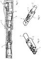
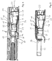
- the connector 1 has a housing 10.
- An electrical plug contact 12, a spring clamp connection 4 connected to the plug contact 12, two connection contacts 13, 14 for connecting the connector 1 to an electrical circuit board and a cover part 11 are arranged in the housing 10.
- the spring clamp connection 4, the plug contact 12 and the connection contacts 13, 14 form elements of a contact insert of the connector 1, which are at least predominantly surrounded by the housing 10.
- the housing 10 can also at least predominantly surround the cover part 11 .
- An electrical conductor 9 can be inserted through a conductor insertion opening 20 and clamped to the spring clamp connection 4 .
- connection contacts 13, 14 are formed on an underside of a base section 24 of the contact insert.
- Side walls 29 protrude upwards from the base section 24 , ie on the side facing away from the connection contacts 13 , 14 .
- the side walls 29 surround a conductor entry channel, ie the side walls form, so to speak, a left and a right side wall.
- a spring tongue 16 protrudes from each of the side walls 29 in a direction L of conductor insertion.
- the spring tongues 16 form clamping springs for clamping an electrical conductor.
- the spring tongues 16 end at their free end pointing away from the side walls 29 with a respective clamping edge 21 between which the electrical conductor can be clamped.
- the spring tongues 16 are free from the bottom section 24 so that they can freely deform elastically.
- An actuating tongue 25 is located on the upper side of the spring tongues 16 facing away from the base section 24.
- the base section 24 can be positioned at an angle to the conductor insertion direction L, at least in a certain area, in order to guide an electrical conductor inserted through a conductor insertion opening 20 to the clamping edges 21.
- the plug contact 12 is shown by way of example as a fork contact with two contact forks 12 .
- the contact forks 12 can be formed in one piece with the base section 24 and can be bent upwards relative to the base section 24 .
- the connector 1 has the cover part 11 already mentioned.
- the cover part 11 has a material area on the conductor insertion side of the connector 1 that forms the conductor insertion opening 20 .
- the conductor insertion opening 20 is thus formed integrally with the cover part 11 .
- the cover part 11 extends towards a first actuating device 15 for actuating the clamping springs of the spring-loaded terminal connection 4, d. H. the spring tongues 16.
- the first actuating device 15 can, for. B. in a downward deflection towards the actuating tongues 25 come into contact with them and thereby spread the spring tongues 16 apart.
- the cover part 11 can have a recess 30 on the upper side facing the housing 10 .
- the housing 10 can additionally have an actuation opening 22 .
- the first actuating device 15 and the depression 30 are arranged in alignment with this actuating opening 20 so that they can be easily actuated manually.
- the cover part 11 in the conductor insertion direction L forms a conductor guiding bevel 28 tapering downwards towards the base section 24 .
- the conductor guiding bevel 28 also guides the electrical conductor in a desired direction behind the clamping point, ie behind the clamping edges 21 .
- a conductor stop 19 is formed on the cover part 11 in the conductor insertion direction L.
- the ladder stop 19 can, for. B. remote from the conductor insertion opening 20 free end of the cover part 11 may be arranged, z. B. as a tongue of material directed downwards towards the bottom section 24 .
- the insertion depth of the electrical conductor inserted into the connector 1 is limited by the conductor stop 19 .
- the conductor stop 19 can be supported on the inside of the housing 10 .
- the figure 4 shows that the ladder stop 19 is supported both downwards towards the bottom section 24 at a contact point 26 in the vertical direction and additionally at a contact point 27 in the horizontal direction.
- the cover part 11 is supported in the region of the ladder stop 19 at the contact points 26, 27 and can carry out a slight pivoting movement that occurs as a result.
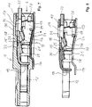
- the Figures 7 to 9 show in comparable views as that Figures 4 to 6 a further embodiment of a connector 1, in which, in addition to the features explained above, there is also a second actuating device 17, with which actuation of the clamping springs 16 of the spring-loaded terminal connection 4 can also be carried out.
- the second actuating device 17 is designed as a pusher that can be displaced in the conductor insertion direction L and is mounted in a bearing slot 18 of the cover part 11 with regard to its longitudinal movement.
- the second actuating device 17 is latched to the cover part 11 via latching elements 31, for example.
- the second actuating device 17 has a manual actuating area 33 which protrudes from the housing 10 counter to the direction L of conductor insertion.
- the second actuation device 17 has a tappet area 32, with which the spring tongues 16 and/or the actuation tongues 25 can be subjected to a force when a compressive force is exerted on the manual actuation area 33 in the conductor insertion direction L.
- the spring tongues 16 are then spread apart by the plunger area 32 and the clamping point is thereby opened.
- the Figures 10 and 11 illustrate the advantageous attachment of the cover part 11 to the housing based on the described embodiments of the connector 1 10.
- the cover part 11 can have connecting pins 23 arranged to the left and right of the conductor insertion opening 20, which can be inserted into connecting recesses in the housing 10 that are adapted thereto. In this way, the respective cover part 11 can be connected to the housing 10, z. B. be locked with it.
- the plug connector 1 in a multi-pole embodiment can have its own cover part 11 for each of the plug contacts 12 or each of the spring clamp terminals 4 .
- a common cover part 11 can also be used for several spring-loaded terminal connections 4 or plug-in contacts 12 .
Landscapes
- Coupling Device And Connection With Printed Circuit (AREA)
Priority Applications (1)
| Application Number | Priority Date | Filing Date | Title |
|---|---|---|---|
| EP25203946.6A EP4645604A3 (fr) | 2021-03-10 | 2022-03-09 | Connecteur électrique |
Applications Claiming Priority (1)
| Application Number | Priority Date | Filing Date | Title |
|---|---|---|---|
| DE102021105789.2A DE102021105789A1 (de) | 2021-03-10 | 2021-03-10 | Elektrischer Steckverbinder |
Related Child Applications (2)
| Application Number | Title | Priority Date | Filing Date |
|---|---|---|---|
| EP25203946.6A Division EP4645604A3 (fr) | 2021-03-10 | 2022-03-09 | Connecteur électrique |
| EP25203946.6A Division-Into EP4645604A3 (fr) | 2021-03-10 | 2022-03-09 | Connecteur électrique |
Publications (3)
| Publication Number | Publication Date |
|---|---|
| EP4057449A2 true EP4057449A2 (fr) | 2022-09-14 |
| EP4057449A3 EP4057449A3 (fr) | 2022-11-02 |
| EP4057449B1 EP4057449B1 (fr) | 2025-10-29 |
Family
ID=80685092
Family Applications (2)
| Application Number | Title | Priority Date | Filing Date |
|---|---|---|---|
| EP22161072.8A Active EP4057449B1 (fr) | 2021-03-10 | 2022-03-09 | Connecteur enfichable électrique |
| EP25203946.6A Pending EP4645604A3 (fr) | 2021-03-10 | 2022-03-09 | Connecteur électrique |
Family Applications After (1)
| Application Number | Title | Priority Date | Filing Date |
|---|---|---|---|
| EP25203946.6A Pending EP4645604A3 (fr) | 2021-03-10 | 2022-03-09 | Connecteur électrique |
Country Status (3)
| Country | Link |
|---|---|
| EP (2) | EP4057449B1 (fr) |
| CN (1) | CN115084887A (fr) |
| DE (1) | DE102021105789A1 (fr) |
Citations (1)
| Publication number | Priority date | Publication date | Assignee | Title |
|---|---|---|---|---|
| DE202016101387U1 (de) | 2016-03-11 | 2017-06-13 | Wieland Electric Gmbh | Federkraftanschluss |
Family Cites Families (9)
| Publication number | Priority date | Publication date | Assignee | Title |
|---|---|---|---|---|
| JP3855833B2 (ja) * | 2002-04-23 | 2006-12-13 | オムロン株式会社 | 電線接続コネクタ |
| US20110207372A1 (en) * | 2010-02-22 | 2011-08-25 | Ideal Industries, Inc. | Electrical Connector With Push-In Termination |
| US8882533B2 (en) | 2012-05-25 | 2014-11-11 | Tyco Electronics Corporation | Electrical connector having poke-in wire contact |
| WO2016164219A1 (fr) * | 2015-04-08 | 2016-10-13 | Phoenix Contact Development and Manufacturing, Inc. | Plaque à bornes |
| EP3465828B1 (fr) * | 2016-05-30 | 2022-09-28 | Weidmüller Interface GmbH & Co. KG | Borne à ressort pour conducteur |
| DE202018102775U1 (de) * | 2018-05-18 | 2019-08-22 | PTR HARTMANN GmbH | Elektrische Anschlussklemme für einen Klemmanschluss |
| DE202018106898U1 (de) | 2018-12-04 | 2020-03-05 | WAGO Verwaltungsgesellschaft mit beschränkter Haftung | Federanschlussklemme |
| CN109742561A (zh) | 2019-01-18 | 2019-05-10 | 慈溪市万捷电子有限公司 | 一种led-smd接线端子 |
| US10658770B1 (en) * | 2019-08-13 | 2020-05-19 | Dinkle Enterprise Co., Ltd. | Press and spring-back type terminal block |
-
2021
- 2021-03-10 DE DE102021105789.2A patent/DE102021105789A1/de active Pending
-
2022
- 2022-03-02 CN CN202210203997.5A patent/CN115084887A/zh active Pending
- 2022-03-09 EP EP22161072.8A patent/EP4057449B1/fr active Active
- 2022-03-09 EP EP25203946.6A patent/EP4645604A3/fr active Pending
Patent Citations (1)
| Publication number | Priority date | Publication date | Assignee | Title |
|---|---|---|---|---|
| DE202016101387U1 (de) | 2016-03-11 | 2017-06-13 | Wieland Electric Gmbh | Federkraftanschluss |
Also Published As
| Publication number | Publication date |
|---|---|
| EP4645604A2 (fr) | 2025-11-05 |
| EP4057449B1 (fr) | 2025-10-29 |
| EP4057449A3 (fr) | 2022-11-02 |
| EP4645604A3 (fr) | 2026-01-07 |
| CN115084887A (zh) | 2022-09-20 |
| DE102021105789A1 (de) | 2022-09-15 |
Similar Documents
| Publication | Publication Date | Title |
|---|---|---|
| DE102013111649B4 (de) | Einzelelement-Draht/Platte-Verbinder | |
| EP3298659B1 (fr) | Borne de connexion de conducteur | |
| DE60027611T2 (de) | Kabelverbinder mit gesteuerter Impedanz | |
| EP1816706B1 (fr) | Borne de connexion électrique | |
| EP3375046B1 (fr) | Borne de branchement électrique | |
| EP1111720A1 (fr) | Borne à ressort sans vis | |
| EP3743961B1 (fr) | Système modulaire permettant de fabriquer un appareil électrique et dispositif de serrage | |
| WO2017046129A1 (fr) | Borne de raccord pour raccorder un conducteur électrique | |
| EP1207588A1 (fr) | Connecteur électrique pour cable plat ou circuit imprimé flexible | |
| EP3375048B1 (fr) | Contact à enficher | |
| DE69212270T2 (de) | Elektrischer Verbinder zur Verbindung einer Leiterplatte mit einem Kabel | |
| EP0800233A1 (fr) | Ressort de contact, conçu spécialement pour un connecteur électrique | |
| DE102016112831B4 (de) | Anschlussklemme | |
| DE102012016281B4 (de) | Elektrische Verbindungsanordnung und deren Bauteile | |
| EP3782235B1 (fr) | Connecteur direct | |
| DE102013111571B4 (de) | Gerätegehäuse, Elektronikgeräte und Steckkontaktträger | |
| EP0865105A1 (fr) | Douille de connexion électrique avec ressort de contact et douille utilisable comme contact terminal | |
| DE202016008242U1 (de) | Steckkontakt | |
| DE102022102875A1 (de) | Kontaktelement und Leiteranschlussklemme zum Anschließen eines elektrischen Leiters | |
| DE102018121792B4 (de) | Elektrische Steckbuchse | |
| EP4057449B1 (fr) | Connecteur enfichable électrique | |
| EP4285444B1 (fr) | Contact électrique et borne conductrice formée avec celui-ci | |
| DE102024123887A1 (de) | Vorrichtung mit einer Leiterplattenklemme und einem elektrischen Steckverbinderkontakt | |
| EP4443656A1 (fr) | Module de contact pour le raccordement d'un conducteur électrique et borne de raccordement de conducteur dotée d'un tel module de contact | |
| DE19934284A1 (de) | Klemmvorrichtung für einen elektrischen Leiter |
Legal Events
| Date | Code | Title | Description |
|---|---|---|---|
| PUAI | Public reference made under article 153(3) epc to a published international application that has entered the european phase |
Free format text: ORIGINAL CODE: 0009012 |
|
| STAA | Information on the status of an ep patent application or granted ep patent |
Free format text: STATUS: THE APPLICATION HAS BEEN PUBLISHED |
|
| AK | Designated contracting states |
Kind code of ref document: A2 Designated state(s): AL AT BE BG CH CY CZ DE DK EE ES FI FR GB GR HR HU IE IS IT LI LT LU LV MC MK MT NL NO PL PT RO RS SE SI SK SM TR |
|
| PUAL | Search report despatched |
Free format text: ORIGINAL CODE: 0009013 |
|
| AK | Designated contracting states |
Kind code of ref document: A3 Designated state(s): AL AT BE BG CH CY CZ DE DK EE ES FI FR GB GR HR HU IE IS IT LI LT LU LV MC MK MT NL NO PL PT RO RS SE SI SK SM TR |
|
| RIC1 | Information provided on ipc code assigned before grant |
Ipc: H01R 13/11 20060101ALN20220923BHEP Ipc: H01R 13/04 20060101ALN20220923BHEP Ipc: H01R 11/05 20060101ALN20220923BHEP Ipc: H01R 12/51 20110101ALI20220923BHEP Ipc: H01R 4/48 20060101AFI20220923BHEP |
|
| STAA | Information on the status of an ep patent application or granted ep patent |
Free format text: STATUS: REQUEST FOR EXAMINATION WAS MADE |
|
| 17P | Request for examination filed |
Effective date: 20221201 |
|
| RBV | Designated contracting states (corrected) |
Designated state(s): AL AT BE BG CH CY CZ DE DK EE ES FI FR GB GR HR HU IE IS IT LI LT LU LV MC MK MT NL NO PL PT RO RS SE SI SK SM TR |
|
| P01 | Opt-out of the competence of the unified patent court (upc) registered |
Effective date: 20230516 |
|
| RAP3 | Party data changed (applicant data changed or rights of an application transferred) |
Owner name: WAGO VERWALTUNGSGESELLSCHAFT MBH |
|
| RAP3 | Party data changed (applicant data changed or rights of an application transferred) |
Owner name: WAGO VERWALTUNGSGESELLSCHAFT MBH |
|
| STAA | Information on the status of an ep patent application or granted ep patent |
Free format text: STATUS: EXAMINATION IS IN PROGRESS |
|
| 17Q | First examination report despatched |
Effective date: 20240425 |
|
| GRAP | Despatch of communication of intention to grant a patent |
Free format text: ORIGINAL CODE: EPIDOSNIGR1 |
|
| STAA | Information on the status of an ep patent application or granted ep patent |
Free format text: STATUS: GRANT OF PATENT IS INTENDED |
|
| RIC1 | Information provided on ipc code assigned before grant |
Ipc: H01R 13/11 20060101ALN20250519BHEP Ipc: H01R 13/04 20060101ALN20250519BHEP Ipc: H01R 11/05 20060101ALN20250519BHEP Ipc: H01R 12/51 20110101ALI20250519BHEP Ipc: H01R 4/48 20060101AFI20250519BHEP |
|
| INTG | Intention to grant announced |
Effective date: 20250530 |
|
| GRAS | Grant fee paid |
Free format text: ORIGINAL CODE: EPIDOSNIGR3 |
|
| GRAA | (expected) grant |
Free format text: ORIGINAL CODE: 0009210 |
|
| STAA | Information on the status of an ep patent application or granted ep patent |
Free format text: STATUS: THE PATENT HAS BEEN GRANTED |
|
| AK | Designated contracting states |
Kind code of ref document: B1 Designated state(s): AL AT BE BG CH CY CZ DE DK EE ES FI FR GB GR HR HU IE IS IT LI LT LU LV MC MK MT NL NO PL PT RO RS SE SI SK SM TR |
|
| REG | Reference to a national code |
Ref country code: CH Ref legal event code: F10 Free format text: ST27 STATUS EVENT CODE: U-0-0-F10-F00 (AS PROVIDED BY THE NATIONAL OFFICE) Effective date: 20251029 Ref country code: GB Ref legal event code: FG4D Free format text: NOT ENGLISH |
|
| REG | Reference to a national code |
Ref country code: IE Ref legal event code: FG4D Free format text: LANGUAGE OF EP DOCUMENT: GERMAN |
|
| REG | Reference to a national code |
Ref country code: DE Ref legal event code: R096 Ref document number: 502022005892 Country of ref document: DE |
|
| REG | Reference to a national code |
Ref country code: NL Ref legal event code: MP Effective date: 20251029 |
|
| PG25 | Lapsed in a contracting state [announced via postgrant information from national office to epo] |
Ref country code: ES Free format text: LAPSE BECAUSE OF FAILURE TO SUBMIT A TRANSLATION OF THE DESCRIPTION OR TO PAY THE FEE WITHIN THE PRESCRIBED TIME-LIMIT Effective date: 20251029 |
|
| REG | Reference to a national code |
Ref country code: LT Ref legal event code: MG9D |
|
| PG25 | Lapsed in a contracting state [announced via postgrant information from national office to epo] |
Ref country code: NO Free format text: LAPSE BECAUSE OF FAILURE TO SUBMIT A TRANSLATION OF THE DESCRIPTION OR TO PAY THE FEE WITHIN THE PRESCRIBED TIME-LIMIT Effective date: 20260129 |
|
| PGFP | Annual fee paid to national office [announced via postgrant information from national office to epo] |
Ref country code: DE Payment date: 20260107 Year of fee payment: 5 |
|
| PG25 | Lapsed in a contracting state [announced via postgrant information from national office to epo] |
Ref country code: FI Free format text: LAPSE BECAUSE OF FAILURE TO SUBMIT A TRANSLATION OF THE DESCRIPTION OR TO PAY THE FEE WITHIN THE PRESCRIBED TIME-LIMIT Effective date: 20251029 Ref country code: HR Free format text: LAPSE BECAUSE OF FAILURE TO SUBMIT A TRANSLATION OF THE DESCRIPTION OR TO PAY THE FEE WITHIN THE PRESCRIBED TIME-LIMIT Effective date: 20251029 |
|
| PGFP | Annual fee paid to national office [announced via postgrant information from national office to epo] |
Ref country code: AT Payment date: 20260301 Year of fee payment: 5 |
|
| PG25 | Lapsed in a contracting state [announced via postgrant information from national office to epo] |
Ref country code: NL Free format text: LAPSE BECAUSE OF FAILURE TO SUBMIT A TRANSLATION OF THE DESCRIPTION OR TO PAY THE FEE WITHIN THE PRESCRIBED TIME-LIMIT Effective date: 20251029 |
|
| PG25 | Lapsed in a contracting state [announced via postgrant information from national office to epo] |
Ref country code: RS Free format text: LAPSE BECAUSE OF FAILURE TO SUBMIT A TRANSLATION OF THE DESCRIPTION OR TO PAY THE FEE WITHIN THE PRESCRIBED TIME-LIMIT Effective date: 20260129 |
|
| PG25 | Lapsed in a contracting state [announced via postgrant information from national office to epo] |
Ref country code: IS Free format text: LAPSE BECAUSE OF FAILURE TO SUBMIT A TRANSLATION OF THE DESCRIPTION OR TO PAY THE FEE WITHIN THE PRESCRIBED TIME-LIMIT Effective date: 20260228 |
|
| PG25 | Lapsed in a contracting state [announced via postgrant information from national office to epo] |
Ref country code: PT Free format text: LAPSE BECAUSE OF FAILURE TO SUBMIT A TRANSLATION OF THE DESCRIPTION OR TO PAY THE FEE WITHIN THE PRESCRIBED TIME-LIMIT Effective date: 20260302 |
|
| PG25 | Lapsed in a contracting state [announced via postgrant information from national office to epo] |
Ref country code: PL Free format text: LAPSE BECAUSE OF FAILURE TO SUBMIT A TRANSLATION OF THE DESCRIPTION OR TO PAY THE FEE WITHIN THE PRESCRIBED TIME-LIMIT Effective date: 20251029 |
|
| PG25 | Lapsed in a contracting state [announced via postgrant information from national office to epo] |
Ref country code: LV Free format text: LAPSE BECAUSE OF FAILURE TO SUBMIT A TRANSLATION OF THE DESCRIPTION OR TO PAY THE FEE WITHIN THE PRESCRIBED TIME-LIMIT Effective date: 20251029 |