EP4059451A1 - Système de traitement médical - Google Patents
Système de traitement médical Download PDFInfo
- Publication number
- EP4059451A1 EP4059451A1 EP22153927.3A EP22153927A EP4059451A1 EP 4059451 A1 EP4059451 A1 EP 4059451A1 EP 22153927 A EP22153927 A EP 22153927A EP 4059451 A1 EP4059451 A1 EP 4059451A1
- Authority
- EP
- European Patent Office
- Prior art keywords
- conductor
- interventional element
- medical device
- lumen
- electrode portion
- Prior art date
- Legal status (The legal status is an assumption and is not a legal conclusion. Google has not performed a legal analysis and makes no representation as to the accuracy of the status listed.)
- Granted
Links
Images


Classifications
-
- A—HUMAN NECESSITIES
- A61—MEDICAL OR VETERINARY SCIENCE; HYGIENE
- A61B—DIAGNOSIS; SURGERY; IDENTIFICATION
- A61B17/00—Surgical instruments, devices or methods
- A61B17/22—Implements for squeezing-off ulcers or the like on inner organs of the body; Implements for scraping-out cavities of body organs, e.g. bones; for invasive removal or destruction of calculus using mechanical vibrations; for removing obstructions in blood vessels, not otherwise provided for
- A61B17/221—Gripping devices in the form of loops or baskets for gripping calculi or similar types of obstructions
-
- A—HUMAN NECESSITIES
- A61—MEDICAL OR VETERINARY SCIENCE; HYGIENE
- A61B—DIAGNOSIS; SURGERY; IDENTIFICATION
- A61B18/00—Surgical instruments, devices or methods for transferring non-mechanical forms of energy to or from the body
- A61B18/04—Surgical instruments, devices or methods for transferring non-mechanical forms of energy to or from the body by heating
- A61B18/12—Surgical instruments, devices or methods for transferring non-mechanical forms of energy to or from the body by heating by passing a current through the tissue to be heated, e.g. high-frequency current
-
- A—HUMAN NECESSITIES
- A61—MEDICAL OR VETERINARY SCIENCE; HYGIENE
- A61B—DIAGNOSIS; SURGERY; IDENTIFICATION
- A61B18/00—Surgical instruments, devices or methods for transferring non-mechanical forms of energy to or from the body
- A61B18/04—Surgical instruments, devices or methods for transferring non-mechanical forms of energy to or from the body by heating
- A61B18/12—Surgical instruments, devices or methods for transferring non-mechanical forms of energy to or from the body by heating by passing a current through the tissue to be heated, e.g. high-frequency current
- A61B18/1206—Generators therefor
-
- A—HUMAN NECESSITIES
- A61—MEDICAL OR VETERINARY SCIENCE; HYGIENE
- A61B—DIAGNOSIS; SURGERY; IDENTIFICATION
- A61B18/00—Surgical instruments, devices or methods for transferring non-mechanical forms of energy to or from the body
- A61B18/04—Surgical instruments, devices or methods for transferring non-mechanical forms of energy to or from the body by heating
- A61B18/12—Surgical instruments, devices or methods for transferring non-mechanical forms of energy to or from the body by heating by passing a current through the tissue to be heated, e.g. high-frequency current
- A61B18/14—Probes or electrodes therefor
-
- A—HUMAN NECESSITIES
- A61—MEDICAL OR VETERINARY SCIENCE; HYGIENE
- A61B—DIAGNOSIS; SURGERY; IDENTIFICATION
- A61B18/00—Surgical instruments, devices or methods for transferring non-mechanical forms of energy to or from the body
- A61B18/04—Surgical instruments, devices or methods for transferring non-mechanical forms of energy to or from the body by heating
- A61B18/12—Surgical instruments, devices or methods for transferring non-mechanical forms of energy to or from the body by heating by passing a current through the tissue to be heated, e.g. high-frequency current
- A61B18/14—Probes or electrodes therefor
- A61B18/1492—Probes or electrodes therefor having a flexible, catheter-like structure, e.g. for heart ablation
-
- A—HUMAN NECESSITIES
- A61—MEDICAL OR VETERINARY SCIENCE; HYGIENE
- A61B—DIAGNOSIS; SURGERY; IDENTIFICATION
- A61B18/00—Surgical instruments, devices or methods for transferring non-mechanical forms of energy to or from the body
- A61B18/04—Surgical instruments, devices or methods for transferring non-mechanical forms of energy to or from the body by heating
- A61B18/12—Surgical instruments, devices or methods for transferring non-mechanical forms of energy to or from the body by heating by passing a current through the tissue to be heated, e.g. high-frequency current
- A61B18/14—Probes or electrodes therefor
- A61B18/16—Indifferent or passive electrodes for grounding
-
- A—HUMAN NECESSITIES
- A61—MEDICAL OR VETERINARY SCIENCE; HYGIENE
- A61B—DIAGNOSIS; SURGERY; IDENTIFICATION
- A61B17/00—Surgical instruments, devices or methods
- A61B2017/00831—Material properties
- A61B2017/00867—Material properties shape memory effect
-
- A—HUMAN NECESSITIES
- A61—MEDICAL OR VETERINARY SCIENCE; HYGIENE
- A61B—DIAGNOSIS; SURGERY; IDENTIFICATION
- A61B17/00—Surgical instruments, devices or methods
- A61B17/22—Implements for squeezing-off ulcers or the like on inner organs of the body; Implements for scraping-out cavities of body organs, e.g. bones; for invasive removal or destruction of calculus using mechanical vibrations; for removing obstructions in blood vessels, not otherwise provided for
- A61B17/22031—Gripping instruments, e.g. forceps, for removing or smashing calculi
- A61B2017/22034—Gripping instruments, e.g. forceps, for removing or smashing calculi for gripping the obstruction or the tissue part from inside
-
- A—HUMAN NECESSITIES
- A61—MEDICAL OR VETERINARY SCIENCE; HYGIENE
- A61B—DIAGNOSIS; SURGERY; IDENTIFICATION
- A61B17/00—Surgical instruments, devices or methods
- A61B17/22—Implements for squeezing-off ulcers or the like on inner organs of the body; Implements for scraping-out cavities of body organs, e.g. bones; for invasive removal or destruction of calculus using mechanical vibrations; for removing obstructions in blood vessels, not otherwise provided for
- A61B17/221—Gripping devices in the form of loops or baskets for gripping calculi or similar types of obstructions
- A61B2017/2215—Gripping devices in the form of loops or baskets for gripping calculi or similar types of obstructions having an open distal end
-
- A—HUMAN NECESSITIES
- A61—MEDICAL OR VETERINARY SCIENCE; HYGIENE
- A61B—DIAGNOSIS; SURGERY; IDENTIFICATION
- A61B18/00—Surgical instruments, devices or methods for transferring non-mechanical forms of energy to or from the body
- A61B2018/00053—Mechanical features of the instrument of device
- A61B2018/00059—Material properties
- A61B2018/00071—Electrical conductivity
- A61B2018/00077—Electrical conductivity high, i.e. electrically conducting
-
- A—HUMAN NECESSITIES
- A61—MEDICAL OR VETERINARY SCIENCE; HYGIENE
- A61B—DIAGNOSIS; SURGERY; IDENTIFICATION
- A61B18/00—Surgical instruments, devices or methods for transferring non-mechanical forms of energy to or from the body
- A61B2018/00053—Mechanical features of the instrument of device
- A61B2018/00059—Material properties
- A61B2018/00071—Electrical conductivity
- A61B2018/00083—Electrical conductivity low, i.e. electrically insulating
-
- A—HUMAN NECESSITIES
- A61—MEDICAL OR VETERINARY SCIENCE; HYGIENE
- A61B—DIAGNOSIS; SURGERY; IDENTIFICATION
- A61B18/00—Surgical instruments, devices or methods for transferring non-mechanical forms of energy to or from the body
- A61B2018/00053—Mechanical features of the instrument of device
- A61B2018/00214—Expandable means emitting energy, e.g. by elements carried thereon
-
- A—HUMAN NECESSITIES
- A61—MEDICAL OR VETERINARY SCIENCE; HYGIENE
- A61B—DIAGNOSIS; SURGERY; IDENTIFICATION
- A61B18/00—Surgical instruments, devices or methods for transferring non-mechanical forms of energy to or from the body
- A61B2018/00053—Mechanical features of the instrument of device
- A61B2018/00214—Expandable means emitting energy, e.g. by elements carried thereon
- A61B2018/0022—Balloons
-
- A—HUMAN NECESSITIES
- A61—MEDICAL OR VETERINARY SCIENCE; HYGIENE
- A61B—DIAGNOSIS; SURGERY; IDENTIFICATION
- A61B18/00—Surgical instruments, devices or methods for transferring non-mechanical forms of energy to or from the body
- A61B2018/00315—Surgical instruments, devices or methods for transferring non-mechanical forms of energy to or from the body for treatment of particular body parts
- A61B2018/00345—Vascular system
- A61B2018/00398—Blood
-
- A—HUMAN NECESSITIES
- A61—MEDICAL OR VETERINARY SCIENCE; HYGIENE
- A61B—DIAGNOSIS; SURGERY; IDENTIFICATION
- A61B18/00—Surgical instruments, devices or methods for transferring non-mechanical forms of energy to or from the body
- A61B2018/00315—Surgical instruments, devices or methods for transferring non-mechanical forms of energy to or from the body for treatment of particular body parts
- A61B2018/00345—Vascular system
- A61B2018/00404—Blood vessels other than those in or around the heart
- A61B2018/0041—Removal of thrombosis
-
- A—HUMAN NECESSITIES
- A61—MEDICAL OR VETERINARY SCIENCE; HYGIENE
- A61B—DIAGNOSIS; SURGERY; IDENTIFICATION
- A61B18/00—Surgical instruments, devices or methods for transferring non-mechanical forms of energy to or from the body
- A61B2018/00571—Surgical instruments, devices or methods for transferring non-mechanical forms of energy to or from the body for achieving a particular surgical effect
- A61B2018/00577—Ablation
-
- A—HUMAN NECESSITIES
- A61—MEDICAL OR VETERINARY SCIENCE; HYGIENE
- A61B—DIAGNOSIS; SURGERY; IDENTIFICATION
- A61B18/00—Surgical instruments, devices or methods for transferring non-mechanical forms of energy to or from the body
- A61B18/04—Surgical instruments, devices or methods for transferring non-mechanical forms of energy to or from the body by heating
- A61B18/12—Surgical instruments, devices or methods for transferring non-mechanical forms of energy to or from the body by heating by passing a current through the tissue to be heated, e.g. high-frequency current
- A61B18/1206—Generators therefor
- A61B2018/1246—Generators therefor characterised by the output polarity
- A61B2018/1253—Generators therefor characterised by the output polarity monopolar
-
- A—HUMAN NECESSITIES
- A61—MEDICAL OR VETERINARY SCIENCE; HYGIENE
- A61B—DIAGNOSIS; SURGERY; IDENTIFICATION
- A61B18/00—Surgical instruments, devices or methods for transferring non-mechanical forms of energy to or from the body
- A61B18/04—Surgical instruments, devices or methods for transferring non-mechanical forms of energy to or from the body by heating
- A61B18/12—Surgical instruments, devices or methods for transferring non-mechanical forms of energy to or from the body by heating by passing a current through the tissue to be heated, e.g. high-frequency current
- A61B18/1206—Generators therefor
- A61B2018/1246—Generators therefor characterised by the output polarity
- A61B2018/126—Generators therefor characterised by the output polarity bipolar
-
- A—HUMAN NECESSITIES
- A61—MEDICAL OR VETERINARY SCIENCE; HYGIENE
- A61B—DIAGNOSIS; SURGERY; IDENTIFICATION
- A61B18/00—Surgical instruments, devices or methods for transferring non-mechanical forms of energy to or from the body
- A61B18/04—Surgical instruments, devices or methods for transferring non-mechanical forms of energy to or from the body by heating
- A61B18/12—Surgical instruments, devices or methods for transferring non-mechanical forms of energy to or from the body by heating by passing a current through the tissue to be heated, e.g. high-frequency current
- A61B18/1206—Generators therefor
- A61B2018/1266—Generators therefor with DC current output
-
- A—HUMAN NECESSITIES
- A61—MEDICAL OR VETERINARY SCIENCE; HYGIENE
- A61B—DIAGNOSIS; SURGERY; IDENTIFICATION
- A61B18/00—Surgical instruments, devices or methods for transferring non-mechanical forms of energy to or from the body
- A61B18/04—Surgical instruments, devices or methods for transferring non-mechanical forms of energy to or from the body by heating
- A61B18/12—Surgical instruments, devices or methods for transferring non-mechanical forms of energy to or from the body by heating by passing a current through the tissue to be heated, e.g. high-frequency current
- A61B18/14—Probes or electrodes therefor
- A61B2018/1405—Electrodes having a specific shape
-
- A—HUMAN NECESSITIES
- A61—MEDICAL OR VETERINARY SCIENCE; HYGIENE
- A61B—DIAGNOSIS; SURGERY; IDENTIFICATION
- A61B18/00—Surgical instruments, devices or methods for transferring non-mechanical forms of energy to or from the body
- A61B18/04—Surgical instruments, devices or methods for transferring non-mechanical forms of energy to or from the body by heating
- A61B18/12—Surgical instruments, devices or methods for transferring non-mechanical forms of energy to or from the body by heating by passing a current through the tissue to be heated, e.g. high-frequency current
- A61B18/14—Probes or electrodes therefor
- A61B2018/1405—Electrodes having a specific shape
- A61B2018/142—Electrodes having a specific shape at least partly surrounding the target, e.g. concave, curved or in the form of a cave
-
- A—HUMAN NECESSITIES
- A61—MEDICAL OR VETERINARY SCIENCE; HYGIENE
- A61B—DIAGNOSIS; SURGERY; IDENTIFICATION
- A61B2218/00—Details of surgical instruments, devices or methods for transferring non-mechanical forms of energy to or from the body
- A61B2218/001—Details of surgical instruments, devices or methods for transferring non-mechanical forms of energy to or from the body having means for irrigation and/or aspiration of substances to and/or from the surgical site
- A61B2218/002—Irrigation
-
- A—HUMAN NECESSITIES
- A61—MEDICAL OR VETERINARY SCIENCE; HYGIENE
- A61B—DIAGNOSIS; SURGERY; IDENTIFICATION
- A61B2218/00—Details of surgical instruments, devices or methods for transferring non-mechanical forms of energy to or from the body
- A61B2218/001—Details of surgical instruments, devices or methods for transferring non-mechanical forms of energy to or from the body having means for irrigation and/or aspiration of substances to and/or from the surgical site
- A61B2218/007—Aspiration
Definitions
- the present technology relates to relates generally to devices, systems, and methods for removing obstructions from body lumens. Some embodiments of the present technology relate to devices and methods for delivering electrical current within a medical treatment system.
- an obstruction such as clot material
- An inherent risk in such procedures is that mobilizing or otherwise disturbing the obstruction can potentially create further harm if the obstruction or a fragment thereof dislodges from the retrieval device. If all or a portion of the obstruction breaks free from the device and flows downstream, it is highly likely that the free material will become trapped in smaller and more tortuous anatomy. In many cases, the physician will no longer be able to use the same retrieval device to again remove the obstruction because the device may be too large and/or immobile to move the device to the site of the new obstruction.
- Procedures for treating ischemic stroke by restoring flow within the cerebral vasculature are subject to the above concerns.
- the brain relies on its arteries and veins to supply oxygenated blood from the heart and lungs and to remove carbon dioxide and cellular waste from brain tissue. Blockages that interfere with this blood supply eventually cause the brain tissue to stop functioning. If the disruption in blood occurs for a sufficient amount of time, the continued lack of nutrients and oxygen causes irreversible cell death. Accordingly, it is desirable to provide immediate medical treatment of an ischemic stroke.
- a physician To access the cerebral vasculature, a physician typically advances a catheter from a remote part of the body (typically a leg) through the abdominal vasculature and into the cerebral region of the vasculature. Once within the cerebral vasculature, the physician deploys a device for retrieval of the obstruction causing the blockage. Concerns about dislodged obstructions or the migration of dislodged fragments increases the duration of the procedure at a time when restoration of blood flow is paramount. Furthermore, a physician might be unaware of one or more fragments that dislodge from the initial obstruction and cause blockage of smaller more distal vessels.
- thrombectomies i.e. clot removal
- the physician deploys a stent into the clot in an attempt to push the clot to the side of the vessel and re-establish blood flow.
- Tissue plasminogen activator (“tPA”) is often injected into the bloodstream through an intravenous line to break down a clot.
- tPA tissue plasminogen activator
- it takes time for the tPA to reach the clot because the tPA must travel through the vasculature and only begins to break up the clot once it reaches the clot material.
- tPA is also often administered to supplement the effectiveness of the stent.
- the physician can attempt to remove the stent while it is expanded against or enmeshed within the clot. In doing so, the physician must effectively drag the clot through the vasculature, in a proximal direction, into a guide catheter located within vessels in the patient's neck (typically the carotid artery). While this procedure has been shown to be effective in the clinic and easy for the physician to perform, there remain some distinct disadvantages to using this approach.
- the stent may not sufficiently retain the clot as it pulls the clot to the catheter. In such a case, some or all of the clot might remain in the vasculature.
- Another risk is that, as the stent mobilizes the clot from the original blockage site, the clot might not adhere to the stent as the stent is withdrawn toward the catheter. This is a particular risk when passing through bifurcations and tortuous anatomy.
- blood flow can carry the clot (or fragments of the clot) into a branching vessel at a bifurcation. If the clot is successfully brought to the end of the guide catheter in the carotid artery, yet another risk is that the clot may be "stripped" or "sheared” from the stent as the stent enters the guide catheter.
- Certain blood components such as platelets and coagulation proteins, display negative electrical charges.
- the treatment systems of the present technology provide an interventional element and a current generator configured to positively charge the interventional element during one or more stages of a thrombectomy procedure.
- the current generator may apply a constant or pulsatile direct current (DC) to the interventional element.
- the positively charged interventional element attracts negatively charged blood components, thereby improving attachment of the thrombus to the interventional element and reducing the number of device passes or attempts necessary to fully retrieve the clot.
- the treatment system includes an elongate core assembly (e.g., a cable) extending between the current generator and the interventional element.
- a delivery electrode may be integrated into the core assembly and/or interventional element, and the treatment system further includes a negative electrode that may be disposed at a number of different locations.
- the negative electrode can be a wire coupled to or integrated within the core assembly.
- a negative electrode can take the form of a needle, a grounding pad, a conductive element carried by a one or more catheters of the treatment system, a separate guide wire, and/or any other suitable conductive element configured to complete an electrical circuit with the delivery electrode and the extracorporeally positioned current generator.
- One approach to delivering current to an interventional element is to conduct current along a core member coupled to a proximal end of the interventional element.
- this approach can lead to disadvantageous concentration of electrical charge along a proximal portion of the interventional element, with insufficient charge density in more distal portions of the interventional element (e.g., along some or all of the working length of the interventional element).
- This is particularly true of an interventional element having a proximal portion that tapers to a connection point with the core member.
- This concentration of current in the proximal portion can reduce the efficacy of electrostatic enhancement of clot adhesion, as the mechanical clot engagement occurs primarily at a location distal to the region at which the charge density is greatest.
- hydrogen and chlorine gas bubbles can form along the surface of the interventional element in areas with high surface charge density (e.g., along a proximal portion of the interventional element).
- the entire interventional element exhibits a positive electrical charge, all portions of the interventional element can attract negatively charged blood components, thereby improving attachment of the thrombus to the interventional element.
- portions of the interventional element are not positively charged (e.g., the distal portion is electrically neutral or exhibits insufficient charge density), those portions of the interventional element may not adequately attract negatively charged blood components, which can prevent improved attachment of the thrombus to the interventional element.
- Embodiments of the present technology address these and other problems by providing a core assembly that positions negative electrode(s) relative to the interventional element at locations that facilitate current distribution across the interventional element.
- the negative electrode can be positioned at or distal to the interventional element in a manner that encourages current to flow through all portions of the interventional element.
- the core assembly can take the form of an elongated conductor such as a wire, with an insulation material surrounding the wire along its length.
- the insulation material can include gaps or apertures along a distal region of the wire that define negative electrode(s). These uninsulated sections can be located at specific locations that encourage current to flow through the entire interventional element.
- one or more negative electrodes can be located proximate the distal end of the interventional element, which encourages current to flow to the distal end of the interventional element.
- the interventional element can reliably maintain a positive charge during treatment.
- the present technology provides devices, systems, and methods for removing clot material from a blood vessel lumen. Although many of the embodiments are described below with respect to devices, systems, and methods for treating a cerebral or intracranial embolism, other applications and other embodiments, in addition to those described herein, are within the scope of the technology.
- the treatment systems and methods of the present technology may be used to remove emboli from body lumens other than blood vessels (e.g., the digestive tract, etc.) and/or may be used to remove emboli from blood vessels outside of the brain (e.g., pulmonary, abdominal, cervical, or thoracic blood vessels, or peripheral blood vessels including those within the legs or arms, etc.).
- the treatment systems and methods of the present technology may be used to remove luminal obstructions other than clot material (e.g., plaque, resected tissue, foreign material, etc.).
- luminal obstructions e.g., plaque, resected tissue, foreign material, etc.
- aspects of the present technology can be applied to medical devices and systems that are not configured for removal of material from vessel lumens, for example systems and devices for ablation, neuromodulation, or any other suitable medical procedure.
- FIG. 1A illustrates a view of an electrically enhanced treatment system 100 according to one or more embodiments of the present technology.
- the treatment system 100 can include a current generator 102 and a treatment device 104 having a proximal portion 104a configured to be coupled to the current generator 102 and a distal portion 104b configured to be intravascularly positioned within a blood vessel (such as an intracranial blood vessel) at a treatment site at or proximate a thrombus.
- the treatment device 104 includes an interventional element 106 at the distal portion 104b, a handle 108 at the proximal portion 104a, and a plurality of elongated shafts or members extending therebetween.
- the treatment device 104 includes a first catheter 110 (such as a guide catheter or balloon guide catheter), a second catheter 112 (such as a distal access catheter or aspiration catheter) configured to be slidably disposed within a lumen of the first catheter 110, and a third catheter 114 (such as a microcatheter) configured to be slidably disposed within a lumen of the second catheter 112.
- the treatment device 104 can include a core assembly 105 extending between the proximal portion 104a and distal portion 104b of the treatment device 104.
- the treatment device 104 does not include the first catheter 110 and/or the second catheter 112.
- the core assembly 105 is configured to be slidably disposed within the lumen of the third catheter 114.
- the core assembly 105 can take the form of an electrical cable or other such assembly that includes a first electrical conductor 116 and a second electrical conductor 118.
- the first conductor 116 can take the form of an elongated tube (e.g., a hypotube) made of or including an electrically conductive material
- the second conductor 118 can take the form of an elongated wire or rod that is made of or includes an electrically conductive material.
- the second conductor 118 is configured to be disposed within a lumen of the first conductor 116.
- the first conductor 116 and second conductor 118 are coaxial.
- the first conductor 116 and second conductor 118 are non-slidably coupled together.
- the first conductor 116 and second conductor 118 can be sized and configured to be advanced through a corporeal lumen to the treatment site.
- the first conductor 116 and second conductor 118 can be sized to be positioned proximate a thrombus within a lumen of a blood vessel, such as within a patient's neurovasculature.
- the first conductor 116 and/or the second conductor 118 can be electrically insulated along at least a portion of their respective lengths.
- the first catheter 110 can be coupled to (or incorporate) the handle 108, which provides proximal access to the first conductor 116 and second conductor 118.
- the current generator 102 may be coupled to the core assembly 105 to deliver electrical current to the interventional element 106 and thereby provide an electrically charged environment at the distal portion 104b of the treatment device 104. Further, the current generator 102 may be coupled to the core assembly 105 to return electrical current from the electrically charged environment to the current generator 102. In various embodiments, the current generator 102 can be electrically coupled to the first conductor 116, the second conductor 118, or both.
- the treatment system 100 includes a suction source 120 (e.g., a syringe, a pump, etc.) configured to be fluidically coupled (e.g., via a connector 122) to a proximal portion of one or more of the first catheter 110, the second catheter 112, and/or the third catheter 114 to apply negative pressure therethrough.
- a suction source 120 e.g., a syringe, a pump, etc.
- the treatment system 100 includes a fluid source 124 (e.g., a fluid reservoir, a syringe, pump, etc.) configured to be fluidically coupled (e.g., via the connector 122) to a proximal portion of one or more of the first catheter 110, the second catheter 112, and/or the third catheter 114 to supply fluid (e.g., saline, contrast agents, a drug such as a thrombolytic agent, etc.) to the treatment site.
- a fluid source 124 e.g., a fluid reservoir, a syringe, pump, etc.
- fluid e.g., a fluid reservoir, a syringe, pump, etc.
- the catheters 110, 112, and 114 can each be formed as a generally tubular member extending along and about a central axis.
- the third catheter 114 is generally constructed to track over a conventional guidewire in the cervical anatomy and into the cerebral vessels associated with the brain and may also be chosen according to several standard designs that are generally available. Accordingly, the third catheter 114 can have a length that is at least 125 cm long, and more particularly may be between about 125 cm and about 175 cm long. Other designs and dimensions are contemplated.
- the second catheter 112 can be sized and configured to slidably receive the third catheter 114 therethrough.
- the second catheter 112 can be coupled at a proximal portion to a suction source 120 ( FIG. 1A ) such as a pump or syringe in order to supply negative pressure to a treatment site.
- the first catheter 110 can be sized and configured to slidably receive both the second catheter 112 and the third catheter 114 therethrough.
- the first catheter 110 is a balloon guide catheter having an inflatable balloon or other expandable member surrounding the catheter shaft at or near its distal end.
- the first catheter 110 can first be advanced through a vessel and then its balloon can be expanded to anchor the first catheter 110 in place and/or arrest blood flow from areas proximal of the balloon, e.g. to enhance the effectiveness of aspiration performed via the first catheter 110 and/or other catheter(s).
- a guide catheter without a balloon can be employed.
- the second catheter 112 can be advanced through the first catheter 110 until its distal end extends distally beyond the distal end of the first catheter 110.
- the second catheter 112 can be positioned such that its distal end is adjacent or proximal of a treatment site (e.g., a site of a blood clot within the vessel).
- the third catheter 114 may then be advanced through the second catheter 112 until its distal end extends distally beyond the distal end of the second catheter 112.
- the interventional element 106 may then be advanced through the third catheter 114 via the core assembly 105 for delivery to the treatment site.
- the bodies of the catheters 110, 112, and 114 can be made from various thermoplastics, e.g., polytetrafluoroethylene (PTFE or TEFLON ® ), fluorinated ethylene propylene (FEP), high-density polyethylene (HDPE), polyether ether ketone (PEEK), etc., which can optionally be lined on the inner surface of the catheters or an adjacent surface with a hydrophilic material such as polyvinylpyrrolidone (PVP) or some other plastic coating. Additionally, either surface can be coated with various combinations of different materials, depending upon the desired results.
- PTFE or TEFLON ® polytetrafluoroethylene
- FEP fluorinated ethylene propylene
- HDPE high-density polyethylene
- PEEK polyether ether ketone
- the current generator 102 may be coupled to a proximal portion of the first conductor 116, and/or a proximal portion of the third catheter 114, the second catheter 112, and/or first catheter 110 to provide an electric current to the interventional element 106.
- the current generator 102 can be coupled to a proximal portion of the core assembly 105 and/or the first conductor 116 such that the first conductor 116 functions as a first conductive path (e.g., as a positive conductive path transmitting current from the current generator to the treatment site).
- a first conductive path e.g., as a positive conductive path transmitting current from the current generator to the treatment site.
- the current generator 102 can also be coupled to a proximal portion of the second conductor 118 such that the second conductor 118 functions as a second conductive path (e.g., as a negative conductive path transmitting current from the treatment site to the current generator 102).
- the negative electrode can be separate from the second conductor 118.
- the positive electrode can comprise the interventional element 106, and the negative electrode can be carried by one or more of the third catheter 114, the second catheter 112, and/or first catheter 110, or be coupled to or formed by a portion of the second conductor 118.
- the negative electrode can be provided via one or more external electrodes, such as a needle puncturing the patient, or a grounding pad applied to the patient's skin; in some such embodiments, or otherwise, the first conductor 116 or the second conductor 118 may be omitted from the core assembly 105.
- external electrodes such as a needle puncturing the patient, or a grounding pad applied to the patient's skin; in some such embodiments, or otherwise, the first conductor 116 or the second conductor 118 may be omitted from the core assembly 105.
- the system can include multiple (e.g., two or more), distinct conductive paths or channels for passing electrical current along the system.
- the interventional element 106 can serve as one electrode (e.g., a positive electrode) in electrical communication with a conductive path via the first conductor 116.
- Another of the conductive paths of the system can be in electrical communication with another electrode (e.g., a negative electrode).
- the second conductor 118 can serve as the second conductive path, with one or more uninsulated portions of the second conductor 118 forming the negative electrode(s).
- the first conductor 116 and the interventional element 106 can be joined at a connection 126 to secure the interventional element 106 relative to the first conductor 116 and to complete an electrical pathway between the elongate first conductor 116 and the interventional element 106.
- the distal end portion of the second conductor 118 is configured to be positioned distal of the distal end portion of the first conductor 116.
- the interventional element 106 can be metallic or otherwise electrically conductive so that when the interventional element 106 is placed in the presence of blood (or thrombus, and/or any other electrolytic medium which may be present, such as saline) and voltage is applied via the electrical connectors of the current generator 102, current flows from the positive connector of the current generator 102, distally along the first conductor 116 to the interventional element 106 and through the surrounding media (e.g., blood, tissue, thrombus, etc.) before returning proximally along the second conductor 118 to the negative electrical connector of the current generator 102, thereby positively charging at least a portion of the interventional element 106 and promoting clot adhesion.
- blood or thrombus, and/or any other electrolytic medium which may be present, such as saline
- the surrounding media e.g., blood, tissue, thrombus, etc.
- the polarities of the current generator 102 can be switched, so that the negative electrical connector is electrically coupled to the first conductor 116 and the positive electrical connector is electrically coupled to the second conductor 118.
- This can be advantageous when, for example, attempting to attract predominantly positively charged material to the interventional element 106, or when attempting to break up a clot rather than grasp it with an interventional element 106.
- alternating current (AC) signals may be used rather than DC. In certain instances, AC signals may advantageously help break apart a thrombus or other material.
- the interventional element 106 can take any number of forms, for example a removal device, a thrombectomy device, or other suitable medical device.
- the interventional element 106 may be a stent and/or stent retriever, such as Medtronic's Solitaire TM Revascularization Device, Stryker Neurovascular's Trevo ® ProVue TM Stentriever, or other suitable devices.
- the interventional element 106 may be a coiled wire, a weave, and/or a braid formed of a plurality of braided filaments. Examples of suitable interventional elements 106 include any of those disclosed in U.S. Patent No. 7,300,458, filed November 5, 2007 , U.S.
- Patent No. 8,940,003, filed November 22, 2010 U.S. Patent No. 9,039,749, filed October 1, 2010
- U.S. Patent No. 8,066,757, filed December 28, 2010 each of which is incorporated by reference herein in its entirety.
- the interventional element 106 can have a low-profile, constrained or compressed configuration for intravascular delivery to the treatment site within the third catheter 114, and an expanded configuration for securing and/or engaging clot material and/or for restoring blood flow at the treatment site.
- the interventional element 106 has a proximal portion including an attachment portion 106a that may be coupled to the first conductor 116 and a distal portion comprising an open cell framework or body 106b.
- the body 106b of the interventional element 106 can be generally tubular (e.g., cylindrical), and the proximal portion of the interventional element 106 can taper proximally to the attachment portion 106a.
- the interventional element 106 can define a lumen that is located radially inward from the body 106b.
- the interventional element 106 can be a metallic and/or electrically conductive thrombectomy device.
- the interventional element can include or be made of stainless steel, nitinol, cobalt-chromium, platinum, tantalum, alloys thereof, or any other suitable material.
- the interventional element 106 is a mesh structure (e.g., a braid, a stent, etc.) formed of a superelastic material (e.g., Nitinol) or other resilient or self-expanding material configured to self-expand when released from the third catheter 114.
- the mesh structure may include a plurality of struts and open spaces between the struts. In some embodiments, the struts and spaces may be situated along the longitudinal direction of the interventional element 106, the radial direction, or both.
- the first conductor 116 can be a structural element configured to push and pull a device such as the interventional element 106 along the bodily lumen.
- the first conductor 116 can be any suitable elongate member configured to advance the interventional element 106 to a treatment site within a blood vessel.
- the first conductor 116 can be or include a wire, tube (e.g., a hypotube), coil, or any combination thereof.
- the first conductor 116 comprises an elongate tubular member defining a lumen therethrough.
- the first conductor 116 can comprise a distally located aperture configured to receive the attachment portion of the interventional element.
- the first conductor 116 comprises a distally located joining element comprising the aperture configured to receive the attachment portion.
- the first conductor 116 can have a length sufficient to extend from a location outside the patient's body through the vasculature to a treatment site within the patient's body.
- the first conductor 116 can be a monolithic structure or formed of multiple joined segments.
- the first conductor 116 can comprise a laser-cut hypotube having a spiral cut pattern (or other pattern of cut voids) formed in its sidewall along at least a portion of its length.
- the first conductor 116 can be metallic and/or otherwise electrically conductive to deliver current from the current generator 102 to the interventional element 106.
- the first conductor 116 can comprise or consist of nickel titanium alloy, stainless steel, or other metals or alloys. In embodiments that comprise multiple joined segments, the segments may be of the same or different materials. For example, some or all of the first conductor 116 can be formed of stainless steel, or other suitable materials known to those skilled in the art. Nickel titanium alloy may be preferable for kink resistance and reduction of imaging artifacts.
- the second conductor 118 can be a structural element configured to secure or retain a position of the interventional element 106 relative to the first conductor 116. Additionally, or alternatively, the second conductor 118 can be configured to be a negative electrode.
- the second conductor 118 can be any suitable elongate member configured to extend through a lumen of the first conductor 116.
- the second conductor 118 can be or include a wire, tube (e.g., a hypotube), coil, or any combination thereof.
- the second conductor 118 can have a length sufficient to extend from a location outside the patient's body through the vasculature to a treatment site within the patient's body.
- the second conductor 118 can be a monolithic structure or formed of multiple joined segments.
- the second conductor 118 can be metallic or electrically conductive to deliver current from the surrounding media (e.g., blood, tissue, thrombus, etc.) to the current generator 200.
- the second conductor 118 can comprise or consist of nickel titanium alloy, stainless steel, or other metals or alloys. In embodiments that comprise multiple joined segments, the segments may be of the same or different materials.
- some or all of the second conductor 118 can be formed of stainless steel, or other suitable materials known to those skilled in the art.
- Nickel titanium alloy may be preferable for kink resistance and reduction of imaging artifacts.
- the second conductor 118 can be electrically insulated along some or all of its length.
- the second conductor 118 comprises an insulated wire or guide wire having one or more exposed, electrically conductive portions.
- a distal end portion of the second conductor 118 can be exposed to conduct current from surrounding media (e.g., blood, tissue, thrombus, etc.) at a treatment site.
- the treatment device 104 can comprise one or more electrically insulating materials.
- an insulating material can be disposed on one or more portions of the second conductor 118 to electrically isolate the second conductor 118 from the first conductor 116, the connection 126, and/or the interventional element 106.
- an insulating material can be disposed within a lumen of the first conductor 116 to electrically isolate the first conductor 116 from the second conductor 118 and/or the attachment portion of the interventional element 106.
- an insulating material is disposed over an outer surface of the first conductor 116 along at least a portion of a length of the first conductor 116 to direct current through the first conductor 116 and prevent current loss from the first conductor 116 to the surrounding environment.
- an insulating material 127 can be disposed adjacent to a proximal end portion 116a and/or a distal end portion 116b of the first conductor 116.
- the insulating material 127 may be disposed along an entire length of the first conductor 116 and/or the second conductor 118 or the insulating material may be disposed along select portions of the first conductor 116 and/or the second conductor 118.
- the insulating material 127 may comprise a polymer, such as polyimide, parylene, PTFE, or another suitable electrically insulating material.
- the interventional element 106 and the first conductor 116 can be coupled at a connection 126.
- the interventional element 106 and the first conductor 116 can be substantially permanently attached together at the connection 126. That is, the interventional element 106 and the first conductor 116 can be attached together in a manner that, under the expected use conditions of the device, the interventional element 106 and the first conductor 116 would not become unintentionally separated from one another.
- the treatment device 104 can comprise a portion, located proximally or distally of the connection 126, that is configured for selective detachment of the interventional element 106 from the first conductor 116.
- such a portion can comprise an electrolytically severable segment of the first conductor 116.
- the device can be devoid of any feature that would permit selective detachment of the interventional element 106 from the first conductor 116.
- the connection 126 can provide a mechanical interlock between the interventional element 106 and the first conductor 116.
- the connection 126 can be configured to complete an electrically conductive path between the interventional element 106 and the elongate first conductor 116.
- FIG. 1C illustrates an enlarged perspective view of the connection 126, according to some embodiments, between the first conductor 116 and the interventional element 106.
- the first conductor 116 comprises a distally located joining element 128 including an aperture 130 configured to receive a proximally located attachment portion 106a of the interventional element 106 and/or at least a portion of the second conductor 118.
- the attachment portion 106a of the interventional element 106 is configured to mechanically interlock with a joining element 128 to secure the interventional element 106 to the core assembly 105.
- the second conductor 118 can be disposed within the aperture at a radially adjacent position relative to the attachment portion 106a to facilitate such securement. Further, the second conductor 118 may be affixed to the joining element 128 via a weld, an adhesive, a threaded connection, an interference fit, or any other suitable connection.
- connection 126 can comprise a bonding agent in addition or alternative to the joining element 128 and/or second conductor 118.
- the bonding agent can comprise adhesive, solder, welding flux, brazing filler, etc., disposed within the joining element 128, and/or adjacent to it, just proximal of and/or just distal of the joining element 128.
- the bonding agent can bond to the connection 126 without applying heat.
- the bonding agent can comprise a UV-curable adhesive.
- use of a bonding agent that avoids application of heat that would damage the polymer may be preferred.
- connection 126 can comprise a locking element.
- the locking element can be coupled with the joining element 128 and can be configured to inhibit motion of the attachment portion 106a.
- suitable locking elements can include any of the disclosed locking elements in U.S. Provisional Application No. 63/199,352 filed December 21, 2020 , which is hereby incorporated by reference in its entirety.
- FIG. 2 is a plan view of the interventional element 106, depicted in an unfurled or flattened configuration for ease of understanding.
- the interventional element 106 has a proximal portion that may be coupled to the first conductor 116 and a distal portion.
- the interventional element 106 has a proximal portion including an attachment portion 106a that may be coupled to the first conductor 116 and a distal portion comprising an open cell framework or body 106b.
- the attachment portion 106a of the interventional element 106 can have a substantially constant thickness, such as would result from the interventional element 106 being cut from a tube or sheet of material, for example. In other embodiments, the thickness of the attachment portion 106a can vary across its length, width, or both.
- FIG. 3 illustrates a side schematic view of a portion of the treatment device 104.
- the interventional element 106 extends distally from the first conductor 116.
- the interventional element 106 can be in electrical communication with the first conductor 116, such that current supplied to a proximal end of the first conductor 116 is carried through the first conductor 116 to the interventional element 106.
- the second conductor 118 can extend through the lumen of the first conductor 116 and beyond a distal end of the first conductor 116, such that a distal portion of the second conductor 118 extends through an interior region of the interventional element 106.
- the second conductor 118 can be covered with an electrically insulative material 142 along at least a portion of its length. At one or more positions along a distal region of the second conductor 118, the insulative material 142 can form gaps or apertures that each define an electrode portion 140 formed by the exposed conductive metal of the underlying second conductor 118.
- current can flow from the interventional element 106, through surrounding media (e.g., blood, saline, etc.), to the electrode portions 140, and along the second conductor 118 to return to the current generator.
- the second conductor 118 can include an insulative material 142 that surrounds the second conductor 118 and which has several openings formed within the insulative material 142. These openings can define electrode portions 140.
- the insulative material 142 can be the same, or similar to, the insulative material 127. Accordingly, the portions of the second conductor 118 that are surrounded by the insulative material 142 can be electrically isolated from other components, while the openings formed within the insulative material 142 can provide electrical access to the second conductor 118 at the openings.
- the electrode portions 140 include a coating or other conductive element that is applied over the surface of the second conductor 118.
- the insulative material 142 can define the electrode portions 140.
- the electrode portions 140 can be defined by the regions of the second conductor 118 that are uncovered by the insulative material 142.
- the electrode portions 140 can be defined by the portions of the second conductor 118 that are uncovered by the insulative material 142 and any intervening insulative material 142 between the uncovered portions of the second conductor.
- the treatment device 104 can include one or more electrode portions 140 at or near the distal end of the second conductor 118.
- the electrode portions 140 can take the form of one or more discrete electrodes coupled to the second conductor 118.
- the electrode portions 140 of the second conductor 118 can be disposed radially adjacent to or distal of interventional element 106.
- the electrode portions 140 can be disposed distally of the connection 126 and be positioned radially inward of the interventional element 106.
- one or more electrode portions 140 extend (or are positioned) distally of the distal end of the interventional element 106.
- the second conductor 118 and electrode portions 140 are disposed within the lumen of the interventional element 106.
- the openings formed within the insulating material 142 can be disposed proximate or radially adjacent to the spaces or cell openings 107 bounded by the struts of the body 106b of the interventional element 106.
- each of the electrode portions 140 of the second conductor 118 is positioned radially adjacent to a cell opening 107 of the interventional element 106, and/or each portion of the second conductor 118 that is radially adjacent to a strut (and/or other metallic component, such as a radiopaque marker) of the interventional element 106 is insulated.
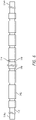
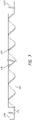
- FIGS. 4 to 7 illustrate several schematic views of the second conductor 118, according to one or more embodiments of the present technology.
- an insulative material 142 can couple to the second conductor 118.
- the insulative material 142 can couple to the outer surface of the second conductor 118.
- the insulative material 142 surrounds the second conductor 118.
- the insulating material 142 can extend along at least a portion of the length of second conductor 118.
- the insulating material 142 can extend from a proximal end portion 118a of the second conductor 118 to a distal end portion 118b of the second conductor 118.
- the insulating material 142 may comprise a polymer, such as polyimide, parylene, PTFE, or another suitable electrically insulating material.
- the insulating material 142 can define one or more electrode portions 140 of the second conductor 118.
- the electrode portions 140 can include one or more uninsulated portions of the second conductor 118 that allow for the second conductor 118 to electrically couple to other components via, e.g., surrounding media such as thrombus, blood, saline, tissue, etc.
- the distal end 118b of the second conductor 118 can be uninsulated, allowing for that portion of the second conductor 118 to electrically couple to other components or media.
- the electrode portions 140 can be disposed along one or more locations of the second conductor 118.
- one or more electrode portions 140 can be spaced apart from a distal terminus 118b of the second conductor 118 by a portion of the insulative material 142.
- the electrode portions 140 can include one or more openings 144 formed into the insulating material 142.
- multiple openings 144 can be formed along the length of the insulating material 142.
- the openings 144 can expose a portion of the second conductor 118 and allow for the second conductor 118 to electrically couple with another component or media.
- the openings 144 can be spaced apart along the length of insulating material 142.
- the openings 144 are evenly spaced along the length of the insulating material 142.
- the openings 144 are unevenly spaced along the length of the insulating material 142.
- more openings 144 can be formed near the distal end of the insulating material 142 than the proximal end of the insulating material 142.
- the openings 144 can take the form of one or more shapes, including circular, elliptical, regular polygonal, irregular polygonal, triangular, square, rectangular, pentagonal, hexagonal, or any other suitable shape.
- some or all of the electrode portions 140/openings 144 can be located at the same angular position about the longitudinal axis of the second conductor 118, e.g. at the "twelve o'clock" position on the second conductor.
- That angular position can be oriented to face away from the portion of the interventional element 106 which is nearest to the second conductor 118 (and/or to face radially inward toward the lumen or longitudinal axis of the interventional element). Such an orientation helps minimize the risk of electrical shorts arising from inadvertent contact of the electrode portions 140 with the struts of the interventional element. Furthermore, such an arrangement and orientation of the portions 140/openings 144 can be combined with the alignment of the electrode portions 140 with the cell openings 107 described herein with respect to FIG. 3 .
- the electrode portions 140 can include one or more annular openings 146 formed into the insulating material 142.
- multiple annular openings 146 can be formed along the length of the insulating material 142.
- the annular openings 146 can be formed around a part or all of the circumference of the insulating material 142, which can expose a portion of the second conductor 118 and allow for the second conductor 118 to electrically couple with another component or media.
- the annular openings 146 can be spaced apart along the length of insulating material 142. In some embodiments, the annular openings 146 are evenly spaced along the length of the insulating material 142.
- the annular openings 146 are unevenly space along the insulating material 142.
- more annular openings 146 can be formed near the distal end of the second conductor 118 than at a more proximal position of the second conductor 118.
- the electrode portions 140 can include one or more spiral or helical openings 148 formed into the insulating material 142.
- a spiral opening 148 can be formed along the length of the insulating material 142.
- the spiral openings 148 can form an opening that wraps around at least a portion of the insulating material 142 as it extends longitudinally or distally.
- the spiral openings 148 can expose a portion of the second conductor 118 and allow for the second conductor 118 to electrically couple with another component or media.
- the electrode portions 140 can include a combination of openings formed in the insulating material 142.
- the electrode portions 140 can include one or more openings 144, one or more annular openings 146, and/or one or more spiral openings 148.
- the electrode portion 140 can take the form of an uninsulated distal terminus 118b of the second conductor 118; such an electrode portion can be employed instead of or in addition to other electrode portion(s) 140 located along the length of the second conductor 118 proximal of the distal terminus 118b.
- some or all of the electrode portions 140 can include the same material as a part of the interventional element 106.
- the uninsulated material of the second conductor 118 within the electrode portion 140 can be the same material as the interventional element 106.
- the interventional element 106 is coated, plated or surface-treated with an outer layer of electrically conductive material, which can be the same material as the uninsulated portions of the second conductor 118.
- components of the treatment device 104 can electrically couple to the second conductor 118 through the electrode portions 140 (e.g. via surrounding media). Because the second conductor 118 is not electrically isolated completely at the electrode portions 140, the second conductor 118 can electrically couple to other components at the electrode portions 140.
- the interventional element 106 can couple to the second conductor 118 through the electrode portions 140.
- the electrode portions 140 can be used to complete a circuit between the first conductor 116 and second conductor 118.
- the current generator 102 can couple to the core assembly 105 at the proximal portion 104a of the treatment device 104 and send a current through the first conductor 116.
- This current can flow through the first conductor 116 to the interventional element 106.
- the current can flow through the patient's surrounding media (e.g., blood, tissue, saline, thrombus, etc.) to the electrode portions 140 of the second conductor 118, where the current can then flow through the second conductor 118 and return to the current generator 102.
- the patient's surrounding media e.g., blood, tissue, saline, thrombus, etc.
- the electrode portions 140 can be configured to prevent the circuit between the first conductor 116 and second conductor 118 from shorting. For example, by positioning the electrode portions 140 distally from the attachment portion 106a of the interventional element 106, the electrode portions 140 can prevent the circuit from shorting at proximate the attachment portion 106a. Additionally, in some embodiments, positioning the uninsulated portions of the second conductor 118 so that the uninsulated portions are proximate or radially adjacent to the spaces or cell openings 107 defined by the body 106b (e.g. by the struts thereof) can also prevent the circuit from shorting. In some embodiments, the electrode portions 140 can be configured to allow for the interventional element 106 to maintain a desirable electrical charge distribution.
- positioning the electrode portions 140 proximate the distal terminus 118b of the second conductor 118 encourages the more current to flow through the distal portions of the interventional element 106 to reach the electrode portions 140, which in turn allows for the interventional element 106 to maintain a favorable electrical charge distribution (e.g., with sufficiently high charge density at the distal region of the interventional element, along the working length of the interventional element, or other suitable charge distribution).
- spacing the openings e.g. openings 144, annular openings 146, and/or spiral openings 148) of the electrode portions apart along the length of second conductor 118 can also allow for the interventional element 106 to maintain an electrical charge.
- the treatment device 104 is positioned within a patient at the treatment site. Once the treatment device 104 is properly positioned, the user can expand the interventional element 106 so that the interventional element 106 engages with the thrombus. After the interventional element 106 engages with the thrombus, the user can couple the core assembly 105 to the current generator 102. In some embodiments, the core assembly 105 is previously coupled to the current generator 102. The user can interact with current generator to initiate the supply of an electrical signal to the first conductor 116. The electrical signal can travel toward the treatment site through the first conductor 116 and to the interventional element 106.
- the electrical signal can return to the current generator 102 by flowing from the interventional element, through the surrounding media (e.g., blood, tissue, thrombus, etc.) to the electrode portions 140 of the second conductor 118 and through the second conductor 118 to the current generator 102.
- the electrical signal is an electrical current of between about 0-5 mA.
- the electrical signal can be unipolar (e.g., DC) or bipolar (e.g., AC).
- the current or voltage level of the electrical signal can be constant, periodic, irregular, or any combination thereof.
- the electrical signal is supplied for a duration of time between about 30 seconds to about 10 minutes. In some embodiments, the electrical signal is supplied for a duration of time of two minutes or less.
- the user can interact with current generator to stop the supply of the electrical signal.
- the user can then proximally retract the treatment device 104, including the thrombus, into a surrounding catheter, and then remove the entire assembly from the patient.
Landscapes
- Health & Medical Sciences (AREA)
- Surgery (AREA)
- Life Sciences & Earth Sciences (AREA)
- Engineering & Computer Science (AREA)
- Veterinary Medicine (AREA)
- Molecular Biology (AREA)
- Nuclear Medicine, Radiotherapy & Molecular Imaging (AREA)
- Public Health (AREA)
- Biomedical Technology (AREA)
- Heart & Thoracic Surgery (AREA)
- Medical Informatics (AREA)
- General Health & Medical Sciences (AREA)
- Animal Behavior & Ethology (AREA)
- Otolaryngology (AREA)
- Plasma & Fusion (AREA)
- Physics & Mathematics (AREA)
- Cardiology (AREA)
- Orthopedic Medicine & Surgery (AREA)
- Vascular Medicine (AREA)
- Surgical Instruments (AREA)
Applications Claiming Priority (1)
| Application Number | Priority Date | Filing Date | Title |
|---|---|---|---|
| US17/249,808 US12004803B2 (en) | 2021-03-15 | 2021-03-15 | Thrombectomy treatment system |
Publications (2)
| Publication Number | Publication Date |
|---|---|
| EP4059451A1 true EP4059451A1 (fr) | 2022-09-21 |
| EP4059451B1 EP4059451B1 (fr) | 2024-03-06 |
Family
ID=80122732
Family Applications (1)
| Application Number | Title | Priority Date | Filing Date |
|---|---|---|---|
| EP22153927.3A Active EP4059451B1 (fr) | 2021-03-15 | 2022-01-28 | Système de traitement médical |
Country Status (3)
| Country | Link |
|---|---|
| US (2) | US12004803B2 (fr) |
| EP (1) | EP4059451B1 (fr) |
| CN (1) | CN115068102A (fr) |
Families Citing this family (5)
| Publication number | Priority date | Publication date | Assignee | Title |
|---|---|---|---|---|
| US12575845B2 (en) | 2015-12-11 | 2026-03-17 | Anaconda Biomed, S.L. | Thrombectomy device, system and method for extraction of vascular thrombi from a blood vessel |
| US12318126B2 (en) | 2021-06-25 | 2025-06-03 | Covidien Lp | Current generator for a medical treatment system |
| US11058444B2 (en) | 2017-12-11 | 2021-07-13 | Covidien Lp | Electrically enhanced retrieval of material from vessel lumens |
| US11974752B2 (en) | 2019-12-12 | 2024-05-07 | Covidien Lp | Electrically enhanced retrieval of material from vessel lumens |
| CN116437865A (zh) * | 2020-08-03 | 2023-07-14 | 阿纳康达生物医学有限公司 | 用于从血管中提取闭塞物的凝块活动器装置 |
Citations (10)
| Publication number | Priority date | Publication date | Assignee | Title |
|---|---|---|---|---|
| US7300458B2 (en) | 2002-07-19 | 2007-11-27 | Micro Therapeutics, Inc. | Medical implant having a curlable matrix structure |
| US8066757B2 (en) | 2007-10-17 | 2011-11-29 | Mindframe, Inc. | Blood flow restoration and thrombus management methods |
| US20140277013A1 (en) * | 2013-03-15 | 2014-09-18 | Microvention, Inc. | Multi-Component Obstruction Removal System And Method |
| US8940003B2 (en) | 2008-02-22 | 2015-01-27 | Covidien Lp | Methods and apparatus for flow restoration |
| US20150133990A1 (en) * | 2013-11-13 | 2015-05-14 | Covidien Lp | Galvanically assisted attachment of medical devices to thrombus |
| US9039749B2 (en) | 2010-10-01 | 2015-05-26 | Covidien Lp | Methods and apparatuses for flow restoration and implanting members in the human body |
| WO2018127796A1 (fr) * | 2017-01-05 | 2018-07-12 | Yuval Taff | Dispositifs de thrombectomie |
| WO2019118321A1 (fr) * | 2017-12-11 | 2019-06-20 | Covidien Lp | Récupération renforcée électriquement d'un matériau à partir de lumières vasculaires |
| US20190336727A1 (en) * | 2018-05-01 | 2019-11-07 | Incept, Llc | Neurovascular catheter having atraumatic angled tip |
| US20190388097A1 (en) * | 2018-06-22 | 2019-12-26 | Covidien Lp | Electrically enhanced retrieval of material from vessel lumens |
Family Cites Families (142)
| Publication number | Priority date | Publication date | Assignee | Title |
|---|---|---|---|---|
| US5549626A (en) | 1994-12-23 | 1996-08-27 | New York Society For The Ruptured And Crippled Maintaining The Hospital For Special Surgery | Vena caval filter |
| US6059779A (en) | 1995-04-28 | 2000-05-09 | Target Therapeutics, Inc. | Delivery catheter for electrolytically detachable implant |
| US5895398A (en) | 1996-02-02 | 1999-04-20 | The Regents Of The University Of California | Method of using a clot capture coil |
| US6022336A (en) | 1996-05-20 | 2000-02-08 | Percusurge, Inc. | Catheter system for emboli containment |
| US5972019A (en) | 1996-07-25 | 1999-10-26 | Target Therapeutics, Inc. | Mechanical clot treatment device |
| US5913854A (en) | 1997-02-04 | 1999-06-22 | Medtronic, Inc. | Fluid cooled ablation catheter and method for making |
| US7094249B1 (en) | 1997-03-06 | 2006-08-22 | Boston Scientific Scimed, Inc. | Distal protection device and method |
| US6488673B1 (en) | 1997-04-07 | 2002-12-03 | Broncus Technologies, Inc. | Method of increasing gas exchange of a lung |
| US6855143B2 (en) | 1997-06-13 | 2005-02-15 | Arthrocare Corporation | Electrosurgical systems and methods for recanalization of occluded body lumens |
| US9498604B2 (en) | 1997-11-12 | 2016-11-22 | Genesis Technologies Llc | Medical device and method |
| NO311781B1 (no) | 1997-11-13 | 2002-01-28 | Medinol Ltd | Flerlags-stenter av metall |
| US8382821B2 (en) | 1998-12-03 | 2013-02-26 | Medinol Ltd. | Helical hybrid stent |
| EP1259155B1 (fr) | 2000-02-18 | 2010-12-08 | Fogarty, Thomas J. | Dispositif ameliore permettant de marquer des tissus avec precision |
| US6663650B2 (en) | 2000-06-29 | 2003-12-16 | Concentric Medical, Inc. | Systems, methods and devices for removing obstructions from a blood vessel |
| US6540733B2 (en) | 2000-12-29 | 2003-04-01 | Corazon Technologies, Inc. | Proton generating catheters and methods for their use in enhancing fluid flow through a vascular site occupied by a calcified vascular occlusion |
| JP5102931B2 (ja) | 2001-01-09 | 2012-12-19 | マイクロベンション インコーポレイテッド | 塞栓摘出用カテーテルおよび該カテーテルを有するシステム |
| US20020133111A1 (en) | 2001-03-19 | 2002-09-19 | Shadduck John H. | Neuro-thrombectomy catheter and method of use |
| US20040219660A1 (en) | 2001-12-14 | 2004-11-04 | Dev Sukhendu B. | Electroporation-mediated intravascular delivery |
| US20030176884A1 (en) | 2002-03-12 | 2003-09-18 | Marwane Berrada | Everted filter device |
| US20080045881A1 (en) | 2004-03-26 | 2008-02-21 | University Of Southern California | Devices and methods for removing a matter from a body cavity of a patient |
| US9713730B2 (en) | 2004-09-10 | 2017-07-25 | Boston Scientific Scimed, Inc. | Apparatus and method for treatment of in-stent restenosis |
| US7931659B2 (en) | 2004-09-10 | 2011-04-26 | Penumbra, Inc. | System and method for treating ischemic stroke |
| US9655633B2 (en) | 2004-09-10 | 2017-05-23 | Penumbra, Inc. | System and method for treating ischemic stroke |
| US20060089638A1 (en) * | 2004-10-27 | 2006-04-27 | Yuval Carmel | Radio-frequency device for passivation of vascular plaque and method of using same |
| US7749220B2 (en) | 2005-03-31 | 2010-07-06 | Covidien Ag | Percutaneous or surgical radiofrequency intravascular thrombectomy catheter system and method |
| US7622029B2 (en) | 2005-08-12 | 2009-11-24 | Innovational Holdings, Llc. | Electropolishing apparatus and method for implantable medical devices |
| JP2008001836A (ja) | 2006-06-23 | 2008-01-10 | Eintesla Inc | 高分子膜の製造方法 |
| US20080042662A1 (en) | 2006-08-16 | 2008-02-21 | George Abraham | Method For Detecting Stent Coating Defects |
| DE102007002096A1 (de) | 2007-01-09 | 2008-07-10 | B. Braun Melsungen Ag | Vorrichtung zur Injektion von Flüssigkeiten |
| US10064635B2 (en) | 2007-04-17 | 2018-09-04 | Covidien Lp | Articulating retrieval devices |
| US8496653B2 (en) | 2007-04-23 | 2013-07-30 | Boston Scientific Scimed, Inc. | Thrombus removal |
| WO2009021071A2 (fr) | 2007-08-06 | 2009-02-12 | Henson Michael R | Système et procédé de thrombectomie |
| JP5410426B2 (ja) | 2007-08-10 | 2014-02-05 | ベイジン アムシノ メディカル カンパニー リミテッド | 電気生理焼灼装置 |
| US9827084B2 (en) | 2007-10-26 | 2017-11-28 | Embolitech, Llc | Intravascular guidewire filter system for pulmonary embolism protection and embolism removal or maceration |
| US8246649B2 (en) | 2008-03-19 | 2012-08-21 | Schneider M Bret | Electrostatic vascular filters |
| US20100004623A1 (en) | 2008-03-27 | 2010-01-07 | Angiodynamics, Inc. | Method for Treatment of Complications Associated with Arteriovenous Grafts and Fistulas Using Electroporation |
| US8323459B2 (en) | 2008-04-10 | 2012-12-04 | Abbott Cardiovascular Systems Inc. | Automated electropolishing process |
| US8062496B2 (en) | 2008-04-18 | 2011-11-22 | Integran Technologies Inc. | Electroplating method and apparatus |
| US20100010533A1 (en) | 2008-07-11 | 2010-01-14 | Cook Incorporated | Variable strength embolization coil |
| EP2346431A4 (fr) | 2008-11-03 | 2012-10-03 | Univ Ben Gurion | Procédé et appareil de dissolution de thrombus / de thrombectomie au moyen d'un dispositif de cathéter à électrode |
| US8361066B2 (en) | 2009-01-12 | 2013-01-29 | Ethicon Endo-Surgery, Inc. | Electrical ablation devices |
| WO2011050085A2 (fr) | 2009-10-21 | 2011-04-28 | Wolfe Thomas J | Système et procédé de traitement de thrombus électromagnétique |
| US8715150B2 (en) | 2009-11-02 | 2014-05-06 | Pulse Therapeutics, Inc. | Devices for controlling magnetic nanoparticles to treat fluid obstructions |
| US20110196478A1 (en) | 2010-02-10 | 2011-08-11 | Beoptima Inc. | Devices and methods for lumen treatment |
| US10039900B2 (en) | 2010-09-07 | 2018-08-07 | Angiodynamics, Inc. | Fluid delivery and treatment device and method of use |
| US8603014B2 (en) | 2010-10-05 | 2013-12-10 | Cerevast Therapeutics, Inc. | Hands-free operator-independent transcranial ultrasound apparatus and methods |
| DE102010051740A1 (de) | 2010-11-19 | 2012-05-24 | Phenox Gmbh | Thrombektomievorrichtung |
| ES3029850T3 (en) | 2011-03-09 | 2025-06-25 | Neuravi Ltd | A clot retrieval device for removing occlusive clot from a blood vessel |
| DE102011101522A1 (de) | 2011-05-13 | 2012-11-15 | Phenox Gmbh | Thrombektomievorrichtung |
| CN105617510A (zh) | 2011-05-23 | 2016-06-01 | 奈缇路有限公司 | 用于体内脉管插入装置的展开机构 |
| US11026708B2 (en) | 2011-07-26 | 2021-06-08 | Thrombx Medical, Inc. | Intravascular thromboembolectomy device and method using the same |
| US10779855B2 (en) | 2011-08-05 | 2020-09-22 | Route 92 Medical, Inc. | Methods and systems for treatment of acute ischemic stroke |
| US11311332B2 (en) | 2011-08-23 | 2022-04-26 | Magneto Thrombectomy Solutions Ltd. | Thrombectomy devices |
| CN104023787B (zh) | 2011-10-04 | 2017-07-11 | T·J·奥克斯利 | 感应或刺激组织的活动 |
| US8837800B1 (en) | 2011-10-28 | 2014-09-16 | The Board Of Trustees Of The Leland Stanford Junior University | Automated detection of arterial input function and/or venous output function voxels in medical imaging |
| WO2013071173A1 (fr) | 2011-11-11 | 2013-05-16 | Dacuycuy Nathan John | Dispositifs pour l'élimination des occlusions vasculaires |
| JP5907821B2 (ja) | 2012-06-26 | 2016-04-26 | 浜松ホトニクス株式会社 | 血栓除去装置 |
| US9211132B2 (en) | 2012-06-27 | 2015-12-15 | MicoVention, Inc. | Obstruction removal system |
| US9750417B2 (en) | 2012-06-28 | 2017-09-05 | Volcano Corporation | Connection structures for intravascular devices and associated systems and methods |
| US9445828B2 (en) | 2012-07-05 | 2016-09-20 | Cognition Medical Corp. | Methods, devices, and systems for postconditioning with clot removal |
| US9439794B2 (en) | 2012-07-17 | 2016-09-13 | Cook Medical Technologies Llc | Medical device delivery catheter and medical device delivery system using same |
| US8888788B2 (en) | 2012-08-06 | 2014-11-18 | Shockwave Medical, Inc. | Low profile electrodes for an angioplasty shock wave catheter |
| US9770251B2 (en) | 2012-08-13 | 2017-09-26 | Microvention, Inc. | Shaped removal device |
| US9308007B2 (en) | 2012-08-14 | 2016-04-12 | W. L. Gore & Associates, Inc. | Devices and systems for thrombus treatment |
| US9039753B2 (en) | 2012-09-05 | 2015-05-26 | Jeff Thramann | System and method to electrically charge implantable devices |
| US9045843B2 (en) | 2012-09-14 | 2015-06-02 | Abbott Cardiovascular Systems, Inc. | Electropolishing fixture with lever arm |
| WO2014079148A1 (fr) | 2012-11-21 | 2014-05-30 | The Hong Kong University Of Science And Technology | Dispositif de thrombectomie à faible force |
| US9539022B2 (en) | 2012-11-28 | 2017-01-10 | Microvention, Inc. | Matter conveyance system |
| CN104884681B (zh) | 2012-12-03 | 2018-05-25 | 加利福尼亚大学董事会 | 用于涂覆表面的装置、系统和方法 |
| US9179971B2 (en) | 2013-02-11 | 2015-11-10 | St. Jude Medical, Atrial Fibrillation Division, Inc. | Printed electrode catheter |
| US9585741B2 (en) | 2013-02-22 | 2017-03-07 | NeuroVasc Technologies, Inc | Embolus removal device with blood flow restriction and related methods |
| US20140276074A1 (en) | 2013-03-13 | 2014-09-18 | W.L. Gore & Associates, Inc. | Flexible Driveshafts with Bi-Directionally Balanced Torsional Stiffness Properties |
| US9642635B2 (en) | 2013-03-13 | 2017-05-09 | Neuravi Limited | Clot removal device |
| US9433429B2 (en) | 2013-03-14 | 2016-09-06 | Neuravi Limited | Clot retrieval devices |
| EP3536252B1 (fr) | 2013-03-14 | 2023-09-13 | Neuravi Limited | Dispositif de récupération de caillot pour éliminer un caillot d'occlusion d'un vaisseau sanguin |
| TR201901830T4 (tr) | 2013-03-14 | 2019-03-21 | Neuravi Ltd | Kan damarlarından akut tıkanıkların giderilmesine yönelik cihazlar ve metotlar. |
| US9700351B2 (en) | 2013-04-15 | 2017-07-11 | Transseptal Solutions Ltd. | Fossa ovalis penetration |
| US9439664B2 (en) | 2013-05-29 | 2016-09-13 | Thomas A. Sos | Thrombus removal and intravascular distal embolic protection device |
| US20140364896A1 (en) | 2013-06-07 | 2014-12-11 | Abott Cardiovascular Systems, Inc. | Device, system, and method for thrombus retrieval |
| US10960194B2 (en) | 2013-06-28 | 2021-03-30 | Koninklijke Philips N.V. | Transducer placement and registration for image-guided sonothrombolysis |
| US9265512B2 (en) | 2013-12-23 | 2016-02-23 | Silk Road Medical, Inc. | Transcarotid neurovascular catheter |
| US9808271B2 (en) | 2014-01-03 | 2017-11-07 | Legacy Ventures LLC | Clot retrieval system |
| JP6495241B2 (ja) | 2014-03-11 | 2019-04-03 | テルモ株式会社 | 医療用具の製造方法および医療用具 |
| WO2015141317A1 (fr) | 2014-03-20 | 2015-09-24 | テルモ株式会社 | Dispositif de retrait de corps étrangers |
| US9241699B1 (en) | 2014-09-04 | 2016-01-26 | Silk Road Medical, Inc. | Methods and devices for transcarotid access |
| US9820761B2 (en) | 2014-03-21 | 2017-11-21 | Route 92 Medical, Inc. | Rapid aspiration thrombectomy system and method |
| ES2989493T3 (es) | 2014-06-13 | 2024-11-26 | Neuravi Ltd | Dispositivos para eliminar las obstrucciones agudas de los vasos sanguíneos |
| US10792056B2 (en) | 2014-06-13 | 2020-10-06 | Neuravi Limited | Devices and methods for removal of acute blockages from blood vessels |
| US10315007B2 (en) | 2014-07-15 | 2019-06-11 | Stryker Corporation | Vascular access system and method of use |
| US9801643B2 (en) | 2014-09-02 | 2017-10-31 | Cook Medical Technologies Llc | Clot retrieval catheter |
| KR101530828B1 (ko) | 2014-09-23 | 2015-06-24 | 윤성원 | 혈전제거 및 혈류 재개통용 혈관내 기구 |
| GB201418474D0 (en) | 2014-10-17 | 2014-12-03 | Creo Medical Ltd | Electrosurgical apparatus |
| US20160157985A1 (en) | 2014-12-03 | 2016-06-09 | Stryker Corporation, A Michigan Corporation | Apparatus and Methods for Removing an Obstruction from a Bodily Duct of a Patient |
| US10518066B2 (en) | 2015-01-09 | 2019-12-31 | Mivi Neuroscience, Inc. | Medical guidewires for tortuous vessels |
| WO2016157072A1 (fr) | 2015-03-30 | 2016-10-06 | Koninklijke Philips N.V. | Réseau de transducteurs à ultrasons pour un traitement par sonothrombolyse et surveillance |
| US10238853B2 (en) | 2015-04-10 | 2019-03-26 | Silk Road Medical, Inc. | Methods and systems for establishing retrograde carotid arterial blood flow |
| WO2016168272A1 (fr) | 2015-04-16 | 2016-10-20 | Stryker Corporation | Dispositifs et procédés d'embolectomie |
| US20160331377A1 (en) | 2015-05-11 | 2016-11-17 | Covidien Lp | Electrolytic detachment with flush system for implant delivery |
| WO2016196031A1 (fr) | 2015-06-01 | 2016-12-08 | Autonomix Medical, Inc. | Conducteurs allongés et leurs procédés de fabrication et d'utilisation |
| WO2016198947A1 (fr) | 2015-06-06 | 2016-12-15 | The Hong Kong University Of Science And Technology | Dispositif radiofréquence d'électrothrombectomie |
| CN108135626B (zh) | 2015-09-21 | 2021-02-12 | 斯瑞克公司 | 取栓装置 |
| EP3352689B1 (fr) | 2015-09-21 | 2018-12-26 | Stryker Corporation | Dispositifs d'embolectomie |
| US20170100143A1 (en) | 2015-10-07 | 2017-04-13 | Stryker Corporation | Multiple barrel clot removal devices |
| WO2017070252A1 (fr) | 2015-10-20 | 2017-04-27 | The University Of Melbourne | Dispositif médical pour détection et/ou stimulation de tissu |
| US10485564B2 (en) | 2015-12-14 | 2019-11-26 | Mg Stroke Analytics Inc. | Systems and methods to improve perfusion pressure during endovascular intervention |
| CN109069796B (zh) | 2016-02-10 | 2021-07-30 | 微仙美国有限公司 | 血管内治疗部位进入 |
| US10252024B2 (en) | 2016-04-05 | 2019-04-09 | Stryker Corporation | Medical devices and methods of manufacturing same |
| US20200246036A1 (en) | 2016-05-06 | 2020-08-06 | Mayo Foundation For Medical Education And Research | Internal carotid artery thrombectomy devices and methods |
| US10828037B2 (en) | 2016-06-27 | 2020-11-10 | Covidien Lp | Electrolytic detachment with fluid electrical connection |
| WO2018019829A1 (fr) | 2016-07-26 | 2018-02-01 | Neuravi Limited | Système de retrait de caillot pour retirer un caillot occlusif d'un vaisseau sanguin |
| WO2018033401A1 (fr) | 2016-08-17 | 2018-02-22 | Neuravi Limited | Système de retrait de caillot pour retirer un caillot occlusif d'un vaisseau sanguin |
| CN109906058B (zh) | 2016-09-06 | 2022-06-07 | 尼尔拉维有限公司 | 用于从血管移除闭塞凝块的凝块取回装置 |
| US9993257B2 (en) | 2016-09-07 | 2018-06-12 | NeuroVarc Technologies Inc. | Clot retrieval device for ischemic stroke treatment |
| JP6804916B2 (ja) | 2016-09-27 | 2020-12-23 | 浜松ホトニクス株式会社 | モニタ装置及びモニタ装置の作動方法 |
| CN110662494A (zh) | 2016-11-16 | 2020-01-07 | O·O·扎伊达特 | 用于吞没血栓的系统和设备 |
| JP7169971B2 (ja) | 2016-11-23 | 2022-11-11 | マイクロベンション インコーポレイテッド | 閉塞物除去システム |
| US10709466B2 (en) | 2016-11-23 | 2020-07-14 | Microvention, Inc. | Obstruction removal system |
| WO2018107041A1 (fr) | 2016-12-08 | 2018-06-14 | Sanford Health | Cathéter de guidage coulissant et ses procédés d'utilisation |
| US20180200040A1 (en) | 2017-01-18 | 2018-07-19 | Boston Scientific Scimed Inc. | Embolic protection device |
| WO2018137029A1 (fr) | 2017-01-26 | 2018-08-02 | Goyal Mayank | Endoprothèses de récupération de thrombus et procédés d'utilisation pour le traitement d'un accident ischémique cérébral |
| WO2018137030A1 (fr) | 2017-01-26 | 2018-08-02 | Goyal Mayank | Endoprothèses d'extraction de thrombus et méthodes d'utilisation pour le traitement d'un accident ischémique cérébral |
| US11896245B2 (en) | 2017-02-09 | 2024-02-13 | Mg Stroke Analytics Inc. | Catheter systems for accessing the brain for treatment of ischemic stroke |
| US11116529B2 (en) | 2017-02-24 | 2021-09-14 | Stryker Corporation | Embolectomy device having multiple semi-tubular clot engaging structures |
| KR102024425B1 (ko) | 2017-03-08 | 2019-11-14 | 대구가톨릭대학교산학협력단 | 전자기장 발생 및 제어를 이용한 혈전제거 장치 |
| EP3600103B1 (fr) | 2017-03-22 | 2025-01-01 | Magneto Thrombectomy Solutions Ltd. | Thrombectomie utilisant à la fois des forces électrostatiques et d'aspiration |
| US12029475B2 (en) | 2017-03-22 | 2024-07-09 | Magneto Thrombectomy Solutions Ltd. | Thrombectomy using both electrostatic and suction forces |
| CA3059407C (fr) | 2017-04-07 | 2025-06-10 | Palmera Medical, Inc. | Dispositif de refroidissement des tissus comprenant un élément thermique en connexion fluidique avec une unité de refroidissement |
| CN111132726B (zh) | 2017-04-18 | 2023-10-31 | 墨尔本大学 | 用于感测和/或刺激组织的血管内设备 |
| JP6761141B2 (ja) * | 2017-08-03 | 2020-09-23 | ザ ユニバーシティー オブ メルボルンThe University of Melbourne | 組織の検知および刺激の少なくともいずれかを行う医療デバイス |
| WO2019102307A1 (fr) | 2017-11-23 | 2019-05-31 | Magneto Thrombectomy Solutions Ltd. | Dispositifs tubulaires de thrombectomie |
| US10709463B2 (en) | 2017-12-11 | 2020-07-14 | Covidien Lp | Electrically enhanced retrieval of material from vessel lumens |
| US11058444B2 (en) * | 2017-12-11 | 2021-07-13 | Covidien Lp | Electrically enhanced retrieval of material from vessel lumens |
| JP6727245B2 (ja) | 2018-04-25 | 2020-07-22 | 浜松ホトニクス株式会社 | レーザ血栓溶解装置 |
| WO2020060874A1 (fr) | 2018-09-19 | 2020-03-26 | Alfred E. Mann Institute For Biomedical Engineering At The University Of Southern California | Procédés et appareils pour former des nanostructures d'oxyde métallique |
| US11266817B2 (en) | 2018-10-25 | 2022-03-08 | Medtronic Vascular, Inc. | Cavitation catheter |
| US11612430B2 (en) | 2019-03-19 | 2023-03-28 | Covidien Lp | Electrically enhanced retrieval of material from vessel lumens |
| CN113939223A (zh) | 2019-06-07 | 2022-01-14 | 株式会社半导体能源研究所 | 复合装置 |
| US11191558B2 (en) | 2019-06-12 | 2021-12-07 | Covidien Lp | Retrieval of material from corporeal lumens |
| US20200390456A1 (en) | 2019-06-12 | 2020-12-17 | Covidien Lp | Retrieval of material from corporeal lumens |
| US11523838B2 (en) | 2019-06-12 | 2022-12-13 | Covidien Lp | Retrieval of material from corporeal lumens |
| US20200390457A1 (en) | 2019-06-12 | 2020-12-17 | Covidien Lp | Retrieval of material from corporeal lumens |
| US20220202431A1 (en) | 2020-12-29 | 2022-06-30 | Covidien Lp | Electrically enhanced retrieval of material from vessel lumens |
-
2021
- 2021-03-15 US US17/249,808 patent/US12004803B2/en active Active
-
2022
- 2022-01-28 EP EP22153927.3A patent/EP4059451B1/fr active Active
- 2022-03-15 CN CN202210250327.9A patent/CN115068102A/zh active Pending
-
2024
- 2024-06-03 US US18/732,397 patent/US20240315773A1/en active Pending
Patent Citations (10)
| Publication number | Priority date | Publication date | Assignee | Title |
|---|---|---|---|---|
| US7300458B2 (en) | 2002-07-19 | 2007-11-27 | Micro Therapeutics, Inc. | Medical implant having a curlable matrix structure |
| US8066757B2 (en) | 2007-10-17 | 2011-11-29 | Mindframe, Inc. | Blood flow restoration and thrombus management methods |
| US8940003B2 (en) | 2008-02-22 | 2015-01-27 | Covidien Lp | Methods and apparatus for flow restoration |
| US9039749B2 (en) | 2010-10-01 | 2015-05-26 | Covidien Lp | Methods and apparatuses for flow restoration and implanting members in the human body |
| US20140277013A1 (en) * | 2013-03-15 | 2014-09-18 | Microvention, Inc. | Multi-Component Obstruction Removal System And Method |
| US20150133990A1 (en) * | 2013-11-13 | 2015-05-14 | Covidien Lp | Galvanically assisted attachment of medical devices to thrombus |
| WO2018127796A1 (fr) * | 2017-01-05 | 2018-07-12 | Yuval Taff | Dispositifs de thrombectomie |
| WO2019118321A1 (fr) * | 2017-12-11 | 2019-06-20 | Covidien Lp | Récupération renforcée électriquement d'un matériau à partir de lumières vasculaires |
| US20190336727A1 (en) * | 2018-05-01 | 2019-11-07 | Incept, Llc | Neurovascular catheter having atraumatic angled tip |
| US20190388097A1 (en) * | 2018-06-22 | 2019-12-26 | Covidien Lp | Electrically enhanced retrieval of material from vessel lumens |
Also Published As
| Publication number | Publication date |
|---|---|
| US20240315773A1 (en) | 2024-09-26 |
| US20220287765A1 (en) | 2022-09-15 |
| CN115068102A (zh) | 2022-09-20 |
| EP4059451B1 (fr) | 2024-03-06 |
| US12004803B2 (en) | 2024-06-11 |
Similar Documents
| Publication | Publication Date | Title |
|---|---|---|
| EP4098212B1 (fr) | Système de traitement médical | |
| US11950794B2 (en) | Electrically enhanced retrieval of material from vessel lumens | |
| US12588943B2 (en) | Electrically enhanced retrieval of material from vessel lumens | |
| US12016582B2 (en) | Retrieval of material from corporeal lumens | |
| EP4059451B1 (fr) | Système de traitement médical | |
| EP4098213B1 (fr) | Système de traitement médical | |
| US11944374B2 (en) | Electrical signals for retrieval of material from vessel lumens | |
| US12076020B2 (en) | Retrieval of material from corporeal lumens | |
| US12318126B2 (en) | Current generator for a medical treatment system | |
| EP4262588B1 (fr) | Récupération renforcée électriquement de matière dans des lumières de vaisseaux |
Legal Events
| Date | Code | Title | Description |
|---|---|---|---|
| PUAI | Public reference made under article 153(3) epc to a published international application that has entered the european phase |
Free format text: ORIGINAL CODE: 0009012 |
|
| STAA | Information on the status of an ep patent application or granted ep patent |
Free format text: STATUS: REQUEST FOR EXAMINATION WAS MADE |
|
| 17P | Request for examination filed |
Effective date: 20220128 |
|
| AK | Designated contracting states |
Kind code of ref document: A1 Designated state(s): AL AT BE BG CH CY CZ DE DK EE ES FI FR GB GR HR HU IE IS IT LI LT LU LV MC MK MT NL NO PL PT RO RS SE SI SK SM TR |
|
| GRAP | Despatch of communication of intention to grant a patent |
Free format text: ORIGINAL CODE: EPIDOSNIGR1 |
|
| STAA | Information on the status of an ep patent application or granted ep patent |
Free format text: STATUS: GRANT OF PATENT IS INTENDED |
|
| RIC1 | Information provided on ipc code assigned before grant |
Ipc: A61B 18/00 20060101ALN20231024BHEP Ipc: A61B 17/22 20060101ALN20231024BHEP Ipc: A61B 18/16 20060101ALI20231024BHEP Ipc: A61B 18/12 20060101ALI20231024BHEP Ipc: A61B 18/14 20060101ALI20231024BHEP Ipc: A61B 17/221 20060101AFI20231024BHEP |
|
| INTG | Intention to grant announced |
Effective date: 20231110 |
|
| RIC1 | Information provided on ipc code assigned before grant |
Ipc: A61B 18/00 20060101ALN20231027BHEP Ipc: A61B 17/22 20060101ALN20231027BHEP Ipc: A61B 18/16 20060101ALI20231027BHEP Ipc: A61B 18/12 20060101ALI20231027BHEP Ipc: A61B 18/14 20060101ALI20231027BHEP Ipc: A61B 17/221 20060101AFI20231027BHEP |
|
| GRAS | Grant fee paid |
Free format text: ORIGINAL CODE: EPIDOSNIGR3 |
|
| GRAA | (expected) grant |
Free format text: ORIGINAL CODE: 0009210 |
|
| STAA | Information on the status of an ep patent application or granted ep patent |
Free format text: STATUS: THE PATENT HAS BEEN GRANTED |
|
| AK | Designated contracting states |
Kind code of ref document: B1 Designated state(s): AL AT BE BG CH CY CZ DE DK EE ES FI FR GB GR HR HU IE IS IT LI LT LU LV MC MK MT NL NO PL PT RO RS SE SI SK SM TR |
|
| REG | Reference to a national code |
Ref country code: CH Ref legal event code: EP |
|
| REG | Reference to a national code |
Ref country code: IE Ref legal event code: FG4D |
|
| REG | Reference to a national code |
Ref country code: DE Ref legal event code: R096 Ref document number: 602022002193 Country of ref document: DE |
|
| REG | Reference to a national code |
Ref country code: LT Ref legal event code: MG9D |
|
| PG25 | Lapsed in a contracting state [announced via postgrant information from national office to epo] |
Ref country code: LT Free format text: LAPSE BECAUSE OF FAILURE TO SUBMIT A TRANSLATION OF THE DESCRIPTION OR TO PAY THE FEE WITHIN THE PRESCRIBED TIME-LIMIT Effective date: 20240306 |
|
| REG | Reference to a national code |
Ref country code: NL Ref legal event code: MP Effective date: 20240306 |
|
| PG25 | Lapsed in a contracting state [announced via postgrant information from national office to epo] |
Ref country code: GR Free format text: LAPSE BECAUSE OF FAILURE TO SUBMIT A TRANSLATION OF THE DESCRIPTION OR TO PAY THE FEE WITHIN THE PRESCRIBED TIME-LIMIT Effective date: 20240607 |
|
| PG25 | Lapsed in a contracting state [announced via postgrant information from national office to epo] |
Ref country code: HR Free format text: LAPSE BECAUSE OF FAILURE TO SUBMIT A TRANSLATION OF THE DESCRIPTION OR TO PAY THE FEE WITHIN THE PRESCRIBED TIME-LIMIT Effective date: 20240306 Ref country code: RS Free format text: LAPSE BECAUSE OF FAILURE TO SUBMIT A TRANSLATION OF THE DESCRIPTION OR TO PAY THE FEE WITHIN THE PRESCRIBED TIME-LIMIT Effective date: 20240606 |
|
| PG25 | Lapsed in a contracting state [announced via postgrant information from national office to epo] |
Ref country code: ES Free format text: LAPSE BECAUSE OF FAILURE TO SUBMIT A TRANSLATION OF THE DESCRIPTION OR TO PAY THE FEE WITHIN THE PRESCRIBED TIME-LIMIT Effective date: 20240306 |
|
| PG25 | Lapsed in a contracting state [announced via postgrant information from national office to epo] |
Ref country code: RS Free format text: LAPSE BECAUSE OF FAILURE TO SUBMIT A TRANSLATION OF THE DESCRIPTION OR TO PAY THE FEE WITHIN THE PRESCRIBED TIME-LIMIT Effective date: 20240606 Ref country code: NO Free format text: LAPSE BECAUSE OF FAILURE TO SUBMIT A TRANSLATION OF THE DESCRIPTION OR TO PAY THE FEE WITHIN THE PRESCRIBED TIME-LIMIT Effective date: 20240606 Ref country code: LT Free format text: LAPSE BECAUSE OF FAILURE TO SUBMIT A TRANSLATION OF THE DESCRIPTION OR TO PAY THE FEE WITHIN THE PRESCRIBED TIME-LIMIT Effective date: 20240306 Ref country code: HR Free format text: LAPSE BECAUSE OF FAILURE TO SUBMIT A TRANSLATION OF THE DESCRIPTION OR TO PAY THE FEE WITHIN THE PRESCRIBED TIME-LIMIT Effective date: 20240306 Ref country code: GR Free format text: LAPSE BECAUSE OF FAILURE TO SUBMIT A TRANSLATION OF THE DESCRIPTION OR TO PAY THE FEE WITHIN THE PRESCRIBED TIME-LIMIT Effective date: 20240607 Ref country code: FI Free format text: LAPSE BECAUSE OF FAILURE TO SUBMIT A TRANSLATION OF THE DESCRIPTION OR TO PAY THE FEE WITHIN THE PRESCRIBED TIME-LIMIT Effective date: 20240306 Ref country code: ES Free format text: LAPSE BECAUSE OF FAILURE TO SUBMIT A TRANSLATION OF THE DESCRIPTION OR TO PAY THE FEE WITHIN THE PRESCRIBED TIME-LIMIT Effective date: 20240306 Ref country code: BG Free format text: LAPSE BECAUSE OF FAILURE TO SUBMIT A TRANSLATION OF THE DESCRIPTION OR TO PAY THE FEE WITHIN THE PRESCRIBED TIME-LIMIT Effective date: 20240306 |
|
| REG | Reference to a national code |
Ref country code: AT Ref legal event code: MK05 Ref document number: 1662686 Country of ref document: AT Kind code of ref document: T Effective date: 20240306 |
|
| PG25 | Lapsed in a contracting state [announced via postgrant information from national office to epo] |
Ref country code: SE Free format text: LAPSE BECAUSE OF FAILURE TO SUBMIT A TRANSLATION OF THE DESCRIPTION OR TO PAY THE FEE WITHIN THE PRESCRIBED TIME-LIMIT Effective date: 20240306 Ref country code: LV Free format text: LAPSE BECAUSE OF FAILURE TO SUBMIT A TRANSLATION OF THE DESCRIPTION OR TO PAY THE FEE WITHIN THE PRESCRIBED TIME-LIMIT Effective date: 20240306 |
|
| PG25 | Lapsed in a contracting state [announced via postgrant information from national office to epo] |
Ref country code: NL Free format text: LAPSE BECAUSE OF FAILURE TO SUBMIT A TRANSLATION OF THE DESCRIPTION OR TO PAY THE FEE WITHIN THE PRESCRIBED TIME-LIMIT Effective date: 20240306 |
|
| PG25 | Lapsed in a contracting state [announced via postgrant information from national office to epo] |
Ref country code: NL Free format text: LAPSE BECAUSE OF FAILURE TO SUBMIT A TRANSLATION OF THE DESCRIPTION OR TO PAY THE FEE WITHIN THE PRESCRIBED TIME-LIMIT Effective date: 20240306 |
|
| PG25 | Lapsed in a contracting state [announced via postgrant information from national office to epo] |
Ref country code: IS Free format text: LAPSE BECAUSE OF FAILURE TO SUBMIT A TRANSLATION OF THE DESCRIPTION OR TO PAY THE FEE WITHIN THE PRESCRIBED TIME-LIMIT Effective date: 20240706 |
|
| PG25 | Lapsed in a contracting state [announced via postgrant information from national office to epo] |
Ref country code: SM Free format text: LAPSE BECAUSE OF FAILURE TO SUBMIT A TRANSLATION OF THE DESCRIPTION OR TO PAY THE FEE WITHIN THE PRESCRIBED TIME-LIMIT Effective date: 20240306 Ref country code: PT Free format text: LAPSE BECAUSE OF FAILURE TO SUBMIT A TRANSLATION OF THE DESCRIPTION OR TO PAY THE FEE WITHIN THE PRESCRIBED TIME-LIMIT Effective date: 20240708 |
|
| PG25 | Lapsed in a contracting state [announced via postgrant information from national office to epo] |
Ref country code: EE Free format text: LAPSE BECAUSE OF FAILURE TO SUBMIT A TRANSLATION OF THE DESCRIPTION OR TO PAY THE FEE WITHIN THE PRESCRIBED TIME-LIMIT Effective date: 20240306 Ref country code: CZ Free format text: LAPSE BECAUSE OF FAILURE TO SUBMIT A TRANSLATION OF THE DESCRIPTION OR TO PAY THE FEE WITHIN THE PRESCRIBED TIME-LIMIT Effective date: 20240306 |
|
| PG25 | Lapsed in a contracting state [announced via postgrant information from national office to epo] |
Ref country code: AT Free format text: LAPSE BECAUSE OF FAILURE TO SUBMIT A TRANSLATION OF THE DESCRIPTION OR TO PAY THE FEE WITHIN THE PRESCRIBED TIME-LIMIT Effective date: 20240306 |
|
| PG25 | Lapsed in a contracting state [announced via postgrant information from national office to epo] |
Ref country code: PL Free format text: LAPSE BECAUSE OF FAILURE TO SUBMIT A TRANSLATION OF THE DESCRIPTION OR TO PAY THE FEE WITHIN THE PRESCRIBED TIME-LIMIT Effective date: 20240306 |
|
| PG25 | Lapsed in a contracting state [announced via postgrant information from national office to epo] |
Ref country code: SK Free format text: LAPSE BECAUSE OF FAILURE TO SUBMIT A TRANSLATION OF THE DESCRIPTION OR TO PAY THE FEE WITHIN THE PRESCRIBED TIME-LIMIT Effective date: 20240306 |
|
| PG25 | Lapsed in a contracting state [announced via postgrant information from national office to epo] |
Ref country code: SM Free format text: LAPSE BECAUSE OF FAILURE TO SUBMIT A TRANSLATION OF THE DESCRIPTION OR TO PAY THE FEE WITHIN THE PRESCRIBED TIME-LIMIT Effective date: 20240306 Ref country code: SK Free format text: LAPSE BECAUSE OF FAILURE TO SUBMIT A TRANSLATION OF THE DESCRIPTION OR TO PAY THE FEE WITHIN THE PRESCRIBED TIME-LIMIT Effective date: 20240306 Ref country code: RO Free format text: LAPSE BECAUSE OF FAILURE TO SUBMIT A TRANSLATION OF THE DESCRIPTION OR TO PAY THE FEE WITHIN THE PRESCRIBED TIME-LIMIT Effective date: 20240306 Ref country code: PT Free format text: LAPSE BECAUSE OF FAILURE TO SUBMIT A TRANSLATION OF THE DESCRIPTION OR TO PAY THE FEE WITHIN THE PRESCRIBED TIME-LIMIT Effective date: 20240708 Ref country code: PL Free format text: LAPSE BECAUSE OF FAILURE TO SUBMIT A TRANSLATION OF THE DESCRIPTION OR TO PAY THE FEE WITHIN THE PRESCRIBED TIME-LIMIT Effective date: 20240306 Ref country code: IS Free format text: LAPSE BECAUSE OF FAILURE TO SUBMIT A TRANSLATION OF THE DESCRIPTION OR TO PAY THE FEE WITHIN THE PRESCRIBED TIME-LIMIT Effective date: 20240706 Ref country code: EE Free format text: LAPSE BECAUSE OF FAILURE TO SUBMIT A TRANSLATION OF THE DESCRIPTION OR TO PAY THE FEE WITHIN THE PRESCRIBED TIME-LIMIT Effective date: 20240306 Ref country code: CZ Free format text: LAPSE BECAUSE OF FAILURE TO SUBMIT A TRANSLATION OF THE DESCRIPTION OR TO PAY THE FEE WITHIN THE PRESCRIBED TIME-LIMIT Effective date: 20240306 Ref country code: AT Free format text: LAPSE BECAUSE OF FAILURE TO SUBMIT A TRANSLATION OF THE DESCRIPTION OR TO PAY THE FEE WITHIN THE PRESCRIBED TIME-LIMIT Effective date: 20240306 |
|
| PG25 | Lapsed in a contracting state [announced via postgrant information from national office to epo] |
Ref country code: IT Free format text: LAPSE BECAUSE OF FAILURE TO SUBMIT A TRANSLATION OF THE DESCRIPTION OR TO PAY THE FEE WITHIN THE PRESCRIBED TIME-LIMIT Effective date: 20240306 |
|
| REG | Reference to a national code |
Ref country code: DE Ref legal event code: R097 Ref document number: 602022002193 Country of ref document: DE |
|
| PG25 | Lapsed in a contracting state [announced via postgrant information from national office to epo] |
Ref country code: IT Free format text: LAPSE BECAUSE OF FAILURE TO SUBMIT A TRANSLATION OF THE DESCRIPTION OR TO PAY THE FEE WITHIN THE PRESCRIBED TIME-LIMIT Effective date: 20240306 |
|
| PLBE | No opposition filed within time limit |
Free format text: ORIGINAL CODE: 0009261 |
|
| STAA | Information on the status of an ep patent application or granted ep patent |
Free format text: STATUS: NO OPPOSITION FILED WITHIN TIME LIMIT |
|
| PG25 | Lapsed in a contracting state [announced via postgrant information from national office to epo] |
Ref country code: DK Free format text: LAPSE BECAUSE OF FAILURE TO SUBMIT A TRANSLATION OF THE DESCRIPTION OR TO PAY THE FEE WITHIN THE PRESCRIBED TIME-LIMIT Effective date: 20240306 |
|
| PG25 | Lapsed in a contracting state [announced via postgrant information from national office to epo] |
Ref country code: DK Free format text: LAPSE BECAUSE OF FAILURE TO SUBMIT A TRANSLATION OF THE DESCRIPTION OR TO PAY THE FEE WITHIN THE PRESCRIBED TIME-LIMIT Effective date: 20240306 |
|
| 26N | No opposition filed |
Effective date: 20241209 |
|
| PG25 | Lapsed in a contracting state [announced via postgrant information from national office to epo] |
Ref country code: SI Free format text: LAPSE BECAUSE OF FAILURE TO SUBMIT A TRANSLATION OF THE DESCRIPTION OR TO PAY THE FEE WITHIN THE PRESCRIBED TIME-LIMIT Effective date: 20240306 |
|
| REG | Reference to a national code |
Ref country code: CH Ref legal event code: PL |
|
| PG25 | Lapsed in a contracting state [announced via postgrant information from national office to epo] |
Ref country code: MC Free format text: LAPSE BECAUSE OF FAILURE TO SUBMIT A TRANSLATION OF THE DESCRIPTION OR TO PAY THE FEE WITHIN THE PRESCRIBED TIME-LIMIT Effective date: 20240306 Ref country code: LU Free format text: LAPSE BECAUSE OF NON-PAYMENT OF DUE FEES Effective date: 20250128 |
|
| PG25 | Lapsed in a contracting state [announced via postgrant information from national office to epo] |
Ref country code: BE Free format text: LAPSE BECAUSE OF NON-PAYMENT OF DUE FEES Effective date: 20250131 |
|
| PG25 | Lapsed in a contracting state [announced via postgrant information from national office to epo] |
Ref country code: CH Free format text: LAPSE BECAUSE OF NON-PAYMENT OF DUE FEES Effective date: 20250131 |
|
| REG | Reference to a national code |
Ref country code: BE Ref legal event code: MM Effective date: 20250131 |
|
| PGFP | Annual fee paid to national office [announced via postgrant information from national office to epo] |
Ref country code: FR Payment date: 20251217 Year of fee payment: 5 |
|
| PG25 | Lapsed in a contracting state [announced via postgrant information from national office to epo] |
Ref country code: IE Free format text: LAPSE BECAUSE OF NON-PAYMENT OF DUE FEES Effective date: 20250128 |
|
| PGFP | Annual fee paid to national office [announced via postgrant information from national office to epo] |
Ref country code: DE Payment date: 20251217 Year of fee payment: 5 |