EP4060152A1 - Mécanisme d'actionnement pour une fenêtre ou une porte à fonction de déverrouillage d'urgence - Google Patents
Mécanisme d'actionnement pour une fenêtre ou une porte à fonction de déverrouillage d'urgence Download PDFInfo
- Publication number
- EP4060152A1 EP4060152A1 EP22161094.2A EP22161094A EP4060152A1 EP 4060152 A1 EP4060152 A1 EP 4060152A1 EP 22161094 A EP22161094 A EP 22161094A EP 4060152 A1 EP4060152 A1 EP 4060152A1
- Authority
- EP
- European Patent Office
- Prior art keywords
- bolt
- input shaft
- drive rod
- transmission element
- square
- Prior art date
- Legal status (The legal status is an assumption and is not a legal conclusion. Google has not performed a legal analysis and makes no representation as to the accuracy of the status listed.)
- Granted
Links
Images

Classifications
-
- E—FIXED CONSTRUCTIONS
- E05—LOCKS; KEYS; WINDOW OR DOOR FITTINGS; SAFES
- E05C—BOLTS OR FASTENING DEVICES FOR WINGS, SPECIALLY FOR DOORS OR WINDOWS
- E05C9/00—Arrangements of simultaneously actuated bolts or other securing devices at well-separated positions on the same wing
- E05C9/10—Actuating mechanisms for bars
- E05C9/12—Actuating mechanisms for bars with rack and pinion mechanism
-
- E—FIXED CONSTRUCTIONS
- E05—LOCKS; KEYS; WINDOW OR DOOR FITTINGS; SAFES
- E05C—BOLTS OR FASTENING DEVICES FOR WINGS, SPECIALLY FOR DOORS OR WINDOWS
- E05C9/00—Arrangements of simultaneously actuated bolts or other securing devices at well-separated positions on the same wing
- E05C9/20—Coupling means for sliding bars, rods, or cables
-
- E—FIXED CONSTRUCTIONS
- E05—LOCKS; KEYS; WINDOW OR DOOR FITTINGS; SAFES
- E05B—LOCKS; ACCESSORIES THEREFOR; HANDCUFFS
- E05B15/00—Other details of locks; Parts for engagement by bolts of fastening devices
- E05B15/0033—Spindles for handles, e.g. square spindles
-
- E—FIXED CONSTRUCTIONS
- E05—LOCKS; KEYS; WINDOW OR DOOR FITTINGS; SAFES
- E05B—LOCKS; ACCESSORIES THEREFOR; HANDCUFFS
- E05B47/00—Operating or controlling locks or other fastening devices by electric or magnetic means
- E05B2047/0084—Key or electric means; Emergency release
- E05B2047/0086—Emergency release, e.g. key or electromagnet
-
- E—FIXED CONSTRUCTIONS
- E05—LOCKS; KEYS; WINDOW OR DOOR FITTINGS; SAFES
- E05D—HINGES OR SUSPENSION DEVICES FOR DOORS, WINDOWS OR WINGS
- E05D15/00—Suspension arrangements for wings
- E05D15/56—Suspension arrangements for wings with successive different movements
- E05D15/565—Suspension arrangements for wings with successive different movements for raising wings before sliding
Definitions
- the present invention relates to an operating gear for moving a drive rod of a window or a door, in particular a lift and slide element, such as a lift and slide door or a lift and slide window, the operating gear having an emergency unlocking function.
- a lift and slide element such as a lift and slide door or a lift and slide window
- Such an actuating mechanism is essentially of the type, for example, from DE 10 2018 119 986 A1 known.
- a window or door is operated purely manually by pivoting a window or door handle or, in the case of a lift and slide element, an operating handle or lever.
- the respective actuating handle or lever is usually coupled to an input shaft of an actuating gear, which can be, for example, a square nut that can be coupled to the actuating handle or lever, which is drivingly coupled to a drive rod that runs in a wing groove, which is formed along an edge of the window or door.
- an actuating gear can be, for example, a square nut that can be coupled to the actuating handle or lever, which is drivingly coupled to a drive rod that runs in a wing groove, which is formed along an edge of the window or door.
- one or more pins in particular roller and/or mushroom-head pins, can be provided on the connecting rod, which can thus be locked or unlocked by actuating the handle or the lever for locking or unlocking the window or the door via the connecting rod can be moved.
- such a connecting rod can also be coupled in a drivingly effective manner to an actuator, such as a lifting element, which is, for example, a carriage that can be moved along a running rail, so that the lift-and-slide door can be raised and lowered by pivoting the actuating lever via the connecting rod.
- an actuator such as a lifting element, which is, for example, a carriage that can be moved along a running rail, so that the lift-and-slide door can be raised and lowered by pivoting the actuating lever via the connecting rod.
- the invention is therefore based on the object of specifying an actuating mechanism for a window or a door, in particular a lift and slide element, such as a lift and slide door or a lift and slide window, which allows the drive rod to be operated even if a Electric motor blocked.
- the actuating gear should be as simple as possible and intuitive to use in order to be able to rule out any application errors.
- the actuating mechanism comprises a translationally displaceable connecting rod, which can be coupled in a drivingly effective manner to an actuator, such as a pin, in particular a roller or mushroom-head pin, or a lifting element for raising and lowering a lifting and sliding element.
- the actuating mechanism includes a translationally displaceable transmission element in the form of a push rod, for example, which can be coupled to a preferably self-locking electric motor in a drivingly effective manner.
- the connecting rod and the transmission element can, for example, be guided parallel to one another in a substantially U-shaped faceplate and lie flat against one another.
- the actuating mechanism according to the invention has a bolt which can be moved between a locking position in which the drive rod is drivingly coupled to the transmission element and an unlocked position in which the drive rod is decoupled from the transmission element.
- the bolt can be moved transversely or perpendicularly to the longitudinal extent of the connecting rod.
- the actuating gear includes a manually operable input shaft in the form of a square nut, for example, via which the drive rod can be moved manually in the unlocked position of the bolt if, for example, the electric motor is blocked due to a power failure or a motor defect.
- the input shaft is movably arranged and mounted transversely and in particular perpendicular to the longitudinal extension of the connecting rod, the input shaft being drivingly coupled to the locking bar and via this drivingly effective to the connecting rod, regardless of the position of the bolt.
- the bolt acts as a drive and in particular positively coupled to the connecting rod.
- the unlocked position of the bolt can thus be displaced in the longitudinal direction by rotating the input shaft of the bolt and consequently always coupled to the drive rod
- the input shaft is always coupled in a drivingly effective manner to the connecting rod via the bolt. Since the input shaft is drivingly coupled to the bolt regardless of the position of the bolt, the respective translatory position of the input shaft corresponds to the position of the bolt. In other words, the respective position of the latch corresponds to the respective position of the input shaft, which is why the arrangement of latch and input shaft can also be referred to here as a latch assembly.
- the drive rod In the locking position of the bolt, the drive rod can thus be actuated in the desired manner via an electric motor that can be coupled to the transmission element.
- the drive rod In the unlocked position of the bolt, on the other hand, the drive rod is decoupled from the transmission element, while it is still operatively coupled to the drive rod, so that the drive rod can, if necessary, be moved via the input shaft or by means of a square mandrel that can be coupled to it for the purposes of emergency opening of the door or door. of the window can be operated manually without being blocked by the electric motor.
- the bolt can be moved between its locked position and its unlocked position via the input shaft transversely to the longitudinal extent of the connecting rod .
- an electric motor that can be coupled to the transmission element or the transmission element itself be decoupled from the drive rod so that in the event of a power failure or a technical failure of the electric motor, the door or window can be manually operated for emergency opening purposes by rotating the input shaft of the operating gear.
- the power flow path via which the electric motor acts on the drive rod can thus be decoupled from the power flow path via which the input shaft acts on the drive rod, so that the drive rod can be actuated by rotating the input shaft, if necessary, without this being impaired and blocked by the self-locking effect of the electric motor.
- the bolt has a toothed rack section and the input shaft has external teeth that mesh with the toothed rack section, regardless of whether the bolt is in its unlocked position or in its locked position. Therefore, if the input shaft is rotated in the unlocked position of the bolt assembly, the meshing engagement of the input shaft with the toothed rack section causes the bolt to be displaced in the direction of the longitudinal extent of the drive rod, which is due to the fact that the bolt, regardless of its position, is always effective in terms of drive and, in particular, positively with the Drive rod is coupled, means that the drive rod can be moved in the unlocked position of the bolt by rotation of the input shaft.
- the bolt or the bolt assembly consisting of the bolt and the input shaft does not accidentally assume its unlocked position during the trouble-free operation of the actuating gear by means of an electric motor
- the bolt can be moved in the direction of its Locking position is urged or biased.
- the bolt is thus biased in the direction of the input shaft, as a result of which the drive-effective connection between the bolt and the input shaft can always be reliably maintained.
- it is therefore necessary to move the bolt subassembly or the input shaft against the prestressing force of the at least one prestressing element.
- the connecting rod and the transmission element can be guided parallel to one another in a substantially U-shaped faceplate.
- the drive rod can be in direct contact with the web of the essentially U-shaped faceplate, which connects the two flanges of the essentially U-shaped faceplate with one another, whereas the transmission element is on the opposite side of the drive rod to the web of the U-shaped faceplate is in contact with or rests against it.
- the rack section of the bolt is located on the side of the transmission element opposite the drive rod. In other words, the transmission element is located between the drive rod and the rack section of the bolt. The toothed rack section of the bolt is thus exposed in the direction of the opening of the essentially U-shaped cover rail and is therefore freely accessible from there in order to be able to mesh with the external toothing of the input shaft.
- the bolt can, according to one embodiment, have a web protruding from the toothed rack section, at the free end of which a flange is formed which extends perpendicularly to the web and which can be used both in the locking position of the bolt as well as in the unlocked position of the locking bar engages in a form-fitting manner in a first receptacle formed in the connecting rod.
- the flange in question of the bolt in the locking position of the same also engages in a form-fitting manner in a second receptacle formed in the transmission element; in contrast, this form fit between the flange in question and the transmission element is canceled in the unlocked position of the bolt.
- the width of the web of the locking bar measured transversely to the longitudinal extension of the drive rod, is smaller than the width of the flange of the locking bar and that the second receptacle has two opposite openings in the longitudinal extension of the transmission element, the width of which is dimensioned in this way is that in the unlocked position of the bolt the form fit between the flange and the transmission element is eliminated.
- the bolt and thus also the drive rod can move independently or relative to the transmission element, since the web of the bolt is in the unlocked position in the second receptacle and can move freely through both of its openings.
- the input shaft has two opposite ends, each of which is rotatably mounted in a bearing plate.
- a circular opening can be formed in each bearing plate, through which the respective free end of the input shaft extends.
- each bearing plate is slidably guided transversely to the longitudinal extent of the drive rod on a respective guide plate, it being possible in particular that a guide is provided which Counteracts tilting of the respective bearing plate relative to the associated guide plate.
- an elongated hole can be formed in each of the guide plates in question, into which the respective free end of the input shaft extends.
- the actuating mechanism is housed in a housing which is partially formed by the previously mentioned essentially U-shaped faceplate, and which also has two opposite side walls which extend from the free end of the two faceplate flanges of the substantially U-shaped faceplate in continuation of the two flanges.
- the side walls can be connected to the guide plates and in turn attached to the faceplate flanges via these.
- the guide plates can be attached to the insides of the respective faceplates, whereas the side walls are in turn connected to the outsides of the guide plates so that the side plates extend in continuation of the faceplate flanges.
- one embodiment can provide for a circular bore to be formed in each of the side walls in question, with the input shaft being fully aligned with these bores only in the unlocked position of the bolt.
- the input shaft In the locking position of the bolt, however, the input shaft has a certain offset in relation to the bores or the input shaft is arranged eccentrically in relation to the bores in the locking position. Due to this eccentricity of the input shaft in relation to the bores formed in the side walls, the input shaft and thus the bolt can be transferred to the unlocked position, for example by inserting a square mandrel through one of the bores into the input shaft designed as a square nut, the diagonal cross-sectional dimension of which essentially corresponds to the diameter corresponds to the hole.
- the same When inserting the square mandrel into the input shaft, the same is therefore centered with respect to the bore in the side wall, with the result that the input shaft and thus the bolt, starting from its locked position, are transferred against the preloading force of the at least one preloading element into its unlocking position, in which the Form fit between the bolt and the transmission element is repealed.
- the drive rod can thus be moved independently of the transmission element by rotating the square mandrel as required for the implementation of the emergency release function.
- a first square recess and at least one second square recess are formed in the square nut, which has a greater side length than the first square recess and which is axially offset from the first square recess. It can preferably be provided that the first square recess is located in the axial direction between two second square recesses.
- the bolt can be moved back by turning the square mandrel to a position in which the bolt and in particular its Flange reaches the second receptacle formed in the transmission element. As soon as this position is reached, the bolt is pushed back into its locking position by the pretensioning effect of the pretensioning element, in which the bolt and in particular its flange are again positively engaged with the second receptacle formed in the transmission element.
- the actuating mechanism is thus again in its initial state, in which the connecting rod can be actuated by means of an electric motor which can be coupled to the transmission element.
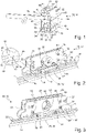
- the 11 shows the actuating mechanism 10 according to the invention in its entirety from the outside.
- the actuating gear 10 is housed in a housing 12 which has a faceplate 14 that is essentially U-shaped in cross section (see also the 10 ) and two side walls 16, which extend in continuation of the two flanges 18 of the faceplate 14.
- the side walls 16 are connected to the flanges 18 of the faceplate 14 via respective Guide plates 20 connected, which flank the inner sides of the side walls 16 and the inner sides of the flanges 18 partially.
- the guide plates 20 are connected to the flanges 18 via bolt connections 22 and to the side walls 16 via bolt connections 22 , so that the side walls 16 are attached indirectly to the flanges 18 of the faceplate 14 via the guide plates 20 .
- the faceplate 14 takes on a translationally displaceable connecting rod 26 within the faceplate 14, which is in direct contact with the web 24 of the faceplate 14 connecting the two flanges 18.
- the connecting rod 26 can be coupled in a drivingly effective manner to an actuator such as a lifting element for raising and lowering a lifting and sliding element.
- the faceplate 14 accommodates in its interior a translationally displaceable transmission element 28 or a connecting rod 28 which is located on the opposite side of the connecting rod 24 to the connecting rod 26 in contact with it.
- the faceplate 14 accommodates in its interior a bolt 30 that is essentially double-T-shaped in cross section, by means of which the connecting rod 26 can be selectively coupled to the transmission element 28 or decoupled from it.
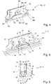
- the bolt 30 is transverse to the longitudinal extent of the drive rod 28 between a locking position (e.g 6 ), in which the drive rod 26 is drivingly coupled to the transmission element 28, and an unlocked position (see, for example 9 , 10 ) movable, in which the drive rod 26 is decoupled from the transmission element 28.
- the bolt 30 has a web 32, at the free end of which a flange 34 is formed which extends perpendicularly to the web 32 and which, in the locking position, has a positive fit in a first shot 36 engages, which is formed longitudinally extending in the connecting rod 26, see for example the Figures 4 and 6 .
- the transmission element 28 has a second receptacle 38 which extends longitudinally in the transmission element 28 and in which the flange 34 also engages in a form-fitting manner when the bolt 30 is in the locking position, see again FIG Figures 4, 6 .
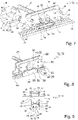
- the two receptacles 36, 38 are delimited in the longitudinal direction by shoulder sections 40, which are oriented transversely to the longitudinal extension of the drive rod 26 and the transmission element 28, see for example Figures 4, 5 , 7, 8 and in particular the enlarged details of the figs 2 and 7 , in which these shoulder sections 40 can be seen.
- the flange 34 is thus caught in the locking position of the bolt 30 in the longitudinal direction of the two receptacles 36, 38 or is positively secured therein, with the result that a movement triggered by an electric motor coupled to the transmission element 28 is transmitted via the bolt 30 to the drive rod 26 is transmitted.
- an opening 42 is defined by the shoulder portions 40 of the second receptacle 38 of the transmission element 28, the clear width of which is less than the width of the web 32 of the bolt 30.
- the web 32 In the unlocked position, as for example in the 9 and 10 As can be seen, the web 32 can thus be pushed out of the second receptacle 38 through the respective opening 42 into an adjoining longitudinal slot 44 which is formed in the transmission element 28 .
- the positive connection between the flange 34 and the transmission element 28 is thus eliminated.
- the bolt 30 has a toothed rack section 46 at the end opposite the flange 34, which meshes with external teeth 48 which are formed on the outer circumference of an input shaft designed as a square nut 50 is formed.
- the toothed rack section 46 and thus the bolt 30 can be moved in a translatory manner in its entirety in its unlocked position, which, due to the form fit between the flange 34 of the bolt 30 and the connecting rod 26, has the result that the connecting rod 26 in the Unlocked position of the bolt 30 can be moved translationally by rotation of the input shaft 50.
- the input shaft 50 is movably mounted transversely or perpendicularly to the longitudinal extension of the connecting rod 26 so that it is coupled to the locking bar 30 in a drivingly active manner and via this to the connecting rod 26 in a drivingly effective manner, regardless of the position of the bolt 30 . Since the input shaft 50 can always be moved together with the bolt 30 transversely to the longitudinal extent of the drive rod 26, the unit of input shaft 50 and bolt 30 can also be referred to as a bolt assembly, so that the locking position and the unlocked position of the bolt 30 are on the bolt assembly relates in its entirety.
- the bolt 30 is moved in the direction of its locked position or in Direction of the input shaft 50 biased.
- the free ends of the leaf springs 52 form cylindrical receptacles 54, which are each pushed onto the pin 56 provided on the toothed rack section 46 of the bolt 30.
- the leaf springs 52 are thus supported on the one hand on the toothed rack section 46 and on the other hand on the transmission element 28 and/or on flange sections 58 which are formed on the inside of the flanges 18 of the faceplate 14 .
- the bolt 30 is thus always urged by the leaf springs 52 in the direction of the input shaft 50 and thus in the direction of its locking position.
- the leaf springs 52 can be guided along the flange sections 58 like the curves of a carriage, so that the movement of the bolt 30 in the longitudinal direction of the connecting rod is not impaired by the leaf springs 52 .
- the input shaft 50 is movably mounted transversely to the longitudinal extent of the drive rod 26 .
- the two opposite ends of the input shaft 50 engage in respective circular openings 60 or through them, which are formed in bearing plates 62 which are guided displaceably on the two guide plates 20 transversely to the longitudinal extension of the drive rod 26 .
- four guide pins 64 are formed on the outside of the respective bearing plate 62, which engage in pairs in two guide slots 66, which are formed in the respective guide plate 20, cf 3 .
- the bearing plates 62 can thus not tilt when they move transversely to the longitudinal extension of the connecting rod 26 together with the input shaft 50 mounted on it.
- each guide plate 20 according to 3 a slot 68 is formed, into which the respective free end of the input shaft 50 engages.
- the input shaft 50 is thus, on the one hand, rotatably mounted in or on the bearing plates 62 and, on the other hand, is displaceably guided in the elongated holes 68 of the guide plates 20 .
- circular bores 72 are formed in the two side walls 16, through which the square mandrel 70 can be inserted into the input shaft 50, see, for example, 1 .
- the latch assembly and in particular the input shaft 50 is biased towards the locking position by the action of the leaf springs 52, the input shaft 50 is offset in the locking position relative to the bores 72 and is thus not coaxially aligned with the bores 72, see again the 1 .
- the square mandrel 70 is now inserted through one of the bores 72 into the input shaft 50 for emergency unlocking, the result is that the input shaft 50 and thus the entire bolt assembly is deflected into the unlocked position in which the input shaft 50 with the bores 72 in the side walls 16 is aligned or coaxially aligned with these, see also the figs 9 and 10 .
- the square mandrel 70 By inserting the square mandrel 70 into the input shaft 50, this is thus automatically deflected into its unlocked position, whereupon the drive rod 26 can be displaced by rotating the square mandrel 70 to implement the emergency unlocking function.
- this mode of operation presupposes that the cross-sectional diagonal of the square mandrel 70 essentially corresponds to the diameter of the bores 72 or is slightly smaller than the diameter of these bores 72 .
- the bolt 30 is moved back again by rotating the square mandrel 70, so that the flange 34 of the bolt 30 can again positively engage in the second receptacle 38 of the transmission element 38.
- the latch assembly and particularly the latch 30 is prevented by the square mandrel 70 from falling under the biasing action of the leaf springs 52 to move back to its locked position.
- the square nut of the input shaft 50 has a central first square recess 74 and on both sides of this a second square recess 76, the side length of the first square recess 74 being smaller than that of the second square recess 76.
- the second square recesses 76 are therefore larger than the first square recess 74.
- the bolt 38 is automatically moved by the leaf springs 52 into its locking position, in which the flange 34 is again received in a form-fitting manner by the second receptacle 38 of the transmission element 28 .
- the transmission element 28 is thus again coupled to the drive rod 26 via the latch 30, so that after the repair or replacement of the electric motor has been completed, the drive rod 26 can be motor-driven again.
Landscapes
- Engineering & Computer Science (AREA)
- Mechanical Engineering (AREA)
- Lock And Its Accessories (AREA)
Applications Claiming Priority (1)
| Application Number | Priority Date | Filing Date | Title |
|---|---|---|---|
| DE102021106475.9A DE102021106475A1 (de) | 2021-03-17 | 2021-03-17 | Betätigungsgetriebe für ein fenster oder eine tür mit notentriegelungsfunktion |
Publications (2)
| Publication Number | Publication Date |
|---|---|
| EP4060152A1 true EP4060152A1 (fr) | 2022-09-21 |
| EP4060152B1 EP4060152B1 (fr) | 2024-01-24 |
Family
ID=80685059
Family Applications (1)
| Application Number | Title | Priority Date | Filing Date |
|---|---|---|---|
| EP22161094.2A Active EP4060152B1 (fr) | 2021-03-17 | 2022-03-09 | Mécanisme d'actionnement pour une fenêtre ou une porte à fonction de déverrouillage d'urgence |
Country Status (2)
| Country | Link |
|---|---|
| EP (1) | EP4060152B1 (fr) |
| DE (1) | DE102021106475A1 (fr) |
Citations (3)
| Publication number | Priority date | Publication date | Assignee | Title |
|---|---|---|---|---|
| DE10150012A1 (de) * | 2001-10-11 | 2003-04-17 | Siegenia Aubi Kg | Fenster oder Tür mit einem Treibstangenbeschlag |
| EP2818616A2 (fr) * | 2013-06-27 | 2014-12-31 | GEZE GmbH | Installation de porte |
| DE102018119986A1 (de) | 2018-08-16 | 2020-02-20 | Maco Technologie Gmbh | Betätigungsgetriebe zum verschieben einer treibstange eines fensters oder einer tür |
Family Cites Families (6)
| Publication number | Priority date | Publication date | Assignee | Title |
|---|---|---|---|---|
| ATE66713T1 (de) | 1986-11-27 | 1991-09-15 | Abs Brandschutz | Verschliessvorrichtung zum verschliessen von oeffnungen in schutzraeumen. |
| DE102005000191A1 (de) | 2005-12-20 | 2007-06-21 | Siegenia-Aubi Kg | Treibstangengetriebe |
| PL1865130T3 (pl) | 2006-03-22 | 2010-07-30 | Roto Frank Ag | Układ odryglowujący okna, drzwi lub tym podobnych |
| DE102009020939A1 (de) | 2009-01-12 | 2010-07-22 | Hautau Gmbh | Zungengetriebe zum Verriegeln oder Entriegeln eines Schiebeflügels |
| DE202013004804U1 (de) | 2013-05-24 | 2013-06-27 | Siegenia-Aubi Kg | Vorrichtung zum Verriegeln oder Entriegeln eines Schiebeflügels |
| DE102014112122B4 (de) | 2014-08-25 | 2018-12-20 | Engeltech Gmbh Österreich | Verfahren zum Sperren und Freigeben eines Türblatts und Türanordnung |
-
2021
- 2021-03-17 DE DE102021106475.9A patent/DE102021106475A1/de active Pending
-
2022
- 2022-03-09 EP EP22161094.2A patent/EP4060152B1/fr active Active
Patent Citations (3)
| Publication number | Priority date | Publication date | Assignee | Title |
|---|---|---|---|---|
| DE10150012A1 (de) * | 2001-10-11 | 2003-04-17 | Siegenia Aubi Kg | Fenster oder Tür mit einem Treibstangenbeschlag |
| EP2818616A2 (fr) * | 2013-06-27 | 2014-12-31 | GEZE GmbH | Installation de porte |
| DE102018119986A1 (de) | 2018-08-16 | 2020-02-20 | Maco Technologie Gmbh | Betätigungsgetriebe zum verschieben einer treibstange eines fensters oder einer tür |
Also Published As
| Publication number | Publication date |
|---|---|
| DE102021106475A1 (de) | 2022-09-22 |
| EP4060152B1 (fr) | 2024-01-24 |
Similar Documents
| Publication | Publication Date | Title |
|---|---|---|
| EP0641910B1 (fr) | Engrenage de crémone d'une fenêtre ou porte. | |
| EP0156379B1 (fr) | Tiroir-caisse pour une caisse enregistreuse | |
| EP4438836B1 (fr) | Système de fermeture et porte ou fenêtre dotée d'un tel système de fermeture | |
| DE4321099A1 (de) | Belüftungseinrichtung für Fenster oder Türen | |
| EP4060152B1 (fr) | Mécanisme d'actionnement pour une fenêtre ou une porte à fonction de déverrouillage d'urgence | |
| EP3921495B1 (fr) | Dispositif de transmission d'actionnement pour un élément levant et coulissant avec levier d'arrêt et élément levant et coulissant avec un tel dispositif | |
| EP3611317B1 (fr) | Mécanisme de commande destiné au déplacement d'une barre d'entrainement d'une fenêtre ou d'une porte | |
| EP4146888A1 (fr) | Ensemble charnière à actionnement commun | |
| EP1103684A1 (fr) | Crémone-serrure pour fenêtre à deux battants | |
| EP1739257A1 (fr) | Serrure | |
| DE102024203222B3 (de) | Beschlaganordnung für ein Fenster, eine Tür oder dergleichen zur Betätigung einer Feststellbremse | |
| EP4575152A1 (fr) | Contre-boîte | |
| EP4386165B1 (fr) | Dispositif d'assistance à l'ouverture d'un élément coulissant de levage | |
| EP3299559B1 (fr) | Dispositif de verrouillage pour une fenêtre | |
| EP1936078A2 (fr) | Garniture de fermeture antipanique | |
| EP4726153A1 (fr) | Unité d'actionnement pour serrure antipanique et serrure antipanique dotée d'une telle unité d'actionnement | |
| EP4606978A1 (fr) | Dispositif de fermeture | |
| EP4253707A1 (fr) | Mécanisme d'actionnement autobloquant pour un battant relevable et coulissant et battant relevable doté d'un tel mécanisme d'actionnement | |
| EP4534782A1 (fr) | Serrure motorisée avec protection contre les surcharges | |
| EP0595289B1 (fr) | Dispositif central de retenue pour armoire avec des tiroirs à rail | |
| DE202005005121U1 (de) | Treibstangenantrieb | |
| DE102022117895A1 (de) | Beschlaganordnung zum verriegeln eines verschiebbaren flügels | |
| AT14921U1 (de) | Schloss | |
| WO2025061778A1 (fr) | Fermeture à tendeur | |
| EP4650553A1 (fr) | Ferrure de fenêtre ou de porte |
Legal Events
| Date | Code | Title | Description |
|---|---|---|---|
| PUAI | Public reference made under article 153(3) epc to a published international application that has entered the european phase |
Free format text: ORIGINAL CODE: 0009012 |
|
| STAA | Information on the status of an ep patent application or granted ep patent |
Free format text: STATUS: THE APPLICATION HAS BEEN PUBLISHED |
|
| AK | Designated contracting states |
Kind code of ref document: A1 Designated state(s): AL AT BE BG CH CY CZ DE DK EE ES FI FR GB GR HR HU IE IS IT LI LT LU LV MC MK MT NL NO PL PT RO RS SE SI SK SM TR |
|
| STAA | Information on the status of an ep patent application or granted ep patent |
Free format text: STATUS: REQUEST FOR EXAMINATION WAS MADE |
|
| 17P | Request for examination filed |
Effective date: 20230307 |
|
| RBV | Designated contracting states (corrected) |
Designated state(s): AL AT BE BG CH CY CZ DE DK EE ES FI FR GB GR HR HU IE IS IT LI LT LU LV MC MK MT NL NO PL PT RO RS SE SI SK SM TR |
|
| RIC1 | Information provided on ipc code assigned before grant |
Ipc: E05B 47/00 20060101ALN20230830BHEP Ipc: E05C 9/20 20060101ALI20230830BHEP Ipc: E05D 15/56 20060101ALI20230830BHEP Ipc: E05B 17/00 20060101ALI20230830BHEP Ipc: E05B 15/00 20060101ALI20230830BHEP Ipc: E05C 9/12 20060101AFI20230830BHEP |
|
| GRAP | Despatch of communication of intention to grant a patent |
Free format text: ORIGINAL CODE: EPIDOSNIGR1 |
|
| STAA | Information on the status of an ep patent application or granted ep patent |
Free format text: STATUS: GRANT OF PATENT IS INTENDED |
|
| INTG | Intention to grant announced |
Effective date: 20231019 |
|
| GRAS | Grant fee paid |
Free format text: ORIGINAL CODE: EPIDOSNIGR3 |
|
| P01 | Opt-out of the competence of the unified patent court (upc) registered |
Effective date: 20231102 |
|
| GRAA | (expected) grant |
Free format text: ORIGINAL CODE: 0009210 |
|
| STAA | Information on the status of an ep patent application or granted ep patent |
Free format text: STATUS: THE PATENT HAS BEEN GRANTED |
|
| AK | Designated contracting states |
Kind code of ref document: B1 Designated state(s): AL AT BE BG CH CY CZ DE DK EE ES FI FR GB GR HR HU IE IS IT LI LT LU LV MC MK MT NL NO PL PT RO RS SE SI SK SM TR |
|
| REG | Reference to a national code |
Ref country code: GB Ref legal event code: FG4D Free format text: NOT ENGLISH |
|
| REG | Reference to a national code |
Ref country code: CH Ref legal event code: EP |
|
| REG | Reference to a national code |
Ref country code: IE Ref legal event code: FG4D Free format text: LANGUAGE OF EP DOCUMENT: GERMAN |
|
| REG | Reference to a national code |
Ref country code: DE Ref legal event code: R096 Ref document number: 502022000410 Country of ref document: DE |
|
| REG | Reference to a national code |
Ref country code: LT Ref legal event code: MG9D |
|
| REG | Reference to a national code |
Ref country code: NL Ref legal event code: MP Effective date: 20240124 |
|
| PG25 | Lapsed in a contracting state [announced via postgrant information from national office to epo] |
Ref country code: NL Free format text: LAPSE BECAUSE OF FAILURE TO SUBMIT A TRANSLATION OF THE DESCRIPTION OR TO PAY THE FEE WITHIN THE PRESCRIBED TIME-LIMIT Effective date: 20240124 |
|
| PG25 | Lapsed in a contracting state [announced via postgrant information from national office to epo] |
Ref country code: NL Free format text: LAPSE BECAUSE OF FAILURE TO SUBMIT A TRANSLATION OF THE DESCRIPTION OR TO PAY THE FEE WITHIN THE PRESCRIBED TIME-LIMIT Effective date: 20240124 |
|
| PG25 | Lapsed in a contracting state [announced via postgrant information from national office to epo] |
Ref country code: IS Free format text: LAPSE BECAUSE OF FAILURE TO SUBMIT A TRANSLATION OF THE DESCRIPTION OR TO PAY THE FEE WITHIN THE PRESCRIBED TIME-LIMIT Effective date: 20240524 |
|
| PG25 | Lapsed in a contracting state [announced via postgrant information from national office to epo] |
Ref country code: LT Free format text: LAPSE BECAUSE OF FAILURE TO SUBMIT A TRANSLATION OF THE DESCRIPTION OR TO PAY THE FEE WITHIN THE PRESCRIBED TIME-LIMIT Effective date: 20240124 |
|
| PG25 | Lapsed in a contracting state [announced via postgrant information from national office to epo] |
Ref country code: GR Free format text: LAPSE BECAUSE OF FAILURE TO SUBMIT A TRANSLATION OF THE DESCRIPTION OR TO PAY THE FEE WITHIN THE PRESCRIBED TIME-LIMIT Effective date: 20240425 |
|
| PG25 | Lapsed in a contracting state [announced via postgrant information from national office to epo] |
Ref country code: HR Free format text: LAPSE BECAUSE OF FAILURE TO SUBMIT A TRANSLATION OF THE DESCRIPTION OR TO PAY THE FEE WITHIN THE PRESCRIBED TIME-LIMIT Effective date: 20240124 Ref country code: RS Free format text: LAPSE BECAUSE OF FAILURE TO SUBMIT A TRANSLATION OF THE DESCRIPTION OR TO PAY THE FEE WITHIN THE PRESCRIBED TIME-LIMIT Effective date: 20240424 |
|
| PG25 | Lapsed in a contracting state [announced via postgrant information from national office to epo] |
Ref country code: ES Free format text: LAPSE BECAUSE OF FAILURE TO SUBMIT A TRANSLATION OF THE DESCRIPTION OR TO PAY THE FEE WITHIN THE PRESCRIBED TIME-LIMIT Effective date: 20240124 |
|
| PG25 | Lapsed in a contracting state [announced via postgrant information from national office to epo] |
Ref country code: RS Free format text: LAPSE BECAUSE OF FAILURE TO SUBMIT A TRANSLATION OF THE DESCRIPTION OR TO PAY THE FEE WITHIN THE PRESCRIBED TIME-LIMIT Effective date: 20240424 Ref country code: NO Free format text: LAPSE BECAUSE OF FAILURE TO SUBMIT A TRANSLATION OF THE DESCRIPTION OR TO PAY THE FEE WITHIN THE PRESCRIBED TIME-LIMIT Effective date: 20240424 Ref country code: LT Free format text: LAPSE BECAUSE OF FAILURE TO SUBMIT A TRANSLATION OF THE DESCRIPTION OR TO PAY THE FEE WITHIN THE PRESCRIBED TIME-LIMIT Effective date: 20240124 Ref country code: IS Free format text: LAPSE BECAUSE OF FAILURE TO SUBMIT A TRANSLATION OF THE DESCRIPTION OR TO PAY THE FEE WITHIN THE PRESCRIBED TIME-LIMIT Effective date: 20240524 Ref country code: HR Free format text: LAPSE BECAUSE OF FAILURE TO SUBMIT A TRANSLATION OF THE DESCRIPTION OR TO PAY THE FEE WITHIN THE PRESCRIBED TIME-LIMIT Effective date: 20240124 Ref country code: GR Free format text: LAPSE BECAUSE OF FAILURE TO SUBMIT A TRANSLATION OF THE DESCRIPTION OR TO PAY THE FEE WITHIN THE PRESCRIBED TIME-LIMIT Effective date: 20240425 Ref country code: FI Free format text: LAPSE BECAUSE OF FAILURE TO SUBMIT A TRANSLATION OF THE DESCRIPTION OR TO PAY THE FEE WITHIN THE PRESCRIBED TIME-LIMIT Effective date: 20240124 Ref country code: ES Free format text: LAPSE BECAUSE OF FAILURE TO SUBMIT A TRANSLATION OF THE DESCRIPTION OR TO PAY THE FEE WITHIN THE PRESCRIBED TIME-LIMIT Effective date: 20240124 Ref country code: BG Free format text: LAPSE BECAUSE OF FAILURE TO SUBMIT A TRANSLATION OF THE DESCRIPTION OR TO PAY THE FEE WITHIN THE PRESCRIBED TIME-LIMIT Effective date: 20240124 |
|
| PG25 | Lapsed in a contracting state [announced via postgrant information from national office to epo] |
Ref country code: PL Free format text: LAPSE BECAUSE OF FAILURE TO SUBMIT A TRANSLATION OF THE DESCRIPTION OR TO PAY THE FEE WITHIN THE PRESCRIBED TIME-LIMIT Effective date: 20240124 Ref country code: PT Free format text: LAPSE BECAUSE OF FAILURE TO SUBMIT A TRANSLATION OF THE DESCRIPTION OR TO PAY THE FEE WITHIN THE PRESCRIBED TIME-LIMIT Effective date: 20240524 |
|
| PG25 | Lapsed in a contracting state [announced via postgrant information from national office to epo] |
Ref country code: SE Free format text: LAPSE BECAUSE OF FAILURE TO SUBMIT A TRANSLATION OF THE DESCRIPTION OR TO PAY THE FEE WITHIN THE PRESCRIBED TIME-LIMIT Effective date: 20240124 Ref country code: PT Free format text: LAPSE BECAUSE OF FAILURE TO SUBMIT A TRANSLATION OF THE DESCRIPTION OR TO PAY THE FEE WITHIN THE PRESCRIBED TIME-LIMIT Effective date: 20240524 Ref country code: PL Free format text: LAPSE BECAUSE OF FAILURE TO SUBMIT A TRANSLATION OF THE DESCRIPTION OR TO PAY THE FEE WITHIN THE PRESCRIBED TIME-LIMIT Effective date: 20240124 Ref country code: LV Free format text: LAPSE BECAUSE OF FAILURE TO SUBMIT A TRANSLATION OF THE DESCRIPTION OR TO PAY THE FEE WITHIN THE PRESCRIBED TIME-LIMIT Effective date: 20240124 |
|
| PG25 | Lapsed in a contracting state [announced via postgrant information from national office to epo] |
Ref country code: DK Free format text: LAPSE BECAUSE OF FAILURE TO SUBMIT A TRANSLATION OF THE DESCRIPTION OR TO PAY THE FEE WITHIN THE PRESCRIBED TIME-LIMIT Effective date: 20240124 |
|
| PG25 | Lapsed in a contracting state [announced via postgrant information from national office to epo] |
Ref country code: SM Free format text: LAPSE BECAUSE OF FAILURE TO SUBMIT A TRANSLATION OF THE DESCRIPTION OR TO PAY THE FEE WITHIN THE PRESCRIBED TIME-LIMIT Effective date: 20240124 |
|
| PG25 | Lapsed in a contracting state [announced via postgrant information from national office to epo] |
Ref country code: EE Free format text: LAPSE BECAUSE OF FAILURE TO SUBMIT A TRANSLATION OF THE DESCRIPTION OR TO PAY THE FEE WITHIN THE PRESCRIBED TIME-LIMIT Effective date: 20240124 Ref country code: CZ Free format text: LAPSE BECAUSE OF FAILURE TO SUBMIT A TRANSLATION OF THE DESCRIPTION OR TO PAY THE FEE WITHIN THE PRESCRIBED TIME-LIMIT Effective date: 20240124 |
|
| REG | Reference to a national code |
Ref country code: DE Ref legal event code: R097 Ref document number: 502022000410 Country of ref document: DE |
|
| PG25 | Lapsed in a contracting state [announced via postgrant information from national office to epo] |
Ref country code: SK Free format text: LAPSE BECAUSE OF FAILURE TO SUBMIT A TRANSLATION OF THE DESCRIPTION OR TO PAY THE FEE WITHIN THE PRESCRIBED TIME-LIMIT Effective date: 20240124 |
|
| PG25 | Lapsed in a contracting state [announced via postgrant information from national office to epo] |
Ref country code: SM Free format text: LAPSE BECAUSE OF FAILURE TO SUBMIT A TRANSLATION OF THE DESCRIPTION OR TO PAY THE FEE WITHIN THE PRESCRIBED TIME-LIMIT Effective date: 20240124 Ref country code: SK Free format text: LAPSE BECAUSE OF FAILURE TO SUBMIT A TRANSLATION OF THE DESCRIPTION OR TO PAY THE FEE WITHIN THE PRESCRIBED TIME-LIMIT Effective date: 20240124 Ref country code: EE Free format text: LAPSE BECAUSE OF FAILURE TO SUBMIT A TRANSLATION OF THE DESCRIPTION OR TO PAY THE FEE WITHIN THE PRESCRIBED TIME-LIMIT Effective date: 20240124 Ref country code: DK Free format text: LAPSE BECAUSE OF FAILURE TO SUBMIT A TRANSLATION OF THE DESCRIPTION OR TO PAY THE FEE WITHIN THE PRESCRIBED TIME-LIMIT Effective date: 20240124 Ref country code: CZ Free format text: LAPSE BECAUSE OF FAILURE TO SUBMIT A TRANSLATION OF THE DESCRIPTION OR TO PAY THE FEE WITHIN THE PRESCRIBED TIME-LIMIT Effective date: 20240124 |
|
| PG25 | Lapsed in a contracting state [announced via postgrant information from national office to epo] |
Ref country code: LU Free format text: LAPSE BECAUSE OF NON-PAYMENT OF DUE FEES Effective date: 20240309 |
|
| PG25 | Lapsed in a contracting state [announced via postgrant information from national office to epo] |
Ref country code: MC Free format text: LAPSE BECAUSE OF FAILURE TO SUBMIT A TRANSLATION OF THE DESCRIPTION OR TO PAY THE FEE WITHIN THE PRESCRIBED TIME-LIMIT Effective date: 20240124 |
|
| PG25 | Lapsed in a contracting state [announced via postgrant information from national office to epo] |
Ref country code: MC Free format text: LAPSE BECAUSE OF FAILURE TO SUBMIT A TRANSLATION OF THE DESCRIPTION OR TO PAY THE FEE WITHIN THE PRESCRIBED TIME-LIMIT Effective date: 20240124 Ref country code: LU Free format text: LAPSE BECAUSE OF NON-PAYMENT OF DUE FEES Effective date: 20240309 |
|
| PLBE | No opposition filed within time limit |
Free format text: ORIGINAL CODE: 0009261 |
|
| STAA | Information on the status of an ep patent application or granted ep patent |
Free format text: STATUS: NO OPPOSITION FILED WITHIN TIME LIMIT |
|
| REG | Reference to a national code |
Ref country code: BE Ref legal event code: MM Effective date: 20240331 |
|
| 26N | No opposition filed |
Effective date: 20241025 |
|
| PG25 | Lapsed in a contracting state [announced via postgrant information from national office to epo] |
Ref country code: BE Free format text: LAPSE BECAUSE OF NON-PAYMENT OF DUE FEES Effective date: 20240331 |
|
| PG25 | Lapsed in a contracting state [announced via postgrant information from national office to epo] |
Ref country code: IE Free format text: LAPSE BECAUSE OF NON-PAYMENT OF DUE FEES Effective date: 20240309 |
|
| PG25 | Lapsed in a contracting state [announced via postgrant information from national office to epo] |
Ref country code: IE Free format text: LAPSE BECAUSE OF NON-PAYMENT OF DUE FEES Effective date: 20240309 Ref country code: BE Free format text: LAPSE BECAUSE OF NON-PAYMENT OF DUE FEES Effective date: 20240331 |
|
| PG25 | Lapsed in a contracting state [announced via postgrant information from national office to epo] |
Ref country code: SI Free format text: LAPSE BECAUSE OF FAILURE TO SUBMIT A TRANSLATION OF THE DESCRIPTION OR TO PAY THE FEE WITHIN THE PRESCRIBED TIME-LIMIT Effective date: 20240124 |
|
| PG25 | Lapsed in a contracting state [announced via postgrant information from national office to epo] |
Ref country code: RO Free format text: LAPSE BECAUSE OF FAILURE TO SUBMIT A TRANSLATION OF THE DESCRIPTION OR TO PAY THE FEE WITHIN THE PRESCRIBED TIME-LIMIT Effective date: 20240124 |
|
| PG25 | Lapsed in a contracting state [announced via postgrant information from national office to epo] |
Ref country code: CY Free format text: LAPSE BECAUSE OF FAILURE TO SUBMIT A TRANSLATION OF THE DESCRIPTION OR TO PAY THE FEE WITHIN THE PRESCRIBED TIME-LIMIT; INVALID AB INITIO Effective date: 20220309 |
|
| REG | Reference to a national code |
Ref country code: CH Ref legal event code: H13 Free format text: ST27 STATUS EVENT CODE: U-0-0-H10-H13 (AS PROVIDED BY THE NATIONAL OFFICE) Effective date: 20251023 |
|
| PG25 | Lapsed in a contracting state [announced via postgrant information from national office to epo] |
Ref country code: TR Free format text: LAPSE BECAUSE OF FAILURE TO SUBMIT A TRANSLATION OF THE DESCRIPTION OR TO PAY THE FEE WITHIN THE PRESCRIBED TIME-LIMIT Effective date: 20240124 |
|
| PG25 | Lapsed in a contracting state [announced via postgrant information from national office to epo] |
Ref country code: CH Free format text: LAPSE BECAUSE OF NON-PAYMENT OF DUE FEES Effective date: 20250331 |
|
| PGFP | Annual fee paid to national office [announced via postgrant information from national office to epo] |
Ref country code: DE Payment date: 20260319 Year of fee payment: 5 |
|
| PGFP | Annual fee paid to national office [announced via postgrant information from national office to epo] |
Ref country code: AT Payment date: 20260301 Year of fee payment: 5 |
|
| PGFP | Annual fee paid to national office [announced via postgrant information from national office to epo] |
Ref country code: IT Payment date: 20260324 Year of fee payment: 5 |
|
| PGFP | Annual fee paid to national office [announced via postgrant information from national office to epo] |
Ref country code: FR Payment date: 20260323 Year of fee payment: 5 |