EP4062020B1 - Support d'angle - Google Patents
Support d'angle Download PDFInfo
- Publication number
- EP4062020B1 EP4062020B1 EP20808103.4A EP20808103A EP4062020B1 EP 4062020 B1 EP4062020 B1 EP 4062020B1 EP 20808103 A EP20808103 A EP 20808103A EP 4062020 B1 EP4062020 B1 EP 4062020B1
- Authority
- EP
- European Patent Office
- Prior art keywords
- lift
- lift cable
- switch
- motor
- vertical moving
- Prior art date
- Legal status (The legal status is an assumption and is not a legal conclusion. Google has not performed a legal analysis and makes no representation as to the accuracy of the status listed.)
- Active
Links
Images


Classifications
-
- E—FIXED CONSTRUCTIONS
- E05—LOCKS; KEYS; WINDOW OR DOOR FITTINGS; SAFES
- E05D—HINGES OR SUSPENSION DEVICES FOR DOORS, WINDOWS OR WINGS
- E05D13/00—Accessories for sliding or lifting wings, e.g. pulleys, safety catches
- E05D13/003—Anti-dropping devices
-
- E—FIXED CONSTRUCTIONS
- E05—LOCKS; KEYS; WINDOW OR DOOR FITTINGS; SAFES
- E05D—HINGES OR SUSPENSION DEVICES FOR DOORS, WINDOWS OR WINGS
- E05D13/00—Accessories for sliding or lifting wings, e.g. pulleys, safety catches
- E05D13/003—Anti-dropping devices
- E05D13/006—Anti-dropping devices fixed to the wing, i.e. safety catches
-
- E—FIXED CONSTRUCTIONS
- E05—LOCKS; KEYS; WINDOW OR DOOR FITTINGS; SAFES
- E05F—DEVICES FOR MOVING WINGS INTO OPEN OR CLOSED POSITION; CHECKS FOR WINGS; WING FITTINGS NOT OTHERWISE PROVIDED FOR, CONCERNED WITH THE FUNCTIONING OF THE WING
- E05F15/00—Power-operated mechanisms for wings
- E05F15/60—Power-operated mechanisms for wings using electrical actuators
- E05F15/603—Power-operated mechanisms for wings using electrical actuators using rotary electromotors
- E05F15/665—Power-operated mechanisms for wings using electrical actuators using rotary electromotors for vertically-sliding wings
- E05F15/668—Power-operated mechanisms for wings using electrical actuators using rotary electromotors for vertically-sliding wings for overhead wings
- E05F15/681—Power-operated mechanisms for wings using electrical actuators using rotary electromotors for vertically-sliding wings for overhead wings operated by flexible elongated pulling elements, e.g. belts
- E05F15/686—Power-operated mechanisms for wings using electrical actuators using rotary electromotors for vertically-sliding wings for overhead wings operated by flexible elongated pulling elements, e.g. belts by cables or ropes
-
- E—FIXED CONSTRUCTIONS
- E05—LOCKS; KEYS; WINDOW OR DOOR FITTINGS; SAFES
- E05Y—INDEXING SCHEME ASSOCIATED WITH SUBCLASSES E05D AND E05F, RELATING TO CONSTRUCTION ELEMENTS, ELECTRIC CONTROL, POWER SUPPLY, POWER SIGNAL OR TRANSMISSION, USER INTERFACES, MOUNTING OR COUPLING, DETAILS, ACCESSORIES, AUXILIARY OPERATIONS NOT OTHERWISE PROVIDED FOR, APPLICATION THEREOF
- E05Y2201/00—Constructional elements; Accessories therefor
- E05Y2201/60—Suspension or transmission members; Accessories therefor
- E05Y2201/622—Suspension or transmission members elements
- E05Y2201/658—Members cooperating with flexible elongated pulling elements
- E05Y2201/672—Tensioners, tension sensors
-
- E—FIXED CONSTRUCTIONS
- E05—LOCKS; KEYS; WINDOW OR DOOR FITTINGS; SAFES
- E05Y—INDEXING SCHEME ASSOCIATED WITH SUBCLASSES E05D AND E05F, RELATING TO CONSTRUCTION ELEMENTS, ELECTRIC CONTROL, POWER SUPPLY, POWER SIGNAL OR TRANSMISSION, USER INTERFACES, MOUNTING OR COUPLING, DETAILS, ACCESSORIES, AUXILIARY OPERATIONS NOT OTHERWISE PROVIDED FOR, APPLICATION THEREOF
- E05Y2400/00—Electronic control; Electrical power; Power supply; Power or signal transmission; User interfaces
- E05Y2400/10—Electronic control
- E05Y2400/44—Sensors not directly associated with the wing movement
- E05Y2400/445—Switches
-
- E—FIXED CONSTRUCTIONS
- E05—LOCKS; KEYS; WINDOW OR DOOR FITTINGS; SAFES
- E05Y—INDEXING SCHEME ASSOCIATED WITH SUBCLASSES E05D AND E05F, RELATING TO CONSTRUCTION ELEMENTS, ELECTRIC CONTROL, POWER SUPPLY, POWER SIGNAL OR TRANSMISSION, USER INTERFACES, MOUNTING OR COUPLING, DETAILS, ACCESSORIES, AUXILIARY OPERATIONS NOT OTHERWISE PROVIDED FOR, APPLICATION THEREOF
- E05Y2400/00—Electronic control; Electrical power; Power supply; Power or signal transmission; User interfaces
- E05Y2400/10—Electronic control
- E05Y2400/50—Fault detection
- E05Y2400/502—Fault detection of components
-
- E—FIXED CONSTRUCTIONS
- E05—LOCKS; KEYS; WINDOW OR DOOR FITTINGS; SAFES
- E05Y—INDEXING SCHEME ASSOCIATED WITH SUBCLASSES E05D AND E05F, RELATING TO CONSTRUCTION ELEMENTS, ELECTRIC CONTROL, POWER SUPPLY, POWER SIGNAL OR TRANSMISSION, USER INTERFACES, MOUNTING OR COUPLING, DETAILS, ACCESSORIES, AUXILIARY OPERATIONS NOT OTHERWISE PROVIDED FOR, APPLICATION THEREOF
- E05Y2400/00—Electronic control; Electrical power; Power supply; Power or signal transmission; User interfaces
- E05Y2400/10—Electronic control
- E05Y2400/50—Fault detection
- E05Y2400/506—Fault detection of counterbalance
-
- E—FIXED CONSTRUCTIONS
- E05—LOCKS; KEYS; WINDOW OR DOOR FITTINGS; SAFES
- E05Y—INDEXING SCHEME ASSOCIATED WITH SUBCLASSES E05D AND E05F, RELATING TO CONSTRUCTION ELEMENTS, ELECTRIC CONTROL, POWER SUPPLY, POWER SIGNAL OR TRANSMISSION, USER INTERFACES, MOUNTING OR COUPLING, DETAILS, ACCESSORIES, AUXILIARY OPERATIONS NOT OTHERWISE PROVIDED FOR, APPLICATION THEREOF
- E05Y2400/00—Electronic control; Electrical power; Power supply; Power or signal transmission; User interfaces
- E05Y2400/10—Electronic control
- E05Y2400/52—Safety arrangements associated with the wing motor
- E05Y2400/53—Wing impact prevention or reduction
- E05Y2400/54—Obstruction or resistance detection
- E05Y2400/55—Obstruction or resistance detection by using load sensors
- E05Y2400/552—Switches
-
- E—FIXED CONSTRUCTIONS
- E05—LOCKS; KEYS; WINDOW OR DOOR FITTINGS; SAFES
- E05Y—INDEXING SCHEME ASSOCIATED WITH SUBCLASSES E05D AND E05F, RELATING TO CONSTRUCTION ELEMENTS, ELECTRIC CONTROL, POWER SUPPLY, POWER SIGNAL OR TRANSMISSION, USER INTERFACES, MOUNTING OR COUPLING, DETAILS, ACCESSORIES, AUXILIARY OPERATIONS NOT OTHERWISE PROVIDED FOR, APPLICATION THEREOF
- E05Y2600/00—Mounting or coupling arrangements for elements provided for in this subclass
- E05Y2600/60—Mounting or coupling members; Accessories therefor
- E05Y2600/626—Plates or brackets
Definitions
- the present invention relates to vertical moving doors. More specifically, the disclosure relates to a corner bracket as defined in the introductory part of claim 1 and to a vertical moving door system.
- the disclosure also relates to a method, performed by a control device, for stopping a vertical moving door of a vertical moving door system.
- the disclosure relates to a computer program and to a computer-readable medium.
- a corner bracket is adapted to be attached to a vertical moving door and is used to interact with a lift cable for the door.
- One corner bracket may be attached at one side of the door and another corner bracket may be attached at the other side of the door.
- the lift cables interact with each corner bracket and when applying a traction force in the lift cables, the door will move in the vertical direction.
- Cable brake devices are used to brake and stop the movement of a vertical moving door in the event of that the lift cable for moving the vertical moving door breaks or snaps.
- the cable brake device interacts with tracks of the vertical moving door system and the cable brake device could damage the track in the event of the cable brake device being activated and brake the movement of the vertical moving door.
- WO 00/57011 A1 discloses a corner bracket according to the preamble of claim 1 comprising a cable failure device for immobilizing a cable operated door, such as garage doors and the like, in the event of a failure of one of the cables operating.
- EP 0 149 692 A1 discloses a cable transmission to prevent a door from falling down when a cable tear occurs.
- DE 29 17 023 A1 discloses a cable operating mechanism for a pulley motor for a roller shutter.
- EP 2 835 480 A2 discloses a door that comprises a slack cable safety switch, accommodated in a chamber of a lever and an actuating element, which can protrude from a housing opening.
- EP0393489A1 discloses a slack-rope safety device for monitoring the tensile load of a rope assembly for the raising, holding and controlled lowering of a door leaf.
- EP 2 333 230 A1 discloses a hoist mechanism for a vertically movable door.
- a corner bracket for a vertical moving door comprising: a base plate configured to be attached to the door; and a guide path for a lift cable arranged in the base plate; wherein: a switch is arranged in the base plate and configured to be actuated by the lift cable in the event of a breakage of the lift cable. The actuation of the switch is an indication of a lift cable break.
- a control element is arranged in the guide path and configured to be controlled by the lift cable; and wherein: the control element is configured to be pushed by the lift cable to a first position when the lift cable extends into the guide path, the control element is configured to be released by the lift cable to a second position in the event of a breakage of the lift cable, and the control element is configured to actuate the switch when the control element has been moved to the second position.
- the guide path in the base plate is occupied by the lift cable when the lift cable is tensioned and works correctly. In case of a cable break, the lift cable will leave the guide path and simultaneously release the control element and thus actuate the switch.
- control element is a lever, comprising a leaf spring element having a spring force configured to be exceeded by a force from the lift cable when the lever is pushed to the first position.
- the lift cable When the lift cable is tensioned and works correctly, the lift cable will abut against the leaf spring element and push the leaf spring element to the first position. As long the leaf spring element is in the first position, the switch will not be actuated.
- control element is a pin, comprising a helical spring element having a spring force configured to be exceeded by a force from the lift cable when the pin is pushed to the first position.
- the pin comprising a helical spring element is configured to be pushed to the first position by the lift cable, when the lift cable is tensioned and works correctly.
- the guide path comprises an aperture, through which aperture, the control element is configured to extend.
- the switch is arranged in the base plate, and the control element is configured to extend through the aperture.
- the guide path comprises a circular extension.
- the circular extension of the guide path results in that the lift cable smoothly will follow the circular extension and occupy the guide path when the lift cable is tensioned and works correctly.
- the aperture is arranged in the circular extension of the guide path. Since the lift cable smoothly will follow the circular extension of the guide path, the lift cable will abut firmly against the control element, which is configured to extend through the aperture.
- the base plate comprising a fastener element, which is configured to attaching the lift cable to the base plate.
- the weight from the vertical moving door will tension the lift cable when the lift cable is attached to the base plate.
- the switch is an electrical micro switch.
- the micro switch is configured to be arranged in the base plate.
- a vertical moving door system comprising a vertical moving door, at least two lift cables, a motor and at least two corner brackets according to the above, wherein the respective at least two lift cables are connected to the motor and to the at least two corner brackets and wherein the motor is configured to move the vertical moving door by the at least two lift cables between an open and closed position.
- Moving the vertical moving door from the closed to the opened position is accomplished by tensioning the lift cables by the motor and to rolling up the lift cables on cable drums.
- the vertical moving door will move from the opened to the closed position by rolling out the cables from the cable drums by the motor, but still keep the lift cables in a tense position.
- springs may be connected to the vertical moving door and an adjacent wall.
- the switch arranged in the corner brackets is configured to be actuated by the lift cable in the event of a breakage of the lift cable.
- the actuation of the switch is an indication of a lift cable break.
- the motor and the switch in each of the at least two corner brackets are connected to an electric circuit, and wherein the switch is actuated and configured to stop the motor in the event of a breakage of the lift cable, which is connected to the corner bracket comprising the actuated switch.
- the switch is actuated and configured to stop the motor in the event of a breakage of one of the lift cables.
- the door will stop in the event of a breakage of one of the lift cables.
- the electric circuit comprises a control device configured to receive an input signal from the actuated switch, and wherein the control device is configured to stop the motor as a response to the received input signal from the actuated switch.
- a first corner bracket is arranged at a first lower side part of the door, and wherein a second corner bracket is arranged at a second lower side part of the door.
- a method for stopping a vertical moving door of a vertical moving door system, the vertical moving door system comprising: at least two lift cables, a motor and at least two corner brackets according to the above, wherein the respective at least two lift cables are connected to the motor and to the at least two corner brackets and wherein the motor is configured to move the vertical moving door by the at least two lift cables between an open and closed position
- the method comprises the steps of: receiving a signal from the switch in the event of a breakage of the lift cable, and controlling the motor to stop the movement of the vertical moving door.
- the disclosure also relates to a computer program comprising instructions which, when the program is executed by a computer, causes the computer to carry out the method disclosed above.
- the disclosure further relates to a computer-readable medium comprising instructions, which when executed by a computer causes the computer to carry out the method disclosed above.
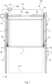
- Fig. 1 shows a vertical moving door system 100.
- the vertical moving door system 100 comprises a vertical moving door 2, a first and a second lift cable 4, 6, a first and second track 8, 10 on each side of the door 2, a motor 12 and first and second corner brackets 14, 16 arranged on each side of the door 2.
- the vertical moving door system 100 is an up and above vertical moving door 2, i.e. the vertical moving door 2 is moveable from a closed position C to an open position O. In the open position O the vertical moving door 2 is positioned in a substantial vertical position above an opening 110 of a wall 120.
- the vertical moving door 2 is according to an aspect a single blade vertical moving door 2.
- the vertical moving door may alternatively be a sectional vertical moving door 2 comprising a number of connected sections (not shown).
- the motor 12 is mounted either directly on the wall 120 or at one of the tracks 8, 10.
- the first and second lift cables 4, 6 is in one end connected to the motor 12 via first and second cable drums 18, 20 and in the other end connected to the vertical moving door 2 via the first and second corner brackets 14, 16. Put in another way, the first and second lift cables 4, 6 are mounted or connected to the first and second corner brackets 14, 16 and the first and second corner brackets 14, 16 are connected or mounted to the vertical moving door 2.
- the motor 5 is configured to wind up and unwind the first and second lift cables 4, 6 on the first and second cable drums 18, 20 and thereby move the vertical moving door 2 between the open and closed position O, C.
- the vertical moving door 2 is moveably connected to the first and second tracks 8, 10.
- the first and second tracks 8, 10 are mounted at the opening 110 and configured to guide the vertical moving door 2 when it is moved between the closed position C and the open position O. Put in another way, the first and second tracks 8, 10 guides the vertical moving door 2 when it is moved from the closed position C to the open position O and from the open positon O to the closed position C.
- the first corner bracket 14 is arranged at a first lower side part 26 of the door 2, and the second corner bracket 16 is arranged at a second lower side part 27 of the door 2.
- the vertical moving door system 100 may comprise two motors 12, positioned at each side of the door 2.
- the first and second tracks 8, 10 may be arranged on each side of the door 2 and positioned at opposite vertical edges of the opening 110.
- the first and second tracks 8, 10 may have a U-, C- or G-shaped cross sectional shape.
- springs 22, 24 may be connected to the vertical moving door 2 and the adjacent wall 120. When moving the door 2 in the direction of the closed position C, the springs 22, 24 may be tensioned.
- the vertical moving door system 100 as such are well known and will thus not be described further in detail herein.
- Each of the first and second corner brackets 14, 16 comprises a switch 28, which is configured to be actuated by the lift cables 4, 6 in the event of a breakage of the lift cables 4, 6.
- the actuation of the switch 28 is an indication of a lift cable break.
- the motor 12 and each switch 28 in the corner brackets 14, 16 are connected to an electric circuit 30.
- the switch 28 is actuated and configured to stop the motor 12 in the event of a breakage of one of the lift cables 4, 6 connected to the corner bracket 14, 16 comprising the actuated switch 28.
- the switch 28 is actuated and configured to stop the motor 12 in the event of a breakage of one of the lift cables 4, 6.
- the electric circuit 30 comprises a control device 200 configured to receive an input signal from the actuated switch 28.
- the control device 200 is configured to send a signal to the motor 12 in order to stop the motor 12 as a response to the received input signal from the actuated switch 28.
- Figures 2 and 3 show schematic cross sectional views along line I - I in fig. 1 , with an unbroken and broken lift cable 4, 6 of a vertical moving door system 100.
- the door 2 is closed and the first lift cable 4 is tensioned and works correctly.
- the first lift cable 4 is in a first end attached to the first corner bracket 14 and in a second end connected to the first cable drum 18.
- the door 2 has moved vertically upwards by the first and second lift cables 14, 16. However, due to failure, the first lift cable 14 has been broken. However, the second lift cable 6 works correctly and prevents the vertical moving door 2 to fall down.
- Stopping the motor 12 and the vertical moving door 2 in the event of a lift cable break will eliminate the risk of that a person or objects in the path of the vertical moving door 2 could be injured or that the vertical moving door system 100 is damaged. Stopping the door 2 in the event of a lift cable break is also an indication for service personnel to replace the broken lift cable 14, 16 with a new lift cable 14, 16.
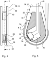
- Figure 4 shows a schematic side view of a corner bracket 14, 16 comprising a base plate 32 configured to be attached to the door ( fig. 1 ) and a guide path 34 for a lift cable arranged in the base plate 32.
- the switch 28 is arranged in the base plate 32 and is configured to be actuated by the lift cable 4, 6 ( fig. 1 ) in the event of a breakage of the lift cable 4, 6.
- a control element 36 is arranged in the guide path 34 and is configured to be controlled by the lift cable 4, 6.
- the guide path 34 comprises an aperture 38, through which aperture 38, the control element 36 is configured to extend.
- the switch 28 is arranged in the base plate 32, and the control element 36 is configured to extend through the aperture 38.
- the base plate 32 comprising a fastener element 40, which is configured to attaching the lift cable 4, 6 to the base plate 32.
- Figure 5 shows a schematic cross sectional view along line II - II in fig. 4 , with an unbroken lift cable 4, 6.
- the lift cable 4, 6 is attached to the fastener element 40.
- the guide path 34 in the base plate 32 is occupied by the lift cable 4, 6 when the lift cable 4, 6 is tensioned and works correctly.
- the control element 36 is configured to be pushed by the lift cable 4, 6 to a first position when the lift cable 4, 6 extends into the guide path 34.
- the control element 36 according to fig. 5 is a lever 36, comprising a leaf spring element 42 having a spring force configured to be exceeded by a force from the lift cable 4, 6 when the lever 36 is pushed to the first position.
- the switch 28 may be an electrical micro switch.
- the switch 28 is arranged in a space 44 of the base plate 32 and adjacent to the aperture 38 in the guide path 34.
- the guide path 34 comprises a circular extension 46.
- the circular extension 46 of the guide path 34 results in that the lift cable 4, 6 smoothly will follow the circular extension 46 and occupy the guide path 34 when the lift cable 4, 6 is tensioned and works correctly.
- the aperture 38 is arranged in the circular extension 46 of the guide path 34. Since the lift cable 4, 6 smoothly will follow the circular extension 46 of the guide path 34, the lift cable 4, 6 will abut firmly against the control element 36, which is configured to extend through the aperture 38.
- Signal cables 48 of the circuit 30 are connected to the switch 28.
- Figure 6 shows a schematic cross sectional view along line II - II in fig. 4 , with a broken lift cable 4, 6.
- the leaf spring element 42 has been released by the lift cable 4, 6 to a second position in the event of a breakage of the lift cable 4, 6.
- the leaf spring element 42 is configured to actuate the switch 28 when the leaf spring element 42 has been moved to the second position.
- the lift cable 4, 6 have left the guide path 34 and simultaneously released the leaf spring element 42 and thus actuated the switch 28.
- signals to the circuit 30 are initiated for stopping the motor 12.
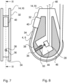
- Figure 7 shows a schematic side view of a corner bracket 14, 16 comprising a base plate 32 configured to be attached to the door 2 ( fig. 1 ) and a guide path 32 for a lift cable arranged in the base plate 32.
- the switch 28 is arranged in the base plate 32 and is configured to be actuated by the lift cable 4, 6 ( fig. 1 ) in the event of a breakage of the lift cable 4, 6.
- a control element 36 is arranged in the guide path 34 and is configured to be controlled by the lift cable 4, 6.
- the guide path 34 comprises an aperture 38, through which aperture 38, the control element 36 is configured to extend.
- the switch 28 is arranged in the base plate 32, and the control element 36 is configured to extend through the aperture 38.
- the base plate 32 comprising a fastener element 40, which is configured to attaching the lift cable 4, 6 to the base plate 32.
- Figure 8 shows a schematic cross sectional view along line III - III in fig. 7 , with an unbroken lift cable 4, 6.
- the lift cable 4, 6 is attached to the fastener element 40.
- the guide path 34 in the base plate 32 is occupied by the lift cable 4, 6 when the lift cable 4, 6 is tensioned and works correctly.
- the control element 36 is configured to be pushed by the lift cable 4, 6 to a first position when the lift cable 4, 6 extends into the guide path 34.
- the control element 36 according to fig. 7 is a pin 36, comprising a helical spring element 50 having a spring force configured to be exceeded by a force from the lift cable 4, 6 when the pin 36 is pushed to the first position.
- the switch 28 may be an electrical micro switch.
- the switch 28 is arranged in a space 44 of the base plate 32.
- the guide path 34 comprises a circular extension 46.
- the circular extension 46 of the guide path 34 results in that the lift cable 4, 6 smoothly will follow the circular extension 46 and occupy the guide path 34 when the lift cable 4, 6 is tensioned and works correctly.
- the aperture 38 is arranged in the circular extension 46 of the guide path 34. Since the lift cable smoothly will follow the circular extension 46 of the guide path 34, the lift cable 4, 6 will abut firmly against the pin 36, which is configured to extend through the aperture 38.
- Signal cables 48 of the circuit 30 are connected to the switch 28.
- Figure 9 shows a schematic cross sectional view along line III - III in fig. 7 , with a broken lift cable 4, 6.
- the pin 36 has been released by the lift cable 4, 6 to a second position in the event of a breakage of the lift cable 4, 6.
- the pin 36 is configured to actuate the switch 28 when the pin 36 has been moved to the second position and released pin 36 on the switch 28.
- the pin 36 has been moved to the second position by the spring element 50.
- the lift cable 4, 6 have left the guide path 34 and simultaneously released the pin 36 and thus actuated the switch 28.
- signals to the circuit 30 is initiated for stopping the motor 12.
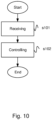
- Figure 10 is illustrates a flow chart of a method, performed by a control device 200, for stopping a vertical moving door 2 of a vertical moving door system 100, the vertical moving door system 100 comprising: at least two lift cables 4, 6, a motor 12 and at least two corner brackets 14, 16, the at least two corner brackets 14, 16 each comprising: a base plate 32 configured to be attached to the door 2; a guide path 34 for a lift cable 4, 6 arranged in the base plate 32; and a switch 28 is arranged in the base plate 32 and configured to be actuated by the lift cable 4, 6 in the event of a breakage of the lift cable 4, 6, wherein the respective at least two lift cables 4, 6 are connected to the motor 12 and to the at least two corner brackets 14, 16 and wherein the motor 12 is configured to move the vertical moving door 2 by the at least two lift cables 4, 6 between an open and closed position O, C.
- the method comprises the steps of: receiving s101 a signal from the switch 28 in the event of a breakage of the lift cable 4, 6, and controlling s102 the motor 12 to stop the movement of the vertical moving door 2.
- FIG 11 is a diagram of a version of a device 500.
- the control device 200 performing the method, may in a version comprise the device 500.
- the device 500 comprises a non-volatile memory 520, a data processing unit 510 and a read/write memory 550.
- the non-volatile memory 520 has a first memory element 530 in which a computer programme, e.g. an operating system, is stored for controlling the function of the device 500.
- the device 500 further comprises a bus controller, a serial communication port, I/O means, an A/D converter, a time and date input and transfer unit, an event counter and an interruption controller (not depicted).
- the non-volatile memory 520 has also a second memory element 540.
- the programme P which comprises routines for performing the safety method.
- the programme P may be stored in an executable form or in a compressed form in a memory 560 and/or in a read/write memory 550.
- the data processing unit 510 is described as performing a certain function, it means that the data processing unit 510 effects a certain part of the programme stored in the memory 560 or a certain part of the programme stored in the read/write memory 550.
- the data processing device 510 can communicate with a data port 599 via a data bus 515.
- the non-volatile memory 520 is intended for communication with the data processing unit 510 via a data bus 512.
- the separate memory 560 is intended to communicate with the data processing unit 510 via a data bus 511.
- the read/write memory 550 is adapted to communicating with the data processing unit 510 via a data bus 514.
- Parts of the methods herein described may be effected by the device 500 by means of the data processing unit 510 which runs the programme stored in the memory 560 or the read/write memory 550. When the device 500 runs the programme, methods herein described are executed.
Landscapes
- Engineering & Computer Science (AREA)
- Mechanical Engineering (AREA)
- Power-Operated Mechanisms For Wings (AREA)
Claims (14)
- Support d'angle (14, 16) pour une porte mobile vertical (2), le support d'angle (14, 16) comprenant :une plaque de base (32) configurée pour être fixée à la porte (2) ;et un chemin de guidage (34) pour un câble de levage (4, 6) agencé dans la plaque de base (32) ; dans lequel :un commutateur (28) est agencé dans la plaque de base (32) et configuré pour être actionné par le câble de levage (4, 6) en cas de rupture du câble de levage (4, 6),dans lequel le commutateur est configuré pour transmettre un signal à un dispositif de commande (200) pour arrêter un moteur (12) en cas de rupture du câble de levage (4, 6), ledit moteur (12) étant configuré pour enrouler et dérouler le câble de levage sur un tambour de câble (18, 20),dans lequel un élément de commande (36) est configuré pour être commandé par le câble de levage (4, 6), dans lequel :l'élément de commande (36) est configuré pour être poussé par le câble de levage (4, 6) vers une première position lorsque le câble de levage (4, 6) s'étend dans le chemin de guidage (34),l'élément de commande (36) est configuré pour être libéré par le câble de levage (4, 6) vers une seconde position en cas de rupture du câble de levage (4, 6), etl'élément de commande (36) est configuré pour actionner le commutateur (28) lorsque l'élément de commande (36) a été déplacé vers la seconde position, caractérisé en ce que l'élément de commande (36) est agencé dans le chemin de guidage (34) et en ce quele chemin de guidage (34) comprend une ouverture (38), à travers laquelle ouverture (38) l'élément de commande (36) est configuré pour s'étendre.
- Support (14, 16) selon la revendication 1, dans lequel l'élément de commande (36) est un levier (36), comprenant un élément de ressort à lame (42) ayant une force de ressort configurée pour être dépassée par une force provenant du câble de levage (4, 6) lorsque le levier (36) est poussé vers la première position.
- Support (14, 16) selon la revendication 1, dans lequel l'élément de commande (36) est une broche (36), comprenant un élément de ressort hélicoïdal (50) ayant une force de ressort configurée pour être dépassée par une force provenant du câble de levage (4, 6) lorsque la broche (36) est poussée vers la première position.
- Support (14, 16) selon l'une quelconque des revendications précédentes, dans lequel le chemin de guidage (34) comprend une extension circulaire (46).
- Support (14, 16) selon la revendication 4, dans lequel l'ouverture (38) est agencée dans l'extension circulaire (46) du chemin de guidage (34).
- Support (14, 16) selon l'une quelconque des revendications précédentes, dans lequel la plaque de base (32) comprend un élément de fixation (40), qui est configuré pour fixer le câble de levage (4, 6) à la plaque de base (32).
- Support (14, 16) selon l'une quelconque des revendications précédentes, dans lequel le commutateur (28) est un micro-interrupteur électrique.
- Système de porte mobile verticale (100) comprenant une porte mobile verticale (2), au moins deux câbles de levage (4, 6), un moteur (12) et au moins deux supports d'angle (14, 16) selon l'une quelconque des revendications 1 à 7, dans lequel les au moins deux câbles de levage (4, 6) respectifs sont reliés au moteur (12) et aux au moins deux supports d'angle (14, 16) et dans lequel le moteur (12) est configuré pour déplacer la porte mobile verticale (2) par les au moins deux câbles de levage (4, 6) entre une position ouverte et une position fermée (O, C).
- Système de porte (100) selon la revendication 8, dans lequel le moteur (12) et le commutateur (28) dans chacun des au moins deux supports d'angle (4, 6) sont reliés à un circuit électrique (30), et dans lequel le commutateur (28) est actionné et configuré pour arrêter le moteur (12) en cas de rupture du câble de levage (4, 6), qui est relié au support d'angle (4, 6) comprenant le commutateur actionné (28).
- Système de porte (100) selon la revendication 9, dans lequel le circuit électrique (30) comprend un dispositif de commande (200) configuré pour recevoir un signal d'entrée provenant du commutateur actionné (28), et dans lequel le dispositif de commande (200) est configuré pour arrêter le moteur (12) en réponse au signal d'entrée reçu provenant du commutateur actionné (28).
- Système de porte (100) selon l'une quelconque des revendications 8 à 10, dans lequel un premier support d'angle (14) est agencé sur une première partie latérale inférieure (26) de la porte (2), et dans lequel un second support d'angle (16) est agencé sur une deuxième partie latérale inférieure (27) de la porte (2).
- Procédé, réalisé par un dispositif de commande (200), pour arrêter une porte mobile verticale (2) d'un système de porte mobile verticale (100), le système de porte mobile verticale (100) comprenant :au moins deux câbles de levage (4, 6), un moteur (12) et au moins deux supports d'angle (14, 16) selon l'une quelconque des revendications 1 à 7,dans lequel les au moins deux câbles de levage (4, 6) respectifs sont reliés au moteur (12) et aux au moins deux supports d'angle (14, 16) et dans lequel le moteur (12) est configuré pour déplacer la porte mobile verticale (2) par les au moins deux câbles de levage (4, 6) entre une position ouverte et une position fermée (O, C), le procédé comprenant les étapes consistant à :recevoir (S101) un signal provenant du commutateur (28) en cas de rupture du câble de levage (4, 6), etcommander (S102) le moteur (12) pour arrêter le mouvement de la porte mobile verticale (2).
- Programme informatique (P) comprenant des instructions qui, lorsque le programme est exécuté par un ordinateur (200 ; 500), amènent l'ordinateur (200 ; 500) à effectuer le procédé selon la revendication 12.
- Support lisible par ordinateur comprenant des instructions qui, lorsqu'elles sont exécutées par un ordinateur (200 ; 500), amènent l'ordinateur (200 ; 500) à effectuer le procédé selon la revendication 12.
Applications Claiming Priority (2)
| Application Number | Priority Date | Filing Date | Title |
|---|---|---|---|
| SE1930379 | 2019-11-20 | ||
| PCT/EP2020/082404 WO2021099316A1 (fr) | 2019-11-20 | 2020-11-17 | Support d'angle |
Publications (2)
| Publication Number | Publication Date |
|---|---|
| EP4062020A1 EP4062020A1 (fr) | 2022-09-28 |
| EP4062020B1 true EP4062020B1 (fr) | 2025-01-22 |
Family
ID=73455736
Family Applications (1)
| Application Number | Title | Priority Date | Filing Date |
|---|---|---|---|
| EP20808103.4A Active EP4062020B1 (fr) | 2019-11-20 | 2020-11-17 | Support d'angle |
Country Status (4)
| Country | Link |
|---|---|
| US (1) | US12139944B2 (fr) |
| EP (1) | EP4062020B1 (fr) |
| CN (1) | CN114729555B (fr) |
| WO (1) | WO2021099316A1 (fr) |
Families Citing this family (1)
| Publication number | Priority date | Publication date | Assignee | Title |
|---|---|---|---|---|
| WO2023170089A1 (fr) * | 2022-03-08 | 2023-09-14 | Assa Abloy Entrance Systems Ab | Système d'entrée et mécanisme de sécurité pour un système d'entrée |
Family Cites Families (21)
| Publication number | Priority date | Publication date | Assignee | Title |
|---|---|---|---|---|
| GB912074A (en) * | 1959-07-14 | 1962-12-05 | Mac Gregor Comarain Sa | Improvements in or relating to safety locks for use with lifting elements |
| DE2917023C3 (de) * | 1979-04-26 | 1982-02-25 | Türenwerke Riexinger GmbH & Co KG, 7129 Brackenheim | Seilzug mit Toraufhänger und darin eingebauter Schlaffseilsicherung für ein Deckenglieder- oder Rolltor |
| US4368770A (en) * | 1979-08-30 | 1983-01-18 | Utec Ab Of Fack | Door, preferably for industrial buildings |
| EP0149692A1 (fr) * | 1984-01-19 | 1985-07-31 | Gustav Riexinger | Câble d'entraînement pour porte se déplaçant verticalement |
| DE3913214C2 (de) | 1989-04-21 | 1996-02-22 | Hoermann Kg Antrieb Steuertec | Schlaffseil-Sicherungsgerät |
| DK0721043T3 (da) | 1995-01-05 | 1999-10-25 | Marantec Antrieb Steuerung | Indretning til overvågning af et træktov af en portflade |
| JPH10266700A (ja) * | 1997-03-24 | 1998-10-06 | Miyoshi Tekkosho:Kk | 立体駐車装置などの昇降扉開閉装置 |
| CA2263666A1 (fr) * | 1999-03-18 | 2000-09-18 | Pierre-Louis Foucault | Dispositif de protection contre les bris de cables |
| US6488118B1 (en) * | 2000-04-27 | 2002-12-03 | John A. Corriveau | Fall arrest bypass device and method for using same |
| KR100695956B1 (ko) * | 2006-03-22 | 2007-03-16 | 주식회사 스페샬화인 | 브레이크 기능을 겸비한 오버헤드 도어용 상승 가이드 |
| JP2008019064A (ja) * | 2006-07-13 | 2008-01-31 | Mitsubishi Electric Corp | エレベータの降下防止装置 |
| FR2948724B1 (fr) * | 2009-07-30 | 2017-10-27 | Maviflex | Dispositif de transmission antichute pour porte de manutention a rideau souple |
| FI122114B (fi) | 2009-11-20 | 2011-08-31 | Champion Door Oy | Nosto-oven nostomekanismi ja nosto-ovi |
| CN201620727U (zh) * | 2009-12-24 | 2010-11-03 | 江门安迪科技工业有限公司 | 一种带有安全机构的升降门 |
| PL2669456T3 (pl) * | 2012-05-29 | 2015-10-30 | Assa Abloy Entrance Systems Ab | Mechanizm zabezpieczający na wypadek pęknięcia sprężyny do systemu drzwi dzielonych |
| DE102013013284A1 (de) | 2013-08-08 | 2015-02-12 | Hörmann KG Brockhagen | Tor |
| DE202014100540U1 (de) * | 2014-02-07 | 2014-03-20 | Igus Gmbh | Energieführungskette und Überwachungssystem zum Schutz gegen Leitungsabriss |
| JP6553425B2 (ja) * | 2015-06-30 | 2019-07-31 | 文化シヤッター株式会社 | 開閉装置の開閉体停止装置 |
| CN205977064U (zh) * | 2016-07-29 | 2017-02-22 | 漳州市金安机电有限公司 | 一种大型卷帘门防断装置 |
| JP6669643B2 (ja) * | 2016-12-27 | 2020-03-18 | 株式会社日立製作所 | ドア装置及びエレベーター |
| DE102017102614A1 (de) * | 2017-02-09 | 2018-08-09 | Efaflex Tor- Und Sicherheitssysteme Gmbh & Co. Kg | Vorrichtung zur Erfassung des Absturzes eines Torblatts, System zur Erfassung des Absturzes eines Torblatts, sowie Verfahren zur Erfassung des Absturzes eines Torblatts |
-
2020
- 2020-11-17 US US17/774,548 patent/US12139944B2/en active Active
- 2020-11-17 WO PCT/EP2020/082404 patent/WO2021099316A1/fr not_active Ceased
- 2020-11-17 CN CN202080080947.1A patent/CN114729555B/zh active Active
- 2020-11-17 EP EP20808103.4A patent/EP4062020B1/fr active Active
Also Published As
| Publication number | Publication date |
|---|---|
| US20220389742A1 (en) | 2022-12-08 |
| CN114729555B (zh) | 2024-12-03 |
| EP4062020A1 (fr) | 2022-09-28 |
| WO2021099316A1 (fr) | 2021-05-27 |
| CN114729555A (zh) | 2022-07-08 |
| US12139944B2 (en) | 2024-11-12 |
Similar Documents
| Publication | Publication Date | Title |
|---|---|---|
| RU2583829C2 (ru) | Лифтовая установка, содержащая кабину и противовес | |
| EP1817251B1 (fr) | Dispositif de securite destine a etre utilise dans un systeme elevateur | |
| CN107801407B (zh) | 可马达操作且可竖向移动的门 | |
| EP2571799B1 (fr) | Système de sécurité intégré pour ascenseur | |
| CA2816359C (fr) | Dispositif de surveillance permettant de constater un depart indesirable d'une cabine d'ascenseur a l'arret | |
| DK1882802T3 (en) | Method of securely braking a gate and device for implementing the method | |
| CN104727725B (zh) | 用于升降门的驱动和控制系统 | |
| EP2447201A1 (fr) | Dispositif d'ascenseur | |
| US5693919A (en) | Evacuation system for elevators | |
| EA021716B1 (ru) | Способ и устройство для предотвращения непредусмотренного перемещения кабины лифта | |
| CN1953926A (zh) | 电梯装置 | |
| EP4062020B1 (fr) | Support d'angle | |
| US20240286869A1 (en) | Elevator arrangement and method of operating elevator | |
| RU2586799C2 (ru) | Устройство для аварийной остановки с прикрепленной системой ручного тормоза | |
| JP4905360B2 (ja) | エレベータ用調速機 | |
| KR101945995B1 (ko) | 드럼 권양기용 안전장치 | |
| JP5139142B2 (ja) | エレベータのドア装置 | |
| EP4056511B1 (fr) | Dispositif d'ascenseur | |
| JP4294527B2 (ja) | 出入口シート開閉機におけるシート昇降調節装置 | |
| EP3421406B1 (fr) | Dispositif de sécurité pour arrêter un mouvement non contrôlé d'une cabine d'ascenseur | |
| JPH0893365A (ja) | 建築用電動シャッターの落下防止装置 | |
| KR100889440B1 (ko) | 엘리베이터 시스템용 안전 장치 | |
| JPH09268856A (ja) | オーバーヘッドドアの落下制動装置 | |
| JP2016222430A (ja) | エレベータのかご移動制止装置 | |
| MXPA06004433A (es) | Procedimiento y sistema de deteccion para el control de la velocidad de una cabina de ascensor |
Legal Events
| Date | Code | Title | Description |
|---|---|---|---|
| STAA | Information on the status of an ep patent application or granted ep patent |
Free format text: STATUS: UNKNOWN |
|
| STAA | Information on the status of an ep patent application or granted ep patent |
Free format text: STATUS: THE INTERNATIONAL PUBLICATION HAS BEEN MADE |
|
| PUAI | Public reference made under article 153(3) epc to a published international application that has entered the european phase |
Free format text: ORIGINAL CODE: 0009012 |
|
| STAA | Information on the status of an ep patent application or granted ep patent |
Free format text: STATUS: REQUEST FOR EXAMINATION WAS MADE |
|
| 17P | Request for examination filed |
Effective date: 20220525 |
|
| AK | Designated contracting states |
Kind code of ref document: A1 Designated state(s): AL AT BE BG CH CY CZ DE DK EE ES FI FR GB GR HR HU IE IS IT LI LT LU LV MC MK MT NL NO PL PT RO RS SE SI SK SM TR |
|
| DAV | Request for validation of the european patent (deleted) | ||
| DAX | Request for extension of the european patent (deleted) | ||
| GRAP | Despatch of communication of intention to grant a patent |
Free format text: ORIGINAL CODE: EPIDOSNIGR1 |
|
| STAA | Information on the status of an ep patent application or granted ep patent |
Free format text: STATUS: GRANT OF PATENT IS INTENDED |
|
| INTG | Intention to grant announced |
Effective date: 20240903 |
|
| GRAS | Grant fee paid |
Free format text: ORIGINAL CODE: EPIDOSNIGR3 |
|
| GRAA | (expected) grant |
Free format text: ORIGINAL CODE: 0009210 |
|
| STAA | Information on the status of an ep patent application or granted ep patent |
Free format text: STATUS: THE PATENT HAS BEEN GRANTED |
|
| AK | Designated contracting states |
Kind code of ref document: B1 Designated state(s): AL AT BE BG CH CY CZ DE DK EE ES FI FR GB GR HR HU IE IS IT LI LT LU LV MC MK MT NL NO PL PT RO RS SE SI SK SM TR |
|
| P01 | Opt-out of the competence of the unified patent court (upc) registered |
Free format text: CASE NUMBER: APP_66475/2024 Effective date: 20241216 |
|
| REG | Reference to a national code |
Ref country code: GB Ref legal event code: FG4D |
|
| RIN1 | Information on inventor provided before grant (corrected) |
Inventor name: GULLIN, JESPER |
|
| REG | Reference to a national code |
Ref country code: CH Ref legal event code: EP |
|
| REG | Reference to a national code |
Ref country code: IE Ref legal event code: FG4D |
|
| REG | Reference to a national code |
Ref country code: DE Ref legal event code: R096 Ref document number: 602020045236 Country of ref document: DE |
|
| REG | Reference to a national code |
Ref country code: NL Ref legal event code: MP Effective date: 20250122 |
|
| PG25 | Lapsed in a contracting state [announced via postgrant information from national office to epo] |
Ref country code: NL Free format text: LAPSE BECAUSE OF FAILURE TO SUBMIT A TRANSLATION OF THE DESCRIPTION OR TO PAY THE FEE WITHIN THE PRESCRIBED TIME-LIMIT Effective date: 20250122 |
|
| PG25 | Lapsed in a contracting state [announced via postgrant information from national office to epo] |
Ref country code: RS Free format text: LAPSE BECAUSE OF FAILURE TO SUBMIT A TRANSLATION OF THE DESCRIPTION OR TO PAY THE FEE WITHIN THE PRESCRIBED TIME-LIMIT Effective date: 20250422 |
|
| PG25 | Lapsed in a contracting state [announced via postgrant information from national office to epo] |
Ref country code: FI Free format text: LAPSE BECAUSE OF FAILURE TO SUBMIT A TRANSLATION OF THE DESCRIPTION OR TO PAY THE FEE WITHIN THE PRESCRIBED TIME-LIMIT Effective date: 20250122 |
|
| PG25 | Lapsed in a contracting state [announced via postgrant information from national office to epo] |
Ref country code: PL Free format text: LAPSE BECAUSE OF FAILURE TO SUBMIT A TRANSLATION OF THE DESCRIPTION OR TO PAY THE FEE WITHIN THE PRESCRIBED TIME-LIMIT Effective date: 20250122 |
|
| PG25 | Lapsed in a contracting state [announced via postgrant information from national office to epo] |
Ref country code: ES Free format text: LAPSE BECAUSE OF FAILURE TO SUBMIT A TRANSLATION OF THE DESCRIPTION OR TO PAY THE FEE WITHIN THE PRESCRIBED TIME-LIMIT Effective date: 20250122 |
|
| REG | Reference to a national code |
Ref country code: LT Ref legal event code: MG9D |
|
| PG25 | Lapsed in a contracting state [announced via postgrant information from national office to epo] |
Ref country code: NO Free format text: LAPSE BECAUSE OF FAILURE TO SUBMIT A TRANSLATION OF THE DESCRIPTION OR TO PAY THE FEE WITHIN THE PRESCRIBED TIME-LIMIT Effective date: 20250422 Ref country code: IS Free format text: LAPSE BECAUSE OF FAILURE TO SUBMIT A TRANSLATION OF THE DESCRIPTION OR TO PAY THE FEE WITHIN THE PRESCRIBED TIME-LIMIT Effective date: 20250522 |
|
| REG | Reference to a national code |
Ref country code: AT Ref legal event code: MK05 Ref document number: 1761599 Country of ref document: AT Kind code of ref document: T Effective date: 20250122 |
|
| PG25 | Lapsed in a contracting state [announced via postgrant information from national office to epo] |
Ref country code: HR Free format text: LAPSE BECAUSE OF FAILURE TO SUBMIT A TRANSLATION OF THE DESCRIPTION OR TO PAY THE FEE WITHIN THE PRESCRIBED TIME-LIMIT Effective date: 20250122 |
|
| PG25 | Lapsed in a contracting state [announced via postgrant information from national office to epo] |
Ref country code: LV Free format text: LAPSE BECAUSE OF FAILURE TO SUBMIT A TRANSLATION OF THE DESCRIPTION OR TO PAY THE FEE WITHIN THE PRESCRIBED TIME-LIMIT Effective date: 20250122 Ref country code: PT Free format text: LAPSE BECAUSE OF FAILURE TO SUBMIT A TRANSLATION OF THE DESCRIPTION OR TO PAY THE FEE WITHIN THE PRESCRIBED TIME-LIMIT Effective date: 20250522 |
|
| PG25 | Lapsed in a contracting state [announced via postgrant information from national office to epo] |
Ref country code: BG Free format text: LAPSE BECAUSE OF FAILURE TO SUBMIT A TRANSLATION OF THE DESCRIPTION OR TO PAY THE FEE WITHIN THE PRESCRIBED TIME-LIMIT Effective date: 20250122 Ref country code: GR Free format text: LAPSE BECAUSE OF FAILURE TO SUBMIT A TRANSLATION OF THE DESCRIPTION OR TO PAY THE FEE WITHIN THE PRESCRIBED TIME-LIMIT Effective date: 20250423 |
|
| PG25 | Lapsed in a contracting state [announced via postgrant information from national office to epo] |
Ref country code: AT Free format text: LAPSE BECAUSE OF FAILURE TO SUBMIT A TRANSLATION OF THE DESCRIPTION OR TO PAY THE FEE WITHIN THE PRESCRIBED TIME-LIMIT Effective date: 20250122 |
|
| PG25 | Lapsed in a contracting state [announced via postgrant information from national office to epo] |
Ref country code: SE Free format text: LAPSE BECAUSE OF FAILURE TO SUBMIT A TRANSLATION OF THE DESCRIPTION OR TO PAY THE FEE WITHIN THE PRESCRIBED TIME-LIMIT Effective date: 20250122 |
|
| PG25 | Lapsed in a contracting state [announced via postgrant information from national office to epo] |
Ref country code: SM Free format text: LAPSE BECAUSE OF FAILURE TO SUBMIT A TRANSLATION OF THE DESCRIPTION OR TO PAY THE FEE WITHIN THE PRESCRIBED TIME-LIMIT Effective date: 20250122 |
|
| PG25 | Lapsed in a contracting state [announced via postgrant information from national office to epo] |
Ref country code: DK Free format text: LAPSE BECAUSE OF FAILURE TO SUBMIT A TRANSLATION OF THE DESCRIPTION OR TO PAY THE FEE WITHIN THE PRESCRIBED TIME-LIMIT Effective date: 20250122 |
|
| PG25 | Lapsed in a contracting state [announced via postgrant information from national office to epo] |
Ref country code: EE Free format text: LAPSE BECAUSE OF FAILURE TO SUBMIT A TRANSLATION OF THE DESCRIPTION OR TO PAY THE FEE WITHIN THE PRESCRIBED TIME-LIMIT Effective date: 20250122 Ref country code: CZ Free format text: LAPSE BECAUSE OF FAILURE TO SUBMIT A TRANSLATION OF THE DESCRIPTION OR TO PAY THE FEE WITHIN THE PRESCRIBED TIME-LIMIT Effective date: 20250122 |
|
| REG | Reference to a national code |
Ref country code: DE Ref legal event code: R097 Ref document number: 602020045236 Country of ref document: DE |
|
| PG25 | Lapsed in a contracting state [announced via postgrant information from national office to epo] |
Ref country code: RO Free format text: LAPSE BECAUSE OF FAILURE TO SUBMIT A TRANSLATION OF THE DESCRIPTION OR TO PAY THE FEE WITHIN THE PRESCRIBED TIME-LIMIT Effective date: 20250122 |
|
| PG25 | Lapsed in a contracting state [announced via postgrant information from national office to epo] |
Ref country code: SK Free format text: LAPSE BECAUSE OF FAILURE TO SUBMIT A TRANSLATION OF THE DESCRIPTION OR TO PAY THE FEE WITHIN THE PRESCRIBED TIME-LIMIT Effective date: 20250122 |
|
| PLBE | No opposition filed within time limit |
Free format text: ORIGINAL CODE: 0009261 |
|
| STAA | Information on the status of an ep patent application or granted ep patent |
Free format text: STATUS: NO OPPOSITION FILED WITHIN TIME LIMIT |
|
| 26N | No opposition filed |
Effective date: 20251023 |
|
| PGFP | Annual fee paid to national office [announced via postgrant information from national office to epo] |
Ref country code: DE Payment date: 20251007 Year of fee payment: 6 |
|
| PGFP | Annual fee paid to national office [announced via postgrant information from national office to epo] |
Ref country code: IT Payment date: 20251022 Year of fee payment: 6 |