EP4063774A2 - Installation de lyophilisation - Google Patents
Installation de lyophilisation Download PDFInfo
- Publication number
- EP4063774A2 EP4063774A2 EP21211699.0A EP21211699A EP4063774A2 EP 4063774 A2 EP4063774 A2 EP 4063774A2 EP 21211699 A EP21211699 A EP 21211699A EP 4063774 A2 EP4063774 A2 EP 4063774A2
- Authority
- EP
- European Patent Office
- Prior art keywords
- products
- drying system
- freeze drying
- vacuum chamber
- fluid
- Prior art date
- Legal status (The legal status is an assumption and is not a legal conclusion. Google has not performed a legal analysis and makes no representation as to the accuracy of the status listed.)
- Granted
Links
Images

Classifications
-
- F—MECHANICAL ENGINEERING; LIGHTING; HEATING; WEAPONS; BLASTING
- F26—DRYING
- F26B—DRYING SOLID MATERIALS OR OBJECTS BY REMOVING LIQUID THEREFROM
- F26B5/00—Drying solid materials or objects by processes not involving the application of heat
- F26B5/04—Drying solid materials or objects by processes not involving the application of heat by evaporation or sublimation of moisture under reduced pressure, e.g. in a vacuum
- F26B5/06—Drying solid materials or objects by processes not involving the application of heat by evaporation or sublimation of moisture under reduced pressure, e.g. in a vacuum the process involving freezing
-
- F—MECHANICAL ENGINEERING; LIGHTING; HEATING; WEAPONS; BLASTING
- F26—DRYING
- F26B—DRYING SOLID MATERIALS OR OBJECTS BY REMOVING LIQUID THEREFROM
- F26B21/00—Arrangements for supplying or controlling air or other gases for drying solid materials or objects
- F26B21/30—Controlling, e.g. regulating, parameters of gas supply
- F26B21/33—Humidity
- F26B21/333—Humidity by condensing the moisture in the drying medium, which may be recycled, e.g. using a heat pump cycle
-
- F—MECHANICAL ENGINEERING; LIGHTING; HEATING; WEAPONS; BLASTING
- F26—DRYING
- F26B—DRYING SOLID MATERIALS OR OBJECTS BY REMOVING LIQUID THEREFROM
- F26B23/00—Heating arrangements
- F26B23/10—Heating arrangements using tubes or passages containing heated fluids, e.g. acting as radiative elements; Closed-loop systems
-
- F—MECHANICAL ENGINEERING; LIGHTING; HEATING; WEAPONS; BLASTING
- F26—DRYING
- F26B—DRYING SOLID MATERIALS OR OBJECTS BY REMOVING LIQUID THEREFROM
- F26B3/00—Drying solid materials or objects by processes involving the application of heat
- F26B3/18—Drying solid materials or objects by processes involving the application of heat by conduction, i.e. the heat is conveyed from the heat source, e.g. gas flame, to the materials or objects to be dried by direct contact
- F26B3/20—Drying solid materials or objects by processes involving the application of heat by conduction, i.e. the heat is conveyed from the heat source, e.g. gas flame, to the materials or objects to be dried by direct contact the heat source being a heated surface, e.g. a moving belt or conveyor
-
- F—MECHANICAL ENGINEERING; LIGHTING; HEATING; WEAPONS; BLASTING
- F26—DRYING
- F26B—DRYING SOLID MATERIALS OR OBJECTS BY REMOVING LIQUID THEREFROM
- F26B5/00—Drying solid materials or objects by processes not involving the application of heat
- F26B5/02—Drying solid materials or objects by processes not involving the application of heat by using ultrasonic vibrations
-
- F—MECHANICAL ENGINEERING; LIGHTING; HEATING; WEAPONS; BLASTING
- F26—DRYING
- F26B—DRYING SOLID MATERIALS OR OBJECTS BY REMOVING LIQUID THEREFROM
- F26B9/00—Machines or apparatus for drying solid materials or objects at rest or with only local agitation; Domestic airing cupboards
- F26B9/06—Machines or apparatus for drying solid materials or objects at rest or with only local agitation; Domestic airing cupboards in stationary drums or chambers
Definitions
- the invention relates to a freeze-drying system for drying liquid-containing products, having a vacuum chamber for receiving the liquid-containing products within the vacuum chamber, a receiving device having a receiving plate being provided, onto which the liquid-containing products can be placed, and a cooling system having a fluid circuit being set up is in order to cool and/or heat the products by means of the cooling fluid guided in the fluid circuit.
- Freeze drying which is known per se, is a process for the gentle evaporation of a wide variety of solvents that are present, for example, in foods, in medicines and the like as a result of production or are naturally present.
- Freeze-drying systems are used to carry out the freeze-drying process, and the drying takes place through the evaporation of the solvent in the product itself.
- the solvent and by this we mean the frozen liquid in the product, must go directly and without prior transition from the solid phase to the liquid phase go from the frozen to the gaseous state, which is called sublimation.
- the product is introduced into the vacuum chamber in the frozen state or is transferred therein to the frozen state.
- the liquid can then be sublimated at significantly lower temperatures, so that the product is not subjected to high thermal loads.
- the low thermal stress enables the properties of the product to be preserved, for example the preservation of oils, aromas and other preferably taste-related properties and the consistency of the product or the preservation of certain temperature-sensitive properties of medicines.
- freeze-drying A well-known example of the use of freeze-drying is the production of so-called instant coffees, which are produced using freeze-drying, in particular in order to preserve the aromatic substances in the soluble coffee for later enjoyment.
- instant coffees which are produced using freeze-drying, in particular in order to preserve the aromatic substances in the soluble coffee for later enjoyment.
- the excellent solubility of the freeze-dried product with the liquid still removed and storage at room temperature are particularly advantageous.
- Freeze-drying systems generally have a vacuum chamber for receiving the products, for which coolable and heatable shelves are formed in the vacuum chamber, and a condenser is provided, which is generally housed in a condenser chamber that can be separated from the receiving space.
- the product is first frozen outside of the vacuum chamber and introduced into the vacuum chamber, which is then closed and evacuated.
- the product is then heated under the created vacuum and the sublimation energy consumed in the course of drying is fed back.
- the condenser is cooled to low temperatures with a refrigeration unit in order to recondense the liquid sublimated from the product from the vapor phase on the surface of the condenser, but without the liquid evaporating again.
- freeze drying is divided into three sub-steps that are separated in time, namely freezing, main drying and secondary drying.
- Lowering the temperature in the product freezes the liquid it contains, although it should be noted that the dissolved substances further lower the freezing point of the liquid.
- the vacuum is created and the pressure is reduced to a value that is below the freezing point of the liquid in the phase diagram.
- the pressure value to be set depends essentially on the liquid temperature to be maintained and is determined using the vapor pressure curve.
- receiving devices generally have receiving plates and a fluid circuit, and a fluid can be guided through corresponding fluid channels in the receiving plate via the fluid circuit.
- Silicone oil for example, is used as the fluid.
- the layer thickness of the dried product also increases from the outside in and the rate of sublimation increases.
- the shelf temperature on the top of the receiving plates is continuously increased, although the maximum temperature is limited in order not to damage the product, in particular to prevent the liquid contained in the product from thawing.
- pressures of, for example, 1 mbar to 10 mbar are usual.
- the remaining liquid that is still bound in the product matrix is drawn off.
- the temperature of the surfaces on the mounting plates is increased even further, while the lowest achievable pressure in the vacuum chamber of, for example, 3 mbar to 10 mbar is achieved.
- Known freeze-drying systems are constructed in such a way that the vacuum chamber is separated from the condenser chamber, for example via a partition and an intermediate valve incorporated in the partition. Once sublimation has started and the vapor pressure in the vacuum chamber increases, the valve is opened and the solvent vapor, for example water vapor, can pass into the condenser chamber and onto the surface of the condenser knock down.
- the condensers consist of cooling coils, for example, and are cooled to low temperatures with a refrigerant via a compressor. After completion of the drying process, the vacuum chamber and usually also the condenser chamber are vented to normal pressure again.
- a freeze-drying system for drying liquid-containing products having a vacuum chamber which is designed to receive the liquid-containing products, wherein a receiving device is provided with at least one receiving plate onto which the liquid-containing products can be placed, and wherein a cooling system is set up with a fluid circuit , in order to cool and/or heat the products by means of the cooling fluid guided in the fluid circuit.
- sound generators are arranged on the receiving plates below the product shelves.
- a fluid space is formed below the receiving plate, the sound generators then being arranged on the side facing away from the vacuum chamber on the outside of the fluid space and having to sound through the cooling fluid in order to sound ultrasound into the product.
- a freeze-drying system for drying liquid-containing products, having a vacuum chamber for receiving the liquid-containing products within the vacuum chamber, wherein a receiving device is provided with a receiving plate onto which the liquid-containing products can be placed, and wherein a cooling system with a fluid circuit is set up to of the cooling fluid guided in the fluid circuit to cool and/or heat the products.
- a sound generator for injecting sound into the cooling fluid itself in order to introduce the ultrasound to the product by means of the cooling fluid.
- the object of the invention is to improve a freeze-drying system for drying liquid-containing products.
- the use of ultrasound as a supporting means in the drying of liquid-containing products is to be improved, preferably in order to accelerate the drying process and, as a result, to achieve a simpler construction of the freeze-drying system.
- the invention provides that the receiving plate has at least one closed fluid chamber which is connected to the fluid circuit and through which the cooling fluid can flow, and at least one sound generator for insonifying ultrasound into the products during a Drying phase is provided, wherein the sound generator is set up in the fluid space and cooling fluid can flow around it.
- the core of the invention is the arrangement of the at least one or more sound generators within a fluid space that is formed in the receiving plate and on which the products that are intended for drying can be placed. If the sound generators are integrated directly in the mounting plate, the product can be applied to the top side of a surface of an upper plate wall and the sound generators can be arranged directly on the underside of the same plate wall.
- the receiving plate can be designed in such a way that it has several positioning surfaces on a top support surface, or the receiving plate has a circumferentially raised edge area that makes it possible to apply products to be dried as bulk material to the receiving plate.
- the fluid space enables a planar cooling or planar heating of the upper plate wall, so that an optimal heat transfer can be achieved either into the product or out of the product through the cooling fluid.
- the heat transfer only has to take place through the upper plate wall, so that both the heat transfer over the surface is evened out and thus optimized, and that the insonification of ultrasound is intensified.
- This optimization is achieved by using the upper plate wall on the one hand as a delimitation of the fluid space and on the other hand as a wall to accommodate the sound generators.
- the fluid wets the entire surface of the inside of the upper plate wall to the extent that the remaining surface between, for example, several sound generators is wetted or washed with cooling fluid.
- the receiving plate is designed with a flat extension and has a double-walled structure with an upper plate wall and a preferably parallel spaced lower plate wall, the upper plate wall with the respective arrangements and functions already being described above.
- the flat fluid space extends between the upper panel wall and the lower panel wall, with the at least one support surface for placing the products being formed on the upper side of the upper panel wall and the at least one sound generator being arranged on the underside of the upper panel wall.
- the sonic head is regarded as the sound generator, so that the sonic head or also the sonotrode is fastened to the underside of the upper plate wall.
- a unit that stimulates the ultrasound by means of an electric current can also be arranged outside of the fluid space, for example on the underside of the lower plate wall.
- the freeze-drying system is designed in such a way that a coolable condenser is present, on which liquid that can be extracted from the products of a drying phase of the process can be precipitated from a vapor phase.
- the condenser on which the liquid removed from the products can be condensed from a vapor phase, can be designed as a cooling coil, with a condenser unit being provided as a peripheral unit outside the freeze-drying system, which is fluidically connected to the coolable condenser.
- a condenser chamber can be provided for accommodating the condenser, which chamber is connected to the vacuum chamber by means of an intermediate valve. If the vapor pressure of the sublimated liquid rises to a certain value within the vacuum chamber, the intermediate valve can be opened at the appropriate time, so that the liquid can be condensed from the vapor phase at the condenser. The liquid vapor flows from the vacuum chamber through the intermediate valve into the condenser chamber.
- an advantageous arrangement has also developed according to which the coolable condenser is set up together with the products that can be fed into the vacuum chamber.
- the coolable condenser is set up together with the products that can be fed into the vacuum chamber.
- there is no condenser chamber which is connected to the vacuum chamber via an intermediate valve.
- Repeated tests have shown advantageous drying cycles in a very short drying time, in which the products could be dried, with the liquid being able to condense on the coolable condenser inside the vacuum chamber.
- the advantageous arrangement of setting up the coolable condenser inside the vacuum chamber is particularly in connection with the insonification of ultrasound into the products to be dried.
- the receiving plate forms a base plate of the vacuum chamber, which delimits the vacuum chamber on the underside.
- the mounting plate can be integrated into the structure of the vacuum chamber that both the fluid connections for the flow through the fluid space with cooling fluid and the electrical Connection of the sound generators can be set up outside the vacuum chamber.
- the upper plate wall is designed as part of a housing body enclosing the vacuum chamber.
- This housing body also includes the base plate, it being particularly conceivable that a side wall or a wall on the top side is formed by means of the upper plate wall of the receiving plate, depending on the form in which the product to be dried is present, for example as bulk material.
- the bulk material is delimited both from the bottom and from the top with an upper plate wall of a receiving plate, so that both a heat exchange and an insonification of ultrasound into the product from at least two sides or from several sides into the product is done.
- the upper plate wall is designed as a base plate of the vacuum chamber, there is preferably only one receiving plate in the freeze-drying system, in particular in a structural unit with the housing of the vacuum chamber.
- a receiving plate can also form the bottom plate of the vacuum chamber, and further receiving plates are located inside the vacuum chamber, for example by the receiving device being designed like a shelf and having several levels, which are formed by the receiving plates and into which the products to be dried can be placed.
- the receiving device for receiving a large number of products can have several receiving plates arranged one above the other in tiers, which are designed with the respective fluid chambers and in which the respective sound generators are integrated.
- the multiple recording plates are about one Pipe system connected to the outer fluid circuit of the cooling system, wherein the pipe system is set up as part of the fluid circuit within the vacuum chamber.
- the condenser that can be cooled is located in the vacuum chamber, it can be designed in such a way that the condenser that can be cooled encloses or surrounds the receiving device and thus the products to be dried, for example in a ring shape.
- the sound generators can be arranged in a multiple arrangement next to each other on the underside of the upper plate wall within the fluid space, with the sound generators preferably having a plate shape with a sound surface with which the sound generators are arranged on the upper plate wall, so that an ultrasound can be sounded flatly into the upper plate wall is.
- the sound generator can be designed to insonate an ultrasound into the products with an ultrasound frequency of 10kHz to 100kHz.
- a sonic device can be provided for this purpose, to which one or more sonic generators can be connected, the sonic device being operatively connected to the at least one sonic generator for injecting ultrasound into the products with an ultrasonic frequency of 10 kHz to 100 kHz.
- the sonic device is designed to emit pulsed ultrasound into the products in operative connection with the sonic generator.
- the sonic device can be designed in operative connection with the sonic generator to inject the ultrasound into the products with pulses in the infrasound range of 0.1 Hz to 20 Hz.
- FIG 1 shows a freeze-drying system 1, which is used for drying liquid-containing products 10, wherein the products 10 are shown as piece goods, and the liquid-containing products 10 can also be designed as bulk goods.
- the products 10 are held on a holding device 12 which, for example, comprises a single holding plate 13 .
- the receiving plate 13 has a sandwich structure and has an upper plate wall 26 and a lower plate wall 27 .
- a fluid space 17 filled with cooling fluid 16 is set up between the upper plate wall 26 and the lower plate wall 27 .
- the cooling fluid 16 is connected to a fluid circuit 15, which is either heated or cooled via a unit 25, depending on the cooling or heating phase of the products 10 in the freeze-drying process of the freeze-drying system 1.
- the upper panel wall 26 is designed as a base panel 23 of the housing body 29 of the vacuum chamber 11 .
- the base plate 23 and the upper plate wall 26 of the receiving plate 13 form a single component, with a plurality of sound generators 18 being arranged on the underside of the upper plate wall 26 .
- the sound generators 18 are located on a respective position of the flat receiving plate 13, which corresponds to the positioning position of the products 10. If the sound generators 18 are operated, ultrasound can be radiated directly into the products 10 through the upper plate wall 26 or through the bottom plate 23 .
- the wetting of the underside of the upper plate wall 26 from the direction of the fluid chamber 17 also promotes heat transfer either into the product 10 when the cooling fluid 16 is heated or out of the product 10 when the cooling fluid 16 is cooled.
- the sonic device 31 arranged outside of the vacuum chamber 11 generates an ultrasound with the sonic generators 18 , the number of sonic generators 18 shown being operated together with the one sonic device 31 .
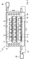
- FIG. 2 shows another embodiment of a freeze-drying system 1 for drying liquid-containing products 10, wherein a receiving device 12 with a plurality of receiving plates 13 arranged one above the other is placed in the vacuum chamber 11. Furthermore, a condenser 22 is housed within the vacuum chamber 11, and the condenser 22 is fluidly connected to a condenser unit 30 to cool the condenser 22. As shown in FIG.
- the products 10 stand on top of the respective receiving plates 13, which in turn have an upper plate wall 26 and a lower plate wall 27 and the fluid space 17 located in between are built up like a sandwich.
- the sound generators 18 are arranged within the fluid space 17 , the fluid space 17 being filled with cooling fluid 16 which is fluidically connected to the unit 25 via the fluid circuit 15 .
- the exemplary embodiment shows that the receiving plates 13 with their sandwich construction can also form the receiving device 12 arranged several times one above the other, so that the receiving plates 13 form floor floors in a certain way, which are each designed in the manner of a sandwich.
- the sound device shown can also control the sound generators 18 individually, in groups or all together in order to inject the ultrasound into the products 10 with frequencies of, for example, 10 kHz to 100 kHz, with the insonification preferably-but not necessarily- being pulsed, for example with pulses off the infrasound range, especially with pulse frequencies from 0.1 Hz to 20 Hz.
Landscapes
- Engineering & Computer Science (AREA)
- Mechanical Engineering (AREA)
- General Engineering & Computer Science (AREA)
- Life Sciences & Earth Sciences (AREA)
- Health & Medical Sciences (AREA)
- Molecular Biology (AREA)
- Chemical & Material Sciences (AREA)
- Combustion & Propulsion (AREA)
- Sustainable Development (AREA)
- Microbiology (AREA)
- Drying Of Solid Materials (AREA)
Priority Applications (1)
| Application Number | Priority Date | Filing Date | Title |
|---|---|---|---|
| HRP20240546TT HRP20240546T1 (hr) | 2021-03-24 | 2021-12-01 | Postrojenje za sušenje zarmzavanjem |
Applications Claiming Priority (1)
| Application Number | Priority Date | Filing Date | Title |
|---|---|---|---|
| DE202021101537.3U DE202021101537U1 (de) | 2021-03-24 | 2021-03-24 | Gefriertrocknungsanlage |
Publications (4)
| Publication Number | Publication Date |
|---|---|
| EP4063774A2 true EP4063774A2 (fr) | 2022-09-28 |
| EP4063774A3 EP4063774A3 (fr) | 2022-10-26 |
| EP4063774C0 EP4063774C0 (fr) | 2024-04-10 |
| EP4063774B1 EP4063774B1 (fr) | 2024-04-10 |
Family
ID=76206711
Family Applications (1)
| Application Number | Title | Priority Date | Filing Date |
|---|---|---|---|
| EP21211699.0A Active EP4063774B1 (fr) | 2021-03-24 | 2021-12-01 | Installation de lyophilisation |
Country Status (7)
| Country | Link |
|---|---|
| US (1) | US12416448B2 (fr) |
| EP (1) | EP4063774B1 (fr) |
| CN (1) | CN115127308A (fr) |
| DE (1) | DE202021101537U1 (fr) |
| ES (1) | ES2980771T3 (fr) |
| HR (1) | HRP20240546T1 (fr) |
| PL (1) | PL4063774T3 (fr) |
Cited By (1)
| Publication number | Priority date | Publication date | Assignee | Title |
|---|---|---|---|---|
| US12416448B2 (en) * | 2021-03-24 | 2025-09-16 | Torsten Pächnatz | Freeze drying plant and method |
Families Citing this family (1)
| Publication number | Priority date | Publication date | Assignee | Title |
|---|---|---|---|---|
| CN114485077B (zh) * | 2022-02-23 | 2024-06-25 | 上海理工大学 | 一种超声辅助冷冻干燥设备 |
Citations (2)
| Publication number | Priority date | Publication date | Assignee | Title |
|---|---|---|---|---|
| CN104677066A (zh) | 2015-03-10 | 2015-06-03 | 中国科学院过程工程研究所 | 一种真空脉动超声干燥设备 |
| WO2019192747A1 (fr) | 2018-04-05 | 2019-10-10 | Paechnatz Torsten | Installation de lyophilisation et procédé associé |
Family Cites Families (18)
| Publication number | Priority date | Publication date | Assignee | Title |
|---|---|---|---|---|
| DE2537850A1 (de) * | 1975-08-26 | 1977-03-10 | Rautenbach Robert | Verfahren zur trocknung von schuettguetern in einem gefriertrockner |
| US5230162A (en) * | 1992-06-26 | 1993-07-27 | Oyler Jr James R | Systems and methods for the deliquification of liquid-containing substances by flash sublimation |
| BE1009377A3 (fr) * | 1995-05-09 | 1997-03-04 | Consejo Superior Investigacion | Procede et dispositif de deshydratation. |
| ATE542095T1 (de) * | 2004-07-23 | 2012-02-15 | Bayer Technology Services Gmbh | Verfahren zum sterilen gefrieren, trocknen, lagern, analysieren und füllen (sfd-saf- verfahren) (verfahren zur gefriertrocknung von granulat für parenterale biopharmazeutika) |
| CN101126593B (zh) * | 2006-08-18 | 2010-11-03 | 发泰(天津)科技有限公司 | 超声冷冻干燥方法及其设备 |
| TWI436789B (zh) * | 2008-01-21 | 2014-05-11 | Intervet Int Bv | 含有藥學化合物的顆粒之冷凍乾燥方法及含有此顆粒的藥學包 |
| CN203385265U (zh) * | 2013-05-29 | 2014-01-08 | 廊坊弘祥隆生物技术有限公司 | 超声低温干燥装置 |
| CN103968649B (zh) * | 2014-05-13 | 2015-12-02 | 上海理工大学 | 一种冷冻干燥方法及配套设备 |
| CN110822822B (zh) * | 2014-06-09 | 2021-08-24 | 泰尔茂比司特公司 | 冻干法 |
| US9671166B2 (en) * | 2014-07-24 | 2017-06-06 | Heat Technologies, Inc. | Acoustic-assisted heat and mass transfer device |
| EP3093597B1 (fr) * | 2015-05-11 | 2017-12-27 | Martin Christ Gefriertrocknungsanlagen GmbH | Installation de lyophilisation |
| DE102015216725A1 (de) | 2015-09-01 | 2017-03-02 | OPTIMA pharma GmbH | Stellplatte für eine Gefriertrocknungsanlage und Gefriertrocknungsanlage |
| DE102016003859A1 (de) | 2016-03-30 | 2017-10-05 | InnoTec GbR (vertretungsber. Gesellschafter Jens Bohne, 99099 Erfurt) | Gefriertrocknung mit Einfluss von Niederfrequenz-Ultraschall |
| DE102018105395B4 (de) * | 2018-03-08 | 2020-01-02 | Griese Patente Gmbh | Infraschall-Ultraschallpumpe zur Gefriertrocknung |
| US11604026B2 (en) * | 2019-03-14 | 2023-03-14 | Terumo Bct Biotechnologies, Llc | Lyophilization loading tray assembly and system |
| US11732964B2 (en) * | 2020-04-15 | 2023-08-22 | Navinta Iii Inc | Lyophilization promoting element |
| DE202021101537U1 (de) * | 2021-03-24 | 2021-05-18 | Torsten Pächnatz | Gefriertrocknungsanlage |
| US12085337B2 (en) * | 2021-10-20 | 2024-09-10 | DSM Sales & Manufacturing, Inc. | Freeze-drying systems and methods |
-
2021
- 2021-03-24 DE DE202021101537.3U patent/DE202021101537U1/de active Active
- 2021-12-01 EP EP21211699.0A patent/EP4063774B1/fr active Active
- 2021-12-01 HR HRP20240546TT patent/HRP20240546T1/hr unknown
- 2021-12-01 ES ES21211699T patent/ES2980771T3/es active Active
- 2021-12-01 PL PL21211699.0T patent/PL4063774T3/pl unknown
-
2022
- 2022-03-24 US US17/703,404 patent/US12416448B2/en active Active
- 2022-03-24 CN CN202210301624.1A patent/CN115127308A/zh active Pending
Patent Citations (2)
| Publication number | Priority date | Publication date | Assignee | Title |
|---|---|---|---|---|
| CN104677066A (zh) | 2015-03-10 | 2015-06-03 | 中国科学院过程工程研究所 | 一种真空脉动超声干燥设备 |
| WO2019192747A1 (fr) | 2018-04-05 | 2019-10-10 | Paechnatz Torsten | Installation de lyophilisation et procédé associé |
Cited By (1)
| Publication number | Priority date | Publication date | Assignee | Title |
|---|---|---|---|---|
| US12416448B2 (en) * | 2021-03-24 | 2025-09-16 | Torsten Pächnatz | Freeze drying plant and method |
Also Published As
| Publication number | Publication date |
|---|---|
| US20220307767A1 (en) | 2022-09-29 |
| ES2980771T3 (es) | 2024-10-03 |
| US12416448B2 (en) | 2025-09-16 |
| PL4063774T3 (pl) | 2024-07-01 |
| EP4063774A3 (fr) | 2022-10-26 |
| HRP20240546T1 (hr) | 2024-07-05 |
| EP4063774C0 (fr) | 2024-04-10 |
| DE202021101537U1 (de) | 2021-05-18 |
| CN115127308A (zh) | 2022-09-30 |
| EP4063774B1 (fr) | 2024-04-10 |
Similar Documents
| Publication | Publication Date | Title |
|---|---|---|
| EP3775739B1 (fr) | Dispositif et procédé de lyophilisation | |
| EP4063774B1 (fr) | Installation de lyophilisation | |
| DE2301807C3 (de) | Verfahren und Vorrichtung zum Kühlen von frischgebackenen mehlhaltigen Nahrungsmitteln | |
| DE3335178C2 (de) | Stromerzeuger in Thermosiphonbauweise | |
| EP2341835A1 (fr) | Dispositif et agencement pour la destruction de cellules tumorales et de tissus tumoraux | |
| DE3836875A1 (de) | Verfahren und vorrichtung zum herstellen von formlingen aus expandierbaren kunststoffpartikeln | |
| DE102012020112A1 (de) | High performance refrigerator having insulated evaporator cover | |
| EP2953654B1 (fr) | Dispositif de stérilisation et procédé de stérilisation avec récupération d'énergie | |
| DE3530242A1 (de) | Verfahren und einrichtung zur erzeugung tiefer temperaturen | |
| AT520285B1 (de) | Verfahren zum Einfrieren einer Flüssigkeit | |
| DE576059C (de) | Gefrierapparat | |
| DE3311525C2 (fr) | ||
| EP2195593B1 (fr) | Dispositif de régulation thermique de produits à lyophiliser | |
| DE102007049278A1 (de) | Vorrichtungen zum Gefriertrocknen | |
| DE4233479C2 (de) | Verfahren und Einrichtung zum Gefriertrocknen, insbesondere von Flüssigkeiten mit Mikroorganismen | |
| DE3137290A1 (de) | "verfahren und vorrichtung zur waermespeicherung bei niedriger temperatur sowie deren anwendung" | |
| DE102011008644A1 (de) | Vorrichtung und Verfahren zum gerichteten Gefrieren | |
| DE3100210C2 (fr) | ||
| EP3504496A1 (fr) | Procédé et dispositif de lyophilisation | |
| DE102024108012A1 (de) | Verfahren zum thermischen Behandeln eines Produkts mittels Dampfs in einem Autoklav mit Kondensatabführung | |
| DE3500688A1 (de) | Anlage zum praeparieren von biologischen objekten | |
| DE1102653B (de) | Vakuumgefrierkammertrockner | |
| DE15840C (de) | Trockenverfahren für Raffinade | |
| DE202012003480U1 (de) | Erdwärmesonde | |
| DE1629143A1 (de) | Eiskondensator |
Legal Events
| Date | Code | Title | Description |
|---|---|---|---|
| PUAI | Public reference made under article 153(3) epc to a published international application that has entered the european phase |
Free format text: ORIGINAL CODE: 0009012 |
|
| STAA | Information on the status of an ep patent application or granted ep patent |
Free format text: STATUS: THE APPLICATION HAS BEEN PUBLISHED |
|
| PUAL | Search report despatched |
Free format text: ORIGINAL CODE: 0009013 |
|
| AK | Designated contracting states |
Kind code of ref document: A2 Designated state(s): AL AT BE BG CH CY CZ DE DK EE ES FI FR GB GR HR HU IE IS IT LI LT LU LV MC MK MT NL NO PL PT RO RS SE SI SK SM TR |
|
| AK | Designated contracting states |
Kind code of ref document: A3 Designated state(s): AL AT BE BG CH CY CZ DE DK EE ES FI FR GB GR HR HU IE IS IT LI LT LU LV MC MK MT NL NO PL PT RO RS SE SI SK SM TR |
|
| RIC1 | Information provided on ipc code assigned before grant |
Ipc: F26B 23/10 20060101ALI20220921BHEP Ipc: F26B 5/02 20060101ALI20220921BHEP Ipc: F26B 5/06 20060101AFI20220921BHEP |
|
| STAA | Information on the status of an ep patent application or granted ep patent |
Free format text: STATUS: REQUEST FOR EXAMINATION WAS MADE |
|
| 17P | Request for examination filed |
Effective date: 20221111 |
|
| RBV | Designated contracting states (corrected) |
Designated state(s): AL AT BE BG CH CY CZ DE DK EE ES FI FR GB GR HR HU IE IS IT LI LT LU LV MC MK MT NL NO PL PT RO RS SE SI SK SM TR |
|
| GRAP | Despatch of communication of intention to grant a patent |
Free format text: ORIGINAL CODE: EPIDOSNIGR1 |
|
| STAA | Information on the status of an ep patent application or granted ep patent |
Free format text: STATUS: GRANT OF PATENT IS INTENDED |
|
| INTG | Intention to grant announced |
Effective date: 20231120 |
|
| GRAS | Grant fee paid |
Free format text: ORIGINAL CODE: EPIDOSNIGR3 |
|
| GRAA | (expected) grant |
Free format text: ORIGINAL CODE: 0009210 |
|
| STAA | Information on the status of an ep patent application or granted ep patent |
Free format text: STATUS: THE PATENT HAS BEEN GRANTED |
|
| AK | Designated contracting states |
Kind code of ref document: B1 Designated state(s): AL AT BE BG CH CY CZ DE DK EE ES FI FR GB GR HR HU IE IS IT LI LT LU LV MC MK MT NL NO PL PT RO RS SE SI SK SM TR |
|
| REG | Reference to a national code |
Ref country code: GB Ref legal event code: FG4D Free format text: NOT ENGLISH |
|
| REG | Reference to a national code |
Ref country code: CH Ref legal event code: EP |
|
| REG | Reference to a national code |
Ref country code: DE Ref legal event code: R096 Ref document number: 502021003286 Country of ref document: DE |
|
| REG | Reference to a national code |
Ref country code: IE Ref legal event code: FG4D Free format text: LANGUAGE OF EP DOCUMENT: GERMAN |
|
| U01 | Request for unitary effect filed |
Effective date: 20240411 |
|
| U07 | Unitary effect registered |
Designated state(s): AT BE BG DE DK EE FI FR IT LT LU LV MT NL PT SE SI Effective date: 20240422 |
|
| REG | Reference to a national code |
Ref country code: HR Ref legal event code: T1PR Ref document number: P20240546 Country of ref document: HR |
|
| REG | Reference to a national code |
Ref country code: SK Ref legal event code: T3 Ref document number: E 44455 Country of ref document: SK |
|
| REG | Reference to a national code |
Ref country code: ES Ref legal event code: FG2A Ref document number: 2980771 Country of ref document: ES Kind code of ref document: T3 Effective date: 20241003 |
|
| PG25 | Lapsed in a contracting state [announced via postgrant information from national office to epo] |
Ref country code: IS Free format text: LAPSE BECAUSE OF FAILURE TO SUBMIT A TRANSLATION OF THE DESCRIPTION OR TO PAY THE FEE WITHIN THE PRESCRIBED TIME-LIMIT Effective date: 20240810 |
|
| PG25 | Lapsed in a contracting state [announced via postgrant information from national office to epo] |
Ref country code: GR Free format text: LAPSE BECAUSE OF FAILURE TO SUBMIT A TRANSLATION OF THE DESCRIPTION OR TO PAY THE FEE WITHIN THE PRESCRIBED TIME-LIMIT Effective date: 20240711 |
|
| PG25 | Lapsed in a contracting state [announced via postgrant information from national office to epo] |
Ref country code: IS Free format text: LAPSE BECAUSE OF FAILURE TO SUBMIT A TRANSLATION OF THE DESCRIPTION OR TO PAY THE FEE WITHIN THE PRESCRIBED TIME-LIMIT Effective date: 20240810 Ref country code: GR Free format text: LAPSE BECAUSE OF FAILURE TO SUBMIT A TRANSLATION OF THE DESCRIPTION OR TO PAY THE FEE WITHIN THE PRESCRIBED TIME-LIMIT Effective date: 20240711 Ref country code: RS Free format text: LAPSE BECAUSE OF FAILURE TO SUBMIT A TRANSLATION OF THE DESCRIPTION OR TO PAY THE FEE WITHIN THE PRESCRIBED TIME-LIMIT Effective date: 20240710 |
|
| REG | Reference to a national code |
Ref country code: HR Ref legal event code: ODRP Ref document number: P20240546 Country of ref document: HR Payment date: 20241121 Year of fee payment: 4 |
|
| REG | Reference to a national code |
Ref country code: DE Ref legal event code: R097 Ref document number: 502021003286 Country of ref document: DE |
|
| PGFP | Annual fee paid to national office [announced via postgrant information from national office to epo] |
Ref country code: NO Payment date: 20241227 Year of fee payment: 4 |
|
| PG25 | Lapsed in a contracting state [announced via postgrant information from national office to epo] |
Ref country code: RO Free format text: LAPSE BECAUSE OF FAILURE TO SUBMIT A TRANSLATION OF THE DESCRIPTION OR TO PAY THE FEE WITHIN THE PRESCRIBED TIME-LIMIT Effective date: 20240410 |
|
| PG25 | Lapsed in a contracting state [announced via postgrant information from national office to epo] |
Ref country code: SM Free format text: LAPSE BECAUSE OF FAILURE TO SUBMIT A TRANSLATION OF THE DESCRIPTION OR TO PAY THE FEE WITHIN THE PRESCRIBED TIME-LIMIT Effective date: 20240410 |
|
| PG25 | Lapsed in a contracting state [announced via postgrant information from national office to epo] |
Ref country code: SM Free format text: LAPSE BECAUSE OF FAILURE TO SUBMIT A TRANSLATION OF THE DESCRIPTION OR TO PAY THE FEE WITHIN THE PRESCRIBED TIME-LIMIT Effective date: 20240410 Ref country code: RO Free format text: LAPSE BECAUSE OF FAILURE TO SUBMIT A TRANSLATION OF THE DESCRIPTION OR TO PAY THE FEE WITHIN THE PRESCRIBED TIME-LIMIT Effective date: 20240410 |
|
| U20 | Renewal fee for the european patent with unitary effect paid |
Year of fee payment: 4 Effective date: 20241227 |
|
| PLBE | No opposition filed within time limit |
Free format text: ORIGINAL CODE: 0009261 |
|
| STAA | Information on the status of an ep patent application or granted ep patent |
Free format text: STATUS: NO OPPOSITION FILED WITHIN TIME LIMIT |
|
| 26N | No opposition filed |
Effective date: 20250113 |
|
| PGFP | Annual fee paid to national office [announced via postgrant information from national office to epo] |
Ref country code: ES Payment date: 20250131 Year of fee payment: 4 |
|
| PGFP | Annual fee paid to national office [announced via postgrant information from national office to epo] |
Ref country code: CH Payment date: 20250101 Year of fee payment: 4 |
|
| PG25 | Lapsed in a contracting state [announced via postgrant information from national office to epo] |
Ref country code: IE Free format text: LAPSE BECAUSE OF NON-PAYMENT OF DUE FEES Effective date: 20241201 |
|
| REG | Reference to a national code |
Ref country code: HR Ref legal event code: ODRP Ref document number: P20240546 Country of ref document: HR Payment date: 20251120 Year of fee payment: 5 |
|
| REG | Reference to a national code |
Ref country code: CH Ref legal event code: U11 Free format text: ST27 STATUS EVENT CODE: U-0-0-U10-U11 (AS PROVIDED BY THE NATIONAL OFFICE) Effective date: 20260101 |
|
| PGFP | Annual fee paid to national office [announced via postgrant information from national office to epo] |
Ref country code: GB Payment date: 20251219 Year of fee payment: 5 |
|
| PGFP | Annual fee paid to national office [announced via postgrant information from national office to epo] |
Ref country code: MC Payment date: 20251223 Year of fee payment: 5 |
|
| PGFP | Annual fee paid to national office [announced via postgrant information from national office to epo] |
Ref country code: HR Payment date: 20251120 Year of fee payment: 5 |
|
| PGFP | Annual fee paid to national office [announced via postgrant information from national office to epo] |
Ref country code: TR Payment date: 20251125 Year of fee payment: 5 |
|
| PGFP | Annual fee paid to national office [announced via postgrant information from national office to epo] |
Ref country code: CZ Payment date: 20251125 Year of fee payment: 5 |
|
| PGFP | Annual fee paid to national office [announced via postgrant information from national office to epo] |
Ref country code: PL Payment date: 20251120 Year of fee payment: 5 |
|
| PGFP | Annual fee paid to national office [announced via postgrant information from national office to epo] |
Ref country code: SK Payment date: 20251125 Year of fee payment: 5 |
|
| U20 | Renewal fee for the european patent with unitary effect paid |
Year of fee payment: 5 Effective date: 20251230 |