EP4063774A2 - Gefriertrocknungsanlage - Google Patents
Gefriertrocknungsanlage Download PDFInfo
- Publication number
- EP4063774A2 EP4063774A2 EP21211699.0A EP21211699A EP4063774A2 EP 4063774 A2 EP4063774 A2 EP 4063774A2 EP 21211699 A EP21211699 A EP 21211699A EP 4063774 A2 EP4063774 A2 EP 4063774A2
- Authority
- EP
- European Patent Office
- Prior art keywords
- products
- drying system
- freeze drying
- vacuum chamber
- fluid
- Prior art date
- Legal status (The legal status is an assumption and is not a legal conclusion. Google has not performed a legal analysis and makes no representation as to the accuracy of the status listed.)
- Granted
Links
Images

Classifications
-
- F—MECHANICAL ENGINEERING; LIGHTING; HEATING; WEAPONS; BLASTING
- F26—DRYING
- F26B—DRYING SOLID MATERIALS OR OBJECTS BY REMOVING LIQUID THEREFROM
- F26B5/00—Drying solid materials or objects by processes not involving the application of heat
- F26B5/04—Drying solid materials or objects by processes not involving the application of heat by evaporation or sublimation of moisture under reduced pressure, e.g. in a vacuum
- F26B5/06—Drying solid materials or objects by processes not involving the application of heat by evaporation or sublimation of moisture under reduced pressure, e.g. in a vacuum the process involving freezing
-
- F—MECHANICAL ENGINEERING; LIGHTING; HEATING; WEAPONS; BLASTING
- F26—DRYING
- F26B—DRYING SOLID MATERIALS OR OBJECTS BY REMOVING LIQUID THEREFROM
- F26B21/00—Arrangements for supplying or controlling air or other gases for drying solid materials or objects
- F26B21/30—Controlling, e.g. regulating, parameters of gas supply
- F26B21/33—Humidity
- F26B21/333—Humidity by condensing the moisture in the drying medium, which may be recycled, e.g. using a heat pump cycle
-
- F—MECHANICAL ENGINEERING; LIGHTING; HEATING; WEAPONS; BLASTING
- F26—DRYING
- F26B—DRYING SOLID MATERIALS OR OBJECTS BY REMOVING LIQUID THEREFROM
- F26B23/00—Heating arrangements
- F26B23/10—Heating arrangements using tubes or passages containing heated fluids, e.g. acting as radiative elements; Closed-loop systems
-
- F—MECHANICAL ENGINEERING; LIGHTING; HEATING; WEAPONS; BLASTING
- F26—DRYING
- F26B—DRYING SOLID MATERIALS OR OBJECTS BY REMOVING LIQUID THEREFROM
- F26B3/00—Drying solid materials or objects by processes involving the application of heat
- F26B3/18—Drying solid materials or objects by processes involving the application of heat by conduction, i.e. the heat is conveyed from the heat source, e.g. gas flame, to the materials or objects to be dried by direct contact
- F26B3/20—Drying solid materials or objects by processes involving the application of heat by conduction, i.e. the heat is conveyed from the heat source, e.g. gas flame, to the materials or objects to be dried by direct contact the heat source being a heated surface, e.g. a moving belt or conveyor
-
- F—MECHANICAL ENGINEERING; LIGHTING; HEATING; WEAPONS; BLASTING
- F26—DRYING
- F26B—DRYING SOLID MATERIALS OR OBJECTS BY REMOVING LIQUID THEREFROM
- F26B5/00—Drying solid materials or objects by processes not involving the application of heat
- F26B5/02—Drying solid materials or objects by processes not involving the application of heat by using ultrasonic vibrations
-
- F—MECHANICAL ENGINEERING; LIGHTING; HEATING; WEAPONS; BLASTING
- F26—DRYING
- F26B—DRYING SOLID MATERIALS OR OBJECTS BY REMOVING LIQUID THEREFROM
- F26B9/00—Machines or apparatus for drying solid materials or objects at rest or with only local agitation; Domestic airing cupboards
- F26B9/06—Machines or apparatus for drying solid materials or objects at rest or with only local agitation; Domestic airing cupboards in stationary drums or chambers
Definitions
- the invention relates to a freeze-drying system for drying liquid-containing products, having a vacuum chamber for receiving the liquid-containing products within the vacuum chamber, a receiving device having a receiving plate being provided, onto which the liquid-containing products can be placed, and a cooling system having a fluid circuit being set up is in order to cool and/or heat the products by means of the cooling fluid guided in the fluid circuit.
- Freeze drying which is known per se, is a process for the gentle evaporation of a wide variety of solvents that are present, for example, in foods, in medicines and the like as a result of production or are naturally present.
- Freeze-drying systems are used to carry out the freeze-drying process, and the drying takes place through the evaporation of the solvent in the product itself.
- the solvent and by this we mean the frozen liquid in the product, must go directly and without prior transition from the solid phase to the liquid phase go from the frozen to the gaseous state, which is called sublimation.
- the product is introduced into the vacuum chamber in the frozen state or is transferred therein to the frozen state.
- the liquid can then be sublimated at significantly lower temperatures, so that the product is not subjected to high thermal loads.
- the low thermal stress enables the properties of the product to be preserved, for example the preservation of oils, aromas and other preferably taste-related properties and the consistency of the product or the preservation of certain temperature-sensitive properties of medicines.
- freeze-drying A well-known example of the use of freeze-drying is the production of so-called instant coffees, which are produced using freeze-drying, in particular in order to preserve the aromatic substances in the soluble coffee for later enjoyment.
- instant coffees which are produced using freeze-drying, in particular in order to preserve the aromatic substances in the soluble coffee for later enjoyment.
- the excellent solubility of the freeze-dried product with the liquid still removed and storage at room temperature are particularly advantageous.
- Freeze-drying systems generally have a vacuum chamber for receiving the products, for which coolable and heatable shelves are formed in the vacuum chamber, and a condenser is provided, which is generally housed in a condenser chamber that can be separated from the receiving space.
- the product is first frozen outside of the vacuum chamber and introduced into the vacuum chamber, which is then closed and evacuated.
- the product is then heated under the created vacuum and the sublimation energy consumed in the course of drying is fed back.
- the condenser is cooled to low temperatures with a refrigeration unit in order to recondense the liquid sublimated from the product from the vapor phase on the surface of the condenser, but without the liquid evaporating again.
- freeze drying is divided into three sub-steps that are separated in time, namely freezing, main drying and secondary drying.
- Lowering the temperature in the product freezes the liquid it contains, although it should be noted that the dissolved substances further lower the freezing point of the liquid.
- the vacuum is created and the pressure is reduced to a value that is below the freezing point of the liquid in the phase diagram.
- the pressure value to be set depends essentially on the liquid temperature to be maintained and is determined using the vapor pressure curve.
- receiving devices generally have receiving plates and a fluid circuit, and a fluid can be guided through corresponding fluid channels in the receiving plate via the fluid circuit.
- Silicone oil for example, is used as the fluid.
- the layer thickness of the dried product also increases from the outside in and the rate of sublimation increases.
- the shelf temperature on the top of the receiving plates is continuously increased, although the maximum temperature is limited in order not to damage the product, in particular to prevent the liquid contained in the product from thawing.
- pressures of, for example, 1 mbar to 10 mbar are usual.
- the remaining liquid that is still bound in the product matrix is drawn off.
- the temperature of the surfaces on the mounting plates is increased even further, while the lowest achievable pressure in the vacuum chamber of, for example, 3 mbar to 10 mbar is achieved.
- Known freeze-drying systems are constructed in such a way that the vacuum chamber is separated from the condenser chamber, for example via a partition and an intermediate valve incorporated in the partition. Once sublimation has started and the vapor pressure in the vacuum chamber increases, the valve is opened and the solvent vapor, for example water vapor, can pass into the condenser chamber and onto the surface of the condenser knock down.
- the condensers consist of cooling coils, for example, and are cooled to low temperatures with a refrigerant via a compressor. After completion of the drying process, the vacuum chamber and usually also the condenser chamber are vented to normal pressure again.
- a freeze-drying system for drying liquid-containing products having a vacuum chamber which is designed to receive the liquid-containing products, wherein a receiving device is provided with at least one receiving plate onto which the liquid-containing products can be placed, and wherein a cooling system is set up with a fluid circuit , in order to cool and/or heat the products by means of the cooling fluid guided in the fluid circuit.
- sound generators are arranged on the receiving plates below the product shelves.
- a fluid space is formed below the receiving plate, the sound generators then being arranged on the side facing away from the vacuum chamber on the outside of the fluid space and having to sound through the cooling fluid in order to sound ultrasound into the product.
- a freeze-drying system for drying liquid-containing products, having a vacuum chamber for receiving the liquid-containing products within the vacuum chamber, wherein a receiving device is provided with a receiving plate onto which the liquid-containing products can be placed, and wherein a cooling system with a fluid circuit is set up to of the cooling fluid guided in the fluid circuit to cool and/or heat the products.
- a sound generator for injecting sound into the cooling fluid itself in order to introduce the ultrasound to the product by means of the cooling fluid.
- the object of the invention is to improve a freeze-drying system for drying liquid-containing products.
- the use of ultrasound as a supporting means in the drying of liquid-containing products is to be improved, preferably in order to accelerate the drying process and, as a result, to achieve a simpler construction of the freeze-drying system.
- the invention provides that the receiving plate has at least one closed fluid chamber which is connected to the fluid circuit and through which the cooling fluid can flow, and at least one sound generator for insonifying ultrasound into the products during a Drying phase is provided, wherein the sound generator is set up in the fluid space and cooling fluid can flow around it.
- the core of the invention is the arrangement of the at least one or more sound generators within a fluid space that is formed in the receiving plate and on which the products that are intended for drying can be placed. If the sound generators are integrated directly in the mounting plate, the product can be applied to the top side of a surface of an upper plate wall and the sound generators can be arranged directly on the underside of the same plate wall.
- the receiving plate can be designed in such a way that it has several positioning surfaces on a top support surface, or the receiving plate has a circumferentially raised edge area that makes it possible to apply products to be dried as bulk material to the receiving plate.
- the fluid space enables a planar cooling or planar heating of the upper plate wall, so that an optimal heat transfer can be achieved either into the product or out of the product through the cooling fluid.
- the heat transfer only has to take place through the upper plate wall, so that both the heat transfer over the surface is evened out and thus optimized, and that the insonification of ultrasound is intensified.
- This optimization is achieved by using the upper plate wall on the one hand as a delimitation of the fluid space and on the other hand as a wall to accommodate the sound generators.
- the fluid wets the entire surface of the inside of the upper plate wall to the extent that the remaining surface between, for example, several sound generators is wetted or washed with cooling fluid.
- the receiving plate is designed with a flat extension and has a double-walled structure with an upper plate wall and a preferably parallel spaced lower plate wall, the upper plate wall with the respective arrangements and functions already being described above.
- the flat fluid space extends between the upper panel wall and the lower panel wall, with the at least one support surface for placing the products being formed on the upper side of the upper panel wall and the at least one sound generator being arranged on the underside of the upper panel wall.
- the sonic head is regarded as the sound generator, so that the sonic head or also the sonotrode is fastened to the underside of the upper plate wall.
- a unit that stimulates the ultrasound by means of an electric current can also be arranged outside of the fluid space, for example on the underside of the lower plate wall.
- the freeze-drying system is designed in such a way that a coolable condenser is present, on which liquid that can be extracted from the products of a drying phase of the process can be precipitated from a vapor phase.
- the condenser on which the liquid removed from the products can be condensed from a vapor phase, can be designed as a cooling coil, with a condenser unit being provided as a peripheral unit outside the freeze-drying system, which is fluidically connected to the coolable condenser.
- a condenser chamber can be provided for accommodating the condenser, which chamber is connected to the vacuum chamber by means of an intermediate valve. If the vapor pressure of the sublimated liquid rises to a certain value within the vacuum chamber, the intermediate valve can be opened at the appropriate time, so that the liquid can be condensed from the vapor phase at the condenser. The liquid vapor flows from the vacuum chamber through the intermediate valve into the condenser chamber.
- an advantageous arrangement has also developed according to which the coolable condenser is set up together with the products that can be fed into the vacuum chamber.
- the coolable condenser is set up together with the products that can be fed into the vacuum chamber.
- there is no condenser chamber which is connected to the vacuum chamber via an intermediate valve.
- Repeated tests have shown advantageous drying cycles in a very short drying time, in which the products could be dried, with the liquid being able to condense on the coolable condenser inside the vacuum chamber.
- the advantageous arrangement of setting up the coolable condenser inside the vacuum chamber is particularly in connection with the insonification of ultrasound into the products to be dried.
- the receiving plate forms a base plate of the vacuum chamber, which delimits the vacuum chamber on the underside.
- the mounting plate can be integrated into the structure of the vacuum chamber that both the fluid connections for the flow through the fluid space with cooling fluid and the electrical Connection of the sound generators can be set up outside the vacuum chamber.
- the upper plate wall is designed as part of a housing body enclosing the vacuum chamber.
- This housing body also includes the base plate, it being particularly conceivable that a side wall or a wall on the top side is formed by means of the upper plate wall of the receiving plate, depending on the form in which the product to be dried is present, for example as bulk material.
- the bulk material is delimited both from the bottom and from the top with an upper plate wall of a receiving plate, so that both a heat exchange and an insonification of ultrasound into the product from at least two sides or from several sides into the product is done.
- the upper plate wall is designed as a base plate of the vacuum chamber, there is preferably only one receiving plate in the freeze-drying system, in particular in a structural unit with the housing of the vacuum chamber.
- a receiving plate can also form the bottom plate of the vacuum chamber, and further receiving plates are located inside the vacuum chamber, for example by the receiving device being designed like a shelf and having several levels, which are formed by the receiving plates and into which the products to be dried can be placed.
- the receiving device for receiving a large number of products can have several receiving plates arranged one above the other in tiers, which are designed with the respective fluid chambers and in which the respective sound generators are integrated.
- the multiple recording plates are about one Pipe system connected to the outer fluid circuit of the cooling system, wherein the pipe system is set up as part of the fluid circuit within the vacuum chamber.
- the condenser that can be cooled is located in the vacuum chamber, it can be designed in such a way that the condenser that can be cooled encloses or surrounds the receiving device and thus the products to be dried, for example in a ring shape.
- the sound generators can be arranged in a multiple arrangement next to each other on the underside of the upper plate wall within the fluid space, with the sound generators preferably having a plate shape with a sound surface with which the sound generators are arranged on the upper plate wall, so that an ultrasound can be sounded flatly into the upper plate wall is.
- the sound generator can be designed to insonate an ultrasound into the products with an ultrasound frequency of 10kHz to 100kHz.
- a sonic device can be provided for this purpose, to which one or more sonic generators can be connected, the sonic device being operatively connected to the at least one sonic generator for injecting ultrasound into the products with an ultrasonic frequency of 10 kHz to 100 kHz.
- the sonic device is designed to emit pulsed ultrasound into the products in operative connection with the sonic generator.
- the sonic device can be designed in operative connection with the sonic generator to inject the ultrasound into the products with pulses in the infrasound range of 0.1 Hz to 20 Hz.
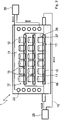
- FIG 1 shows a freeze-drying system 1, which is used for drying liquid-containing products 10, wherein the products 10 are shown as piece goods, and the liquid-containing products 10 can also be designed as bulk goods.
- the products 10 are held on a holding device 12 which, for example, comprises a single holding plate 13 .
- the receiving plate 13 has a sandwich structure and has an upper plate wall 26 and a lower plate wall 27 .
- a fluid space 17 filled with cooling fluid 16 is set up between the upper plate wall 26 and the lower plate wall 27 .
- the cooling fluid 16 is connected to a fluid circuit 15, which is either heated or cooled via a unit 25, depending on the cooling or heating phase of the products 10 in the freeze-drying process of the freeze-drying system 1.
- the upper panel wall 26 is designed as a base panel 23 of the housing body 29 of the vacuum chamber 11 .
- the base plate 23 and the upper plate wall 26 of the receiving plate 13 form a single component, with a plurality of sound generators 18 being arranged on the underside of the upper plate wall 26 .
- the sound generators 18 are located on a respective position of the flat receiving plate 13, which corresponds to the positioning position of the products 10. If the sound generators 18 are operated, ultrasound can be radiated directly into the products 10 through the upper plate wall 26 or through the bottom plate 23 .
- the wetting of the underside of the upper plate wall 26 from the direction of the fluid chamber 17 also promotes heat transfer either into the product 10 when the cooling fluid 16 is heated or out of the product 10 when the cooling fluid 16 is cooled.
- the sonic device 31 arranged outside of the vacuum chamber 11 generates an ultrasound with the sonic generators 18 , the number of sonic generators 18 shown being operated together with the one sonic device 31 .
- FIG. 2 shows another embodiment of a freeze-drying system 1 for drying liquid-containing products 10, wherein a receiving device 12 with a plurality of receiving plates 13 arranged one above the other is placed in the vacuum chamber 11. Furthermore, a condenser 22 is housed within the vacuum chamber 11, and the condenser 22 is fluidly connected to a condenser unit 30 to cool the condenser 22. As shown in FIG.
- the products 10 stand on top of the respective receiving plates 13, which in turn have an upper plate wall 26 and a lower plate wall 27 and the fluid space 17 located in between are built up like a sandwich.
- the sound generators 18 are arranged within the fluid space 17 , the fluid space 17 being filled with cooling fluid 16 which is fluidically connected to the unit 25 via the fluid circuit 15 .
- the exemplary embodiment shows that the receiving plates 13 with their sandwich construction can also form the receiving device 12 arranged several times one above the other, so that the receiving plates 13 form floor floors in a certain way, which are each designed in the manner of a sandwich.
- the sound device shown can also control the sound generators 18 individually, in groups or all together in order to inject the ultrasound into the products 10 with frequencies of, for example, 10 kHz to 100 kHz, with the insonification preferably-but not necessarily- being pulsed, for example with pulses off the infrasound range, especially with pulse frequencies from 0.1 Hz to 20 Hz.
Landscapes
- Engineering & Computer Science (AREA)
- Mechanical Engineering (AREA)
- General Engineering & Computer Science (AREA)
- Life Sciences & Earth Sciences (AREA)
- Health & Medical Sciences (AREA)
- Molecular Biology (AREA)
- Chemical & Material Sciences (AREA)
- Combustion & Propulsion (AREA)
- Sustainable Development (AREA)
- Microbiology (AREA)
- Drying Of Solid Materials (AREA)
Abstract
Description
- Die Erfindung bezieht sich auf eine Gefriertrocknungsanlage zum Trocknen von flüssigkeitshaltigen Produkten, aufweisend eine Vakuumkammer zur Aufnahme der flüssigkeitshaltigen Produkte innerhalb der Vakuumkammer, wobei eine Aufnahmevorrichtung mit einer Aufnahmeplatte vorgesehen ist, auf die die flüssigkeitshaltigen Produkte aufgebbar sind, und wobei ein Kühlsystem mit einem Fluidkreislauf eingerichtet ist, um mittels des im Fluidkreislauf geführten Kühlfluids die Produkte zu kühlen und/oder zu heizen.
- Die an sich bekannte Gefriertrocknung ist ein Verfahren zur schonenden Evaporation von verschiedensten Lösungsmitteln, die beispielsweise in Lebensmitteln, in Arzneien und dergleichen herstellungsbedingt oder auf natürliche Weise vorhanden sind.
- Zur Ausführung des Verfahrens der Gefriertrocknung dienen Gefriertrocknungsanlagen, und die Trocknung erfolgt durch die Evaporation des Lösungsmittels im Produkt selbst. Das Lösungsmittel, und damit ist die gefrorene Flüssigkeit im Produkt gemeint, muss dabei direkt und ohne vorherigen Übergang von der festen Phase in die flüssige Phase vom gefrorenen in den gasförmigen Zustand über gehen, was als Sublimation bezeichnet wird. Insofern wird das Produkt im gefrorenen Zustand in die Vakuumkammer eingegeben oder in dieser in den gefrorenen Zustand überführt. Durch die Erzeugung eines Vakuums kann die Flüssigkeit anschließend bei deutlich niedrigeren Temperaturen bereits sublimiert werden, sodass das Produkt thermisch nicht hoch belastet wird. Die niedrige thermische Belastung ermöglicht dabei den Erhalt der Eigenschaften des Produktes, beispielsweise den Erhalt von Ölen, Aromen und weiteren vorzugsweise geschmacklichen Eigenschaften sowie der Konsistenz des Produktes oder den Erhalt bestimmter temperatursensibler Eigenschaften von Arzneien.
- Ein bekanntes Beispiel für den Einsatz der Gefriertrocknung ist die Herstellung sogenannter Instant-Kaffees, die hergestellt werden unter Verwendung der Gefriertrocknung, insbesondere um die Aromastoffe im löslichen Kaffee auch für den späteren Genuss zu erhalten. Neben der Erhaltung der ursprünglichen Eigenschaften der Produkte sind vor allem die ausgezeichnete Löslichkeit des gefriergetrockneten Produktes bei dennoch entfernter Flüssigkeit und die Lagerung bei Raumtemperatur von Vorteil.
- Gefriertrocknungsanlagen weisen in der Regel eine Vakuumkammer zur Aufnahme der Produkte auf, wofür in der Vakuumkammer kühlbare und heizbare Stellflächen ausgebildet sind, und es ist ein Kondensator vorgesehen, der in der Regel in einer vom Aufnahmeraum trennbaren Kondensatorkammer untergebracht ist.
- Das Produkt wird beispielsweise zunächst außerhalb der Vakuumkammer eingefroren und in die Vakuumkammer eingebracht, die anschließend verschlossen und evakuiert wird. Das Produkt wird daraufhin unter dem erzeugten Vakuum erwärmt und im Verlauf der Trocknung verbrauchte Sublimationsenergie wird wieder zugeführt. Der Kondensator wird dabei mit einem Kälteaggregat auf tiefe Temperaturen gekühlt, um die aus dem Produkt sublimierte Flüssigkeit aus der Dampfphase auf der Oberfläche des Kondensators wieder zu kondensieren, jedoch ohne dass die Flüssigkeit wieder verdampft.
- In den Gefriertrocknungsprozess gehen vielseitige Parameter wie die Abkühlgeschwindigkeit, die Einfriertemperatur, das Vakuum in der Vakuumkammer, die Stellflächentemperatur zur Aufnahme der Produkte und beispielsweise die Länge der Haupttrocknung ein, wodurch die Komplexität des Verfahrens bereits deutlich wird. Aufgrund der komplexen Verfahrensführung ist zur Optimierung des Gefriertrocknungsprozesses eine präzise Mess- und Regeltechnik für die Erfassung der Temperatur und des Druckes sowie weiterer Parameter notwendig.
- Grundsätzlich wird die Gefriertrocknung in drei zeitlich voneinander abzugrenzende Teilschritte unterteilt, nämlich dem Einfrieren, der Haupttrocknung und der Nachtrocknung. Durch das Senken der Temperatur im Produkt wird die enthaltene Flüssigkeit gefroren, wobei zu beachten ist, dass der Gefrierpunkt der Flüssigkeit durch die gelösten Stoffe weiter abgesenkt wird. Danach wird das Vakuum erzeugt und der Druck auf einen Wert abgesenkt, der im Phasendiagramm unterhalb des Gefrierpunktes der Flüssigkeit liegt. Der einzustellende Druckwert richtet sich im Wesentlichen nach der einzuhaltenden Flüssigkeitstemperatur und wird mit Hilfe der Dampfdruckkurve ermittelt.
- Der eigentliche Trocknungsvorgang findet ausschließlich durch Sublimation von Flüssigkeit im Produkt unter dem eingestellten Druckvakuum statt. Die zur Entfernung der Flüssigkeit aus dem Produkt verbrauchte Sublimationsenergie in der Haupttrocknung wird dem Produkt in der Aufnahmevorrichtung in Form von Wärme wieder zugeführt. Hierzu weisen Aufnahmevorrichtungen in der Regel Aufnahmeplatten und eine Fluidkreislauf auf, und über den Fluidkreislauf kann ein Fluid durch entsprechende Fluidkanäle in der Aufnahmeplatte hindurchgeführt werden.
- Als Fluid wird beispielsweise Silikonöl verwendet. Mit fortschreitender Trocknung des Produktes wächst dabei auch die Schichtdicke des getrockneten Produktes von außen nach innen und die Sublimationsrate sind. Um die Sublimation aufrecht zu erhalten, wird die Stellflächentemperatur auf der Oberseite der Aufnahmeplatten kontinuierlich erhöht, wobei jedoch die maximale Temperatur begrenzt ist, um das Produkt nicht zu schädigen, insbesondere dass es nicht zu einem Antauen der im Produkt enthaltenen Flüssigkeit kommt. In der Haupttrocknung sind dabei Drücke von beispielsweise 1 mbar bis 10 mbar üblich. Bei der Nachtrocknung wird die verbleibende Flüssigkeit abgezogen, die noch in der Produktmatrix gebunden ist. In der Praxis wird dabei die Temperatur der Stellflächen auf den Aufnahmeplatten noch weiter erhöht, während der niedrigste erreichbare Druck in der Vakuumkammer von beispielsweise 3 mbar bis 10 mbar realisiert wird.
- Bekannte Gefriertrocknungsanlagen sind so aufgebaut, dass die Vakuumkammer beispielsweise über eine Zwischenwand und einem in der Zwischenwand eingebrachten Zwischenventil von der Kondensatorkammer getrennt ist. Hat die Sublimation eingesetzt und steigt der Dampfdruck in der Vakuumkammer, so wird das Ventil geöffnet und der Lösungsmitteldampf, beispielsweise Wasserdampf, kann in die Kondensatorkammer übertreten und an der Oberfläche des Kondensators niederschlagen. Die Kondensatoren bestehen beispielsweise aus Kühlschlangen und werden mit einem Kältemittel über einen Kompressor auf niedrige Temperaturen gekühlt. Nach Beendigung des Trocknungsprozesses wird die Vakuumkammer und in der Regel auch die Kondensatorkammer wieder auf Normaldruck belüftet.
- Aus der
CN 104677066 A ist eine Gefriertrocknungsanlage zum Trocknen von flüssigkeitshaltigen Produkten bekannt, aufweisend eine Vakuumkammer, die zur Aufnahme der flüssigkeitshaltigen Produkte ausgebildet ist, wobei eine Aufnahmevorrichtung mit wenigstens einer Aufnahmeplatte vorgesehen ist, auf die die flüssigkeitshaltigen Produkte aufgebbar sind, und wobei ein Kühlsystem mit einem Fluidkreislauf eingerichtet ist, um mittels des im Fluidkreislauf geführten Kühlfluids die Produkte zu kühlen und/oder zu heizen. Zur Einschallung eines Ultraschalles in die zu trocknenden Produkte sind Schallgeneratoren unterhalb der Stellflächen der Produkte an den Aufnahmeplatten angeordnet. Gemäß einer Ausführungsform ist ein Fluidraum unterhalb der Aufnahmeplatte ausgebildet, wobei dann die Schallgeneratoren von der der Vakuumkammer abgewandten Seite an der Außenseite des Fluidraumes angeordnet sind und durch das Kühlfluid hindurchschallen müssen, um einen Ultraschall in das Produkt einzuschallen. - Regelmäßig ist es üblich, das Produkt vor dem Einbringen in die Vakuumkammer mit Ultraschall zu beschallen, insbesondere in der Einfrierphase, um eine Eiskristallbildung im Gefriervorgang der Flüssigkeit im Produkt zu begünstigen, wodurch die nachfolgende Sublimation in der Vakuumkammer verbessert und vor allem schneller ausgeführt werden kann. Um den Trocknungsvorgang des Produktes in der Vakuumkammer und unter Vakuumatmosphäre zu begünstigen, wird der Ultraschall in der Regel begleitend hierzu nicht mehr verwendet.
- Aus der
WO/2019/192747 ist eine Gefriertrocknungsanlage zum Trocknen von flüssigkeitshaltigen Produkten, aufweisend eine Vakuumkammer zur Aufnahme der flüssigkeitshaltigen Produkte innerhalb der Vakuumkammer, wobei eine Aufnahmevorrichtung mit einer Aufnahmeplatte vorgesehen ist, auf die die flüssigkeitshaltigen Produkte aufgebbar sind, und wobei ein Kühlsystem mit einem Fluidkreislauf eingerichtet ist, um mittels des im Fluidkreislauf geführten Kühlfluids die Produkte zu kühlen und/oder zu heizen. Dabei wird vorgeschlagen, wenigstens einen Schallgenerator dazu einzurichten, in das Kühlfluid selbst einzuschallen, um den Ultraschall mittels des Kühlfluides an das Produkt heranzuführen. - Die Aufgabe der Erfindung ist eine Verbesserung einer Gefriertrocknungsanlage zum Trocknen von flüssigkeitshaltigen Produkten. Insbesondere soll der Einsatz von Ultraschall als unterstützendes Mittel bei der Trocknung der flüssigkeitshaltigen Produkte verbessert werden, vorzugsweise um den Trocknungsprozess zu beschleunigen und um im Ergebnis einen einfacheren Aufbau der Gefriertrocknungsanlage zu erreichen.
- Diese Aufgabe wird ausgehend von einer Gefriertrocknungsanlage zum Trocknen von flüssigkeitshaltigen Produkten gemäß dem Oberbegriff des Anspruches 1 mit den jeweils kennzeichnenden Merkmalen gelöst. Vorteilhafte Weiterbildungen der Erfindung sind in den abhängigen Ansprüchen angegeben.
- Die Erfindung sieht zur Verbesserung der Gefriertrocknungsanlage vor, dass die Aufnahmeplatte wenigstens einen geschlossenen Fluidraum aufweist, der an den Fluidkreislauf angeschlossen ist und der mit dem Kühlfluid durchströmbar ist, und wobei wenigstens ein Schallgenerator zur Einschallung von Ultraschall in die Produkte während einer Trocknungsphase vorgesehen ist, wobei der Schallgenerator im Fluidraum eingerichtet und mit Kühlfluid umströmbar ist.
- Kern der Erfindung ist die Anordnung des wenigstens einen oder mehrerer Schallgeneratoren innerhalb eines Fluidraums, der in der Aufnahmeplatte ausgebildet ist und auf der die Produkte aufgebracht werden können, die zur Trocknung vorgesehen sind. Werden die Schallgeneratoren direkt in der Aufnahmeplatte integriert, so kann über eine Fläche einer oberen Plattenwand auf der Oberseite das Produkt aufgebracht werden und unmittelbar auf der Unterseite derselben Plattenwand können die Schallgeneratoren angeordnet sein.
- Dadurch wird eine wesentlich intensivere Einschallung von Ultraschall in die zu trocknenden Produkte erreicht. Die Aufnahmeplatte kann so ausgeführt sein, dass diese mehrere Stellflächen auf einer oberseitigen Auflagefläche aufweist oder die Aufnahmeplatte weist einen umlaufend erhöhten Randbereich auf, der es ermöglicht, zu trocknende Produkte als Schüttgut auf die Aufnahmeplatte aufzubringen. Der Fluidraum ermöglicht dabei eine flächige Kühlung oder flächige Erwärmung der oberen Plattenwand, sodass ein optimaler Wärmeübergang entweder in das Produkt hinein oder aus dem Produkt heraus durch das Kühlfluid erreicht werden kann. Der Wärmeübergang muss lediglich durch die obere Plattenwand erfolgen, sodass sowohl der Wärmeübergang über der Fläche vergleichmäßigt und damit optimiert ist, als auch dass die Einschallung von Ultraschall intensiviert ist.
- Erreicht wird diese Optimierung durch die Nutzung der oberen Plattenwand einerseits als Begrenzung des Fluidraums und andererseits als Aufnahmewand zur Aufnahme der Schallgeneratoren. Das Fluid benetzt dabei die Innenseite der oberen Plattenwand insoweit vollflächig, als dass die verbleibende Fläche zwischen beispielsweise mehreren Schallgeneratoren mit Kühlfluid benetzt bzw. umspült ist.
- Insbesondere ist die Aufnahmeplatte mit einer flächigen Erstreckung ausgeführt und weist einen doppelwandigen Aufbau mit einer oberen Plattenwand und mit einer vorzugsweise parallel beabstandeten unteren Plattenwand auf, wobei die obere Plattenwand mit den jeweiligen Anordnungen und Funktionen vorstehend bereits beschrieben ist. Zwischen der oberen Plattenwand und der unteren Plattenwand erstreckt sich der flächige Fluidraum, wobei auf der Oberseite der oberen Plattenwand die wenigstens eine Auflagefläche zur Auflage der Produkte ausgebildet ist und auf der Unterseite der oberen Plattenwand ist der wenigstens eine Schallgenerator angeordnet.
- Als Schallgenerator wird vorliegend der Schallkopf angesehen, sodass der Schallkopf oder auch die Sonotrode an der Unterseite der oberen Plattenwand befestigt ist. Eine Einheit, die mittels eines elektrischen Stromes den Ultraschall anregt, kann insofern auch außerhalb des Fluidraums angeordnet sein, beispielsweise unterseitig der unteren Plattenwand.
- Mit weiterem Vorteil ist die Gefriertrocknungsanlage so ausgebildet, dass ein kühlbarer Kondensator vorhanden ist, an dem aus den Produkten einer Trocknungsphase des Prozesses entziehbare Flüssigkeit aus einer Dampfphase niederschlagbar ist. Der Kondensator, an dem die aus den Produkten entzogene Flüssigkeit aus einer Dampfphase niedergeschlagen werden kann, kann als Kühlschlange ausgebildet sein, wobei außerhalb der Gefriertrocknungsanlage als periphere Einheit eine Kondensatoreinheit vorgesehen sein kann, die fluidisch mit dem kühlbaren Kondensator verbunden ist.
- Es kann zur Aufnahme des Kondensators eine Kondensatorkammer vorgesehen werden, die mittels eines Zwischenventils mit der Vakuumkammer verbunden ist. Steigt der Dampfdruck der sublimierten Flüssigkeit innerhalb der Vakuumkammer auf einen bestimmten Wert an, kann das Zwischenventil zu gegebener Zeit geöffnet werden, sodass die Flüssigkeit aus der Dampfphase am Kondensator niedergeschlagen werden kann. Dabei strömt der Flüssigkeitsdampf von der Vakuumkammer durch das Zwischenventil in die Kondensatorkammer über.
- Alternativ hat sich auch eine vorteilhafte Anordnung herausgebildet, gemäß der der kühlbare Kondensator gemeinsam mit den eingebbaren Produkten in der Vakuumkammer eingerichtet ist. Gemäß dieser Variante entfällt eine Kondensatorkammer, die über ein Zwischenventil mit der Vakuumkammer verbunden ist. Versuche haben in mehrfacher Wiederholung vorteilhafte Trocknungszyklen in sehr kurzer Trocknungszeit gezeigt, in denen die Produkte getrocknet werden konnten, wobei sich die Flüssigkeit an dem kühlbaren Kondensator bereits innerhalb der Vakuumkammer hat niederschlagen können. Insbesondere in Verbindung mit dem Einschallen von Ultraschall in die zu trocknenden Produkte ergibt sich die vorteilhafte Anordnung, den kühlbaren Kondensator innerhalb der Vakuumkammer einzurichten.
- Gemäß einer weiteren besonders bevorzugten Ausgestaltung der Gefriertrocknungsanlage bildet die Aufnahmeplatte eine Bodenplatte der Vakuumkammer, die die Vakuumkammer unterseitig begrenzt. Damit wird der Vorteil erreicht, dass der Schallgenerator, der in Verbindung mit der Aufnahmeplatte angeordnet ist, nicht innerhalb der Vakuumkammer eingerichtet werden muss, wodurch auch die elektrischen Verbindungen vereinfacht werden. Die Aufnahmeplatte kann so in die Struktur der Vakuumkammer integriert werden, dass sowohl die Fluidanschlüsse zur Durchströmung des Fluidraums mit Kühlfluid als auch die elektrische Verbindung der Schallgeneratoren außerhalb der Vakuumkammer eingerichtet werden können. Insbesondere ist es von Vorteil, wenn die obere Plattenwand als Teil eines die Vakuumkammer umschließenden Gehäusekörpers ausgebildet ist. Dieser Gehäusekörper umfasst dabei auch die Bodenplatte, wobei es insbesondere denkbar ist, dass eine Seitenwand oder eine deckenseitige Wand mittels der oberen Plattenwand der Aufnahmeplatte gebildet ist, abhängig davon, in welcher Form das zu trocknende Produkt vorliegt, beispielsweise als Schüttgut.
- So ist es durchaus denkbar, dass das Schüttgut sowohl von der Unterseite als auch von der Oberseite mit einer oberen Plattenwand einer Aufnahmeplatte begrenzt ist, sodass sowohl ein Wärmeaustausch als auch eine Einschallung von Ultraschall in das Produkt von wenigstens zwei Seiten oder von mehreren Seiten in das Produkt erfolgt. Ist die obere Plattenwand als Bodenplatte der Vakuumkammer ausgebildet, so befindet sich vorzugsweise nur eine Aufnahmeplatte in der Gefriertrocknungsanlage, insbesondere in baulicher Einheit mit dem Gehäuse der Vakuumkammer.
- Selbstverständlich besteht aber auch die Möglichkeit, mehrere Aufnahmeplatten übereinander innerhalb der Vakuumkammer anzuordnen. Dabei kann auch eine Aufnahmeplatte die Bodenplatte der Vakuumkammer bilden, und weitere Aufnahmeplatten befinden sich innerhalb der Vakuumkammer, beispielsweise indem die Aufnahmevorrichtung regalartig ausgeführt ist und mehrere Etagen aufweist, die durch die Aufnahmeplatten gebildet sind und in denen die zu trocknenden Produkte eingebracht werden können. Insofern kann die Aufnahmevorrichtung zur Aufnahme einer Vielzahl von Produkten mehrere etagenweise übereinander angeordnete Aufnahmeplatten aufweisen, die mit dem jeweiligen Fluidräumen ausgebildet sind und in die jeweils die Schallgeneratoren integriert sind. Die mehreren Aufnahmeplatten sind dabei über ein Rohrsystem mit dem äußeren Fluidkreislauf des Kühlsystems verbunden, wobei das Rohrsystem damit als Teil des Fluidkreislaufs innerhalb der Vakuumkammer eingerichtet ist.
- Befindet sich der kühlbare Kondensator in der Vakuumkammer, so kann dieser so ausgeführt sein, dass der kühlbare Kondensator die Aufnahmevorrichtung und damit die zu trocknenden Produkte umschließt oder umgibt, beispielsweise ringförmig.
- Die Schallgeneratoren können in mehrfacher Anordnung nebeneinander an der Unterseite der oberen Plattenwand innerhalb des Fluidraums angeordnet sein, wobei die Schallgeneratoren vorzugsweise eine Tellerform mit einer Schallfläche aufweisen, mit der die Schallgeneratoren an der oberen Plattenwand angeordnet sind, sodass ein Ultraschall in die obere Plattenwand flächig einschallbar ist.
- Der Schallgenerator kann zur Einschallung eines Ultraschalls in die Produkte mit einer Ultraschallfrequenz von 10kHz bis 100kHz ausgebildet werden. Hierfür kann ein Schallgerät vorgesehen werden, an dem insbesondere ein oder mehrere Schallgeneratoren angeschlossen werden können, wobei das Schallgerät in Wirkverbindung mit dem wenigstens einen Schallgenerator zur Einschallung eines Ultraschalls in die Produkte mit einer Ultraschallfrequenz von 10kHz bis 100kHz ausgebildet ist.
- Besonders vorteilhaft ist es, wenn das Schallgerät dazu ausgebildet ist, in Wirkverbindung mit dem Schallgenerator den Ultraschall gepulst in die Produkte einzuschallen. Beispielsweise kann das Schallgerät in Wirkverbindung mit dem Schallgenerator dazu ausgebildet werden, den Ultraschall mit Pulsen im Bereich des Infraschalles von 0,1Hz bis 20Hz in die Produkte einzuschallen.
- Weitere, die Erfindung verbessernde Maßnahmen werden nachstehend gemeinsam mit der Beschreibung bevorzugter Ausführungsbeispiele der Erfindung anhand der Figuren näher dargestellt. Es zeigt:
- Figur 1
- eine schematische Ansicht eines Ausführungsbeispiels einer Gefriertrocknungsanlage mit einer erfindungsgemäßen Aufnahmeplatte als Bodenplatte der Vakuumkammer und
- Figur 2
- eine schematische Ansicht eines Ausführungsbeispiels einer Gefriertrocknungsanlage mit mehreren erfindungsgemäßen Aufnahmeplatten, die etagenweise übereinander angeordnet sind.
-
Figur 1 zeigt eine Gefriertrocknungsanlage 1, die zum Trocknen von flüssigkeitshaltigen Produkten 10 dient, wobei die Produkte 10 als Stückgut dargestellt sind, und die flüssigkeitshaltigen Produkte 10 können auch als Schüttgut ausgeführt sein. - Die Produkte 10 sind auf einer Aufnahmevorrichtung 12 aufgenommen, die beispielhaft eine einzige Aufnahmeplatte 13 umfasst. Die Aufnahmeplatte 13 ist sandwichartig aufgebaut und weist eine obere Plattenwand 26 und eine untere Plattenwand 27 auf. Zwischen der oberen Plattenwand 26 und der unteren Plattenwand 27 ist ein Fluidraum 17 eingerichtet, der mit Kühlfluid 16 gefüllt ist.
- Das Kühlfluid 16 ist an ein Fluidkreislauf 15 angeschlossen, das über ein Aggregat 25 entweder geheizt oder gekühlt wird, je nach Phase der Kühlung oder Erwärmung der Produkte 10 in dem Gefriertrocknungsprozess der Gefriertrocknungsanlage 1.
- Die obere Plattenwand 26 ist gemäß diesem Ausführungsbeispiel als Bodenplatte 23 des Gehäusekörpers 29 der Vakuumkammer 11 ausgestaltet. Insofern bildet die Bodenplatte 23 und die obere Plattenwand 26 der Aufnahmeplatte 13 ein einheitliches Bauteil, wobei auf der Unterseite der oberen Plattenwand 26 mehrere Schallgeneratoren 18 angeordnet sind. Die Schallgeneratoren 18 befinden sich auf einer jeweiligen Position der flächigen Aufnahmeplatte 13, die mit der Stellposition der Produkte 10 übereinstimmt. Werden die Schallgeneratoren 18 betrieben, so kann Ultraschall unmittelbar durch die obere Plattenwand 26 bzw. durch die Bodenplatte 23 in die Produkte 10 eingeschallt werden. Durch die Benetzung der Unterseite der oberen Plattenwand 26 aus Richtung des Fluidraumes 17 erfolgt ferner ein begünstigter Wärmeübergang entweder in das Produkt 10 hinein, wenn das Kühlfluid 16 erhitzt wird, oder aus dem Produkt 10 heraus, wenn das Kühlfluid 16 gekühlt wird. Das außerhalb der Vakuumkammer 11 angeordnete Schallgerät 31 erzeugt mit den Schallgeneratoren 18 einen Ultraschall, wobei die Anzahl der gezeigten Schallgeneratoren 18 mit dem einen Schallgerät 31 gemeinsam betrieben wird.
-
Figur 2 zeigt ein weiteres Ausführungsbeispiel einer Gefriertrocknungsanlage 1 zum Trocknen von flüssigkeitshaltigen Produkten 10, wobei eine Aufnahmevorrichtung 12 mit mehreren übereinander angeordneten Aufnahmeplatten 13 in der Vakuumkammer 11 eingebracht ist. Weiterhin ist ein Kondensator 22 innerhalb der Vakuumkammer 11 eingebracht, und der Kondensator 22 ist mit einer Kondensatoreinheit 30 fluidisch verbunden, um den Kondensator 22 zu kühlen. - Die Produkte 10 stehen auf der Oberseite der jeweiligen Aufnahmeplatten 13 auf, die wiederum mit einer oberen Plattenwand 26 und einer unteren Plattenwand 27 und dem sich dazwischen befindenden Fluidraum 17 sandwichartig aufgebaut sind. Innerhalb des Fluidraums 17 sind die Schallgeneratoren 18 angeordnet, wobei der Fluidraum 17 mit Kühlfluid 16 gefüllt ist, dass über den Fluidkreislauf 15 mit dem Aggregat 25 fluidisch verbunden ist.
- Das Ausführungsbeispiel zeigt, dass die Aufnahmeplatten 13 mit ihrem Sandwichaufbau auch mehrfach übereinander angeordnet die Aufnahmevorrichtung 12 bilden können, sodass die Aufnahmeplatten 13 in gewisser Weise Etagenböden bilden, die jeweils sandwichartig ausgebildet sind. Das in
Figur 1 gezeigte Schallgerät kann auch gemäß diesem Ausführungsbeispiel die Schallgeneratoren 18 einzeln, gruppenweise oder alle gemeinsam ansteuern, um den Ultraschall mit Frequenzen von beispielsweise 10kHz bis 100kHz in de Produkte 10 einzuschallen, wobei die Einschallung vorzugsweise -aber nicht zwingend- gepulst erfolgt, beispielsweise mit Pulsen aus dem Infraschallbereich, insbesondere mit Pulsfrequenzen von 0,1 Hz bis 20Hz. - Die Erfindung beschränkt sich in ihrer Ausführung nicht auf das vorstehend angegebene bevorzugte Ausführungsbeispiel. Vielmehr ist eine Anzahl von Varianten denkbar, welche von der dargestellten Lösung auch bei einer grundsätzlich anders gearteten Ausführung Gebrauch macht. Sämtliche aus den Ansprüchen, der Beschreibung oder den Zeichnungen hervorgehenden Merkmale und/oder Vorteile, einschließlich konstruktiver Einzelheiten oder räumlicher Anordnungen, können sowohl für sich als auch in den verschiedensten Kombinationen erfindungswesentlich sein.
-
- 1
- Gefriertrocknungsanlage
- 10
- Produkt
- 11
- Vakuumkammer
- 12
- Aufnahmevorrichtung
- 13
- Aufnahmeplatte
- 14
- Kühlsystem
- 15
- Fluidkreislauf
- 16
- Kühlfluid
- 17
- Fluidraum
- 18
- Schallgenerator
- 19
- Kondensator
- 20
- Kondensatorkammer
- 21
- Zwischenventil
- 22
- Kondensator
- 23
- Bodenplatte
- 24
- Schallfläche
- 25
- Aggregat
- 26
- obere Plattenwand
- 27
- untere Plattenwand
- 28
- Auflagefläche
- 29
- Gehäusekörper
- 30
- Kondensatoreinheit
- 31
- Schallgerät
Claims (15)
- Gefriertrocknungsanlage (1) zum Trocknen von flüssigkeitshaltigen Produkten (10),- aufweisend eine Vakuumkammer (11), die zur Aufnahme der flüssigkeitshaltigen Produkte (10) ausgebildet ist,- wobei eine Aufnahmevorrichtung (12) mit wenigstens einer Aufnahmeplatte (13) vorgesehen ist, auf die die flüssigkeitshaltigen Produkte (10) aufgebbar sind,- und wobei ein Kühlsystem (14) mit einem Fluidkreislauf (15) eingerichtet ist, um mittels des im Fluidkreislauf (15) geführten Kühlfluids (16) die Produkte (10) zu kühlen und/oder zu heizen, dadurch gekennzeichnet,
dass- die Aufnahmeplatte (13) wenigstens einen geschlossenen Fluidraum (17) aufweist, der an den Fluidkreislauf (15) angeschlossen ist und der mit dem Kühlfluid (16) durchströmbar ist, wobei- wenigstens ein Schallgenerator (18) zur Einschallung von Ultraschall in die Produkte (10) während einer Trocknungsphase vorgesehen ist, wobei der Schallgenerator (18) im Fluidraum (17) eingerichtet und mit Kühlfluid (16) umströmbar ist. - Gefriertrocknungsanlage (1) nach Anspruch 1,
dadurch gekennzeichnet,
dass die Aufnahmeplatte (13) eine flächige Erstreckung aufweist und doppelwandig mit einer oberen Plattenwand (26) und einer unteren Plattenwand (27) ausgebildet ist, zwischen denen der Fluidraum (17) ausgebildet ist und wobei auf der Oberseite der oberen Plattenwand (26) wenigstens eine Auflagefläche (28) zur Auflage der Produkte (10) ausgebildet ist und auf der Unterseite der oberen Plattenwand (26) der wenigstens eine Schallgenerator (18) angeordnet ist. - Gefriertrocknungsanlage (1) nach Anspruch 1 oder 2,
dadurch gekennzeichnet,
dass ein kühlbarer Kondensator (19, 22) vorhanden ist, an dem aus den Produkten (10) in einer Trocknungsphase entziehbare Flüssigkeit aus einer Dampfphase niederschlagbar ist. - Gefriertrocknungsanlage (1) nach Anspruch 3,
dadurch gekennzeichnet,
dass eine Kondensatorkammer (20) vorgesehen ist, wobei der kühlbare Kondensator (19) in der Kondensatorkammer (20) aufgenommen ist, und wobei die Kondensatorkammer (20) mittels eines Zwischenventils (21) mit der Vakuumkammer (11) verbunden ist. - Gefriertrocknungsanlage (1) nach Anspruch 3,
dadurch gekennzeichnet,
dass der kühlbare Kondensator (22) gemeinsam mit den eingebbaren Produkten (10) in der Vakuumkammer (11) eingerichtet ist. - Gefriertrocknungsanlage (1) nach einem der vorgenannten Ansprüche,
dadurch gekennzeichnet,
dass die Aufnahmeplatte (13) eine Bodenplatte (23) der Vakuumkammer (11) bildet, die die Vakuumkammer (11) unterseitig begrenzt. - Gefriertrocknungsanlage (1) nach einem der vorgenannten Ansprüche,
dadurch gekennzeichnet,
dass die obere Plattenwand (26) als Teil eines die Vakuumkammer (11) umschließenden Gehäusekörpers (29) ausgebildet ist. - Gefriertrocknungsanlage (1) nach einem der vorgenannten Ansprüche,
dadurch gekennzeichnet,
dass die Aufnahmevorrichtung (12) zur Aufnahme einer Vielzahl von Produkten (10) mehrere etagenweise übereinander angeordnete Aufnahmeplatten (13) mit den mit diesen ausgebildeten Fluidräumen (17) aufweist. - Gefriertrocknungsanlage (1) nach einem der vorgenannten Ansprüche,
dadurch gekennzeichnet,
dass der kühlbare Kondensator (22) so in der Vakuumkammer (11) eingerichtet ist, dass dieser die Aufnahmevorrichtung (12) mit den darin anordenbaren Produkten (10) umgibt. - Gefriertrocknungsanlage (1) nach einem der vorgenannten Ansprüche,
dadurch gekennzeichnet,
dass der Schallgenerator (18) zur Einschallung eines Ultraschalls in die Produkte (10) mit einer Ultraschallfrequenz von 10kHz bis 100kHz ausgebildet ist. - Gefriertrocknungsanlage (1) nach einem der vorgenannten Ansprüche,
dadurch gekennzeichnet,
dass der Schallgenerator (18) zur Einschallung eines Ultraschalls in die Produkte (10) mit einer Ultraschallfrequenz von 10kHz bis 100kHz ausgebildet ist. - Gefriertrocknungsanlage (1) nach einem der vorgenannten Ansprüche,
dadurch gekennzeichnet,
dass wenigstens ein Schallgerät (31) vorgesehen ist, das in Wirkverbindung mit dem Schallgenerator (18) zur Einschallung eines Ultraschalls in die Produkte (10) mit einer Ultraschallfrequenz von 10kHz bis 100kHz ausgebildet ist. - Gefriertrocknungsanlage (1) nach Anspruch 12,
dadurch gekennzeichnet,
dass das Schallgerät (31) dazu ausgebildet ist, in Wirkverbindung mit dem Schallgenerator (18) den Ultraschall gepulst in die Produkte (10) einzuschallen. - Gefriertrocknungsanlage (1) nach Anspruch 13,
dadurch gekennzeichnet,
dass das Schallgerät (31) in Wirkverbindung mit dem Schallgenerator (18) dazu ausgebildet ist, den Ultraschall mit Pulsen im Bereich des Infraschalles von 0,1Hz bis 20Hz in die Produkte (10) einzuschallen. - Gefriertrocknungsanlage (1) nach einem der vorgenannten Ansprüche,
dadurch gekennzeichnet,
dass mehrere Schallgeneratoren (18) nebeneinander an der Unterseite der oberen Plattenwand (26) und innerhalb des Fluidraumes (17) angeordnet sind, wobei die Schallgeneratoren (18) eine Tellerform mit einer Schallfläche (24) aufweisen, mit der die Schallgeneratoren (18) an der oberen Plattenwand (26) angeordnet sind, sodass ein Ultraschall in die obere Plattenwand (26) flächig einschallbar ist.
Priority Applications (1)
| Application Number | Priority Date | Filing Date | Title |
|---|---|---|---|
| HRP20240546TT HRP20240546T1 (hr) | 2021-03-24 | 2021-12-01 | Postrojenje za sušenje zarmzavanjem |
Applications Claiming Priority (1)
| Application Number | Priority Date | Filing Date | Title |
|---|---|---|---|
| DE202021101537.3U DE202021101537U1 (de) | 2021-03-24 | 2021-03-24 | Gefriertrocknungsanlage |
Publications (4)
| Publication Number | Publication Date |
|---|---|
| EP4063774A2 true EP4063774A2 (de) | 2022-09-28 |
| EP4063774A3 EP4063774A3 (de) | 2022-10-26 |
| EP4063774C0 EP4063774C0 (de) | 2024-04-10 |
| EP4063774B1 EP4063774B1 (de) | 2024-04-10 |
Family
ID=76206711
Family Applications (1)
| Application Number | Title | Priority Date | Filing Date |
|---|---|---|---|
| EP21211699.0A Active EP4063774B1 (de) | 2021-03-24 | 2021-12-01 | Gefriertrocknungsanlage |
Country Status (7)
| Country | Link |
|---|---|
| US (1) | US12416448B2 (de) |
| EP (1) | EP4063774B1 (de) |
| CN (1) | CN115127308A (de) |
| DE (1) | DE202021101537U1 (de) |
| ES (1) | ES2980771T3 (de) |
| HR (1) | HRP20240546T1 (de) |
| PL (1) | PL4063774T3 (de) |
Cited By (1)
| Publication number | Priority date | Publication date | Assignee | Title |
|---|---|---|---|---|
| US12416448B2 (en) * | 2021-03-24 | 2025-09-16 | Torsten Pächnatz | Freeze drying plant and method |
Families Citing this family (1)
| Publication number | Priority date | Publication date | Assignee | Title |
|---|---|---|---|---|
| CN114485077B (zh) * | 2022-02-23 | 2024-06-25 | 上海理工大学 | 一种超声辅助冷冻干燥设备 |
Citations (2)
| Publication number | Priority date | Publication date | Assignee | Title |
|---|---|---|---|---|
| CN104677066A (zh) | 2015-03-10 | 2015-06-03 | 中国科学院过程工程研究所 | 一种真空脉动超声干燥设备 |
| WO2019192747A1 (de) | 2018-04-05 | 2019-10-10 | Paechnatz Torsten | Gefriertrocknungsanlage und verfahren hierzu |
Family Cites Families (18)
| Publication number | Priority date | Publication date | Assignee | Title |
|---|---|---|---|---|
| DE2537850A1 (de) * | 1975-08-26 | 1977-03-10 | Rautenbach Robert | Verfahren zur trocknung von schuettguetern in einem gefriertrockner |
| US5230162A (en) * | 1992-06-26 | 1993-07-27 | Oyler Jr James R | Systems and methods for the deliquification of liquid-containing substances by flash sublimation |
| BE1009377A3 (fr) * | 1995-05-09 | 1997-03-04 | Consejo Superior Investigacion | Procede et dispositif de deshydratation. |
| ATE542095T1 (de) * | 2004-07-23 | 2012-02-15 | Bayer Technology Services Gmbh | Verfahren zum sterilen gefrieren, trocknen, lagern, analysieren und füllen (sfd-saf- verfahren) (verfahren zur gefriertrocknung von granulat für parenterale biopharmazeutika) |
| CN101126593B (zh) * | 2006-08-18 | 2010-11-03 | 发泰(天津)科技有限公司 | 超声冷冻干燥方法及其设备 |
| TWI436789B (zh) * | 2008-01-21 | 2014-05-11 | Intervet Int Bv | 含有藥學化合物的顆粒之冷凍乾燥方法及含有此顆粒的藥學包 |
| CN203385265U (zh) * | 2013-05-29 | 2014-01-08 | 廊坊弘祥隆生物技术有限公司 | 超声低温干燥装置 |
| CN103968649B (zh) * | 2014-05-13 | 2015-12-02 | 上海理工大学 | 一种冷冻干燥方法及配套设备 |
| CN110822822B (zh) * | 2014-06-09 | 2021-08-24 | 泰尔茂比司特公司 | 冻干法 |
| US9671166B2 (en) * | 2014-07-24 | 2017-06-06 | Heat Technologies, Inc. | Acoustic-assisted heat and mass transfer device |
| EP3093597B1 (de) * | 2015-05-11 | 2017-12-27 | Martin Christ Gefriertrocknungsanlagen GmbH | Gefriertrocknungsanlage |
| DE102015216725A1 (de) | 2015-09-01 | 2017-03-02 | OPTIMA pharma GmbH | Stellplatte für eine Gefriertrocknungsanlage und Gefriertrocknungsanlage |
| DE102016003859A1 (de) | 2016-03-30 | 2017-10-05 | InnoTec GbR (vertretungsber. Gesellschafter Jens Bohne, 99099 Erfurt) | Gefriertrocknung mit Einfluss von Niederfrequenz-Ultraschall |
| DE102018105395B4 (de) * | 2018-03-08 | 2020-01-02 | Griese Patente Gmbh | Infraschall-Ultraschallpumpe zur Gefriertrocknung |
| US11604026B2 (en) * | 2019-03-14 | 2023-03-14 | Terumo Bct Biotechnologies, Llc | Lyophilization loading tray assembly and system |
| US11732964B2 (en) * | 2020-04-15 | 2023-08-22 | Navinta Iii Inc | Lyophilization promoting element |
| DE202021101537U1 (de) * | 2021-03-24 | 2021-05-18 | Torsten Pächnatz | Gefriertrocknungsanlage |
| US12085337B2 (en) * | 2021-10-20 | 2024-09-10 | DSM Sales & Manufacturing, Inc. | Freeze-drying systems and methods |
-
2021
- 2021-03-24 DE DE202021101537.3U patent/DE202021101537U1/de active Active
- 2021-12-01 EP EP21211699.0A patent/EP4063774B1/de active Active
- 2021-12-01 HR HRP20240546TT patent/HRP20240546T1/hr unknown
- 2021-12-01 ES ES21211699T patent/ES2980771T3/es active Active
- 2021-12-01 PL PL21211699.0T patent/PL4063774T3/pl unknown
-
2022
- 2022-03-24 US US17/703,404 patent/US12416448B2/en active Active
- 2022-03-24 CN CN202210301624.1A patent/CN115127308A/zh active Pending
Patent Citations (2)
| Publication number | Priority date | Publication date | Assignee | Title |
|---|---|---|---|---|
| CN104677066A (zh) | 2015-03-10 | 2015-06-03 | 中国科学院过程工程研究所 | 一种真空脉动超声干燥设备 |
| WO2019192747A1 (de) | 2018-04-05 | 2019-10-10 | Paechnatz Torsten | Gefriertrocknungsanlage und verfahren hierzu |
Cited By (1)
| Publication number | Priority date | Publication date | Assignee | Title |
|---|---|---|---|---|
| US12416448B2 (en) * | 2021-03-24 | 2025-09-16 | Torsten Pächnatz | Freeze drying plant and method |
Also Published As
| Publication number | Publication date |
|---|---|
| US20220307767A1 (en) | 2022-09-29 |
| ES2980771T3 (es) | 2024-10-03 |
| US12416448B2 (en) | 2025-09-16 |
| PL4063774T3 (pl) | 2024-07-01 |
| EP4063774A3 (de) | 2022-10-26 |
| HRP20240546T1 (hr) | 2024-07-05 |
| EP4063774C0 (de) | 2024-04-10 |
| DE202021101537U1 (de) | 2021-05-18 |
| CN115127308A (zh) | 2022-09-30 |
| EP4063774B1 (de) | 2024-04-10 |
Similar Documents
| Publication | Publication Date | Title |
|---|---|---|
| EP3775739B1 (de) | Gefriertrocknungsanlage und verfahren hierzu | |
| EP4063774B1 (de) | Gefriertrocknungsanlage | |
| DE2301807C3 (de) | Verfahren und Vorrichtung zum Kühlen von frischgebackenen mehlhaltigen Nahrungsmitteln | |
| DE3335178C2 (de) | Stromerzeuger in Thermosiphonbauweise | |
| EP2341835A1 (de) | Vorrichtung und anordnung zur zerstörung von tumorzellen und tumorgewebe | |
| DE3836875A1 (de) | Verfahren und vorrichtung zum herstellen von formlingen aus expandierbaren kunststoffpartikeln | |
| DE102012020112A1 (de) | High performance refrigerator having insulated evaporator cover | |
| EP2953654B1 (de) | Sterilisationsvorrichtung und sterilisationsverfahren mit energierückgewinnung | |
| DE3530242A1 (de) | Verfahren und einrichtung zur erzeugung tiefer temperaturen | |
| AT520285B1 (de) | Verfahren zum Einfrieren einer Flüssigkeit | |
| DE576059C (de) | Gefrierapparat | |
| DE3311525C2 (de) | ||
| EP2195593B1 (de) | Vorrichtung zum temperieren von gefriergut | |
| DE102007049278A1 (de) | Vorrichtungen zum Gefriertrocknen | |
| DE4233479C2 (de) | Verfahren und Einrichtung zum Gefriertrocknen, insbesondere von Flüssigkeiten mit Mikroorganismen | |
| DE3137290A1 (de) | "verfahren und vorrichtung zur waermespeicherung bei niedriger temperatur sowie deren anwendung" | |
| DE102011008644A1 (de) | Vorrichtung und Verfahren zum gerichteten Gefrieren | |
| DE3100210C2 (de) | ||
| EP3504496A1 (de) | Verfahren und vorrichtung zur gefriertrocknung | |
| DE102024108012A1 (de) | Verfahren zum thermischen Behandeln eines Produkts mittels Dampfs in einem Autoklav mit Kondensatabführung | |
| DE3500688A1 (de) | Anlage zum praeparieren von biologischen objekten | |
| DE1102653B (de) | Vakuumgefrierkammertrockner | |
| DE15840C (de) | Trockenverfahren für Raffinade | |
| DE202012003480U1 (de) | Erdwärmesonde | |
| DE1629143A1 (de) | Eiskondensator |
Legal Events
| Date | Code | Title | Description |
|---|---|---|---|
| PUAI | Public reference made under article 153(3) epc to a published international application that has entered the european phase |
Free format text: ORIGINAL CODE: 0009012 |
|
| STAA | Information on the status of an ep patent application or granted ep patent |
Free format text: STATUS: THE APPLICATION HAS BEEN PUBLISHED |
|
| PUAL | Search report despatched |
Free format text: ORIGINAL CODE: 0009013 |
|
| AK | Designated contracting states |
Kind code of ref document: A2 Designated state(s): AL AT BE BG CH CY CZ DE DK EE ES FI FR GB GR HR HU IE IS IT LI LT LU LV MC MK MT NL NO PL PT RO RS SE SI SK SM TR |
|
| AK | Designated contracting states |
Kind code of ref document: A3 Designated state(s): AL AT BE BG CH CY CZ DE DK EE ES FI FR GB GR HR HU IE IS IT LI LT LU LV MC MK MT NL NO PL PT RO RS SE SI SK SM TR |
|
| RIC1 | Information provided on ipc code assigned before grant |
Ipc: F26B 23/10 20060101ALI20220921BHEP Ipc: F26B 5/02 20060101ALI20220921BHEP Ipc: F26B 5/06 20060101AFI20220921BHEP |
|
| STAA | Information on the status of an ep patent application or granted ep patent |
Free format text: STATUS: REQUEST FOR EXAMINATION WAS MADE |
|
| 17P | Request for examination filed |
Effective date: 20221111 |
|
| RBV | Designated contracting states (corrected) |
Designated state(s): AL AT BE BG CH CY CZ DE DK EE ES FI FR GB GR HR HU IE IS IT LI LT LU LV MC MK MT NL NO PL PT RO RS SE SI SK SM TR |
|
| GRAP | Despatch of communication of intention to grant a patent |
Free format text: ORIGINAL CODE: EPIDOSNIGR1 |
|
| STAA | Information on the status of an ep patent application or granted ep patent |
Free format text: STATUS: GRANT OF PATENT IS INTENDED |
|
| INTG | Intention to grant announced |
Effective date: 20231120 |
|
| GRAS | Grant fee paid |
Free format text: ORIGINAL CODE: EPIDOSNIGR3 |
|
| GRAA | (expected) grant |
Free format text: ORIGINAL CODE: 0009210 |
|
| STAA | Information on the status of an ep patent application or granted ep patent |
Free format text: STATUS: THE PATENT HAS BEEN GRANTED |
|
| AK | Designated contracting states |
Kind code of ref document: B1 Designated state(s): AL AT BE BG CH CY CZ DE DK EE ES FI FR GB GR HR HU IE IS IT LI LT LU LV MC MK MT NL NO PL PT RO RS SE SI SK SM TR |
|
| REG | Reference to a national code |
Ref country code: GB Ref legal event code: FG4D Free format text: NOT ENGLISH |
|
| REG | Reference to a national code |
Ref country code: CH Ref legal event code: EP |
|
| REG | Reference to a national code |
Ref country code: DE Ref legal event code: R096 Ref document number: 502021003286 Country of ref document: DE |
|
| REG | Reference to a national code |
Ref country code: IE Ref legal event code: FG4D Free format text: LANGUAGE OF EP DOCUMENT: GERMAN |
|
| U01 | Request for unitary effect filed |
Effective date: 20240411 |
|
| U07 | Unitary effect registered |
Designated state(s): AT BE BG DE DK EE FI FR IT LT LU LV MT NL PT SE SI Effective date: 20240422 |
|
| REG | Reference to a national code |
Ref country code: HR Ref legal event code: T1PR Ref document number: P20240546 Country of ref document: HR |
|
| REG | Reference to a national code |
Ref country code: SK Ref legal event code: T3 Ref document number: E 44455 Country of ref document: SK |
|
| REG | Reference to a national code |
Ref country code: ES Ref legal event code: FG2A Ref document number: 2980771 Country of ref document: ES Kind code of ref document: T3 Effective date: 20241003 |
|
| PG25 | Lapsed in a contracting state [announced via postgrant information from national office to epo] |
Ref country code: IS Free format text: LAPSE BECAUSE OF FAILURE TO SUBMIT A TRANSLATION OF THE DESCRIPTION OR TO PAY THE FEE WITHIN THE PRESCRIBED TIME-LIMIT Effective date: 20240810 |
|
| PG25 | Lapsed in a contracting state [announced via postgrant information from national office to epo] |
Ref country code: GR Free format text: LAPSE BECAUSE OF FAILURE TO SUBMIT A TRANSLATION OF THE DESCRIPTION OR TO PAY THE FEE WITHIN THE PRESCRIBED TIME-LIMIT Effective date: 20240711 |
|
| PG25 | Lapsed in a contracting state [announced via postgrant information from national office to epo] |
Ref country code: IS Free format text: LAPSE BECAUSE OF FAILURE TO SUBMIT A TRANSLATION OF THE DESCRIPTION OR TO PAY THE FEE WITHIN THE PRESCRIBED TIME-LIMIT Effective date: 20240810 Ref country code: GR Free format text: LAPSE BECAUSE OF FAILURE TO SUBMIT A TRANSLATION OF THE DESCRIPTION OR TO PAY THE FEE WITHIN THE PRESCRIBED TIME-LIMIT Effective date: 20240711 Ref country code: RS Free format text: LAPSE BECAUSE OF FAILURE TO SUBMIT A TRANSLATION OF THE DESCRIPTION OR TO PAY THE FEE WITHIN THE PRESCRIBED TIME-LIMIT Effective date: 20240710 |
|
| REG | Reference to a national code |
Ref country code: HR Ref legal event code: ODRP Ref document number: P20240546 Country of ref document: HR Payment date: 20241121 Year of fee payment: 4 |
|
| REG | Reference to a national code |
Ref country code: DE Ref legal event code: R097 Ref document number: 502021003286 Country of ref document: DE |
|
| PGFP | Annual fee paid to national office [announced via postgrant information from national office to epo] |
Ref country code: NO Payment date: 20241227 Year of fee payment: 4 |
|
| PG25 | Lapsed in a contracting state [announced via postgrant information from national office to epo] |
Ref country code: RO Free format text: LAPSE BECAUSE OF FAILURE TO SUBMIT A TRANSLATION OF THE DESCRIPTION OR TO PAY THE FEE WITHIN THE PRESCRIBED TIME-LIMIT Effective date: 20240410 |
|
| PG25 | Lapsed in a contracting state [announced via postgrant information from national office to epo] |
Ref country code: SM Free format text: LAPSE BECAUSE OF FAILURE TO SUBMIT A TRANSLATION OF THE DESCRIPTION OR TO PAY THE FEE WITHIN THE PRESCRIBED TIME-LIMIT Effective date: 20240410 |
|
| PG25 | Lapsed in a contracting state [announced via postgrant information from national office to epo] |
Ref country code: SM Free format text: LAPSE BECAUSE OF FAILURE TO SUBMIT A TRANSLATION OF THE DESCRIPTION OR TO PAY THE FEE WITHIN THE PRESCRIBED TIME-LIMIT Effective date: 20240410 Ref country code: RO Free format text: LAPSE BECAUSE OF FAILURE TO SUBMIT A TRANSLATION OF THE DESCRIPTION OR TO PAY THE FEE WITHIN THE PRESCRIBED TIME-LIMIT Effective date: 20240410 |
|
| U20 | Renewal fee for the european patent with unitary effect paid |
Year of fee payment: 4 Effective date: 20241227 |
|
| PLBE | No opposition filed within time limit |
Free format text: ORIGINAL CODE: 0009261 |
|
| STAA | Information on the status of an ep patent application or granted ep patent |
Free format text: STATUS: NO OPPOSITION FILED WITHIN TIME LIMIT |
|
| 26N | No opposition filed |
Effective date: 20250113 |
|
| PGFP | Annual fee paid to national office [announced via postgrant information from national office to epo] |
Ref country code: ES Payment date: 20250131 Year of fee payment: 4 |
|
| PGFP | Annual fee paid to national office [announced via postgrant information from national office to epo] |
Ref country code: CH Payment date: 20250101 Year of fee payment: 4 |
|
| PG25 | Lapsed in a contracting state [announced via postgrant information from national office to epo] |
Ref country code: IE Free format text: LAPSE BECAUSE OF NON-PAYMENT OF DUE FEES Effective date: 20241201 |
|
| REG | Reference to a national code |
Ref country code: HR Ref legal event code: ODRP Ref document number: P20240546 Country of ref document: HR Payment date: 20251120 Year of fee payment: 5 |
|
| REG | Reference to a national code |
Ref country code: CH Ref legal event code: U11 Free format text: ST27 STATUS EVENT CODE: U-0-0-U10-U11 (AS PROVIDED BY THE NATIONAL OFFICE) Effective date: 20260101 |
|
| PGFP | Annual fee paid to national office [announced via postgrant information from national office to epo] |
Ref country code: GB Payment date: 20251219 Year of fee payment: 5 |
|
| PGFP | Annual fee paid to national office [announced via postgrant information from national office to epo] |
Ref country code: MC Payment date: 20251223 Year of fee payment: 5 |
|
| PGFP | Annual fee paid to national office [announced via postgrant information from national office to epo] |
Ref country code: HR Payment date: 20251120 Year of fee payment: 5 |
|
| PGFP | Annual fee paid to national office [announced via postgrant information from national office to epo] |
Ref country code: TR Payment date: 20251125 Year of fee payment: 5 |
|
| PGFP | Annual fee paid to national office [announced via postgrant information from national office to epo] |
Ref country code: CZ Payment date: 20251125 Year of fee payment: 5 |
|
| PGFP | Annual fee paid to national office [announced via postgrant information from national office to epo] |
Ref country code: PL Payment date: 20251120 Year of fee payment: 5 |
|
| PGFP | Annual fee paid to national office [announced via postgrant information from national office to epo] |
Ref country code: SK Payment date: 20251125 Year of fee payment: 5 |
|
| U20 | Renewal fee for the european patent with unitary effect paid |
Year of fee payment: 5 Effective date: 20251230 |