EP4063973B1 - Uhr mit integriertem stellglied, das eine elektromechanische vorrichtung umfasst - Google Patents
Uhr mit integriertem stellglied, das eine elektromechanische vorrichtung umfasst Download PDFInfo
- Publication number
- EP4063973B1 EP4063973B1 EP21205508.1A EP21205508A EP4063973B1 EP 4063973 B1 EP4063973 B1 EP 4063973B1 EP 21205508 A EP21205508 A EP 21205508A EP 4063973 B1 EP4063973 B1 EP 4063973B1
- Authority
- EP
- European Patent Office
- Prior art keywords
- permanent magnet
- rest position
- mechanical element
- mechanical
- force
- Prior art date
- Legal status (The legal status is an assumption and is not a legal conclusion. Google has not performed a legal analysis and makes no representation as to the accuracy of the status listed.)
- Active
Links
Images




Classifications
-
- G—PHYSICS
- G04—HOROLOGY
- G04C—ELECTROMECHANICAL CLOCKS OR WATCHES
- G04C3/00—Electromechanical clocks or watches independent of other time-pieces and in which the movement is maintained by electric means
- G04C3/04—Electromechanical clocks or watches independent of other time-pieces and in which the movement is maintained by electric means wherein movement is regulated by a balance
-
- G—PHYSICS
- G04—HOROLOGY
- G04C—ELECTROMECHANICAL CLOCKS OR WATCHES
- G04C3/00—Electromechanical clocks or watches independent of other time-pieces and in which the movement is maintained by electric means
- G04C3/04—Electromechanical clocks or watches independent of other time-pieces and in which the movement is maintained by electric means wherein movement is regulated by a balance
- G04C3/042—Electromechanical clocks or watches independent of other time-pieces and in which the movement is maintained by electric means wherein movement is regulated by a balance using mechanical coupling
- G04C3/045—Electromechanical clocks or watches independent of other time-pieces and in which the movement is maintained by electric means wherein movement is regulated by a balance using mechanical coupling with constant impulses
-
- G—PHYSICS
- G04—HOROLOGY
- G04C—ELECTROMECHANICAL CLOCKS OR WATCHES
- G04C11/00—Synchronisation of independently-driven clocks
- G04C11/08—Synchronisation of independently-driven clocks using an electro-magnet or-motor for oscillation correction
- G04C11/081—Synchronisation of independently-driven clocks using an electro-magnet or-motor for oscillation correction using an electro-magnet
- G04C11/084—Synchronisation of independently-driven clocks using an electro-magnet or-motor for oscillation correction using an electro-magnet acting on the balance
-
- G—PHYSICS
- G04—HOROLOGY
- G04C—ELECTROMECHANICAL CLOCKS OR WATCHES
- G04C3/00—Electromechanical clocks or watches independent of other time-pieces and in which the movement is maintained by electric means
- G04C3/04—Electromechanical clocks or watches independent of other time-pieces and in which the movement is maintained by electric means wherein movement is regulated by a balance
- G04C3/047—Electromechanical clocks or watches independent of other time-pieces and in which the movement is maintained by electric means wherein movement is regulated by a balance using other coupling means, e.g. electrostrictive, magnetostrictive
-
- G—PHYSICS
- G04—HOROLOGY
- G04C—ELECTROMECHANICAL CLOCKS OR WATCHES
- G04C3/00—Electromechanical clocks or watches independent of other time-pieces and in which the movement is maintained by electric means
- G04C3/04—Electromechanical clocks or watches independent of other time-pieces and in which the movement is maintained by electric means wherein movement is regulated by a balance
- G04C3/06—Electromechanical clocks or watches independent of other time-pieces and in which the movement is maintained by electric means wherein movement is regulated by a balance using electromagnetic coupling between electric power source and balance
- G04C3/065—Electromechanical clocks or watches independent of other time-pieces and in which the movement is maintained by electric means wherein movement is regulated by a balance using electromagnetic coupling between electric power source and balance the balance controlling gear-train by means of static switches, e.g. transistor circuits
- G04C3/066—Constructional details, e.g. disposition of coils
-
- H—ELECTRICITY
- H03—ELECTRONIC CIRCUITRY
- H03B—GENERATION OF OSCILLATIONS, DIRECTLY OR BY FREQUENCY-CHANGING, BY CIRCUITS EMPLOYING ACTIVE ELEMENTS WHICH OPERATE IN A NON-SWITCHING MANNER; GENERATION OF NOISE BY SUCH CIRCUITS
- H03B5/00—Generation of oscillations using amplifier with regenerative feedback from output to input
- H03B5/30—Generation of oscillations using amplifier with regenerative feedback from output to input with frequency-determining element being electromechanical resonator
- H03B5/40—Generation of oscillations using amplifier with regenerative feedback from output to input with frequency-determining element being electromechanical resonator being a magnetostrictive resonator
Definitions
- the present invention relates to a timepiece incorporating an actuator formed by an electromechanical device which comprises an electromagnetic system formed by a permanent magnet and a coil.
- the electromechanical device comprises a mechanical element capable of undergoing movement between a rest position and a position of contact with a predetermined part of the timepiece when the electromagnetic system is activated by an electrical control circuit.
- the actuator according to the invention can in particular be used to carry out mechanical braking pulses which are applied to a mechanical resonator, in particular to the balance of a sprung balance forming such a mechanical resonator, to regulate its average frequency or correct a time drift detected in the operation of the timepiece.
- the actuator comprises a flexible blade which is actuated by a coil-magnet electromagnetic system.
- a problem with such an actuator is that in the absence of power to the coil, the flexible blade can easily undergo untimely displacements from the intended rest position in the event of shocks or even relatively small accelerations caused by movements of the forearm of a wearer of the timepiece incorporating the actuator. These displacements can cause parasitic braking pulses which are applied to the sprung balance and which then disrupt its operation and in particular the intended regulation of its average frequency.
- the flexible blade can even oscillate following a shock or sudden movement of the user of the timepiece and generate a series of parasitic braking pulses.
- the flexible blade is mechanically returned to a rest position in the absence of activation of the electromagnetic system, as is provided between the generation on command of the braking pulses (the activation of the electromagnetic system being provided only during the generation of the braking pulses to limit the electrical consumption of the actuator), this mechanical return force is weak near the rest position.
- the elastic force increases linearly with the distance of the flexible blade from its rest position.
- this flexible blade vibrates easily and can easily exhibit untimely movements whose amplitude is sufficient for the flexible blade to touch the balance.
- the aim of the present invention is to overcome the technical problem highlighted in the technological background by providing a timepiece incorporating an actuator whose rest position of a flexible member, actuated by an electromagnetic system, is more stable to prevent or at least reduce, in the event that the timepiece is subjected to accelerations when worn on a user's wrist, the risk of untimely movements of this flexible member with an amplitude such that the actuator can generate a parasitic impulse on a determined part of the timepiece, in particular on the balance of a mechanical resonator.
- the invention relates to a timepiece incorporating an actuator formed from an electromechanical device, comprising an electromagnetic system and a mechanical element which is movable in translation and associated with the electromagnetic system, and an electrical control circuit.
- the system electromagnetic device is formed of a permanent magnet and a coil, one of the two of which is carried by a flexible member of the electromechanical device and the other by a support of this flexible member.
- the mechanical element is part of the flexible member and the actuator is arranged so as to allow, in response to an electrical activation signal generated by the electrical control circuit and supplied to the coil to generate an electromagnetic force between this coil and the permanent magnet, a movement of the mechanical element from a rest position, in which it is intended that the mechanical element remains in the absence of activation of the electromagnetic system, to a position of contact with a determined part of the timepiece.
- the flexible member is formed at least partially by an elastic element which is arranged so as to generate a mechanical force for returning the mechanical element towards the rest position over at least a major part of the distance that the mechanical element can travel, when the electrical control circuit generates said electrical activation signal, between the rest position and the contact position, this contact position ending said at least a major part of said distance.
- the actuator further comprises a magnetic element which is arranged so as to be able to interact with the permanent magnet to generate between them a magnetic force which is exerted on the mechanical element when the latter is in the rest position, this magnetic force having a direction opposite to that of the electromagnetic force over at least an initial part of said distance from the rest position and an intensity which decreases, over said at least one initial part, when the mechanical element moves away from the rest position, this intensity being less than the intensity which the electromagnetic force presents for any position of the mechanical element in said at least one initial part.
- the rest position of the flexible member is made more stable, so that the mechanical element mobile in translation generally remains in this rest position in the absence of an electrical activation signal supplied to the coil.
- said determined part is a balance wheel forming a mechanical oscillator of a mechanical mechanism that the timepiece comprises.
- a first variant is represented in Figures 1 to 3B .
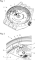
- Watch 2 shown in Figures 1 and 2 without the bottom of the case and without the oscillating mass of the mechanical movement 4, incorporates an actuator formed by an electromechanical device 6 and an electrical control circuit 8.
- the electromechanical device comprises an electromagnetic system 10 and a mechanical element 22 which is movable in translation, along an axis Z, and associated with the electromagnetic system.
- the electromagnetic system 10 is formed by a permanent magnet 12 and a coil 14, the latter being carried by a flexible member 16, forming the electromechanical device, while the permanent magnet is carried by a support 18 of this flexible member. It will be noted that at the Figure 2 , the part of the support to which the flexible member 16 is fixed by means of two screws has been removed to reveal the permanent magnet.
- the flexible member 16 is formed at least partially by an elastic element 20.
- This flexible member comprises the mechanical element 22 which may be part of this elastic element or be fixed to it.
- the elastic element is advantageously formed by an elastic blade 20 which is folded back on itself so as to increase its length for a given size of the electromechanical device 6.
- the flexible member is formed by a base fixed to the support 18, the elastic blade 20, a flat disc 21 at the free end of the elastic blade and the mechanical element 22 which is integral with the flat disc and which is connected to the latter via a bent part.
- the mechanical element 22 forms a sort of pad making it possible to apply mechanical braking pulses to the felloe 24 by contact between this pad and the underside of this felloe. To do this, it is necessary for the mechanical element 22 to be able to exert a certain force on a lower surface of the felloe 24, which is made possible by the actuator described here.
- the mechanical element 22 is therefore part of the flexible member 16 although it is not itself necessarily flexible, but it is connected to the free end of the elastic element 20, directly or by another part of the flexible member, so that it can undergo a displacement when the elastic element is subjected to a deformation force generated by the electromagnetic system 10, as shown in FIG. Figure 3B .
- the actuator further comprises a magnetic element arranged in a fixed position relative to the axis of rotation of the balance of the mechanical resonator and arranged so as to be able to interact with the permanent magnet 12 to generate between them a magnetic force which is exerted on the mechanical element 22 when the latter is in its rest position and which defines a restoring force of this mechanical element towards its rest position over at least an initial part of the distance from the rest position to the contact position.
- the magnetic element has a stable position relative to the coil when the actuator is in a functional configuration allowing it to be actuated.
- the magnetic element 26 is integral with the coil 14.
- the magnetic force has a direction opposite to that of the electromagnetic force, which is generated in the electromagnetic system 10 when the coil 14 is energized, over at least an initial part of the distance from the rest position to the contact position. Then, the magnetic force has an intensity which decreases, over said at least an initial part, when the mechanical element 22 moves away from the rest position and which is less than the intensity which the magnetic force presents. electromagnetic repulsion for any position of the mechanical element in said at least one initial part.
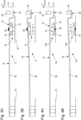
- the magnetic element 26 is aligned with the central axis of the permanent magnet 12 when the mechanical element 22 is in the rest position, as shown in Figure 3A .
- the magnetic element is formed by an element 26 made of a ferromagnetic material, hereinafter called ferromagnetic element.
- the permanent magnet 12 has a disc shape, more generally a solid wafer shape.
- the magnetic element 26 has a disc shape, more generally a solid wafer shape.
- the magnetic force provided is very effective in stabilizing the flexible member 16 and thus the mechanical element 22 in the rest position.
- the magnetic element 26 is arranged so that it exerts a force of increasing intensity when the mechanical element approaches the rest position, unlike the elastic force of the flexible member.
- the flexible member is subjected to a magnetic force which tends to maintain it in its rest position and to strongly recall it towards it in the event of an external disturbance which may momentarily move it away from the rest position, by limiting the distance of the mechanical element 22 and also the amplitude of any rebounds which the flexible member may exhibit following such a distance.
- the magnetic force is relatively significant when the mechanical element 22 is in the rest position and close to it. This will be seen even more precisely in the description below of a second variant.
- FIG. 4A and 4B a second variant of the first embodiment is shown.
- This variant is distinguished from the first variant by a spatial inversion of the electromagnetic system 10A of the electromechanical device 6A.
- the permanent magnet 12 is carried by the elastic blade 20 on the side of its free end while the coil 14 is fixed to the support 18 with the magnetic element 26 arranged in the interior space of the coil.
- An advantage of this second variant lies in the fact that the coil undergoes neither movement nor shock against the rim 24 of the balance when the electromagnetic system 10A is activated. This makes it possible not to stress the electrical connections of the coil to the electrical control circuit, and therefore to avoid a break in these connections.
- this second variant is more sensitive to external magnetic fields than the first variant since the permanent magnet is carried by a movable part of the flexible member.
- the dimensions of the magnetic element are smaller than those of the permanent magnet 12.
- the coil has an outer diameter of 2.4 mm, an inner diameter of 0.9 mm and a height of 0.4 mm.
- the permanent magnet 12 has a diameter of 2.0 mm and a height of 1.0 mm.
- the ferromagnetic element 26 has a diameter of 0.15 mm and a thickness of 0.05 mm. It will be noted that these values can be optimized depending on the type of magnet selected, the distance between the permanent magnet and the ferromagnetic element, the electrical pulses that the electrical control circuit provides to the electromagnetic system, the desired dynamics for the mechanical element 22 and other parameters.
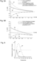
- FIG. 5B introduces the mechanical restoring force, defined by the force exerted by the elastic blade 20 when it moves away from its rest position, which is given by curve 36, which is determined by the coefficient of elasticity of the elastic blade.
- curve 38 represents the total restoring force, resulting from the addition of the magnetic force (curve 30) and the mechanical restoring force (curve 36), as a function of the displacement of the mechanical element along the Z axis. It is observed that the total restoring force increases in intensity from the contact position to the rest position where it is maximum, and this thanks to the ferromagnetic element.
- curve 40 gives the overall force exerted on the flexible member 16, at the level of the mechanical element 22, as a function of the displacement of the mechanical element along the Z axis. Although this overall force changes mathematical sign and therefore direction over the range of displacement represented, it nevertheless remains positive over the entire distance between the rest position and the expected contact position.
- a preload of the elastic element is provided in the rest position.
- Such a preload can be provided either positive, so that the mechanical restoring force (elastic force) is driving over an initial part of the distance from the rest position to the contact position, or negative so that the mechanical restoring force is greater than that occurring in the variant shown over the entire said distance.
- a preload of the flexible member at rest thus makes it possible to adjust the total restoring force, in particular for the rest position and close to it, and therefore the quantity of energy to be supplied to the flexible member via the electromagnetic system during a braking pulse.
- the ferromagnetic element in the two variants described previously is replaced by a second permanent magnet having a magnetic axis parallel to that of the permanent magnet 12 and the same polarity than this magnet.
- the first magnet 12 and the second magnet for stabilizing the flexible member in the rest position are in magnetic attraction for any position of the mechanical element between the rest position, including, and the contact position.
- the second permanent magnet has a solid wafer shape, in particular a disc shape.
- FIG. 7 is an introduction to the second embodiment which will be described below.
- This figure shows the electromagnetic system 10 described previously.
- the magnetic field lines generated by the permanent magnet 12 are shown, these magnetic field lines defining two zones, Zone 1 and Zone 2, for a second magnet placed at the periphery of the magnet 12 and having a magnetic axis of the same direction. If the two magnets have the same polarity along said direction (Z axis), then they have a magnetic attraction in Zone 1 and a magnetic repulsion in Zone 2.
- This observation is the basis of the second embodiment shown in Figures 8A to 8C .
- the magnetic element for stabilizing the rest position of the flexible member 16 is a second permanent magnet 50 which has an annular shape defining a central circle.
- the diameter of this central circle is conventionally given by the intersection of the two diagonals of this cross-section.
- This second embodiment is distinguished from the previous one essentially by the fact that the magnetic element of the electromechanical device 6B is a second permanent magnet, which has an annular shape defining a central circle, or by the fact that this magnetic element is constituted by a plurality of permanent magnets arranged on the along a geometric circle.
- the central circle has a diameter which is greater than the outer diameter of the first permanent magnet and it is, when the flexible member is in the rest position ( Figures 8A and 8C ), centered on the central axis of the first permanent magnet 12.
- the diameter of the central circle is selected so that the magnetic force between the first permanent magnet 12 and the second annular permanent magnet 50 has a reversal of direction during a movement of the mechanical element 22 from the rest position to the position of contact with the balance 24.
- the annular permanent magnet 50 is located in Zone 2 when the flexible member is at rest, so that the magnetic force between the two magnets is in attraction, whereas in the contact position, the annular permanent magnet is in Zone 1 so that the two magnets are then in magnetic repulsion.
- the annular permanent magnet 50 plays its role of returning it to the rest position well.
- this annular magnet crosses the boundary between Zone 2 and Zone 1 and thus the magnetic force becomes positive and consequently a driving force, which modifies the dynamics of the movement of the mechanical element 22 relative to the first embodiment.
- the position along the Z axis of the annular magnet 50 can easily be adjusted. It is in particular possible for the central circle to be at the level of the upper surface of the first magnet 12, or even below.
- a part 48 made of non-magnetic material forms a core of the coil 14 and a flange which is surrounded by the magnet 50. This part 48 undergoes the impact between the flexible member 16 and the magnet 12.
- Its material can thus be selected to preserve the first magnet, this material preferably having a good capacity for absorbing energy during the impact between the part 48 and the first magnet during a return of the mechanical element to the rest position after it has struck against the rim 24 of the balance during a braking impulse.
- the annular magnet 50 is replaced by a plurality of separate permanent magnets which are arranged along a geometric circle.
- it is the geometric circle which has a diameter greater than the outer diameter of the first permanent magnet 12 and which is, when the flexible member is in the rest position, centered on the central axis of the first permanent magnet.
- the diameter of the geometric circle is selected so that the magnetic force between the first permanent magnet and the plurality of permanent magnets has a reversal of direction during the movement of the mechanical element between the rest position and the contact position.
- the plurality of magnets may consist of two small magnets arranged diametrically opposite each other and preferably oriented orthogonally to the direction of the end portion of the elastic blade 20 connected to the disc 21 supporting the coil and the part 48.
- four magnets are provided distributed regularly along the geometric circle. These magnets may be housed in cavities in the flange of the contact part with the first magnet.
- This third embodiment is characterized by an electromagnetic system 10C whose permanent magnet 52, called the first permanent magnet or first magnet, has an annular shape and by a magnetic element constituted by a permanent magnet 54, called the second permanent magnet or second magnet, having a solid wafer shape, in particular a disc shape.
- the second magnet is arranged so as to be aligned on a central axis of the first magnet when the mechanical element 22 is in the rest position ( Figures 9A and 9C ).
- This second magnet is placed in a housing of a support 48A forming a core for the coil 14 and in addition a flange which covers the lower surface of this coil, as in the second mode of realization.
- the zero position along the Z axis is defined by the upper surface of the first magnet and the rest position of the flexible member 16 corresponds to a positioning of the second magnet, which is movable synchronously with the mechanical element 22, in which its lower surface is substantially at the zero position.
- Figure 9B shows the electromechanical device 6C of the actuator considered in a situation/state where the flexible member, in particular its mechanical element, is in the position of contact with the balance.
- FIGS 10A and 10B is partially shown a second variant embodiment which has an arrangement of the first and second magnets which is similar to that of the first variant given in Figures 9A to 9C . Thus the interaction between these two magnets is identical in both variants.
- the support 48B of the second magnet in the second variant only forms a non-magnetic core for the coil 14 while the support 48A of the first variant also has a flange covering the lower surface of the coil.
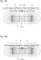
- Figures 10A and 10B the magnetic field lines of the first annular magnet and the second magnet have been partially represented.
- the interior space of the first magnet 52 defines a central void of cylindrical shape.
- the annular shape of the first magnet has the particularity that its magnetic field lines inside the cylindrical central void have a direction opposite to that of the magnetic field in the magnet itself.
- a Zone 3 encompassing the interior space and two complementary zones extending respectively on either side of this interior space, the direction of the magnetic field generated by the first magnet is opposite, along the Z axis, to the direction of the magnetic field of this first magnet in a zone extending Zone 3 above said interior space.
- FIG 10A partially shows the electromechanical device 6C, in particular the disc 21 of the flexible member 16, the electromagnetic system 10C and the additional magnetic element 54, in a situation corresponding to that of the Figure 9B where the flexible member, in particular its mechanical element, is in the contact position.
- the second magnet which has a polarity opposite to that of the first annular magnet (i.e. between the lower surface and the upper surface of this first magnet), undergoes a magnetic repulsion.
- Figure 10B partially shows the electromechanical device 6C in a situation corresponding to that of the Figures 9A and 9C where the flexible member is in its rest position.
- the second magnet 54 is located in Zone 3 and it then undergoes a magnetic attraction from the first annular magnet.
- the reversal of the magnetic force during a movement of the mechanical element 22 between the rest position and the position of contact with the rim 24 of the balance wheel therefore changes the dynamics of the movement of this mechanical element during an electrical pulse supplied to the coil 14, which generates an electromagnetic force given by the curve 62.
- the total magnetic force (addition of the magnetic force and the electromagnetic force during an activation of the electromagnetic system 10C) is represented by the curve 64. It is observed in the example given that this total magnetic force varies relatively little over the displacement distance of the magnetic element.
- the various elements intervening first in the total restoring force (curve 66) and then in the overall force (curve 70) are selected and arranged so that the overall force is positive over the entire travel distance and the total restoring force is negative over the entire travel distance, that is to say for any position between position rest position and the contact position.
- the first annular magnet, the second permanent magnet and the elastic element are configured and arranged in such a way that the sum of the mechanical restoring force and the magnetic force has, over the entire distance that the mechanical element 22 can travel, a direction opposite to the direction of movement of this mechanical element from the rest position to the contact position, so as to form over this entire distance a total restoring force of the mechanical element towards the rest position.
- a fourth embodiment of the invention will finally be described.
- the references already described in detail previously will not be described again.
- This fourth embodiment is essentially distinguished from the previous embodiment by the fact that the magnetic element 74 of the electromechanical device is made of a ferromagnetic material and that this ferromagnetic element 74 is positioned along the Z axis at a different level.
- a circular tube 76 is provided around the electromagnetic system 10D in the rest position.
- the cylindrical tube is arranged so that the disc 21 of the flexible member bears against the upper surface of this cylindrical tube when the flexible member is at rest, the height of the cylindrical tube being selected so that the coil 14 is at a distance from the permanent magnet 52 in the rest position of the flexible member.
- the ferromagnetic element 74 has a solid pancake shape, in particular a disc shape, and is arranged to be aligned with a central axis of the annular permanent magnet when the mechanical element is in the rest position.
- the ferromagnetic element is fixed to a projecting portion of a support 78 forming a core of the coil 14.
- the ferromagnetic element is arranged so as to be positioned at least partially in an interior space of the annular permanent magnet 52 when the mechanical element is in the rest position.
- FIGs 13A and 13B are given two graphs with curves representing the same forces, as a function of the displacement of the ferromagnetic element, as in the graphs of the Figures 11A and 11B .
- Curve 82 of the electromagnetic force is identical to curve 62.
- the annular permanent magnet 52, the ferromagnetic element 74 and the elastic element 20 are configured and arranged so that the sum of the mechanical restoring force and the magnetic force has, over the entire distance that the mechanical element 22 can travel, a direction opposite to the direction of movement of this mechanical element from the rest position to the contact position, so as to form over the entire said displacement distance a total restoring force of the mechanical element towards the rest position.
- the overall force it is not necessary, although preferred, for the overall force to be positive up to the contact position.
- the mechanical element 22 sets off in the opposite direction towards the rest position with a certain energy.
- the mechanical element stores a certain kinetic energy which can allow it to cross a certain intermediate section where the total restoring force would have momentarily changed direction.
Landscapes
- Physics & Mathematics (AREA)
- General Physics & Mathematics (AREA)
- Engineering & Computer Science (AREA)
- Electromagnetism (AREA)
- Power Engineering (AREA)
- Reciprocating, Oscillating Or Vibrating Motors (AREA)
Claims (16)
- Uhrmachereistück (2), das ein Wirkglied beinhaltet, das aus einer elektromechanischen Vorrichtung (6; 6A; 6B; 6C; 6D), die ein elektromagnetisches System (10; 10A; 10B; 10C; 10D), sowie ein mechanisches Element (22) umfasst, das translatorisch beweglich und dem elektromagnetischen System zugeordnet ist, und einem elektrischen Steuerkreis (8) gebildet ist, wobei das elektromagnetische System durch einen Permanentmagneten (12; 52) und eine Spule (14) gebildet wird, von denen eines von den beiden von einem flexiblen Organ (16) der elektromechanischen Vorrichtung, und das andere von einem Träger (18) dieses flexiblen Organs getragen wird, wobei das mechanische Element durch das flexible Organ gebildet wird und das Wirkglied angeordnet ist, um als Reaktion auf ein elektrisches Aktivierungssignal, das von der elektrischen Steuerschaltung erzeugt, und der Spule bereitgestellt wird, um eine elektromagnetische Kraft zwischen dieser Spule und dem Permanentmagneten zu ergeben, eine Bewegung des mechanischen Elements aus einer Ruheposition, in der vorgesehen ist, dass das mechanische Element in Abwesenheit einer Aktivierung des elektromagnetischen Systems verbleibt, bis zu einer Kontaktposition mit einem bestimmten Teil (24) des Uhrmachereistücks zu ermöglichen; wobei das flexible Organ zumindest teilweise durch ein elastisches Element (20) gebildet wird, das angeordnet ist, um eine mechanische Rückstellkraft des mechanischen Elements in Richtung der Ruheposition über zumindest einen Hauptteil der Distanz zu ergeben, die das mechanische Element, wenn die elektrische Steuerschaltung das elektrische Aktivierungssignal erzeugt, zwischen der Ruheposition und der Kontaktposition zurücklegen kann, wobei diese Kontaktposition den zumindest einen Hauptteil der Distanz beendet;
wobei das Wirkglied weiter ein magnetisches Element (26; 50; 54; 74) umfasst, das angeordnet ist, um mit dem Permanentmagneten (12; 52) zusammenwirken zu können, um dazwischen eine magnetische Kraft zu ergeben, die auf das mechanische Element einwirkt, wenn sich dieses letztere in der Ruheposition befindet, wobei diese magnetische Kraft eine entgegengesetzte Richtung zu jener der elektromagnetischen Kraft über mindestens einen anfänglichen Teil der Distanz aus der Ruheposition aufweist, und eine Intensität, die über den mindestens einen anfänglichen Teil abnimmt, wenn sich das mechanische Element aus der Ruheposition entfernt, und die geringer ist als die Intensität, die die elektromagnetische Kraft für jede beliebige Position des mechanischen Elements in dem mindestens einen anfänglichen Teil aufweist. - Uhrmachereistück nach Anspruch 1, dadurch gekennzeichnet, dass das magnetische Element (26; 74) aus einem ferromagnetischen Werkstoff besteht.
- Uhrmachereistück nach Anspruch 1, wobei der Permanentmagnet ein erster Magnet ist, dadurch gekennzeichnet, dass das magnetische Element (50; 54) durch einen zweiten Permanentmagneten gebildet wird, der in magnetischer Anziehung mit dem ersten Magneten angeordnet ist, wenn sich das mechanische Element (22) in der Ruheposition befindet.
- Uhrmachereistück nach Anspruch 2, dadurch gekennzeichnet, dass der Permanentmagnet (12) eine Form einer vollen Rolle, insbesondere eine Scheibenform, aufweist; und dadurch, dass das magnetische Element angeordnet ist, um auf einer Mittelachse des Permanentmagneten ausgerichtet zu sein, wenn sich das mechanische Element in der Ruheposition befindet.
- Uhrmachereistück nach Anspruch 3, dadurch gekennzeichnet, dass der erste Permanentmagnet (12) eine Form einer vollen Rolle, insbesondere eine Scheibenform, aufweist; und dadurch, dass das magnetische Element angeordnet ist, um auf einer Mittelachse des ersten Permanentmagneten ausgerichtet zu sein, wenn sich das mechanische Element in der Ruheposition befindet.
- Uhrmachereistück nach Anspruch 4, dadurch gekennzeichnet, dass das ferromagnetische Element (26; 74) eine Form einer vollen Rolle, insbesondere eine Scheibenform, aufweist.
- Uhrmachereistück nach Anspruch 5, dadurch gekennzeichnet, dass der zweite Permanentmagnet (54) eine Form einer vollen Rolle, insbesondere eine Scheibenform, aufweist.
- Uhrmachereistück nach Anspruch 5, dadurch gekennzeichnet, dass das magnetische Element (50) aus dem zweiten Permanentmagneten besteht, der eine Ringform aufweist, die einen zentralen Kreis definiert, oder aus einer Vielzahl von Permanentmagneten, die entlang eines geometrischen Kreises angeordnet sind; dadurch, dass der zentrale Kreis oder der geometrische Kreis einen Durchmesser aufweist, der größer als der Außendurchmesser des ersten Permanentmagneten (12) ist und, wenn sich das flexible Element in der Ruheposition befindet, auf der Mittelachse des ersten Permanentmagneten zentriert ist; und dadurch, dass der Durchmesser des zentralen Kreises oder des geometrischen Kreises so gewählt ist, dass die Magnetkraft zwischen dem ersten Permanentmagneten und dem zweiten Permanentmagneten, bzw. der Vielzahl von Permanentmagneten bei der Bewegung des mechanischen Elements (22) aus der Ruheposition bis zur Kontaktposition eine Richtungsumkehr aufweist.
- Uhrmachereistück nach Anspruch 2, dadurch gekennzeichnet, dass der Permanentmagnet (52) eine Ringform aufweist.
- Uhrmachereistück nach Anspruch 3, dadurch gekennzeichnet, dass der erste Permanentmagnet (52) eine Ringform aufweist.
- Uhrmachereistück nach Anspruch 9, dadurch gekennzeichnet, dass das ferromagnetische Element (74) eine Form einer vollen Rolle, insbesondere eine Scheibenform, aufweist; und dadurch, dass dieses ferromagnetische Element angeordnet ist, um auf einer Mittelachse des Permanentmagneten ausgerichtet zu sein, wenn sich das mechanische Element in seiner Ruheposition befindet.
- Uhrmachereistück nach Anspruch 11, dadurch gekennzeichnet, dass das ferromagnetische Element angeordnet ist, um zumindest teilweise in einem Innenraum des ringförmigen Permanentmagneten positioniert zu sein, wenn sich das mechanische Element in der Ruheposition befindet.
- Uhrmachereistück nach Anspruch 11 oder 12, dadurch gekennzeichnet, dass der Permanentmagnet (52), das ferromagnetische Element (74) und das elastische Element (20) konfiguriert und angeordnet sind, sodass die Summe der mechanischen Rückstellkraft und der magnetischen Kraft über die gesamte Distanz, die das mechanische Element zurücklegen kann, eine Richtung aufweist, die der Richtung der Bewegung dieses mechanischen Elements von der Ruheposition bis zur Kontaktposition entgegengesetzt ist, um über die gesamte Distanz eine Gesamtrückstellkraft des mechanischen Elements in die Ruheposition zu bilden.
- Uhrmachereistück nach Anspruch 10, dadurch gekennzeichnet, dass der zweite Permanentmagnet (54) eine Form einer vollen Rolle, insbesondere eine Scheibenform, aufweist; und dadurch, dass der zweite Permanentmagnet angeordnet ist, um auf einer Mittelachse des ersten Permanentmagneten ausgerichtet zu sein, wenn sich das mechanische Element in der Ruheposition befindet.
- Uhrmachereistück nach Anspruch 14, dadurch gekennzeichnet, dass der zweite Permanentmagnet angeordnet ist, sodass die magnetische Kraft zwischen dem ersten Permanentmagneten (52) und dem zweiten Permanentmagneten (54) bei der Bewegung des mechanischen Elements (22) aus der Ruheposition bis zur Kontaktposition eine Richtungsumkehr aufweist.
- Uhrmachereistück nach Anspruch 15, dadurch gekennzeichnet, dass der erste Permanentmagnet, der zweite Permanentmagnet und das elastische Element (20) konfiguriert und angeordnet sind, sodass die Summe der mechanischen Rückstellkraft und der magnetischen Kraft über die gesamte Distanz, die das mechanische Element (22) zurücklegen kann, eine Richtung aufweist, die der Richtung der Bewegung dieses mechanischen Elements von der Ruheposition bis zur Kontaktposition entgegengesetzt ist, um über die gesamte Distanz eine Gesamtrückstellkraft des mechanischen Elements in die Ruheposition zu bilden.
Priority Applications (3)
| Application Number | Priority Date | Filing Date | Title |
|---|---|---|---|
| US17/673,146 US12013668B2 (en) | 2021-03-23 | 2022-02-16 | Timepiece incorporating an actuator comprising an electromechanical device |
| JP2022024679A JP7353403B2 (ja) | 2021-03-23 | 2022-02-21 | 電気機械デバイスを備えるアクチュエーターを搭載する計時器 |
| CN202210289746.3A CN115113511B (zh) | 2021-03-23 | 2022-03-23 | 结合有包括机电装置的致动器的时计 |
Applications Claiming Priority (1)
| Application Number | Priority Date | Filing Date | Title |
|---|---|---|---|
| EP21164369 | 2021-03-23 |
Publications (2)
| Publication Number | Publication Date |
|---|---|
| EP4063973A1 EP4063973A1 (de) | 2022-09-28 |
| EP4063973B1 true EP4063973B1 (de) | 2025-03-26 |
Family
ID=75203048
Family Applications (1)
| Application Number | Title | Priority Date | Filing Date |
|---|---|---|---|
| EP21205508.1A Active EP4063973B1 (de) | 2021-03-23 | 2021-10-29 | Uhr mit integriertem stellglied, das eine elektromechanische vorrichtung umfasst |
Country Status (4)
| Country | Link |
|---|---|
| US (1) | US12013668B2 (de) |
| EP (1) | EP4063973B1 (de) |
| JP (1) | JP7353403B2 (de) |
| CN (1) | CN115113511B (de) |
Family Cites Families (9)
| Publication number | Priority date | Publication date | Assignee | Title |
|---|---|---|---|---|
| GB932400A (en) * | 1959-07-11 | 1963-07-24 | Movado Montres | Electromagnetic system for the maintenance of the movement of a rotating member such as a balance of a timepiece |
| JPH0922568A (ja) * | 1995-07-06 | 1997-01-21 | Hitachi Metals Ltd | ヘッドアーム用双安定磁気ラッチング装置 |
| EP3246764B1 (de) * | 2016-05-18 | 2019-01-23 | Montres Breguet S.A. | Stossdämpfende vorrichtung für uhrwerk |
| EP3373081B1 (de) * | 2017-03-06 | 2021-05-26 | Montres Breguet S.A. | Uhrwerk, das mit einer vorrichtung zur positionierung eines mobilen elements in einer vielzahl von diskreten positionen ausgestattet ist |
| JP6826673B2 (ja) * | 2017-03-28 | 2021-02-03 | ザ・スウォッチ・グループ・リサーチ・アンド・ディベロップメント・リミテッド | 調整デバイスにより動作が強化されるムーブメントを備えた機械式計時器 |
| US11300929B2 (en) | 2017-03-28 | 2022-04-12 | The Swatch Group Research And Development Ltd | Timepiece comprising a mechanical movement which running is enhanced by a regulation device |
| CH715091A2 (fr) * | 2018-06-07 | 2019-12-30 | Swatch Group Res & Dev Ltd | Pièce d'horlogerie comprenant un mouvement mécanique dont la marche est régulée par un dispositif électromécanique. |
| EP3620867B1 (de) * | 2018-09-04 | 2022-01-05 | The Swatch Group Research and Development Ltd | Uhr, die einen mechanischen oszillator umfasst, dessen durchschnittliche frequenz mit der eines elektronischen referenzoszillators synchronisiert ist |
| CH715399A2 (fr) * | 2018-09-27 | 2020-03-31 | Swatch Group Res & Dev Ltd | Pièce d'horlogerie comprenant un oscillateur mécanique associé à un dispositif électronique de régulation de sa fréquence moyenne. |
-
2021
- 2021-10-29 EP EP21205508.1A patent/EP4063973B1/de active Active
-
2022
- 2022-02-16 US US17/673,146 patent/US12013668B2/en active Active
- 2022-02-21 JP JP2022024679A patent/JP7353403B2/ja active Active
- 2022-03-23 CN CN202210289746.3A patent/CN115113511B/zh active Active
Also Published As
| Publication number | Publication date |
|---|---|
| US20220308527A1 (en) | 2022-09-29 |
| JP2022151644A (ja) | 2022-10-07 |
| JP7353403B2 (ja) | 2023-09-29 |
| US12013668B2 (en) | 2024-06-18 |
| EP4063973A1 (de) | 2022-09-28 |
| CN115113511B (zh) | 2024-11-12 |
| CN115113511A (zh) | 2022-09-27 |
Similar Documents
| Publication | Publication Date | Title |
|---|---|---|
| EP2282240B1 (de) | Chronographmodul für Armbanduhr | |
| EP2496990B1 (de) | Einstellungselement für eine armbanduhr sowie uhr mit einem solchen einstellungselement | |
| EP2487547A1 (de) | Regulator einer Triebfeder eines Uhrwerks oder eines Schlagwerks | |
| EP2891930A2 (de) | Vorrichtung zur Regulierung der Winkelgeschwindigkeit einer Triebfeder in einem Uhrwerk, das einen magnetischen Hemmungsmechanismus umfasst | |
| EP3382470B1 (de) | Oszillator einer uhr mit flexiblem zapfen | |
| EP3548973A1 (de) | Vorrichtung für eine uhr, uhrwerk und uhr mit solch einer vorrichtung | |
| EP2808745B1 (de) | Schlagwerk mit Mitteln zur Auswahl des Vibrationsmodus einer Tonfeder | |
| EP3106933B1 (de) | Magnetischer schwenkeinrichtung einer welle in einem uhrwerk | |
| CH709052A2 (fr) | Balancier-spiral, mouvement et pièce d'horlogerie. | |
| EP2911015B1 (de) | Natürliche Hemmung | |
| WO2012034810A2 (fr) | Echappement blancpain à ancre amélioré pour mouvement d'horlogerie | |
| EP3835886A1 (de) | Armbanduhr mit steuerungsorgan | |
| EP2463731A1 (de) | Schlagwerkmechanismus einer Armbanduhr | |
| CH718124B1 (fr) | Dispositif à ressort-spiral pour mécanisme résonateur d'horlogerie muni de moyens d'ajustement de la rigidité. | |
| EP4063973B1 (de) | Uhr mit integriertem stellglied, das eine elektromechanische vorrichtung umfasst | |
| CH718445A2 (fr) | Pièce d'horlogerie incorporant un actuateur comprenant un dispositif électromécanique. | |
| EP3430479A1 (de) | Vorrichtung für eine uhr, uhrwerk und uhr mit solch einer vorrichtung | |
| EP3944027B1 (de) | Tragbares gerät, insbesondere armbanduhr, das mit einer stromquellevorrichtung mit einem elektromechanischen wandler ausgestattet ist | |
| EP2362279A1 (de) | Schlagwerkmechanismus einer Armbanduhr mit aktiver Dämpfungsgegenfeder | |
| WO2017157712A1 (fr) | Mécanisme pour pièce d'horlogerie, mouvement horloger et pièce d'horlogerie comprenant un tel mécanisme | |
| CH719059B1 (fr) | Dispositif horloger comprenant un marteau comportant deux parties reliées entre elles par un organe de guidage flexible. | |
| EP2497095A1 (de) | Einstellungselement für eine armbanduhr sowie uhr mit einem solchen einstellungselement | |
| EP3982379B1 (de) | Mikro-schalter mit solenoid mit magnetischem rückfluss | |
| EP4105733B1 (de) | Perkussionsschlagwerk, insbesondere für uhren | |
| EP3882713B1 (de) | Uhrwerk, das mit einer uhrhemmung mit einem magnetischen system ausgestattet ist |
Legal Events
| Date | Code | Title | Description |
|---|---|---|---|
| PUAI | Public reference made under article 153(3) epc to a published international application that has entered the european phase |
Free format text: ORIGINAL CODE: 0009012 |
|
| STAA | Information on the status of an ep patent application or granted ep patent |
Free format text: STATUS: THE APPLICATION HAS BEEN PUBLISHED |
|
| AK | Designated contracting states |
Kind code of ref document: A1 Designated state(s): AL AT BE BG CH CY CZ DE DK EE ES FI FR GB GR HR HU IE IS IT LI LT LU LV MC MK MT NL NO PL PT RO RS SE SI SK SM TR |
|
| STAA | Information on the status of an ep patent application or granted ep patent |
Free format text: STATUS: REQUEST FOR EXAMINATION WAS MADE |
|
| 17P | Request for examination filed |
Effective date: 20230328 |
|
| RBV | Designated contracting states (corrected) |
Designated state(s): AL AT BE BG CH CY CZ DE DK EE ES FI FR GB GR HR HU IE IS IT LI LT LU LV MC MK MT NL NO PL PT RO RS SE SI SK SM TR |
|
| P01 | Opt-out of the competence of the unified patent court (upc) registered |
Effective date: 20230615 |
|
| GRAP | Despatch of communication of intention to grant a patent |
Free format text: ORIGINAL CODE: EPIDOSNIGR1 |
|
| STAA | Information on the status of an ep patent application or granted ep patent |
Free format text: STATUS: GRANT OF PATENT IS INTENDED |
|
| INTG | Intention to grant announced |
Effective date: 20241206 |
|
| GRAS | Grant fee paid |
Free format text: ORIGINAL CODE: EPIDOSNIGR3 |
|
| GRAA | (expected) grant |
Free format text: ORIGINAL CODE: 0009210 |
|
| STAA | Information on the status of an ep patent application or granted ep patent |
Free format text: STATUS: THE PATENT HAS BEEN GRANTED |
|
| AK | Designated contracting states |
Kind code of ref document: B1 Designated state(s): AL AT BE BG CH CY CZ DE DK EE ES FI FR GB GR HR HU IE IS IT LI LT LU LV MC MK MT NL NO PL PT RO RS SE SI SK SM TR |
|
| REG | Reference to a national code |
Ref country code: GB Ref legal event code: FG4D Free format text: NOT ENGLISH |
|
| REG | Reference to a national code |
Ref country code: CH Ref legal event code: EP |
|
| REG | Reference to a national code |
Ref country code: DE Ref legal event code: R096 Ref document number: 602021028063 Country of ref document: DE |
|
| REG | Reference to a national code |
Ref country code: IE Ref legal event code: FG4D Free format text: LANGUAGE OF EP DOCUMENT: FRENCH |
|
| PG25 | Lapsed in a contracting state [announced via postgrant information from national office to epo] |
Ref country code: RS Free format text: LAPSE BECAUSE OF FAILURE TO SUBMIT A TRANSLATION OF THE DESCRIPTION OR TO PAY THE FEE WITHIN THE PRESCRIBED TIME-LIMIT Effective date: 20250626 |
|
| PG25 | Lapsed in a contracting state [announced via postgrant information from national office to epo] |
Ref country code: FI Free format text: LAPSE BECAUSE OF FAILURE TO SUBMIT A TRANSLATION OF THE DESCRIPTION OR TO PAY THE FEE WITHIN THE PRESCRIBED TIME-LIMIT Effective date: 20250326 |
|
| REG | Reference to a national code |
Ref country code: LT Ref legal event code: MG9D |
|
| PG25 | Lapsed in a contracting state [announced via postgrant information from national office to epo] |
Ref country code: NO Free format text: LAPSE BECAUSE OF FAILURE TO SUBMIT A TRANSLATION OF THE DESCRIPTION OR TO PAY THE FEE WITHIN THE PRESCRIBED TIME-LIMIT Effective date: 20250626 |
|
| PG25 | Lapsed in a contracting state [announced via postgrant information from national office to epo] |
Ref country code: HR Free format text: LAPSE BECAUSE OF FAILURE TO SUBMIT A TRANSLATION OF THE DESCRIPTION OR TO PAY THE FEE WITHIN THE PRESCRIBED TIME-LIMIT Effective date: 20250326 |
|
| PG25 | Lapsed in a contracting state [announced via postgrant information from national office to epo] |
Ref country code: LV Free format text: LAPSE BECAUSE OF FAILURE TO SUBMIT A TRANSLATION OF THE DESCRIPTION OR TO PAY THE FEE WITHIN THE PRESCRIBED TIME-LIMIT Effective date: 20250326 |
|
| PG25 | Lapsed in a contracting state [announced via postgrant information from national office to epo] |
Ref country code: GR Free format text: LAPSE BECAUSE OF FAILURE TO SUBMIT A TRANSLATION OF THE DESCRIPTION OR TO PAY THE FEE WITHIN THE PRESCRIBED TIME-LIMIT Effective date: 20250627 Ref country code: BG Free format text: LAPSE BECAUSE OF FAILURE TO SUBMIT A TRANSLATION OF THE DESCRIPTION OR TO PAY THE FEE WITHIN THE PRESCRIBED TIME-LIMIT Effective date: 20250326 |
|
| REG | Reference to a national code |
Ref country code: NL Ref legal event code: MP Effective date: 20250326 |
|
| PG25 | Lapsed in a contracting state [announced via postgrant information from national office to epo] |
Ref country code: NL Free format text: LAPSE BECAUSE OF FAILURE TO SUBMIT A TRANSLATION OF THE DESCRIPTION OR TO PAY THE FEE WITHIN THE PRESCRIBED TIME-LIMIT Effective date: 20250326 |
|
| PG25 | Lapsed in a contracting state [announced via postgrant information from national office to epo] |
Ref country code: SE Free format text: LAPSE BECAUSE OF FAILURE TO SUBMIT A TRANSLATION OF THE DESCRIPTION OR TO PAY THE FEE WITHIN THE PRESCRIBED TIME-LIMIT Effective date: 20250326 |
|
| REG | Reference to a national code |
Ref country code: AT Ref legal event code: MK05 Ref document number: 1779528 Country of ref document: AT Kind code of ref document: T Effective date: 20250326 |
|
| PG25 | Lapsed in a contracting state [announced via postgrant information from national office to epo] |
Ref country code: SM Free format text: LAPSE BECAUSE OF FAILURE TO SUBMIT A TRANSLATION OF THE DESCRIPTION OR TO PAY THE FEE WITHIN THE PRESCRIBED TIME-LIMIT Effective date: 20250326 |
|
| PG25 | Lapsed in a contracting state [announced via postgrant information from national office to epo] |
Ref country code: PT Free format text: LAPSE BECAUSE OF FAILURE TO SUBMIT A TRANSLATION OF THE DESCRIPTION OR TO PAY THE FEE WITHIN THE PRESCRIBED TIME-LIMIT Effective date: 20250728 Ref country code: ES Free format text: LAPSE BECAUSE OF FAILURE TO SUBMIT A TRANSLATION OF THE DESCRIPTION OR TO PAY THE FEE WITHIN THE PRESCRIBED TIME-LIMIT Effective date: 20250326 |
|
| PG25 | Lapsed in a contracting state [announced via postgrant information from national office to epo] |
Ref country code: PL Free format text: LAPSE BECAUSE OF FAILURE TO SUBMIT A TRANSLATION OF THE DESCRIPTION OR TO PAY THE FEE WITHIN THE PRESCRIBED TIME-LIMIT Effective date: 20250326 Ref country code: IT Free format text: LAPSE BECAUSE OF FAILURE TO SUBMIT A TRANSLATION OF THE DESCRIPTION OR TO PAY THE FEE WITHIN THE PRESCRIBED TIME-LIMIT Effective date: 20250326 |
|
| PG25 | Lapsed in a contracting state [announced via postgrant information from national office to epo] |
Ref country code: AT Free format text: LAPSE BECAUSE OF FAILURE TO SUBMIT A TRANSLATION OF THE DESCRIPTION OR TO PAY THE FEE WITHIN THE PRESCRIBED TIME-LIMIT Effective date: 20250326 |
|
| PGFP | Annual fee paid to national office [announced via postgrant information from national office to epo] |
Ref country code: FR Payment date: 20250924 Year of fee payment: 5 |
|
| PG25 | Lapsed in a contracting state [announced via postgrant information from national office to epo] |
Ref country code: EE Free format text: LAPSE BECAUSE OF FAILURE TO SUBMIT A TRANSLATION OF THE DESCRIPTION OR TO PAY THE FEE WITHIN THE PRESCRIBED TIME-LIMIT Effective date: 20250326 |
|
| PG25 | Lapsed in a contracting state [announced via postgrant information from national office to epo] |
Ref country code: RO Free format text: LAPSE BECAUSE OF FAILURE TO SUBMIT A TRANSLATION OF THE DESCRIPTION OR TO PAY THE FEE WITHIN THE PRESCRIBED TIME-LIMIT Effective date: 20250326 |
|
| PG25 | Lapsed in a contracting state [announced via postgrant information from national office to epo] |
Ref country code: SK Free format text: LAPSE BECAUSE OF FAILURE TO SUBMIT A TRANSLATION OF THE DESCRIPTION OR TO PAY THE FEE WITHIN THE PRESCRIBED TIME-LIMIT Effective date: 20250326 |
|
| PG25 | Lapsed in a contracting state [announced via postgrant information from national office to epo] |
Ref country code: IS Free format text: LAPSE BECAUSE OF FAILURE TO SUBMIT A TRANSLATION OF THE DESCRIPTION OR TO PAY THE FEE WITHIN THE PRESCRIBED TIME-LIMIT Effective date: 20250726 |
|
| REG | Reference to a national code |
Ref country code: CH Ref legal event code: U11 Free format text: ST27 STATUS EVENT CODE: U-0-0-U10-U11 (AS PROVIDED BY THE NATIONAL OFFICE) Effective date: 20251101 |
|
| REG | Reference to a national code |
Ref country code: DE Ref legal event code: R097 Ref document number: 602021028063 Country of ref document: DE |
|
| PGFP | Annual fee paid to national office [announced via postgrant information from national office to epo] |
Ref country code: DE Payment date: 20250923 Year of fee payment: 5 |
|
| PG25 | Lapsed in a contracting state [announced via postgrant information from national office to epo] |
Ref country code: DK Free format text: LAPSE BECAUSE OF FAILURE TO SUBMIT A TRANSLATION OF THE DESCRIPTION OR TO PAY THE FEE WITHIN THE PRESCRIBED TIME-LIMIT Effective date: 20250326 |
|
| PGFP | Annual fee paid to national office [announced via postgrant information from national office to epo] |
Ref country code: CH Payment date: 20251101 Year of fee payment: 5 |
|
| PG25 | Lapsed in a contracting state [announced via postgrant information from national office to epo] |
Ref country code: CZ Free format text: LAPSE BECAUSE OF FAILURE TO SUBMIT A TRANSLATION OF THE DESCRIPTION OR TO PAY THE FEE WITHIN THE PRESCRIBED TIME-LIMIT Effective date: 20250326 |
|
| PLBE | No opposition filed within time limit |
Free format text: ORIGINAL CODE: 0009261 |
|
| STAA | Information on the status of an ep patent application or granted ep patent |
Free format text: STATUS: NO OPPOSITION FILED WITHIN TIME LIMIT |
|
| REG | Reference to a national code |
Ref country code: CH Ref legal event code: L10 Free format text: ST27 STATUS EVENT CODE: U-0-0-L10-L00 (AS PROVIDED BY THE NATIONAL OFFICE) Effective date: 20260211 |
|
| 26N | No opposition filed |
Effective date: 20260105 |