EP4068011A1 - Commande de machine, ainsi que procédé de configuration de la commande de machine - Google Patents
Commande de machine, ainsi que procédé de configuration de la commande de machine Download PDFInfo
- Publication number
- EP4068011A1 EP4068011A1 EP21166569.0A EP21166569A EP4068011A1 EP 4068011 A1 EP4068011 A1 EP 4068011A1 EP 21166569 A EP21166569 A EP 21166569A EP 4068011 A1 EP4068011 A1 EP 4068011A1
- Authority
- EP
- European Patent Office
- Prior art keywords
- signals
- machine
- status
- signal
- signal converter
- Prior art date
- Legal status (The legal status is an assumption and is not a legal conclusion. Google has not performed a legal analysis and makes no representation as to the accuracy of the status listed.)
- Withdrawn
Links
Images
Classifications
-
- G—PHYSICS
- G05—CONTROLLING; REGULATING
- G05B—CONTROL OR REGULATING SYSTEMS IN GENERAL; FUNCTIONAL ELEMENTS OF SUCH SYSTEMS; MONITORING OR TESTING ARRANGEMENTS FOR SUCH SYSTEMS OR ELEMENTS
- G05B13/00—Adaptive control systems, i.e. systems automatically adjusting themselves to have a performance which is optimum according to some preassigned criterion
- G05B13/02—Adaptive control systems, i.e. systems automatically adjusting themselves to have a performance which is optimum according to some preassigned criterion electric
- G05B13/0265—Adaptive control systems, i.e. systems automatically adjusting themselves to have a performance which is optimum according to some preassigned criterion electric the criterion being a learning criterion
-
- G—PHYSICS
- G05—CONTROLLING; REGULATING
- G05B—CONTROL OR REGULATING SYSTEMS IN GENERAL; FUNCTIONAL ELEMENTS OF SUCH SYSTEMS; MONITORING OR TESTING ARRANGEMENTS FOR SUCH SYSTEMS OR ELEMENTS
- G05B17/00—Systems involving the use of models or simulators of said systems
- G05B17/02—Systems involving the use of models or simulators of said systems electric
Definitions
- model-predictive controls are often used to control complex machines, such as robots, production plants, gas turbines, wind turbines, internal combustion engines, building services systems or infrastructure systems. These are also often referred to as model predictive control or MPC.
- MPC controller a future behavior of a machine to be controlled is simulated depending on the input variables in order to determine an output signal that optimizes this behavior depending on this. In many cases, however, carrying out a suitable simulation requires considerable computing resources, especially in the case of real-time applications with short response times.
- a data-driven machine learning model can be trained using simulations, which then supplements or replaces the simulative control.
- a control characteristic conveyed by a trained machine learning model is usually hardly analytically comprehensible or interpretable for a user. This can prove particularly problematic when such a controller requires certification.
- a multiplicity of state signals each specifying a state of the machine in a first state space are read in, each of which is assigned a control signal optimized for the respective state.
- the machine can in particular be a robot, a motor, a production plant, a gas turbine, a wind turbine, an internal combustion engine, a building services installation, an infrastructure installation or one of their components.
- a first signal converter is trained on the basis of the multiplicity of status signals to convert status signals from the first status space into a second status space with reduced dimensions compared to this, with a loss of information being minimized.
- minimizing is also understood to mean an approximation to a minimum.
- optimization here and below also means an approximation to an optimum.
- a second signal converter is trained to reproduce corresponding optimized control signals by converting reduced state signals using the conversion rule.
- the machine controller is thus set up to convert a status signal of the machine into a reduced status signal through the trained first signal converter and this into an optimized control signal through the trained second signal converter, by means of which the machine is controlled.
- a machine controller, a computer program product and a preferably non-volatile computer-readable storage medium are provided for carrying out the method according to the invention.
- the method according to the invention and the machine control according to the invention can be carried out or implemented, for example, by means of one or more computers, processors, application-specific integrated circuits (ASIC), digital signal processors (DSP) and/or so-called “Field Programmable Gate Arrays” (FPGA).
- ASIC application-specific integrated circuits
- DSP digital signal processors
- FPGA Field Programmable Gate Arrays
- the invention makes it possible to generate an explicit conversion rule for a dimension-reduced state space, by means of which a machine can be controlled in an optimized manner.
- a conversion rule can in many cases be interpreted, understood and/or assessed with regard to its consequences by a user, in particular as a heuristic rule. In many cases, this enables a flexible analysis, further development and/or certification of a machine control configured in this way.
- behavior of the machine can be simulated for a large number of operating scenarios.
- a control signal can thus be determined for a respective simulated state of the machine, which optimizes a simulated behavior of the machine induced thereby, in particular according to predefined criteria.
- the determined control signal can then be assigned to the corresponding status signal as an optimized control signal.
- the operating scenarios can advantageously include a large number of operating conditions and/or operating states of the machine.
- the operating scenarios can in particular from the operating data of the machine or from a database are extracted. Alternatively or additionally, the operating scenarios can be generated synthetically, in particular on a random basis.
- a behavior of the machine induced thereby can be simulated for a plurality of variants of the control signal. Depending on this, that variant can then be selected as the optimized control signal that leads to a particularly advantageous behavior of the machine. If necessary, a respective optimized control signal can also be generated by means of an interpolation of several advantageous control signal variants.
- the status signals can be converted linearly from the first status space into the second status space by the first signal converter.
- the linear conversion can be carried out in particular by means of a transformation matrix.
- a vector representing a respective status signal can be multiplied by the transformation matrix in order to obtain a vector representing a reduced status signal.
- the matrix elements of the transformation matrix and possibly their number of rows can be optimized as parameters in such a way that the loss of information is minimized.
- the transformation matrix should have significantly more columns than rows.
- the number of lines can also be optimized during optimization in such a way that the loss of information remains acceptable according to a predetermined criterion.
- a criterion that can be specified, for example, is that a reproduction error of the second signal converter does not exceed a specified threshold value.
- a main component analysis can preferably be carried out on the large number of status signals. This allows the first signal converter be set up to map state signals onto the found principal components of the state signals. In this way, both matrix elements of a transformation matrix and their number of rows can be optimized.
- Such a main component analysis is often also referred to as a principal component analysis or PCA. Efficient numerical standard methods, such as methods for singular value decomposition, are available for carrying out a principal component analysis.
- a respective status signal can be evaluated together with the respectively assigned optimized control signal in the main component analysis.
- This proves to be advantageous in many cases, since in this way correlations between status signals and control signals can also be recognized and used for dimension reduction. Such correlations are often given insofar as a specific control signal causes a specific sequence of states in many cases.
- a transformation matrix can advantageously be extended by additional columns for multiplication with a vector representing a control signal. After carrying out the joint principal component analysis, the additional columns of the resulting transformation matrix can then be removed again.
- the discrete control elements can include numeric operators.
- a symbolic regression with the numerical operators can then be carried out to train the second signal converter.
- the numeric operators can each be encoded by a specific operator identifier, in particular by an operator symbol.
- addition, subtraction, multiplication, division, exponentiation, sine function, cosine function or other discrete mathematical or numerical operations can be provided as operators.
- the operators can in this way become a particularly mathematical expression be put together in such a way that a conversion of a reduced state signal based thereon reproduces a corresponding optimized control signal as precisely as possible.
- a polynomial regression can also be carried out to train the second signal converter.
- a so-called ridge polynomial approximation can preferably be used here, which proves to be very advantageous in many cases, particularly in the case of a combination of dimensional reduction and polynomial regression.
- numeric operators can be generated for training the second signal converter and the reduced state signals can be converted into output signals according to a respective sequence.
- a sequence can be determined in which a distance between the output signals and the corresponding optimized control signals is minimized.
- the conversion rule can then be formed using the determined sequence.
- a respective sequence of numerical operators can be represented, encoded or specified in particular as a graph, as an expression tree or as a symbolic mathematical expression. In such a form, an operator sequence or a resulting conversion rule can usually be interpreted particularly well by a user and can therefore continue to be used in a flexible manner.
- a genetic optimization method can be used to train the second signal converter.
- Many, in particular discrete, optimization tasks can be efficiently solved by means of such genetic optimization methods.
- the assembly of the discrete control elements can be efficiently solved as a discrete optimization task.
- a large number of implementations are available for carrying out a genetic optimization method.
- operating condition-specific status signals and/or operating condition-specifically optimized control signals can be read in for different operating conditions of the machine.
- an operating condition can relate to an operating scenario, a secondary condition to be complied with, a limit value to be complied with and/or an operating restriction.
- An operating condition-specific second signal converter can then be trained for the different operating conditions using the respective operating condition-specific status signals and/or operating condition-specific optimized control signals.
- An operating condition of the machine can then be detected and, depending on this, one of the second signal converters specific to the operating condition can be selected for controlling the machine. In this way, a number of second signal converters optimized for different operating conditions can be kept available and used specifically depending on a current operating condition.
- a machine learning module can be trained on the basis of reduced state signals to generate synthetic reduced state signals.
- the synthetic reduced state signals can then be additionally used to train the second signal converter. In this way, the training of the second signal converter can usually be accelerated considerably. In addition, in many cases the influence of statistical outliers in the training data is reduced.
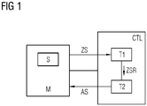
- FIG. 12 illustrates an example of a production robot as the machine M to be controlled.
- the machine M to be controlled can also be a robot, a production system, a motor, a gas turbine, a wind turbine, an internal combustion engine, a building services system, an infrastructure system, a motor vehicle or another machine.
- the machine control CTL can be implemented as part of the production robot M or completely or partially externally to the production robot M. In the present figures, the machine control CTL is shown externally to the production robot M for reasons of clarity.
- the machine control CTL is used to control the production robot M and was trained for this purpose using machine learning methods.
- Controlling is also understood to mean regulating the production robot M and outputting or using control-relevant data or signals, ie data or signals contributing to the control of the production robot M.
- control-relevant data or signals can in particular include control signals, prognosis data, monitoring signals, status signals and/or classification data, which can be used in particular for operational optimization, monitoring or maintenance of the production robot M and/or for wear or damage detection.
- the production robot M has a sensor system S, which continuously measures one or more operating parameters of the production robot M and outputs them in the form of measured values.
- the measured values of the sensor system S and any operating parameters of the production robot M recorded in another way are transmitted as status signals ZS from the production robot M to the machine control CTL.
- the status signals ZS indicate, specify or encode one or more current statuses of the production robot M, preferably over time.
- Time series of operating parameters, ie time sequences of values of operating parameters, are preferably specified by the status signals ZS.
- the status signals ZS can in particular include physical, chemical, control engineering, effect-related and/or design-related operating parameters, property data, performance data, effect data, behavior signals, system data, control data, control signals, sensor data, measured values, environmental data, monitoring data, forecast data, analysis data and/or others in the operation of the Production robot M occurring and / or an operating state or a control action of the production robot M include descriptive data. This can be, for example, positioning data, speed data, rotation data, temperature data, pressure data or data about acting or exerted forces, about a rotational speed, about emissions, about vibrations, about vibration states or about resource consumption of the production robot M.
- the state signals ZS are preferably represented by numerical data vectors, which each specify a state of the production robot M in a typically high-dimensional, first state space.
- the first state space can have, for example, ten to several hundred dimensions.
- the trained machine controller CTL uses the transmitted status signals ZS to determine control signals AS, which preferably optimize a performance of the production robot M.
- the performance to be optimized can in particular include precision, power, yield, speed, a running time, an error rate, an error extent, resource requirements, efficiency, pollutant emissions, stability, wear and tear, a service life and/or other target parameters of the production robot M.
- the status signals ZS are first fed into a first signal converter T1 of the machine control CTL.
- the first signal converter T1 converts the status signals ZS from the first status space into a second status space with reduced dimensions to form reduced status signals ZSR.
- the second state space preferably has significantly fewer dimensions than the first state space, for example 2 to 6.
- the conversion by the first signal converter T1 is--as explained in more detail below--optimized such that information loss is minimized during the conversion.
- the reduced status signal ZSR is fed from the first signal converter T1 into a second signal converter T2 coupled thereto.
- the second signal converter T2 is explicitly rule-based and converts the reduced status signals ZSR into optimized control signals AS by means of a conversion rule composed in an optimized manner.
- the optimized control signals AS are transmitted from the second signal converter T2 to the production robot M in order to control it in an optimized manner.
- a control signal AS can be used, for example, to position a robot arm of the production robot M or to optimally control a rotational speed of an axis.
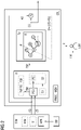
- figure 2 illustrates a machine control CTL according to the invention in a training phase.
- the purpose of the training is to enable the machine control CTL to control a machine M—as described above—in an optimized manner.
- the machine control CTL is thus configured by the training.
- the machine control CTL includes one or more processors PROC for executing the method according to the invention and one or more memory modules MEM for storing method data.
- the machine control CTL is coupled to a simulator SIM for simulating the production robot M or one or more of its components.
- the purpose of the simulator SIM is to simulate a large number of status signals ZS and associated optimized control signals AS of the production robot M as training data for training the machine control CTL.
- the status signals ZS each specify one or more statuses of the production robot M, preferably over time.
- the state signals ZS can be represented as numerical data vectors in a first state space S1 mapped by the simulation.
- the optimized control signals can be represented as data vectors in a control action space mapped by the simulation.
- the simulation is intended to determine, in particular for a state of the production robot M specified by a respective state signal ZS, that control signal which optimizes a behavior of the production robot M induced by the control signal according to a predetermined criterion.
- This control signal is then assigned to the relevant status signal ZS as an optimized control signal AS.
- the simulator SIM simulates a behavior of the production robot M for a large number of operating scenarios.
- the latter can include a large number of operating conditions and/or operating states which can occur when the production robot M is in operation.
- Such operating scenarios can in particular be extracted from operating data of the production robot M and/or from a database DB.
- a large number of operating scenarios and operating states of the production robot M are generated by a generator GEN of the simulator SIM.
- the generator GEN preferably generates status signals, trajectories, time series, external influences, operating events and/or secondary conditions that may occur during operation of the production robot M. To vary the generated operating scenarios, they can also be generated randomly.
- the generation of the operating scenarios is based on framework data or model data for the production robot M, which are stored in the database DB and are fed into the generator GEN for the purpose of generation.
- the simulator SIM has a simulation model MM of the production robot M for simulating the behavior of the production robot M in a respectively generated operating scenario.
- a large number of efficient methods are available for the efficient physical simulation of a machine, here M, using a simulation model, here MM, such as so-called finite element methods or multi-body simulation methods.
- the simulator SIM simulates a behavior of the production robot M resulting from the application of a respective control action for a large number of possible states of the production robot M and for a large number of possible control actions Performance evaluated and determined that control signal AS that optimizes this performance.
- the performance-optimizing Control signal AS is then assigned to the relevant status signal ZS.
- the status signals ZS are fed into the machine control CTL with their respective associated, optimized control signal AS as training data from the simulator SIM.
- the status signals ZS and the optimized control signals AS can also be fed into the machine control CTL by the production robot M itself, by a production robot similar thereto, or by a database.
- the machine control CTL is trained using the training data ZS and AS.
- Training is generally understood to mean an optimization of a mapping from input signals to output signals. This mapping is optimized according to predetermined and/or learned criteria during a training phase.
- a prediction error or reproduction error in the case of prediction models, a classification error in the case of classification models, a deviation from an optimized control action in the case of control models and/or minimization of an information loss in the case of conversion models can be used as criteria here.
- model parameters, method parameters, network structures of neurons in a neural network and/or weights of connections between the neurons can be set or optimized in such a way that the criteria are met as well as possible.
- the training can thus be regarded as an optimization problem.
- a large number of efficient optimization methods are available for such optimization problems.
- genetic optimization methods, gradient descent methods, principal component analysis methods and/or particle swarm optimizations can be used.
- the machine control CTL has a first signal converter T1 and a second signal converter T2, which are to be trained using the training data ZS and AS.
- the first signal converter T1 is trained to determine a transformation matrix TM which maps a respective status signal ZS from the first status space S1 into a second status space S2 with reduced dimensions, onto a reduced status signal ZSR. Any loss of information should be minimized.
- the second state space S2 has a considerably smaller dimension than the first state space S1.
- a respective status signal ZS is mapped onto the associated reduced status signal ZSR by matrix multiplication of a vector representing the respective status signal ZS in the first status space S1 with the transformation matrix TM.
- the result of this multiplication is then a vector representing the associated reduced state signal ZSR in the second state space S2.
- ZSR TM*ZS, with the representing vectors being denoted by the same reference symbols as the state signals ZS or ZSR shown, to simplify the notation.
- the matrix elements of the transformation matrix TM and possibly their number of rows are optimized in such a way that a loss of information occurring during the transformation is minimized. This can be done, for example, by determining a loss of information for a large number of transformations for variations in the matrix elements and in this way determining a set of matrix elements which minimizes the loss of information. As a measure of the loss of information, it can be determined, for example, how well the original status signals ZS can be reproduced from reduced status signals ZSR.
- the transformation matrix TM is determined by a main component analysis PCA. A large number of standard numerical methods, for example for singular value decomposition, are available for carrying out such a principal component analysis.
- the status signals ZS and the associated optimized control signals AS are fed to the first signal converter T1.
- the main component analysis PCA is advantageously carried out jointly for the status signals ZS and the control signals AS.
- the transformation matrix TM is extended by additional columns for multiplication with a vector representing a control signal.
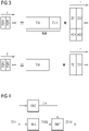
- FIG. 3 A conversion of status signals ZS and optionally associated optimized control signals AS by the transformation matrix TM or an extended transformation matrix TME is illustrated in FIG.
- the upper part of figure 3 illustrates a conversion by means of a transformation matrix TME expanded by additional columns TMA, as is used for the principal component analysis PCA.
- ZS1, ZS2, ... each illustrate a vector representing a status signal and AS1, AS2, ... each represent a vector representing a control signal over time T.
- the vectors ZS1, ZS2 , ... in each case supplemented by an associated vector AS1 or AS2, ... to form an extended vector which now represents a status signal and its associated control signal together.
- the expanded vectors (ZS1, AS2), (ZS2, AS2), . . . are each multiplied by the expanded transformation matrix TME in order to obtain a reduced state vector ZSR1 or ZSR2, .
- the principal component analysis PCA is performed for the extended transformation matrix TME.
- the extended columns TMA are then removed again, so that only the transformation matrix TM remains.
- the resulting transformation matrix TM is then used for multiplication with non-expanded state vectors ZS1, ZS2, . . . in order to convert from the first state space S1 to the reduced, second state space S2 as intended.
- This implementation by the transformation matrix TM is shown in the lower part of figure 3 illustrated.
- status signals ZS are mapped onto their main components PC found by the main component analysis PCA.
- the main components PC to a certain extent span the second state space S2.
- the joint main component analysis PCA of status signals ZS with their associated optimized control signals AS is advantageous in that it also allows correlations between status signals ZS and control signals AS to be recognized and used for efficient dimension reduction.
- the reduced status signals ZSR obtained by converting the status signals ZS using the transformation matrix TM are transmitted from the first signal converter T1 to a second signal converter T2 of the machine control CTL. If an optimized control signal AS is assigned to a respective status signal ZS, the latter is also assigned to the reduced control signal ZSR converted from this status signal ZS.
- the second signal converter T2 is to be trained to convert reduced status signals into optimized control signals by means of an explicit conversion rule R.
- a large number of reduced status signals ZSR are each converted in accordance with the conversion rule R, and a resulting output signal OS of the second signal converter T2 is compared with the respectively associated optimized control signal AS.
- the conversion rule R is then optimized or parameterized so that a distance D between the output signals OS and the respective associated optimized control signals AS is minimized.
- the conversion rule R is composed of discrete control elements, which in the present exemplary embodiment include, in particular, numeric operators.
- numeric operators For example, addition, subtraction, multiplication, division, exponentiation, a sine function and/or a cosine function can be used as numerical operators.
- the operators are each encoded by a specific operator identifier, preferably a common operator symbol. In figure 2 some example operators are marked by the operator symbols +, * and EXP. The operators act on operands A, B and C.
- the conversion rule R comprises one or more sequences of numeric operators, which are preferably structured as a so-called expression tree or algorithmic tree.
- Such an expression tree is formed by a tree-like linked data structure made up of coded operators, operands and, if necessary, numeric parameters. In the linking direction, the operators act on operands or on the results of linked operations.
- An expression tree encodes a symbolic mathematical expression or an explicit symbolic formula. In particular, an expression tree with multiple operands can be viewed as a multivariate function.
- the conversion of the second signal converter T2 is defined by the expression tree of the conversion rule R.
- the conversion rule R thus forms a generally non-linear multivariate function which is evaluated numerically by the second signal converter T2.
- a symbolic regression is carried out for the expression tree.
- the latter is varied with the aim of finding a conversion rule R which converts a reduced status signal ZSR into control signals which are as advantageous as possible.
- a large number of different sequences of operators and operands are generated.
- the output signals OS generated by applying the sequence to the reduced status signals ZSR are compared with the optimized control signal AS assigned to a respective reduced status signal ZSR.
- or D (OS - AS) 2 .
- the distance D becomes - as in figure 2 indicated by a dotted arrow - to the second signal converter T2, in order to select or optimize an operator sequence there, which minimizes the distance D.
- a genetic optimization method is preferably used for minimization. A large number of efficient implementations are available for such genetic optimization methods.
- the second signal converter T2 is trained to reproduce the optimized control signals AS as precisely as possible. In many cases the optimized control signals AS can be reproduced with an accuracy of 1% or less. After successful training, the output signals OS of the second signal converter T2 can thus be output as optimized control signals and used for the optimized control of the production robot M.
- the series connection of the first signal converter T1 and the second signal converter T2 forms a so-called machine learning pipeline.
- the first signal converter T1 and the second signal converter T2 and thus the machine control CTL are trained and configured by the training.
- the two signal converters T1 and T2 can preferably be trained together.
- the transformation matrix TM optimized by the training and the conversion rule R optimized by the training can advantageously be output by the first signal converter T1 or by the second signal converter T2 to a user USR of the machine control CTL.
- Both the transformation matrix TM and the conversion rule R can be easily interpreted by the user USR due to their explicit representation.
- the conversion rule R forms an explicit heuristic control rule that is analytically comprehensible, certifiable and further developable. This represents a significant advantage over data-driven models such as neural networks, whose transformations are usually difficult to understand analytically.
- a plurality of operating condition-specific second signal converters T2 can be provided, which are specifically trained for a respective operating condition. As soon as a current operating condition for the production robot M is then detected or recorded, a second signal converter T2 specifically trained for this current operating condition can be selected.
- the training of the second signal converter T2 can often be improved by additionally generating a large number of synthetic reduced state signals and used for training.
- Such a generation of synthetic reduced state signals ZSRS is figure 4 illustrated.
- a machine learning module NN for example a neural network, is trained using a large number of reduced state signals ZSR to generate synthetic reduced state signals ZSRG, which are as similar as possible to the reduced state signals ZSR according to specified criteria and/or have a similar statistical distribution .
- the machine learning module NM can be stimulated in particular by random signals. A large number of known methods are available for training such a machine learning module NM.
- the reduced state data ZSR used to train the machine learning module NN are additionally fed into an extractor CHE, which determines and extracts a convex envelope CH of the reduced state data in the second state space.
- the synthetic reduced state signals ZSRG generated by the machine learning module NN and the convex envelope CH are fed into a sampling device SMP.
- the synthetic reduced state signals ZSRG are sampled by the sampling device SMP by interpolation within the complex envelope CH on a preferably equidistant grid of the state space S2.
- the sampled synthetic reduced status signals ZSRS are then output by the sampling device SMP and used as additional reduced status signals for training the second signal converter T2.
Landscapes
- Engineering & Computer Science (AREA)
- Artificial Intelligence (AREA)
- Health & Medical Sciences (AREA)
- Computer Vision & Pattern Recognition (AREA)
- Evolutionary Computation (AREA)
- Medical Informatics (AREA)
- Software Systems (AREA)
- Physics & Mathematics (AREA)
- General Physics & Mathematics (AREA)
- Automation & Control Theory (AREA)
- Feedback Control In General (AREA)
Priority Applications (5)
| Application Number | Priority Date | Filing Date | Title |
|---|---|---|---|
| EP21166569.0A EP4068011A1 (fr) | 2021-04-01 | 2021-04-01 | Commande de machine, ainsi que procédé de configuration de la commande de machine |
| PCT/EP2022/057081 WO2022207353A1 (fr) | 2021-04-01 | 2022-03-17 | Dispositif de commande de machine et procédé de configuration du dispositif de commande de machine |
| US18/552,514 US20240176310A1 (en) | 2021-04-01 | 2022-03-17 | Machine controller and method for configuring the machine controller |
| CN202280026020.9A CN117157592A (zh) | 2021-04-01 | 2022-03-17 | 机器控制器以及用于配置机器控制器的方法 |
| EP22716064.5A EP4295199A1 (fr) | 2021-04-01 | 2022-03-17 | Dispositif de commande de machine et procédé de configuration du dispositif de commande de machine |
Applications Claiming Priority (1)
| Application Number | Priority Date | Filing Date | Title |
|---|---|---|---|
| EP21166569.0A EP4068011A1 (fr) | 2021-04-01 | 2021-04-01 | Commande de machine, ainsi que procédé de configuration de la commande de machine |
Publications (1)
| Publication Number | Publication Date |
|---|---|
| EP4068011A1 true EP4068011A1 (fr) | 2022-10-05 |
Family
ID=75362418
Family Applications (2)
| Application Number | Title | Priority Date | Filing Date |
|---|---|---|---|
| EP21166569.0A Withdrawn EP4068011A1 (fr) | 2021-04-01 | 2021-04-01 | Commande de machine, ainsi que procédé de configuration de la commande de machine |
| EP22716064.5A Pending EP4295199A1 (fr) | 2021-04-01 | 2022-03-17 | Dispositif de commande de machine et procédé de configuration du dispositif de commande de machine |
Family Applications After (1)
| Application Number | Title | Priority Date | Filing Date |
|---|---|---|---|
| EP22716064.5A Pending EP4295199A1 (fr) | 2021-04-01 | 2022-03-17 | Dispositif de commande de machine et procédé de configuration du dispositif de commande de machine |
Country Status (4)
| Country | Link |
|---|---|
| US (1) | US20240176310A1 (fr) |
| EP (2) | EP4068011A1 (fr) |
| CN (1) | CN117157592A (fr) |
| WO (1) | WO2022207353A1 (fr) |
Citations (2)
| Publication number | Priority date | Publication date | Assignee | Title |
|---|---|---|---|---|
| EP3291029A1 (fr) * | 2016-08-29 | 2018-03-07 | Siemens Aktiengesellschaft | Procédé et dispositif de commande d'un système technique à l'aide d'un modèle de commande |
| EP3588211A1 (fr) * | 2018-06-27 | 2020-01-01 | Siemens Aktiengesellschaft | Dispositif de commande destiné à la commande d'un système technique et procédé de configuration du dispositif de commande |
Family Cites Families (9)
| Publication number | Priority date | Publication date | Assignee | Title |
|---|---|---|---|---|
| DE102007001025B4 (de) * | 2007-01-02 | 2008-11-20 | Siemens Ag | Verfahren zur rechnergestützten Steuerung und/oder Regelung eines technischen Systems |
| DE102010011221B4 (de) * | 2010-03-12 | 2013-11-14 | Siemens Aktiengesellschaft | Verfahren zur rechnergestützten Steuerung und/oder Regelung eines technischen Systems |
| JP5550970B2 (ja) * | 2010-04-12 | 2014-07-16 | 住友重機械工業株式会社 | 画像生成装置及び操作支援システム |
| US10754334B2 (en) * | 2016-05-09 | 2020-08-25 | Strong Force Iot Portfolio 2016, Llc | Methods and systems for industrial internet of things data collection for process adjustment in an upstream oil and gas environment |
| US11204597B2 (en) * | 2016-05-20 | 2021-12-21 | Moog Inc. | Outer space digital logistics system |
| DE102016224207A1 (de) * | 2016-12-06 | 2018-06-07 | Siemens Aktiengesellschaft | Verfahren und Steuereinrichtung zum Steuern eines technischen Systems |
| US10783248B2 (en) * | 2017-01-18 | 2020-09-22 | New York University | Determining an aspect of behavior of an embedded device such as, for example, detecting unauthorized modifications of the code and/or behavior of an embedded device |
| US10725475B2 (en) * | 2018-04-09 | 2020-07-28 | Toyota Jidosha Kabushiki Kaisha | Machine learning enhanced vehicle merging |
| US10983524B2 (en) * | 2018-04-12 | 2021-04-20 | Baidu Usa Llc | Sensor aggregation framework for autonomous driving vehicles |
-
2021
- 2021-04-01 EP EP21166569.0A patent/EP4068011A1/fr not_active Withdrawn
-
2022
- 2022-03-17 CN CN202280026020.9A patent/CN117157592A/zh active Pending
- 2022-03-17 EP EP22716064.5A patent/EP4295199A1/fr active Pending
- 2022-03-17 WO PCT/EP2022/057081 patent/WO2022207353A1/fr not_active Ceased
- 2022-03-17 US US18/552,514 patent/US20240176310A1/en active Pending
Patent Citations (2)
| Publication number | Priority date | Publication date | Assignee | Title |
|---|---|---|---|---|
| EP3291029A1 (fr) * | 2016-08-29 | 2018-03-07 | Siemens Aktiengesellschaft | Procédé et dispositif de commande d'un système technique à l'aide d'un modèle de commande |
| EP3588211A1 (fr) * | 2018-06-27 | 2020-01-01 | Siemens Aktiengesellschaft | Dispositif de commande destiné à la commande d'un système technique et procédé de configuration du dispositif de commande |
Non-Patent Citations (1)
Also Published As
| Publication number | Publication date |
|---|---|
| US20240176310A1 (en) | 2024-05-30 |
| CN117157592A (zh) | 2023-12-01 |
| EP4295199A1 (fr) | 2023-12-27 |
| WO2022207353A1 (fr) | 2022-10-06 |
Similar Documents
| Publication | Publication Date | Title |
|---|---|---|
| EP2649567B1 (fr) | Procédée pour la modélisation sur ordinateur d'un système technique | |
| EP3914979B1 (fr) | Capteur virtuel sur une plateforme pour machines supérieures | |
| EP3451202B1 (fr) | Procédé de génération d'un modèle d'un système technique exécutable sur un appareil d'essai et appareil d'essai | |
| EP3629151A1 (fr) | Procédé de changement de modèles pour la génération du code source | |
| EP2718774A1 (fr) | Système de simulation, procédé permettant d'effectuer une simulation, système de guidage et produit de programme informatique | |
| WO2012098170A1 (fr) | Modèle de simulation d'une éolienne et production et utilisation dudit modèle | |
| EP4235317A1 (fr) | Procédé de commande d'une machine par un agent de commande basé sur l'apprentissage, ainsi que dispositif de commande | |
| EP4375768B1 (fr) | Procédé et commande de machine pour commander une machine | |
| WO2019057489A1 (fr) | Procédé et générateur de données d'entraînement destinés à configurer un système technique et équipement de commande destiné à commander le système technique (ts) | |
| EP4174720B1 (fr) | Procédé et dispositif de commande d'un système technique | |
| EP4068011A1 (fr) | Commande de machine, ainsi que procédé de configuration de la commande de machine | |
| DE102023134540A1 (de) | Verfahren und System zur automatisierten Spezifikation von Testfällen zum Testen von Softwarefunktionen eines Steuergerätes | |
| EP4036663B1 (fr) | Dispositif de commande permettant de commander un système technique et procédé de configuration du dispositif de commande | |
| EP3705960A1 (fr) | Procédé d'interprétation automatique d'un schéma de tuyauterie | |
| EP4273636A1 (fr) | Procédé et dispositif de commande permettant de commander une machine | |
| EP4050430A1 (fr) | Dispositif de commande permettant de commander un système technique et procédé de configuration du dispositif de commande | |
| DE102011076969B4 (de) | Verfahren zum rechnergestützten Lernen einer Regelung und/oder Steuerung eines technischen Systems | |
| EP0704778B1 (fr) | Procédé de distribution d'énergie dans des installations et dispositif pour sa mise en oeuvre | |
| EP4016202A1 (fr) | Procédé de reproduction des composantes de bruit des signaux de fonctionnement enregistrés avec pertes et dispositif de commande | |
| EP4686984A1 (fr) | Procédé et commande de machine pour commander une machine | |
| DE102019123892A1 (de) | Verfahren und Vorrichtung zur Simulation von Ereignissen eines technischen Systems | |
| DE102019216676A1 (de) | Prognose eines Messwerts einer Messgröße eines technischen Systems | |
| WO2023012180A1 (fr) | Procédé et système pour commander un système de production | |
| EP3989012A1 (fr) | Procédé et système de configuration destinés à la configuration d'un dispositif de commande pour un système technique | |
| DE10013509C1 (de) | Verfahren zur datenbasierten Konstruktion eines Moduls mit den Daten entsprechendem Übertragungsverhalten und Modul hierfür |
Legal Events
| Date | Code | Title | Description |
|---|---|---|---|
| PUAI | Public reference made under article 153(3) epc to a published international application that has entered the european phase |
Free format text: ORIGINAL CODE: 0009012 |
|
| STAA | Information on the status of an ep patent application or granted ep patent |
Free format text: STATUS: THE APPLICATION HAS BEEN PUBLISHED |
|
| AK | Designated contracting states |
Kind code of ref document: A1 Designated state(s): AL AT BE BG CH CY CZ DE DK EE ES FI FR GB GR HR HU IE IS IT LI LT LU LV MC MK MT NL NO PL PT RO RS SE SI SK SM TR |
|
| STAA | Information on the status of an ep patent application or granted ep patent |
Free format text: STATUS: THE APPLICATION IS DEEMED TO BE WITHDRAWN |
|
| 18D | Application deemed to be withdrawn |
Effective date: 20230406 |