EP4070905B1 - Électrode de soudage par résistance électrique - Google Patents
Électrode de soudage par résistance électrique Download PDFInfo
- Publication number
- EP4070905B1 EP4070905B1 EP21760444.6A EP21760444A EP4070905B1 EP 4070905 B1 EP4070905 B1 EP 4070905B1 EP 21760444 A EP21760444 A EP 21760444A EP 4070905 B1 EP4070905 B1 EP 4070905B1
- Authority
- EP
- European Patent Office
- Prior art keywords
- sliding member
- guide pin
- thin
- guide hole
- extended portion
- Prior art date
- Legal status (The legal status is an assumption and is not a legal conclusion. Google has not performed a legal analysis and makes no representation as to the accuracy of the status listed.)
- Active
Links
Images


Classifications
-
- B—PERFORMING OPERATIONS; TRANSPORTING
- B23—MACHINE TOOLS; METAL-WORKING NOT OTHERWISE PROVIDED FOR
- B23K—SOLDERING OR UNSOLDERING; WELDING; CLADDING OR PLATING BY SOLDERING OR WELDING; CUTTING BY APPLYING HEAT LOCALLY, e.g. FLAME CUTTING; WORKING BY LASER BEAM
- B23K11/00—Resistance welding; Severing by resistance heating
- B23K11/30—Features relating to electrodes
- B23K11/3009—Pressure electrodes
- B23K11/3018—Cooled pressure electrodes
-
- B—PERFORMING OPERATIONS; TRANSPORTING
- B23—MACHINE TOOLS; METAL-WORKING NOT OTHERWISE PROVIDED FOR
- B23K—SOLDERING OR UNSOLDERING; WELDING; CLADDING OR PLATING BY SOLDERING OR WELDING; CUTTING BY APPLYING HEAT LOCALLY, e.g. FLAME CUTTING; WORKING BY LASER BEAM
- B23K11/00—Resistance welding; Severing by resistance heating
- B23K11/14—Projection welding
-
- B—PERFORMING OPERATIONS; TRANSPORTING
- B29—WORKING OF PLASTICS; WORKING OF SUBSTANCES IN A PLASTIC STATE IN GENERAL
- B29C—SHAPING OR JOINING OF PLASTICS; SHAPING OF MATERIAL IN A PLASTIC STATE, NOT OTHERWISE PROVIDED FOR; AFTER-TREATMENT OF THE SHAPED PRODUCTS, e.g. REPAIRING
- B29C45/00—Injection moulding, i.e. forcing the required volume of moulding material through a nozzle into a closed mould; Apparatus therefor
- B29C45/14—Injection moulding, i.e. forcing the required volume of moulding material through a nozzle into a closed mould; Apparatus therefor incorporating preformed parts or layers, e.g. injection moulding around inserts or for coating articles
-
- B—PERFORMING OPERATIONS; TRANSPORTING
- B29—WORKING OF PLASTICS; WORKING OF SUBSTANCES IN A PLASTIC STATE IN GENERAL
- B29C—SHAPING OR JOINING OF PLASTICS; SHAPING OF MATERIAL IN A PLASTIC STATE, NOT OTHERWISE PROVIDED FOR; AFTER-TREATMENT OF THE SHAPED PRODUCTS, e.g. REPAIRING
- B29C45/00—Injection moulding, i.e. forcing the required volume of moulding material through a nozzle into a closed mould; Apparatus therefor
- B29C45/0001—Injection moulding, i.e. forcing the required volume of moulding material through a nozzle into a closed mould; Apparatus therefor characterised by the choice of material
-
- B—PERFORMING OPERATIONS; TRANSPORTING
- B29—WORKING OF PLASTICS; WORKING OF SUBSTANCES IN A PLASTIC STATE IN GENERAL
- B29C—SHAPING OR JOINING OF PLASTICS; SHAPING OF MATERIAL IN A PLASTIC STATE, NOT OTHERWISE PROVIDED FOR; AFTER-TREATMENT OF THE SHAPED PRODUCTS, e.g. REPAIRING
- B29C45/00—Injection moulding, i.e. forcing the required volume of moulding material through a nozzle into a closed mould; Apparatus therefor
- B29C45/14—Injection moulding, i.e. forcing the required volume of moulding material through a nozzle into a closed mould; Apparatus therefor incorporating preformed parts or layers, e.g. injection moulding around inserts or for coating articles
- B29C45/14336—Coating a portion of the article, e.g. the edge of the article
- B29C45/14426—Coating the end of wire-like or rod-like or cable-like or blade-like or belt-like articles
-
- B—PERFORMING OPERATIONS; TRANSPORTING
- B29—WORKING OF PLASTICS; WORKING OF SUBSTANCES IN A PLASTIC STATE IN GENERAL
- B29K—INDEXING SCHEME ASSOCIATED WITH SUBCLASSES B29B, B29C OR B29D, RELATING TO MOULDING MATERIALS OR TO MATERIALS FOR MOULDS, REINFORCEMENTS, FILLERS OR PREFORMED PARTS, e.g. INSERTS
- B29K2081/00—Use of polymers having sulfur, with or without nitrogen, oxygen or carbon only, in the main chain, as moulding material
- B29K2081/04—Polysulfides, e.g. PPS, i.e. polyphenylene sulfide or derivatives thereof
Definitions
- the present invention relates to an electrical resistance welding electrode in which a member obtained by integrating a guide pin made of a heat-resistant hard material such as a metal material or a ceramic material and a sliding member made of an insulating synthetic resin material is slidably incorporated in an electrode main body, see the preamble of claim 1 (see for example JP 2019 217548 A ).
- the guide pin and the sliding member are integrated by so-called insert molding in which a synthetic resin material is injected into a mold and the guide pin is subjected to enveloped casting.
- insert molding the wall thickness of the synthetic resin in an inserted portion is set to be thick in order to maintain the coupling rigidity between the guide pin and the sliding member at a predetermined value.
- the thickness as described above is uniformly maintained over the entire length of the sliding member.
- the amount of expansion increases so that the sliding member is strongly pressed over the entire length thereof against the inner face of a guide hole of the electrode main body.
- the sliding wear amount increases. Thereafter, when the sliding member returns to ordinary temperature or the temperature of the sliding member decreases due to a decrease in the number of times of welding, the gap between the sliding member and the guide hole becomes excessive.
- the guide pin exists on the center side, and therefore force in the diameter direction in the inserted portion during thermal expansion strongly acts on the inner face of the guide hole. Furthermore, since the expansion of the guide pin itself is added, the pressing force acting on the inner face of the guide hole increases. Further, the inserted portion receives heat also from the guide pin.
- the extended portion has a cylindrical shape, and the inside thereof is a space.
- the heat insulating portion that is formed at a boundary portion between the inserted portion and the extended portion and with which the end face of the guide pin is in close contact is disposed, the amount of heat transferred to the extended portion is smaller than the amount of heat transferred to the inserted portion.
- the thickness of the extended portion as viewed in the diameter direction of the guide pin is molded to be thinner than the thickness of the inserted portion.
- a flat portion for an air passage is provided in the sliding member, and a thin-wall deformable portion is formed in the extended portion. Therefore, when the extended portion is heated, the expansion force in the circumferential direction of the non-thin-wall deformable portion in which the thin-wall deformable portion is not formed acts from both sides of the thin-wall deformable portion, and the surface of the thin-wall deformable portion bulges toward the inside of the air passage.
- the pressing force acting on the inner face of the guide hole in the extended portion during thermal expansion is smaller than the pressing force acting on the inner face of the guide hole in the inserted portion during thermal expansion. Therefore, the sliding wear amount in the extended portion is significantly smaller than the sliding wear amount in the inserted portion.
- the wear amount in the extended portion is very small, or substantially zero. Even if the sliding member contracts resulting from returning of the sliding member to ordinary temperature due to operation shutdown or from lowering of the temperature due to reduction of the number of times of welding, the gap between the inserted portion and the guide hole is large, but the gap between the extended portion and the guide hole is very small or substantially absent.
- the amount of thermal expansion and contraction of the inserted portion appears large.
- the synthetic resin material bites into the finely projected and recessed portion, the integrity of the guide pin and the synthetic resin material in the inserted portion can be reliably maintained.
- the present invention is the invention of the welding electrode as described above.
- the electrode main body will be described.
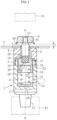
- An electrode main body 1 made of a copper alloy has a cylindrical shape, and a fixed portion 2 to be inserted into a stationary member 11 and a cap 4 on which a steel plate part 3 is placed are joined together at a threaded portion 5.
- a central axial line of the electrode main body 1 is denoted by reference sign O-O.
- a guide hole 6 having a circular section is formed in the electrode main body 1.
- a tapered portion 12 is formed below the fixed portion 2, and the tapered portion 12 is fitted into a tapered hole provided in the stationary member 11.
- a vent hole 13 for introducing compressed air for cooling into the guide hole 6 is provided in the side portion of the fixed portion 2.
- the electrode main body 1 is a fixed electrode, and a movable electrode corresponding thereto is denoted by reference numeral 24.
- the guide pin 16 is made of a heat-resistant hard material such as a metal material, e.g., stainless steel, or a ceramic material.
- the sliding member 15 is made of an insulating synthetic resin having excellent heat resistance, for example, a polyphenylene sulfide (PPS) resin suitable for injection molding.
- PPS polyphenylene sulfide
- the guide pin 16 and the sliding member 15 both have a circular section.
- the guide pin 16 passes through a through hole 8 provided in the cap 4 and a pilot hole 7 of the steel plate part 3 to perform a positioning function of the steel plate part 3, and supports a projection nut 9 made of iron and fitted to the front-end portion of the guide pin 16. Therefore, a minor diameter portion 10 that matches the screw hole of the projection nut 9 is formed.
- the projection nut may be simply referred to as a nut.
- This embodiment employs the latter, i.e., plastic deformation, and specifically, knurling. Fine projections and recesses are formed on the surface of the rotary mold, and pressed against the surface of the guide pin 16 to rotate, whereby a projection-and-recess shape can be obtained due to plastic deformation. As illustrated in FIG. 5 and other drawings, this projection-and-recess shape is formed on the surface of the guide pin 16 in a state where grooves parallel in the inclined direction and other grooves parallel in the inclined direction are crossed each other, and has a rough feel when touched by hand. When the injection molding is completed, as illustrated in FIG. 4 , the synthetic resin spreads all over the projections and the recesses of the projection-and-recess portion to integrate the guide pin 16 and the sliding member 15.
- the projected and recessed portion 14 is exposed to the mold cavity, whereby the projected and recessed portion 14 is inserted with the synthetic resin.
- the sliding member 15 is slidably fitted into the guide hole 6 with substantially no gap.
- An air passage 22 is formed in order to circulate the cooling air having entered from the vent hole 13 along the sliding member 15.
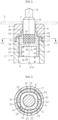
- the air passage 22 is formed in the central axial line O-O direction by forming a flat portion 23 on the outer peripheral face of the sliding member 15. A mold shape corresponding to the flat portion 23 is defined, and the flat portion 23 is obtained by die molding at the time of injection molding.
- the air passages 22 are formed at four positions of the sliding member 15, cylindrical faces 32 are retained at four positions other than the air passages 22, and slide on the inner face of the guide hole 6 with substantially no gap.
- the sliding member 15 performs an insulating function such that, when the movable electrode 24 advances and a welding current is applied, the current flows only from a welding projection 46 of the nut 9 to the steel plate part 3.
- a void 26 is formed between the through hole 8 and the guide pin 16 to form an air passage for cooling air.
- the guide pin 16 is integrated with the sliding member 15 in a state of being inserted into the sliding member 15, passes through the through hole 8 and the pilot hole 7, protrudes beyond the steel plate part 3, and holds the nut 9 at the protruding portion.
- a compression coil spring 27 is fitted between the sliding member 15 and an inner bottom face of the guide hole 6, and tension thereof acts on the sliding member 15.
- An opening 28, having a circular shape, for receiving the compression coil spring 27 is formed below the sliding member 15.
- Reference numeral 29 denotes an insulation sheet fitted into the inner bottom face of the guide hole 6.
- the air pressure introduced from the vent hole 13 can also be used.
- An on-off valve structure portion 43 performs flowing of the cooling air introduced from the vent hole 13 to the void 26 or blocking of the flow to the void 26, that is, performs an on-off valve function.
- an end face 45 of the sliding member 15 comes into close contact with an inner end face 44 of the guide hole 6 to block the cooling air flow, or the end face 45 is separated from the inner end face 44 to flow the cooling air.
- the both faces 44 and 45 exist on an imaginary plane with which the central axial line O-O perpendicularly intersects.
- the upper end face of the sliding member 15 constitutes the close contact face (the end face 45) on the sliding member 15 side, and the close contact face exists on the imaginary plane with which the central axial line O-O perpendicularly intersects as described above.
- the on-off valve structure portion 43 is opened to form a void for air circulation.
- the welding projection 46 is pressed against the steel plate part 3, and a welding current is applied.
- a shape in which the surface of the thin-wall deformable portion 30 bulges and protrudes is indicated by an expansion line 34 depicted by a two-dot chain line.
- the gentle and substantially cylindrical expansion indicated by the expansion line 34 is continuous in the central axial line O-O direction.
- the flat portion 23 is deformed into the shape as indicated by the expansion line 34.
- the force pressing the extended portion 18 against the inner face of the guide hole 6 by the thermal expansion is converted or distributed due to the bulging deformation of the thin-wall deformable portion 30 toward the air passage 22, and thus is significantly smaller than that of the inserted portion 17.
- the inserted portion 17 has a wall thickness larger than that of the extended portion 18, the period of pressing the inner face of the guide hole 6 is prolonged, the progress of the sliding wear continues for a long period of time, and the wear amount of the inserted portion 17 is much larger than that of the extended portion 18.
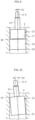
- the temperature of the sliding member 15 returns to ordinary temperature due to stopping of the welding operation or the number of times of welding decreases, the sliding member 15 contracts due to temperature decreases. Further, as illustrated in FIG. 9 , the diameter of the inserted portion 17 becomes smaller than the diameter of the extended portion 18.
- FIG. 9 illustrates a state of external shapes of the inserted portion 17 and the extended portion 18 at the time when the sliding member 15 contracts due to shifting to ordinary temperature caused by stopping the operation or due to temperature reduction caused by a decrease in the number of times of welding.
- the gap between the extended portion 18 and the inner face of the guide hole 6 is substantially zero, and the extended portion 18 slides on the inner face of the guide hole 6 with no gap. Therefore, an inclination angle ⁇ 1 of the guide pin 16 with respect to the central axial line O-O is very small.
- the one-side lower end of the extended portion 18 is in point contact with the inner face of the guide hole 6 at a contact point 39, and the other-side upper end of the extended portion 18 is in point contact with the inner face of the guide hole 6 at a contact point 40.
- the thickness of the sliding member 15 is uniformly maintained over the entire length of the sliding member 15.
- the amount of expansion of the sliding member 15 increases, so that the sliding member 15 is strongly pressed against over the entire length of the inner face of the guide hole 6 of the electrode main body 1.
- the sliding wear amount increases. Thereafter, when the sliding member 15 returns to ordinary temperature or the temperature of the sliding member decreases due to a decrease in the number of times of welding, the gap between the sliding member 15 and the guide hole 6 becomes excessive.
- Reference numeral 41 denotes a lower contact point with respect to the inner face of the guide hole 6, and reference numeral 42 denotes an upper contact point with respect to the inner face of the guide hole 6.
- This inclination angle is denoted by ⁇ 2 in FIG. 10 . Therefore, the guide pin 16 strongly comes into contact with the pilot hole 7 of the steel plate part 3, and a large deviation occurs in the relative position between the steel plate part 3 and the electrode main body 1, which is disadvantageous for improving the welding accuracy.
- the guide pin 16 adapts to a projection bolt 47.
- the projection bolt 47 includes a stem 48 which is externally threaded, a flange 49 that has a circular shape and is integrally formed with the stem 48, and a welding projection 50 which is formed on a lower face of the flange 49.
- the guide pin 16 has a hollow pin shape in which a receiving hole 51 is formed in order to insert the stem 48.
- the projection bolt may be simply referred to as a bolt.
- Other configurations are identical to those in the previous case including portions not illustrated, and members having similar functions are denoted by the same reference numerals.
- the thermal expansion, sliding wear, and the like of the sliding member 15 are also identical to those in the previous case.
- Melting heat generated during welding of the nut 9 or the bolt 47 to the steel plate part 3 by electrical resistance welding is transferred from the steel plate part 3 to the sliding member 15 through the electrode main body 1. At the same time, this melting heat is transferred from the guide pin 16 to the sliding member 15.
- the heat transfer state to the sliding member 15 extends from the inserted portion 17 into which the guide pin 16 is inserted to the extended portion 18 that has a cylindrical shape and is continuous with the inserted portion 17. In the temperature distribution viewed in the central axial line O-O direction of the electrode, the temperature is higher in the inserted portion 17 than in the extended portion 18 because the inserted portion 17 is close to the molten portion.
- the difference in temperature between at the time of use of the electrode and at the time of non-use of the electrode increases in the inserted portion 17, and the amount of expansion or contraction of the inserted portion 17 also increases.
- the wear amount of the inserted portion 17 in such an environment is large.
- the extended portion 18 has a cylindrical shape, and the inside thereof is a space.
- the heat insulating portion 20 that is formed at a boundary portion between the inserted portion 17 and the extended portion 18 and with which the end face 19 of the guide pin 16 is in close contact, the amount of heat transferred to the extended portion 18 is smaller than the amount of heat transferred to the inserted portion 17.
- the thickness T2 of the extended portion 18 as viewed in the diameter direction of the guide pin 16 is molded to be thinner than the thickness T1 of the inserted portion 17.
- the flat portion 23 for the air passage 22 is provided in the sliding member 15, and the thin-wall deformable portion 30 thinner than the extended portion 18 is formed. Therefore, when the extended portion 18 is heated, the expansion force in the circumferential direction of the non-thin-wall deformable portion 31 in which the thin-wall deformable portion 30 is not formed acts from both sides of the thin-wall deformable portion 30, and the surface 23 of the thin-wall deformable portion 30 bulges toward the inside of the air passage 22.
- the pressing force acting on the inner face of the guide hole 6 in the extended portion 18 during thermal expansion is smaller than the pressing force acting on the inner face of the guide hole 6 in the inserted portion 17 during thermal expansion. Therefore, the sliding wear amount in the extended portion 18 is significantly smaller than the sliding wear amount in the inserted portion 17.
- force 35 acting in the diameter direction in the non-thin-wall deformable portion 31 acts on the inner face of the guide hole 6.
- Such a force component 35 is converted into an expansion force in the circumferential direction of the non-thin-wall deformable portion 31.
- the expansion force in the circumferential direction of the non-thin-wall deformable portion 31 acts from both sides of the thin-wall deformable portion 30, whereby the surface 23 of the thin-wall deformable portion 30 deforms in the state where the surface of the thin-wall deformable portion bulges toward the space of the air passage 22.
- the force 35 pressing the extended portion 18 against the inner face of the guide hole 6 by the thermal expansion is distributed due to the bulging deformation of the thin-wall deformable portion 30 toward the air passage 22, and thus is significantly smaller than that of the inserted portion 17.
- the amount of thermal expansion and contraction of the inserted portion 17 appears large.
- the synthetic resin material bites into the finely projected and recessed portion 14, the integrity of the guide pin 16 and the synthetic resin material in the inserted portion 17 can be reliably maintained.
- an inclination angle of the guide pin is reduced by forming a thin portion in the sliding member to reduce a wear amount of the thin portion. Therefore, an electrical resistance welding electrode having good operation reliability can be obtained regardless of thermal expansion, and the electrical resistance welding electrode can be used in a wide industrial field such as welding processes of automotive vehicle body and of sheet metal of household electrical appliances.
Landscapes
- Engineering & Computer Science (AREA)
- Mechanical Engineering (AREA)
- Manufacturing & Machinery (AREA)
- Moulds For Moulding Plastics Or The Like (AREA)
- Injection Moulding Of Plastics Or The Like (AREA)
- Connection Of Plates (AREA)
Claims (1)
- Électrode de soudage par résistance électrique comprenant :un corps principal comprenant un trou de guidage (6) ;un capuchon (4) avec un trou traversant (8) sur lequel une pièce de plaque d'acier (3) peut être placée ;le corps principal (1) et le capuchon (4) étant reliés par une portion filetée (5) ;une broche de guidage (16) ayant une section circulaire, ressortant d'une face d'extrémité d'un corps principal (1) de l'électrode de soudage par résistance électrique, et configurée pour traverser le trou traversant (8) et un trou pilote (7) de la pièce de plaque d'acier (3), la broche de guidage (16) étant constituée d'un matériau dur résistant à la chaleur tel qu'un matériau métallique ou un matériau céramique ;un élément coulissant (15) présentant une section circulaire et monté de manière coulissante dans le trou de guidage (6) du corps principal (1), l'élément coulissant (15) étant constitué d'un matériau en résine synthétique isolante, dans laquellela broche de guidage (16) et l'élément coulissant (15) sont intégrés mutuellement via un surmoulage pendant le moulage par injection de l'élément coulissant (15),l'élément coulissant (15) comprend une portion insérée (17) dans laquelle la broche de guidage (16) est surmoulée, une portion étendue (18) qui présente une forme cylindrique et est positionnée sur un côté inférieur de la portion insérée (17), et une portion d'isolation thermique (20) qui est formée sur une portion de délimitation entre la portion insérée (17) et la portion étendue (18), dans laquelle une position d'une face d'extrémité inférieure (19) de la broche de guidage (16) définit une extrémité inférieure de la portion insérée (17), l'épaisseur (T2) de la portion étendue (18) vue en direction diamétrale de la broche de guidage (16) est inférieure à l'épaisseur (T1) de la portion insérée (17),un passage d'air (22) d'air de refroidissement qui s'écoule dans le trou de guidage (6) à partir d'un évent (13) du corps principal (1) de l'électrode de soudage par résistance électrique est configuré en formant une portion plane (23) sur une face périphérique externe de l'élément coulissant (15),une portion déformable à paroi mince (30) est formée dans la portion étendue (18) en formant le passage d'air (22) de l'air de refroidissement, dans laquelleune quantité d'usure par glissement dans la portion étendue (18) inférieure à une quantité d'usure par glissement dans la portion insérée (17) est assurée par une configuration telle que, quand la portion étendue (18) est chauffée, une surface de la portion déformable à paroi mince (30) se renfle vers l'intérieur du passage d'air (22) en raison d'une force d'expansion (33) en direction circonférentielle d'une portion déformable à paroi non mince (31) dans laquelle la portion déformable à paroi mince (30) n'est pas formée, agissant sur les deux côtés de la portion déformable à paroi mince (30), définissant ainsi une force de pression (35) sur une face interne du trou de guidage (6) dans la portion étendue (18) pendant la dilatation thermique pour qu'elle soit inférieure à une force de pression sur la face interne du trou de guidage (6) dans la portion insérée (17) pendant la dilatation thermique,caractériséeen ce qu'une portion finement saillante et renfoncée (14) est formée sur une surface de la broche de guidage (16) à insérer dans la portion insérée (17) de l'élément coulissant (15), de telle sorte que la broche de guidage (16) est intégrée à l'élément coulissant (15) par le surmoulage,et en ce que l'électrode de soudage par résistance électrique est construite de telle sorte que, lors de l'utilisation, dans un état où l'élément coulissant (15) est à une position limite supérieure, une extrémité supérieure du trou de guidage (6) est positionnée au-dessus de l'extrémité inférieure de la portion insérée (17), de telle sorte que, pendant la dilatation thermique, la portion insérée (17) est toujours montée de manière coulissante sur la face interne du trou de guidage (6).
Applications Claiming Priority (2)
| Application Number | Priority Date | Filing Date | Title |
|---|---|---|---|
| JP2020044730A JP6751519B1 (ja) | 2020-02-25 | 2020-02-25 | 電気抵抗溶接電極 |
| PCT/JP2021/002508 WO2021171864A1 (fr) | 2020-02-25 | 2021-01-25 | Électrode de soudage par résistance électrique |
Publications (3)
| Publication Number | Publication Date |
|---|---|
| EP4070905A1 EP4070905A1 (fr) | 2022-10-12 |
| EP4070905A4 EP4070905A4 (fr) | 2024-01-10 |
| EP4070905B1 true EP4070905B1 (fr) | 2025-03-05 |
Family
ID=72333419
Family Applications (1)
| Application Number | Title | Priority Date | Filing Date |
|---|---|---|---|
| EP21760444.6A Active EP4070905B1 (fr) | 2020-02-25 | 2021-01-25 | Électrode de soudage par résistance électrique |
Country Status (5)
| Country | Link |
|---|---|
| US (1) | US12370619B2 (fr) |
| EP (1) | EP4070905B1 (fr) |
| JP (1) | JP6751519B1 (fr) |
| CN (1) | CN115210028B (fr) |
| WO (1) | WO2021171864A1 (fr) |
Family Cites Families (8)
| Publication number | Priority date | Publication date | Assignee | Title |
|---|---|---|---|---|
| EP1323488B1 (fr) * | 1996-05-11 | 2005-07-20 | Yoshitaka Aoyama | Electrode de soudage |
| JP5967443B2 (ja) | 2013-09-05 | 2016-08-10 | 青山 省司 | 電気抵抗溶接用電極 |
| JP6541029B2 (ja) * | 2015-06-23 | 2019-07-10 | 青山 省司 | 電気抵抗溶接用電極 |
| JP6548116B2 (ja) * | 2015-07-29 | 2019-07-24 | 青山 省司 | 電気抵抗溶接用電極 |
| JP6720458B2 (ja) | 2016-06-02 | 2020-07-08 | 青山 省司 | 電気抵抗溶接電極におけるガイド部材 |
| JP6553004B2 (ja) * | 2016-08-08 | 2019-07-31 | 青山 省司 | 電気抵抗溶接用電極 |
| JP7017715B2 (ja) | 2018-06-14 | 2022-02-09 | 省司 青山 | 電気抵抗溶接電極用ガイドピン |
| JP6493848B1 (ja) * | 2018-07-18 | 2019-04-03 | 青山 省司 | 電気抵抗溶接電極の冷却空気断続方法 |
-
2020
- 2020-02-25 JP JP2020044730A patent/JP6751519B1/ja active Active
-
2021
- 2021-01-25 US US17/791,112 patent/US12370619B2/en active Active
- 2021-01-25 EP EP21760444.6A patent/EP4070905B1/fr active Active
- 2021-01-25 WO PCT/JP2021/002508 patent/WO2021171864A1/fr not_active Ceased
- 2021-01-25 CN CN202180016168.XA patent/CN115210028B/zh active Active
Also Published As
| Publication number | Publication date |
|---|---|
| CN115210028B (zh) | 2024-05-24 |
| JP6751519B1 (ja) | 2020-09-09 |
| EP4070905A1 (fr) | 2022-10-12 |
| EP4070905A4 (fr) | 2024-01-10 |
| CA3164398A1 (fr) | 2021-09-02 |
| US12370619B2 (en) | 2025-07-29 |
| CN115210028A (zh) | 2022-10-18 |
| WO2021171864A1 (fr) | 2021-09-02 |
| US20230035745A1 (en) | 2023-02-02 |
| JP2021133423A (ja) | 2021-09-13 |
Similar Documents
| Publication | Publication Date | Title |
|---|---|---|
| JP6541029B2 (ja) | 電気抵抗溶接用電極 | |
| AU723029B2 (en) | Electrode for welding | |
| KR101948372B1 (ko) | 볼 조인트 및 그 제조 방법 | |
| US10632562B2 (en) | Electrode for electric resistance welding | |
| JPH0911279A (ja) | 射出成形用ノズル | |
| KR20130133296A (ko) | 부시 장치 및 통수 기구와 그 제조 방법 | |
| US12370619B2 (en) | Electrical resistance welding electrode | |
| CA3164398C (fr) | Electrode de soudage par resistance electrique | |
| US7781707B2 (en) | Heated nozzle unit for the moulding of plastics materials | |
| JP6624365B2 (ja) | 電気抵抗溶接電極におけるガイドピンの冷却方法 | |
| JP5967443B2 (ja) | 電気抵抗溶接用電極 | |
| US20180290361A1 (en) | Insert for Use in an Injection Molding Nozzle and Injection Molding Nozzle with Such an Insert | |
| JP6720458B2 (ja) | 電気抵抗溶接電極におけるガイド部材 | |
| JP2000351054A (ja) | ダイカスト用スリーブ | |
| JP6548116B2 (ja) | 電気抵抗溶接用電極 | |
| JP5967444B2 (ja) | 電気抵抗溶接電極用ガイドピンの製造方法 | |
| JP2017136639A (ja) | 電気抵抗溶接用電極 | |
| JP2023027731A (ja) | 電気抵抗溶接用電極 | |
| JP2023016653A (ja) | 電気抵抗溶接用電極 | |
| JPH065130Y2 (ja) | 成形用金型 | |
| US20040084808A1 (en) | Flow pin for injection molding | |
| JP2023069974A (ja) | 電気抵抗溶接用電極 | |
| JP2019042798A (ja) | 電気抵抗溶接用電極 | |
| JPH05212521A (ja) | 鋳造型 | |
| JPH0524148U (ja) | 熱間金型のマンドレル |
Legal Events
| Date | Code | Title | Description |
|---|---|---|---|
| STAA | Information on the status of an ep patent application or granted ep patent |
Free format text: STATUS: THE INTERNATIONAL PUBLICATION HAS BEEN MADE |
|
| PUAI | Public reference made under article 153(3) epc to a published international application that has entered the european phase |
Free format text: ORIGINAL CODE: 0009012 |
|
| STAA | Information on the status of an ep patent application or granted ep patent |
Free format text: STATUS: REQUEST FOR EXAMINATION WAS MADE |
|
| 17P | Request for examination filed |
Effective date: 20220708 |
|
| AK | Designated contracting states |
Kind code of ref document: A1 Designated state(s): AL AT BE BG CH CY CZ DE DK EE ES FI FR GB GR HR HU IE IS IT LI LT LU LV MC MK MT NL NO PL PT RO RS SE SI SK SM TR |
|
| DAV | Request for validation of the european patent (deleted) | ||
| DAX | Request for extension of the european patent (deleted) | ||
| A4 | Supplementary search report drawn up and despatched |
Effective date: 20231207 |
|
| RIC1 | Information provided on ipc code assigned before grant |
Ipc: B29K 81/00 20060101ALI20231201BHEP Ipc: B29C 45/00 20060101ALI20231201BHEP Ipc: B29C 45/14 20060101ALI20231201BHEP Ipc: B23K 11/30 20060101AFI20231201BHEP |
|
| REG | Reference to a national code |
Ref country code: DE Ref legal event code: R079 Free format text: PREVIOUS MAIN CLASS: B23K0011300000 Ipc: B23K0011140000 Ref country code: DE Ref legal event code: R079 Ref document number: 602021027201 Country of ref document: DE Free format text: PREVIOUS MAIN CLASS: B23K0011300000 Ipc: B23K0011140000 |
|
| GRAP | Despatch of communication of intention to grant a patent |
Free format text: ORIGINAL CODE: EPIDOSNIGR1 |
|
| STAA | Information on the status of an ep patent application or granted ep patent |
Free format text: STATUS: GRANT OF PATENT IS INTENDED |
|
| RIC1 | Information provided on ipc code assigned before grant |
Ipc: B29K 81/00 20060101ALI20240912BHEP Ipc: B29C 45/14 20060101ALI20240912BHEP Ipc: B29C 45/00 20060101ALI20240912BHEP Ipc: B23K 11/30 20060101ALI20240912BHEP Ipc: B23K 11/14 20060101AFI20240912BHEP |
|
| INTG | Intention to grant announced |
Effective date: 20240926 |
|
| GRAS | Grant fee paid |
Free format text: ORIGINAL CODE: EPIDOSNIGR3 |
|
| GRAA | (expected) grant |
Free format text: ORIGINAL CODE: 0009210 |
|
| STAA | Information on the status of an ep patent application or granted ep patent |
Free format text: STATUS: THE PATENT HAS BEEN GRANTED |
|
| AK | Designated contracting states |
Kind code of ref document: B1 Designated state(s): AL AT BE BG CH CY CZ DE DK EE ES FI FR GB GR HR HU IE IS IT LI LT LU LV MC MK MT NL NO PL PT RO RS SE SI SK SM TR |
|
| REG | Reference to a national code |
Ref country code: GB Ref legal event code: FG4D |
|
| REG | Reference to a national code |
Ref country code: CH Ref legal event code: EP |
|
| REG | Reference to a national code |
Ref country code: DE Ref legal event code: R096 Ref document number: 602021027201 Country of ref document: DE |
|
| REG | Reference to a national code |
Ref country code: IE Ref legal event code: FG4D |
|
| PG25 | Lapsed in a contracting state [announced via postgrant information from national office to epo] |
Ref country code: RS Free format text: LAPSE BECAUSE OF FAILURE TO SUBMIT A TRANSLATION OF THE DESCRIPTION OR TO PAY THE FEE WITHIN THE PRESCRIBED TIME-LIMIT Effective date: 20250605 |
|
| PG25 | Lapsed in a contracting state [announced via postgrant information from national office to epo] |
Ref country code: FI Free format text: LAPSE BECAUSE OF FAILURE TO SUBMIT A TRANSLATION OF THE DESCRIPTION OR TO PAY THE FEE WITHIN THE PRESCRIBED TIME-LIMIT Effective date: 20250305 |
|
| REG | Reference to a national code |
Ref country code: NL Ref legal event code: MP Effective date: 20250305 |
|
| PG25 | Lapsed in a contracting state [announced via postgrant information from national office to epo] |
Ref country code: ES Free format text: LAPSE BECAUSE OF FAILURE TO SUBMIT A TRANSLATION OF THE DESCRIPTION OR TO PAY THE FEE WITHIN THE PRESCRIBED TIME-LIMIT Effective date: 20250305 |
|
| REG | Reference to a national code |
Ref country code: LT Ref legal event code: MG9D |
|
| PG25 | Lapsed in a contracting state [announced via postgrant information from national office to epo] |
Ref country code: NO Free format text: LAPSE BECAUSE OF FAILURE TO SUBMIT A TRANSLATION OF THE DESCRIPTION OR TO PAY THE FEE WITHIN THE PRESCRIBED TIME-LIMIT Effective date: 20250605 |
|
| PG25 | Lapsed in a contracting state [announced via postgrant information from national office to epo] |
Ref country code: HR Free format text: LAPSE BECAUSE OF FAILURE TO SUBMIT A TRANSLATION OF THE DESCRIPTION OR TO PAY THE FEE WITHIN THE PRESCRIBED TIME-LIMIT Effective date: 20250305 |
|
| PG25 | Lapsed in a contracting state [announced via postgrant information from national office to epo] |
Ref country code: LV Free format text: LAPSE BECAUSE OF FAILURE TO SUBMIT A TRANSLATION OF THE DESCRIPTION OR TO PAY THE FEE WITHIN THE PRESCRIBED TIME-LIMIT Effective date: 20250305 |
|
| PG25 | Lapsed in a contracting state [announced via postgrant information from national office to epo] |
Ref country code: GR Free format text: LAPSE BECAUSE OF FAILURE TO SUBMIT A TRANSLATION OF THE DESCRIPTION OR TO PAY THE FEE WITHIN THE PRESCRIBED TIME-LIMIT Effective date: 20250606 Ref country code: BG Free format text: LAPSE BECAUSE OF FAILURE TO SUBMIT A TRANSLATION OF THE DESCRIPTION OR TO PAY THE FEE WITHIN THE PRESCRIBED TIME-LIMIT Effective date: 20250305 |
|
| REG | Reference to a national code |
Ref country code: AT Ref legal event code: MK05 Ref document number: 1772498 Country of ref document: AT Kind code of ref document: T Effective date: 20250305 |
|
| PG25 | Lapsed in a contracting state [announced via postgrant information from national office to epo] |
Ref country code: NL Free format text: LAPSE BECAUSE OF FAILURE TO SUBMIT A TRANSLATION OF THE DESCRIPTION OR TO PAY THE FEE WITHIN THE PRESCRIBED TIME-LIMIT Effective date: 20250305 |
|
| PG25 | Lapsed in a contracting state [announced via postgrant information from national office to epo] |
Ref country code: SE Free format text: LAPSE BECAUSE OF FAILURE TO SUBMIT A TRANSLATION OF THE DESCRIPTION OR TO PAY THE FEE WITHIN THE PRESCRIBED TIME-LIMIT Effective date: 20250305 |
|
| PG25 | Lapsed in a contracting state [announced via postgrant information from national office to epo] |
Ref country code: SM Free format text: LAPSE BECAUSE OF FAILURE TO SUBMIT A TRANSLATION OF THE DESCRIPTION OR TO PAY THE FEE WITHIN THE PRESCRIBED TIME-LIMIT Effective date: 20250305 |
|
| PG25 | Lapsed in a contracting state [announced via postgrant information from national office to epo] |
Ref country code: PT Free format text: LAPSE BECAUSE OF FAILURE TO SUBMIT A TRANSLATION OF THE DESCRIPTION OR TO PAY THE FEE WITHIN THE PRESCRIBED TIME-LIMIT Effective date: 20250707 |
|
| PG25 | Lapsed in a contracting state [announced via postgrant information from national office to epo] |
Ref country code: PL Free format text: LAPSE BECAUSE OF FAILURE TO SUBMIT A TRANSLATION OF THE DESCRIPTION OR TO PAY THE FEE WITHIN THE PRESCRIBED TIME-LIMIT Effective date: 20250305 Ref country code: IT Free format text: LAPSE BECAUSE OF FAILURE TO SUBMIT A TRANSLATION OF THE DESCRIPTION OR TO PAY THE FEE WITHIN THE PRESCRIBED TIME-LIMIT Effective date: 20250305 |
|
| PG25 | Lapsed in a contracting state [announced via postgrant information from national office to epo] |
Ref country code: AT Free format text: LAPSE BECAUSE OF FAILURE TO SUBMIT A TRANSLATION OF THE DESCRIPTION OR TO PAY THE FEE WITHIN THE PRESCRIBED TIME-LIMIT Effective date: 20250305 |
|
| PG25 | Lapsed in a contracting state [announced via postgrant information from national office to epo] |
Ref country code: EE Free format text: LAPSE BECAUSE OF FAILURE TO SUBMIT A TRANSLATION OF THE DESCRIPTION OR TO PAY THE FEE WITHIN THE PRESCRIBED TIME-LIMIT Effective date: 20250305 |
|
| PG25 | Lapsed in a contracting state [announced via postgrant information from national office to epo] |
Ref country code: RO Free format text: LAPSE BECAUSE OF FAILURE TO SUBMIT A TRANSLATION OF THE DESCRIPTION OR TO PAY THE FEE WITHIN THE PRESCRIBED TIME-LIMIT Effective date: 20250305 |
|
| PG25 | Lapsed in a contracting state [announced via postgrant information from national office to epo] |
Ref country code: SK Free format text: LAPSE BECAUSE OF FAILURE TO SUBMIT A TRANSLATION OF THE DESCRIPTION OR TO PAY THE FEE WITHIN THE PRESCRIBED TIME-LIMIT Effective date: 20250305 |
|
| PG25 | Lapsed in a contracting state [announced via postgrant information from national office to epo] |
Ref country code: IS Free format text: LAPSE BECAUSE OF FAILURE TO SUBMIT A TRANSLATION OF THE DESCRIPTION OR TO PAY THE FEE WITHIN THE PRESCRIBED TIME-LIMIT Effective date: 20250705 |
|
| REG | Reference to a national code |
Ref country code: DE Ref legal event code: R097 Ref document number: 602021027201 Country of ref document: DE |
|
| PLBE | No opposition filed within time limit |
Free format text: ORIGINAL CODE: 0009261 |
|
| STAA | Information on the status of an ep patent application or granted ep patent |
Free format text: STATUS: NO OPPOSITION FILED WITHIN TIME LIMIT |
|
| PG25 | Lapsed in a contracting state [announced via postgrant information from national office to epo] |
Ref country code: DK Free format text: LAPSE BECAUSE OF FAILURE TO SUBMIT A TRANSLATION OF THE DESCRIPTION OR TO PAY THE FEE WITHIN THE PRESCRIBED TIME-LIMIT Effective date: 20250305 |
|
| REG | Reference to a national code |
Ref country code: CH Ref legal event code: L10 Free format text: ST27 STATUS EVENT CODE: U-0-0-L10-L00 (AS PROVIDED BY THE NATIONAL OFFICE) Effective date: 20260114 |
|
| 26N | No opposition filed |
Effective date: 20251208 |
|
| PGFP | Annual fee paid to national office [announced via postgrant information from national office to epo] |
Ref country code: GB Payment date: 20260121 Year of fee payment: 6 |
|
| PGFP | Annual fee paid to national office [announced via postgrant information from national office to epo] |
Ref country code: FR Payment date: 20260123 Year of fee payment: 6 |
|
| PGFP | Annual fee paid to national office [announced via postgrant information from national office to epo] |
Ref country code: CZ Payment date: 20260116 Year of fee payment: 6 |