EP4071313A1 - Élément d'ancrage, système d'ancrage, construction de bâtiment et ouvrage, ainsi que procédé de dissipation d'énergie - Google Patents
Élément d'ancrage, système d'ancrage, construction de bâtiment et ouvrage, ainsi que procédé de dissipation d'énergie Download PDFInfo
- Publication number
- EP4071313A1 EP4071313A1 EP21167641.6A EP21167641A EP4071313A1 EP 4071313 A1 EP4071313 A1 EP 4071313A1 EP 21167641 A EP21167641 A EP 21167641A EP 4071313 A1 EP4071313 A1 EP 4071313A1
- Authority
- EP
- European Patent Office
- Prior art keywords
- anchor
- jacket
- building
- core
- building structure
- Prior art date
- Legal status (The legal status is an assumption and is not a legal conclusion. Google has not performed a legal analysis and makes no representation as to the accuracy of the status listed.)
- Withdrawn
Links
- 238000004873 anchoring Methods 0.000 title claims abstract description 28
- 238000000034 method Methods 0.000 title claims description 7
- 230000021715 photosynthesis, light harvesting Effects 0.000 title claims description 6
- 238000010276 construction Methods 0.000 title description 6
- 239000000463 material Substances 0.000 claims abstract description 53
- 239000002023 wood Substances 0.000 claims description 20
- 230000003313 weakening effect Effects 0.000 claims description 19
- 125000004122 cyclic group Chemical group 0.000 claims description 8
- 239000002184 metal Substances 0.000 claims description 7
- 238000009435 building construction Methods 0.000 claims description 3
- 229910001092 metal group alloy Inorganic materials 0.000 claims description 3
- 238000013461 design Methods 0.000 description 10
- 230000000694 effects Effects 0.000 description 7
- 239000004567 concrete Substances 0.000 description 4
- 230000008859 change Effects 0.000 description 3
- 230000003044 adaptive effect Effects 0.000 description 2
- 230000000295 complement effect Effects 0.000 description 2
- 230000001419 dependent effect Effects 0.000 description 2
- 238000011161 development Methods 0.000 description 2
- 230000001681 protective effect Effects 0.000 description 2
- 230000002829 reductive effect Effects 0.000 description 2
- 239000007787 solid Substances 0.000 description 2
- 230000003068 static effect Effects 0.000 description 2
- 238000012360 testing method Methods 0.000 description 2
- 210000002105 tongue Anatomy 0.000 description 2
- 241000122469 Hypericum hypericoides Species 0.000 description 1
- 230000009471 action Effects 0.000 description 1
- 238000004026 adhesive bonding Methods 0.000 description 1
- 230000003321 amplification Effects 0.000 description 1
- 238000005452 bending Methods 0.000 description 1
- 238000005253 cladding Methods 0.000 description 1
- 238000005553 drilling Methods 0.000 description 1
- 230000005489 elastic deformation Effects 0.000 description 1
- 238000005516 engineering process Methods 0.000 description 1
- 238000009434 installation Methods 0.000 description 1
- 230000003993 interaction Effects 0.000 description 1
- 239000000203 mixture Substances 0.000 description 1
- 238000012544 monitoring process Methods 0.000 description 1
- 238000003199 nucleic acid amplification method Methods 0.000 description 1
- 230000010355 oscillation Effects 0.000 description 1
- 230000002093 peripheral effect Effects 0.000 description 1
- 239000011178 precast concrete Substances 0.000 description 1
- 230000008569 process Effects 0.000 description 1
- 230000009467 reduction Effects 0.000 description 1
- 230000000717 retained effect Effects 0.000 description 1
- 238000005476 soldering Methods 0.000 description 1
- 230000007704 transition Effects 0.000 description 1
- 238000003466 welding Methods 0.000 description 1
Images


Classifications
-
- E—FIXED CONSTRUCTIONS
- E04—BUILDING
- E04B—GENERAL BUILDING CONSTRUCTIONS; WALLS, e.g. PARTITIONS; ROOFS; FLOORS; CEILINGS; INSULATION OR OTHER PROTECTION OF BUILDINGS
- E04B1/00—Constructions in general; Structures which are not restricted either to walls, e.g. partitions, or floors or ceilings or roofs
- E04B1/36—Bearings or like supports allowing movement
-
- E—FIXED CONSTRUCTIONS
- E04—BUILDING
- E04B—GENERAL BUILDING CONSTRUCTIONS; WALLS, e.g. PARTITIONS; ROOFS; FLOORS; CEILINGS; INSULATION OR OTHER PROTECTION OF BUILDINGS
- E04B1/00—Constructions in general; Structures which are not restricted either to walls, e.g. partitions, or floors or ceilings or roofs
- E04B1/18—Structures comprising elongated load-supporting parts, e.g. columns, girders, skeletons
- E04B1/26—Structures comprising elongated load-supporting parts, e.g. columns, girders, skeletons the supporting parts consisting of wood
- E04B1/2604—Connections specially adapted therefor
-
- E—FIXED CONSTRUCTIONS
- E04—BUILDING
- E04H—BUILDINGS OR LIKE STRUCTURES FOR PARTICULAR PURPOSES; SWIMMING OR SPLASH BATHS OR POOLS; MASTS; FENCING; TENTS OR CANOPIES, IN GENERAL
- E04H9/00—Buildings, groups of buildings or shelters adapted to withstand or provide protection against abnormal external influences, e.g. war-like action, earthquake or extreme climate
- E04H9/02—Buildings, groups of buildings or shelters adapted to withstand or provide protection against abnormal external influences, e.g. war-like action, earthquake or extreme climate withstanding earthquake or sinking of ground
- E04H9/021—Bearing, supporting or connecting constructions specially adapted for such buildings
-
- E—FIXED CONSTRUCTIONS
- E04—BUILDING
- E04B—GENERAL BUILDING CONSTRUCTIONS; WALLS, e.g. PARTITIONS; ROOFS; FLOORS; CEILINGS; INSULATION OR OTHER PROTECTION OF BUILDINGS
- E04B1/00—Constructions in general; Structures which are not restricted either to walls, e.g. partitions, or floors or ceilings or roofs
- E04B1/18—Structures comprising elongated load-supporting parts, e.g. columns, girders, skeletons
- E04B1/26—Structures comprising elongated load-supporting parts, e.g. columns, girders, skeletons the supporting parts consisting of wood
- E04B1/2604—Connections specially adapted therefor
- E04B2001/268—Connection to foundations
- E04B2001/2684—Connection to foundations with metal connectors
-
- E—FIXED CONSTRUCTIONS
- E04—BUILDING
- E04B—GENERAL BUILDING CONSTRUCTIONS; WALLS, e.g. PARTITIONS; ROOFS; FLOORS; CEILINGS; INSULATION OR OTHER PROTECTION OF BUILDINGS
- E04B1/00—Constructions in general; Structures which are not restricted either to walls, e.g. partitions, or floors or ceilings or roofs
- E04B1/18—Structures comprising elongated load-supporting parts, e.g. columns, girders, skeletons
- E04B1/26—Structures comprising elongated load-supporting parts, e.g. columns, girders, skeletons the supporting parts consisting of wood
- E04B2001/2696—Shear bracing
Definitions
- the invention relates to an anchor element according to the preamble of claim 1.
- the anchor element is provided for anchoring a (concrete) foundation or a building substructure with a load-bearing building structure for supporting building components.
- the building structure can include wood or a wood material or a wood-like material or made of wood or a wood material or be made of a wood-like material.
- Cross-laminated timber (Cross- Laminated Timber , CLT ), for example, can be used as the wood-based material.
- CLT Cross-laminated timber
- it can also include concrete or be made of concrete, in particular as a precast concrete part, or be made of at least one other material.
- anchoring it is provided that the foundation or subsoil with the building structure arranged or to be arranged on it are mechanically coupled to one another by mechanical connection, in particular clawing.
- the anchor element is formed from a core element and at least one jacket element.
- the invention also relates to an anchoring system according to the preamble of claim 13 and a building structure for supporting building components according to the preamble of claim 15.
- the invention also relates to a building according to the preamble of claim 18 and a method according to the preamble of claim 20.
- energy caused by seismic stresses in a building is dissipated.
- Anchor elements are regularly used in structural engineering when forces and/or moments are to be diverted or transferred from one building component to another building component or to the subsoil. It should be noted that buildings are exposed to various loads. Static-dynamic stress, caused by dead weight, wind load, snow load, etc., must be taken into account on a regular basis. Such loads are usually transferred to rigid anchor elements and in the event of an overload, for example a usage overload, the (rigid) anchor element can fail.
- Structural engineering failure is specifically dependent on seismic stresses on the respective structural seismic behavior (quality), in particular on the load-bearing capacity and the ductility of the components.
- the task is to specify measures with which the ductility of building structures, particularly in the area of the stiffening elements or stiffening walls, is improved so that design restrictions with regard to considering seismic loads in the design become less relevant.
- This object is achieved by an anchor element according to claim 1.
- Further configurations are the subject matter of the secondary and subclaims.
- the jacket element has a higher rigidity than the core element.
- the core element in turn has a higher ductility than the shell element.
- Ductility here means i. W. Plastic deformability within structurally specified parameters, ie without any significant reduction in strength.
- the ductility means that when stresses occur, material failure in the anchor element does not occur immediately, but instead a material change, such as plastic deformation, occurs first.
- the jacket element of the anchor element has a function that stiffens the anchor element.
- the jacket element has at least one material weakness.
- the weakening of the material is preferably arranged at a distance from one end, in particular from both ends, of the anchor element, for example in the middle. Static-dynamic stresses caused by use, dead weight, wind, snow, etc. are transferred to the rigid shell element.
- the rigid shell element of the anchor element fails structurally due to the material weakness located therein, and the stresses acting on the anchor element are transmitted to and dissipated from the ductile core element without structural failure of the anchor element occurring.
- the anchor element and the building structure equipped with it also withstand cyclic seismic loads.
- the bearing capacity of the anchor element (mantle element) and the ductility of the core element are, to a certain extent, adaptively substituted.
- the shell element is preferably stiffer than the core element.
- the stability of the arrangement is based on the one hand on the shell stiffness and on the other hand on the fact that the anchor element is arranged or fixed in the building structure, for example in the wall or support, against lateral buckling. This is all the more so since the stress on the anchor element, particularly in the event of an earthquake, includes (alternating or cyclic) tensile and compressive stresses. Any buckling of the components is critical in the case of compressive stress. By arranging the anchor element in a corresponding bore or recess in the building structure with little or no play, the components do not buckle even under high pressure loads.
- the energy is absorbed by the stiffer casing in the event of a static-dynamic force or energy input.
- the jacket element can be formed as a stiffening element of the armature. If stresses of seismic origin occur, the stiffer shell first fails (breaks) due to the weakening of the material and the energy is absorbed by the ductile, ie plastically deformable, core and dissipated there by plastic deformation, among other things. For example, during an earthquake, which is a situation of high seismic activity, the stable mantle becomes overloaded and buckles or breaks. The ductile core of the arrangement then assumes the anchor function, ie energy is dissipated with or into it without a structural failure of the anchor element occurring. The anchor effect the anchor element arrangement is therefore retained, the structural engineering structure or the building is still securely supported. This is particularly advantageous for wooden structures or wooden buildings.
- Shell element and core element complement each other in the respective, d. H. situational, (carrying) behavior.
- the rigid shell element deforms severely under seismic stress or when it fractures, the ductile core element takes over the energy dissipation.
- the anchor element Before a structural change in the mantle element as a result of large (seismic) forces, the anchor element is comparatively stiff and deforms in the area of elastic deformation, after a structural change in the mantle element (buckling, fracture, tensile failure due to seismic effects), the anchor element becomes ductile and deforms in the area of plastic deformation without the building structure failing or being endangered.
- the anchor element has an adaptive or situational stiffness (stiff in the case of wind or similar, soft in earthquakes - material weakening fails; ductile in earthquakes - core element plasticized). Thanks to the adaptive rigidity, the entire building structure is protected against earthquakes. In the case of strong wind loads or similar, or in the case of light earthquakes, it may happen that the shell element and core element complement one another due to a capacity assessment when protecting the structure. As a result, the structure is stiff against wind or the like, thereby achieving reasonable living comfort. In the event of an earthquake, the supporting structure becomes "soft", which prevents dynamic amplification (resonance) of the acting forces/vibrations.
- the core element and/or the jacket element comprises/comprise at least one metal or is/are formed from at least one metal or at least one metal alloy.
- the core element may be formed from a different material than the shell element.
- the metal of the core element can be less brittle than that of the shell element.
- One suitable ductility can also be achieved through the shapes or geometries of the elements involved.
- the anchor element can have a cylindrical geometry, i. H. a (circular) round cross-section and a longitudinal extension.
- the jacket element encloses the core and can in this respect be formed as a hollow cylinder.
- the core element can also be hollow or hollow-cylindrical.
- the anchor element or the jacket element has a rectangular cross section, resulting in a cuboid geometry, at least with regard to the external dimensions.
- An angular core element or one with a (circular) round cross section can be arranged in the jacket element.
- the weakened material can be arranged in a weakened area of the anchor element.
- the weakened area can be spaced apart from one end of the casing element, in particular from both ends of the casing element.
- the weakened area can be arranged in the middle of the longitudinal extent of the jacket element or in the area of the middle of the anchor element.
- the weakening of the material can be formed by at least one recess in the wall of the casing element, preferably by two opposite recesses.
- the recess forms at least a comparatively thin web in the casing element or a type of tongue which structurally fails when the stresses acting on the anchor element exceed a critical value.
- the web or the webs (tongues) should have a minimum ductility, so that a transition that is as "smooth" as possible (ie as less abrupt as possible) succeeds at the beginning of the (seismic-induced) plasticization. Then the structure of the jacket fails and the ductile (deformable) core takes over the load-bearing or force-absorbing function.
- a development of the area of the cutout on the lateral surface can have an essentially rectangular geometry, in particular with one or more rounded corners.
- the recess can also have an oval geometry or any geometry.
- a plurality of recesses can also be provided, for example with three, four or five or more webs.
- the weakening of the material can extend over the entire circumference of the jacket element.
- the jacket can be thinner in the weakened area, e.g. H. have a thinner wall section.
- a (circumferential) perforation can also be provided in the shell wall to form a material weakening.
- the casing element can be formed in several parts, in particular in two parts, so that it is formed in the longitudinal direction from a first casing element section and at least one second casing element section.
- At least one connecting element which structurally connects the adjacent casing element sections to one another, can be arranged between two adjacent casing element sections.
- the connecting element would preferably be formed so that it is structurally weaker than each of the shell element sections.
- the connecting element can be connected to the casing element or to the casing element sections by welding or soldering or gluing or by another type of connection.
- the fastening means can comprise a screw connection or be formed as a screw connection.
- the anchor element is fastened in a foundation and/or in a structural engineering structure or building component with the fastening means.
- the core element can be longer (on one side or at both ends) than the jacket element, for example so that at least one fastening means can be arranged on the end of the core element.
- the anchor element is mechanically connected to the building structure with the fastening means or means, for example by screwing or other stable connection measures. Provision can be made for at least one fastening counter-means to be provided in the building structure, on or in which the fastening means can be arranged in a stable manner. This also enables the core element to be plasticized "back", ie plastic deformation with an inverted direction.
- a first, in particular inner, jacket element can be arranged adjacent to the core element, and a second, in particular outer, jacket element can in turn be arranged adjacent to the inner jacket element and at a distance from the core element.
- the anchor element can thus comprise three components, an outer, an inner and an intermediate component between the outer and the inner.
- the inner component (core element) can be formed as a solid cylinder.
- the outer component (mantle element) and the intermediate component (intermediate element) can be formed as a hollow cylinder, i. H. as a first hollow cylinder (inner shell element, intermediate element) and as a second hollow cylinder (outer shell element).
- the anchor element comprises other elements (intermediate elements) in addition to a core element and an (outer) jacket element, the energy dissipation in the arrangement can be better tailored to specific application situations.
- the materials or material compositions of the components can differ from one another in such a way that the intermediate element is less stiff (brittle) than the shell element.
- the intermediate element or the (outer) jacket element can have the function of a holding element for at least one other element of the anchor element. It can thus serve as a lateral mount, in particular as a buckling mount.
- This is expedient insofar as the core element is initially plastically deformed under tension in the event of an earthquake, ie it is stretched along the longitudinal axis, as a result of which the core element becomes thinner or slimmer at least in sections. Since the seismic action is cyclically alternating, load reversal takes place and the core element is then replasticized, ie longitudinally compressed. The thinned or slimmed down core element could buckle in the process, which is avoided by a suitable intermediate element or by the buckling mount.
- the arrangement with a buckling mount makes it possible for the core element to be subjected to alternating tensile and compressive loads without it buckling laterally.
- the buckling mount (intermediate element) and/or the jacket element derive the transversal forces, ie forces directed transversely to the longitudinal direction, to the surroundings of the anchor element, ie to the building structure.
- At least one material weakening can also be arranged in the second casing element. If only a material weakening is provided in the anchor element, this is preferably arranged in the outer casing element. Otherwise, any weakening of the material can have the properties already described herein.
- the ductility of building structures is also improved, in particular so that design restrictions with regard to considering seismic stresses in the design become less relevant, by means of an anchoring system according to claim 13.
- the anchoring system is at least one for anchoring Foundation or at least one subsoil with at least one viable building structure for supporting building components. At least two of the anchor elements described herein are arranged in the at least one building structure.
- At least one thrust anchor can be provided which can be connected to the foundation or building subsoil and which is preferably arranged between the anchor elements in or on the building structure.
- the thrust anchor can comprise a (metallic) base plate, which can be connected to the foundation/substructure, for example by screwing, and a (metal) profile, for example a U-profile, which can be arranged in or on the building structure.
- an (anchor) screw connection can be provided, which z. B. in a bore or recess of the building structure is arranged.
- the ductility of building structures is also improved, in particular so that structural restrictions with regard to taking seismic stresses into account in the structure become less relevant, by means of a building structure according to claim 15.
- the building structure is for supporting building components and at least one anchoring element described herein or an anchoring system described herein is provided.
- the anchor element or the anchor elements are arranged, for example, in a suitable (core) hole in the building structure in a buckling-proof manner, resulting in a stable, earthquake-proof association.
- the building structure can comprise wood or a wood material or a wood-like material or be made of wood or a wood material or a wood-like material.
- the material can be formed as cross laminated timber, as CLT, as solid wood or glued laminated timber.
- the building structure can be a (bracing) wall or a column.
- the anchor or the anchoring system can also i. Z. m. a timber frame construction (Timber Frame) can be used.
- the building structure can be used, for example, in the edge supports of wood frame walls or formed as the edge support of a wood frame wall.
- At least one control means for controlling the condition of one or more anchor elements can be provided in the building structure.
- the control means can, for example, comprise an opening through which the anchor element can be viewed, in particular the area of the anchor element in which the material weakening is arranged.
- the monitoring means can be used to monitor whether a controlled failure of the jacket material has taken place in the anchor. If necessary, after checking the condition of the anchor with the control means, whether the structure should be repaired or replaced after the earthquake incident.
- the ductility of building structures is also improved, in particular so that design restrictions with regard to considering seismic stresses in the design are less relevant, by means of a structure, in particular a building, according to claim 18 anchoring system described herein provided and/or a building structure described herein.
- the structure can include wood-based materials or wood-like materials.
- the ductility of building structures is also improved, in particular so that design restrictions with regard to considering seismic stresses in the design become less relevant, using a method according to claim 20.
- energy is caused by cyclic seismic stresses in a structure, in particular in a structure described herein, dissipated.
- At least one anchor element described herein is used, and/or an anchoring system described herein, preferably with at least one structural design described herein. In the event of an earthquake, the energy dissipation occurs through plastic deformation in the core element of the anchor element.
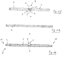
- FIG Figure 1A A perspective view of an anchor element 1 with a core element 2 and a jacket element 3 can be seen in FIG Figure 1A be removed.
- the Figure 1B shows the cylindrical core element 2 and in Figure 1C the casing element 3 is shown.
- the jacket element 3 has a hollow-cylindrical geometry, with the inner diameter of the jacket element 3 essentially corresponding to the outer diameter of the core element 2, so that the core element 2 can be arranged in the jacket element 3 with little or no play, for example by pushing it in.
- the core element 1 arranged in the jacket element 3 forms the anchor element 1 according to FIG Figure 1A .
- the core element 2 has a higher ductility than the jacket element 3 .
- the jacket element 3 is made more rigid than the core element 2 .
- a material weakening 4 of the material of the jacket element 3 is provided in the jacket element 3, approximately in the middle of the anchor element 1, a material weakening 4 of the material of the jacket element 3 is provided.
- the material weakening 4 is according to Figure 3A /D formed as recesses 5 in the wall 6 of the casing element 3. the 3D shows two opposing recesses 5, wherein a web 7 is formed between the recesses 5 in each case.
- Initial (cyclic) tests with an anchor element 1 have shown that the ductility D C of the anchor element 1 is in the range from about 10 to about 20, in particular in the range from about 12 to about 18.
- Tests with a (tested) CLT wall 21 have an effective ductility D C in the range from about 5 to about 10, in particular in the range from about 8 to about 9. These values are comparatively high, so that the constructions (21) with the anchoring technology according to the invention ensure very effective earthquake protection.
- the forces acting on the anchor element 1 that exceed the threshold value are absorbed by the ductile core element 2 and dissipated there if the jacket element 3 fails.
- the high ductility of the core element 2 is achieved in that the core element 2 has a different geometry than the jacket element 3 and/or in that the core element 2 is formed from a different material, for example from a different metal or metal alloy, than the jacket element 3 .
- the core element 2 is formed as a hollow cylinder, so that the anchor element 1 ( Figure 2A ) is hollow inside.
- the anchor element 1 Figure 2A
- the core element 2 is arranged in each case a threaded portion 11, so that the anchor element 1, for example, with a fastener 12, in particular an anchoring system (13, see Figures 7A to 7C ), can be screwed.
- Anchor element 1 shown schematically and in perspective comprises, in addition to a cylindrical core element 2 ( Figure 3B ) and an (outer) hollow-cylindrical casing element 3 ( 3D ) a hollow-cylindrical intermediate element 14 ( Figure 3C ), which is arranged between core element 2 and jacket element 3.
- the core element 2 is arranged in the intermediate element 14 and is fixed there by arranging the fastening means 12 at the ends.
- the intermediate element 14 with the core element 2 arranged therein is arranged in the jacket element 3, which in Figure 3A is shown.
- the anchor element 1 ( Figure 3A ) three components that are arranged inside each other.
- the intermediate element 14 can contribute to the fact that lateral buckling transverse to the longitudinal axis of the elements (2, 3) does not occur, even under tensile/compressive stress.
- the weakening of the material 4 of the casing element 3 is in the Figure 3E shown in detail.
- safety a protective device
- (cyclic) seismic Stresses should be the anchor element 1 ductile.
- the building or the building structure (15) also withstands the forces and resonance effects are avoided.
- the anchor element 1 achieves this by the mantle element 3 structurally failing in a targeted manner, since the seismic forces are above the threshold value, and because the core element 2, which is then subjected to forces, has the required ductility. "Normal" forces/stresses, ie those below the threshold value, are derived from the stiff shell element 3, as a result of which the load-bearing building structure (15) can be dimensioned comparatively small despite its seismic safety. This considerably improves the construction of earthquake-proof (wooden) structures.
- an intermediate element 14 ( Figure 4C ) provided with an external thread 16, so that the intermediate element 14 in an internal thread 17 of the casing element 3 ( Figure 4D ) can be screwed in.
- the components of the core element 2 ( Figure 4B ) and casing element 3 with the intermediate element 14 and the fastening means 12 result in the anchor element 1.
- the Figures 5A /B and 6A/B show variants of the weakened area 9 in jacket elements 3.
- the recess 5 in the weakened area 9 is rectangular (in development).
- the casing element 3 comprises two casing element sections 18, with a peripheral recess 19 being arranged between the casing element sections 18 is.
- the jacket element 3 is in two parts.
- Connecting webs (connecting elements 20) are arranged between the casing element sections 18, for example by means of a welded connection.
- the webs (20) and/or the welded connection form the protective device that fails in a controlled manner in the event of an earthquake, and thus a predetermined breaking point.
- the constructively stiff shell element 3 becomes soft as a result of the controlled failure (fracture) of the webs (20). Resonance effects are reduced (extension of the fundamental oscillation time).
- the anchor element 1 then becomes ductile, and energy is thus dissipated as a result of plastic deformation therein. This means that the fundamental vibration in the building can be extended, energy is dissipated and resonant vibration effects are avoided.
- the building structure (21) or the structure thus withstands the earthquake.
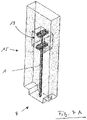
- An anchoring system 13 which includes an anchor element 1 , is arranged in the load-bearing wooden structure 15 of a wooden structure.
- the timber structure may be an edge support, such as a timber frame wall or bracing panel, e.g. B. St. Andrew's crosses or other strut arrangements (diagonal, K-braces, etc.).
- the anchor element 1 can correspond to one of the variants described herein.
- the anchor element 1 is connected to the wooden structure 15 on the one hand and to a (concrete) foundation 8 on the other.
- FIG. 8A shows a perspective view of the wall 21.
- an anchor element 1 is arranged, ie an anchor element 1 on the right side and an anchor element 1 on the left side of the wall 21.
- the anchor (1, 22) can be fastened to the foundation 8 with the fastening means 25 .
- a thrust anchor 22 is arranged between the anchor elements 1, approximately in the middle, and in the area of the lower wall edge.
- the thrust anchor 22 comprises a base plate 23 and a profile 24 arranged in the wall 21.
- the base plate 23 can be fastened to the foundation 8 with fastening means 25.
- the anchor element 1 can be viewed through the bore 26, in particular after an earthquake event. After the earthquake event, it can be evaluated purely visually with little effort as to whether the anchor element 1 or components (3, 7, 9) of the anchor element 1 have changed structurally.
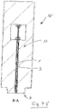
- FIG. 8A A side view of wall 21 according to FIG Figure 8A can he Figure 8B be removed.
- Figure 8C shows a top view of the wall 21 according to FIG Figures 8A /B,
- Figure 8D the face of the wall 21 and
- Figure 8E a sectional view showing the position of the anchor elements (1, 22) and the recesses for it.
Landscapes
- Engineering & Computer Science (AREA)
- Architecture (AREA)
- Civil Engineering (AREA)
- Structural Engineering (AREA)
- Business, Economics & Management (AREA)
- Emergency Management (AREA)
- Environmental & Geological Engineering (AREA)
- Physics & Mathematics (AREA)
- Electromagnetism (AREA)
- Buildings Adapted To Withstand Abnormal External Influences (AREA)
Priority Applications (2)
| Application Number | Priority Date | Filing Date | Title |
|---|---|---|---|
| EP21167641.6A EP4071313A1 (fr) | 2021-04-09 | 2021-04-09 | Élément d'ancrage, système d'ancrage, construction de bâtiment et ouvrage, ainsi que procédé de dissipation d'énergie |
| EP22167389.0A EP4071314A1 (fr) | 2021-04-09 | 2022-04-08 | Élément ancre, système d' ancrage, construction et ouvrage, ainsi que procédé de dissipation d'énergie |
Applications Claiming Priority (1)
| Application Number | Priority Date | Filing Date | Title |
|---|---|---|---|
| EP21167641.6A EP4071313A1 (fr) | 2021-04-09 | 2021-04-09 | Élément d'ancrage, système d'ancrage, construction de bâtiment et ouvrage, ainsi que procédé de dissipation d'énergie |
Publications (1)
| Publication Number | Publication Date |
|---|---|
| EP4071313A1 true EP4071313A1 (fr) | 2022-10-12 |
Family
ID=75477885
Family Applications (2)
| Application Number | Title | Priority Date | Filing Date |
|---|---|---|---|
| EP21167641.6A Withdrawn EP4071313A1 (fr) | 2021-04-09 | 2021-04-09 | Élément d'ancrage, système d'ancrage, construction de bâtiment et ouvrage, ainsi que procédé de dissipation d'énergie |
| EP22167389.0A Pending EP4071314A1 (fr) | 2021-04-09 | 2022-04-08 | Élément ancre, système d' ancrage, construction et ouvrage, ainsi que procédé de dissipation d'énergie |
Family Applications After (1)
| Application Number | Title | Priority Date | Filing Date |
|---|---|---|---|
| EP22167389.0A Pending EP4071314A1 (fr) | 2021-04-09 | 2022-04-08 | Élément ancre, système d' ancrage, construction et ouvrage, ainsi que procédé de dissipation d'énergie |
Country Status (1)
| Country | Link |
|---|---|
| EP (2) | EP4071313A1 (fr) |
Citations (2)
| Publication number | Priority date | Publication date | Assignee | Title |
|---|---|---|---|---|
| WO1982004455A1 (fr) * | 1981-06-19 | 1982-12-23 | Karl S Koller | Entretoise portante a absorption d'energie et procede d'obtention d'une telle entretoise pouvant supporter des charges cycliques superieures a sa resistance au flechissement |
| CN111425037A (zh) * | 2020-03-11 | 2020-07-17 | 同济大学 | 带可更换金属圆棒消能阻尼器的钢结构柱脚 |
-
2021
- 2021-04-09 EP EP21167641.6A patent/EP4071313A1/fr not_active Withdrawn
-
2022
- 2022-04-08 EP EP22167389.0A patent/EP4071314A1/fr active Pending
Patent Citations (2)
| Publication number | Priority date | Publication date | Assignee | Title |
|---|---|---|---|---|
| WO1982004455A1 (fr) * | 1981-06-19 | 1982-12-23 | Karl S Koller | Entretoise portante a absorption d'energie et procede d'obtention d'une telle entretoise pouvant supporter des charges cycliques superieures a sa resistance au flechissement |
| CN111425037A (zh) * | 2020-03-11 | 2020-07-17 | 同济大学 | 带可更换金属圆棒消能阻尼器的钢结构柱脚 |
Also Published As
| Publication number | Publication date |
|---|---|
| EP4071314A1 (fr) | 2022-10-12 |
Similar Documents
| Publication | Publication Date | Title |
|---|---|---|
| EP1797258B1 (fr) | Construction d'appui stabilisée | |
| EP2888419B1 (fr) | Ensemble de support et construction érigée au moyen dudit ensemble de support | |
| EP2698488A2 (fr) | Système de liasion de support | |
| EP1057950B1 (fr) | Dispositif de liaison de deux éléments de construction | |
| EP2725155B1 (fr) | Système pour connecter un premier et un second composants pour former un angle de cadre rigide | |
| DE4110362C2 (de) | Steifigkeitsoptimierte Schraubenverbindung erhöhter Sicherheit gegenüber impulsartiger Zugbelastungen | |
| EP4071313A1 (fr) | Élément d'ancrage, système d'ancrage, construction de bâtiment et ouvrage, ainsi que procédé de dissipation d'énergie | |
| EP1722037A2 (fr) | Dispositif de guidage de la circulation | |
| EP3586614B1 (fr) | Systeme de connection pour meuble modulaire ou stand de foire | |
| EP2898158B1 (fr) | Elément de fixation pour un dispositif de sécurité | |
| JP3293777B2 (ja) | コンクリート棒状構造体の補強器具および補強方法 | |
| DE102019133999A1 (de) | Anordnung zum Verbinden eines Bauwerkteils mit einem dem Bauwerkteil vorgelagerten Außenteil | |
| EP1098043A1 (fr) | Elément de construction pour la connection insonorisée de parties de constructions | |
| EP4397447A1 (fr) | Bati de machine resistant aux vibrations et pourvu de profiles en aluminium | |
| EP2607560B1 (fr) | Élément de raccordement de dalle | |
| EP3161226B1 (fr) | Cheville d'ancrage | |
| DE2732183A1 (de) | Stossverbindung von teilen aus stahlbeton | |
| EP3835501B1 (fr) | Arrangement pour connecter une pièce de construction avec une partie extérieure frontale | |
| EP4339383B1 (fr) | Dispositif de liaison pour la liaison de transmission de force d'une première partie de construction absorbant de force à une seconde partie de construction absorbant de force et construction | |
| DE102023206034A1 (de) | Anordnung und Verfahren zum nachträglichen Verstärken eines Bauteils mit mindestens einem Diskontinuitätsbereich | |
| AT505270A1 (de) | Stahlbeton-stütze | |
| EP2379824B1 (fr) | Ancre de fixation destinée à la fixation d'une façade | |
| EP1589234B1 (fr) | Dispositif de fixation | |
| AT522359B1 (de) | Verbindungsvorrichtung zum kraftschlüssigen Verbinden wenigstens zweier Betonfertigteile | |
| WO2024235955A1 (fr) | Ensemble de raccordement permettant de relier des parties de structure de support d'une structure de support |
Legal Events
| Date | Code | Title | Description |
|---|---|---|---|
| PUAI | Public reference made under article 153(3) epc to a published international application that has entered the european phase |
Free format text: ORIGINAL CODE: 0009012 |
|
| STAA | Information on the status of an ep patent application or granted ep patent |
Free format text: STATUS: THE APPLICATION HAS BEEN PUBLISHED |
|
| AK | Designated contracting states |
Kind code of ref document: A1 Designated state(s): AL AT BE BG CH CY CZ DE DK EE ES FI FR GB GR HR HU IE IS IT LI LT LU LV MC MK MT NL NO PL PT RO RS SE SI SK SM TR |
|
| STAA | Information on the status of an ep patent application or granted ep patent |
Free format text: STATUS: THE APPLICATION IS DEEMED TO BE WITHDRAWN |
|
| 18D | Application deemed to be withdrawn |
Effective date: 20230413 |