EP4072937B1 - Optimierung der radialen verriegelung eines blattzapfens mit einstellbarer neigung für die nabe eines turbomaschinenfans - Google Patents
Optimierung der radialen verriegelung eines blattzapfens mit einstellbarer neigung für die nabe eines turbomaschinenfans Download PDFInfo
- Publication number
- EP4072937B1 EP4072937B1 EP20828037.0A EP20828037A EP4072937B1 EP 4072937 B1 EP4072937 B1 EP 4072937B1 EP 20828037 A EP20828037 A EP 20828037A EP 4072937 B1 EP4072937 B1 EP 4072937B1
- Authority
- EP
- European Patent Office
- Prior art keywords
- stud
- pivot
- ring
- clamping
- clamping parts
- Prior art date
- Legal status (The legal status is an assumption and is not a legal conclusion. Google has not performed a legal analysis and makes no representation as to the accuracy of the status listed.)
- Active
Links
Images


Classifications
-
- F—MECHANICAL ENGINEERING; LIGHTING; HEATING; WEAPONS; BLASTING
- F01—MACHINES OR ENGINES IN GENERAL; ENGINE PLANTS IN GENERAL; STEAM ENGINES
- F01D—NON-POSITIVE DISPLACEMENT MACHINES OR ENGINES, e.g. STEAM TURBINES
- F01D7/00—Rotors with blades adjustable in operation; Control thereof
-
- B—PERFORMING OPERATIONS; TRANSPORTING
- B64—AIRCRAFT; AVIATION; COSMONAUTICS
- B64C—AEROPLANES; HELICOPTERS
- B64C11/00—Propellers, e.g. of ducted type; Features common to propellers and rotors for rotorcraft
- B64C11/02—Hub construction
- B64C11/04—Blade mountings
- B64C11/06—Blade mountings for variable-pitch blades
-
- F—MECHANICAL ENGINEERING; LIGHTING; HEATING; WEAPONS; BLASTING
- F01—MACHINES OR ENGINES IN GENERAL; ENGINE PLANTS IN GENERAL; STEAM ENGINES
- F01D—NON-POSITIVE DISPLACEMENT MACHINES OR ENGINES, e.g. STEAM TURBINES
- F01D25/00—Component parts, details, or accessories, not provided for in, or of interest apart from, other groups
- F01D25/16—Arrangement of bearings; Supporting or mounting bearings in casings
-
- F—MECHANICAL ENGINEERING; LIGHTING; HEATING; WEAPONS; BLASTING
- F16—ENGINEERING ELEMENTS AND UNITS; GENERAL MEASURES FOR PRODUCING AND MAINTAINING EFFECTIVE FUNCTIONING OF MACHINES OR INSTALLATIONS; THERMAL INSULATION IN GENERAL
- F16B—DEVICES FOR FASTENING OR SECURING CONSTRUCTIONAL ELEMENTS OR MACHINE PARTS TOGETHER, e.g. NAILS, BOLTS, CIRCLIPS, CLAMPS, CLIPS OR WEDGES; JOINTS OR JOINTING
- F16B21/00—Means for preventing relative axial movement of a pin, spigot, shaft or the like and a member surrounding it; Stud-and-socket releasable fastenings
- F16B21/10—Means for preventing relative axial movement of a pin, spigot, shaft or the like and a member surrounding it; Stud-and-socket releasable fastenings by separate parts
- F16B21/16—Means for preventing relative axial movement of a pin, spigot, shaft or the like and a member surrounding it; Stud-and-socket releasable fastenings by separate parts with grooves or notches in the pin or shaft
- F16B21/18—Means for preventing relative axial movement of a pin, spigot, shaft or the like and a member surrounding it; Stud-and-socket releasable fastenings by separate parts with grooves or notches in the pin or shaft with circlips or like resilient retaining devices, i.e. resilient in the plane of the ring or the like; Details
- F16B21/186—Means for preventing relative axial movement of a pin, spigot, shaft or the like and a member surrounding it; Stud-and-socket releasable fastenings by separate parts with grooves or notches in the pin or shaft with circlips or like resilient retaining devices, i.e. resilient in the plane of the ring or the like; Details external, i.e. with contracting action
-
- F—MECHANICAL ENGINEERING; LIGHTING; HEATING; WEAPONS; BLASTING
- F16—ENGINEERING ELEMENTS AND UNITS; GENERAL MEASURES FOR PRODUCING AND MAINTAINING EFFECTIVE FUNCTIONING OF MACHINES OR INSTALLATIONS; THERMAL INSULATION IN GENERAL
- F16C—SHAFTS; FLEXIBLE SHAFTS; ELEMENTS OR CRANKSHAFT MECHANISMS; ROTARY BODIES OTHER THAN GEARING ELEMENTS; BEARINGS
- F16C33/00—Parts of bearings; Special methods for making bearings or parts thereof
- F16C33/30—Parts of ball or roller bearings
- F16C33/58—Raceways; Race rings
- F16C33/60—Raceways; Race rings divided or split, e.g. comprising two juxtaposed rings
-
- F—MECHANICAL ENGINEERING; LIGHTING; HEATING; WEAPONS; BLASTING
- F16—ENGINEERING ELEMENTS AND UNITS; GENERAL MEASURES FOR PRODUCING AND MAINTAINING EFFECTIVE FUNCTIONING OF MACHINES OR INSTALLATIONS; THERMAL INSULATION IN GENERAL
- F16C—SHAFTS; FLEXIBLE SHAFTS; ELEMENTS OR CRANKSHAFT MECHANISMS; ROTARY BODIES OTHER THAN GEARING ELEMENTS; BEARINGS
- F16C35/00—Rigid support of bearing units; Housings, e.g. caps, covers
- F16C35/04—Rigid support of bearing units; Housings, e.g. caps, covers in the case of ball or roller bearings
- F16C35/06—Mounting or dismounting of ball or roller bearings; Fixing them onto shaft or in housing
- F16C35/063—Fixing them on the shaft
-
- F—MECHANICAL ENGINEERING; LIGHTING; HEATING; WEAPONS; BLASTING
- F05—INDEXING SCHEMES RELATING TO ENGINES OR PUMPS IN VARIOUS SUBCLASSES OF CLASSES F01-F04
- F05D—INDEXING SCHEME FOR ASPECTS RELATING TO NON-POSITIVE-DISPLACEMENT MACHINES OR ENGINES, GAS-TURBINES OR JET-PROPULSION PLANTS
- F05D2260/00—Function
- F05D2260/30—Retaining components in desired mutual position
-
- F—MECHANICAL ENGINEERING; LIGHTING; HEATING; WEAPONS; BLASTING
- F05—INDEXING SCHEMES RELATING TO ENGINES OR PUMPS IN VARIOUS SUBCLASSES OF CLASSES F01-F04
- F05D—INDEXING SCHEME FOR ASPECTS RELATING TO NON-POSITIVE-DISPLACEMENT MACHINES OR ENGINES, GAS-TURBINES OR JET-PROPULSION PLANTS
- F05D2260/00—Function
- F05D2260/70—Adjusting of angle of incidence or attack of rotating blades
-
- F—MECHANICAL ENGINEERING; LIGHTING; HEATING; WEAPONS; BLASTING
- F16—ENGINEERING ELEMENTS AND UNITS; GENERAL MEASURES FOR PRODUCING AND MAINTAINING EFFECTIVE FUNCTIONING OF MACHINES OR INSTALLATIONS; THERMAL INSULATION IN GENERAL
- F16C—SHAFTS; FLEXIBLE SHAFTS; ELEMENTS OR CRANKSHAFT MECHANISMS; ROTARY BODIES OTHER THAN GEARING ELEMENTS; BEARINGS
- F16C19/00—Bearings with rolling contact, for exclusively rotary movement
- F16C19/02—Bearings with rolling contact, for exclusively rotary movement with bearing balls essentially of the same size in one or more circular rows
- F16C19/04—Bearings with rolling contact, for exclusively rotary movement with bearing balls essentially of the same size in one or more circular rows for radial load mainly
- F16C19/06—Bearings with rolling contact, for exclusively rotary movement with bearing balls essentially of the same size in one or more circular rows for radial load mainly with a single row or balls
Definitions
- the present invention relates to the general field of turbomachines equipped with one or two ducted or non-ducted fan(s), and more particularly to the control of the orientation of the fan blades of these turbomachines.
- a preferred field of application of the invention is that of turbojets comprising a fan with a very high dilution rate (large fan diameter) and a very low pressure ratio.
- the operability of a turbojet with a very high bypass ratio is ensured by introducing variability on the low-pressure module of the turbojet, this variability being activated according to the flight phases to restore a sufficient pumping margin.
- the radial retention of the fan blades is generally ensured by the shape of the blade root and the cell which receives it, by a pivot and its rolling bearings to take up all the forces to which the blade is subjected, by the fan hub in which all the pivots are integrated, and by the fan casing.
- each blade consists of a pivot comprising a bulb-shaped attachment, an external rolling bearing and an internal rolling bearing which make it possible to take up the aerodynamic and inertial forces and centrifugal forces undergone by the blade and its pivot, an eccentric connected by splines to the pivot, and a hub integrating all of the pivots.
- the main aim of the present invention is therefore to propose a blade pivot with adjustable orientation which does not present the aforementioned drawbacks, in particular by eliminating any residual mounting play.
- the pivot according to the invention is remarkable in that it provides radial retention of the stud via “keystone” type tightening.
- the clamping nut When tightening the clamping nut, it will cause the clamping parts to slide radially outwards until they come into contact with the internal ring of the rolling bearing. The clamping parts are then forced to refocus inwards until they come into contact with the retention ring housed in the groove of the stud.
- the invention makes it possible to have a system for retaining the stud relative to the rolling bearing which eliminates the usual mounting clearances.
- the forces notably centrifugal
- the forces always pass through the same path, which prevents any other part from taking on the significant loads due to these forces. This results in perfect support of the stud, both in operation and when stopping the engine, while eliminating any wear on the pivot parts.
- the retention ring comprises a plurality of flat faces which each form a plane/plane contact with a corresponding flat face clamping parts so as to optimize contact between the retention ring and the clamping parts.
- the clamping parts advantageously each comprise a frustoconical face opposite their flat face and coming into conical support with the tightening nut.
- the pivot may include six clamping parts regularly spaced around a radial axis of the pivot.
- the retention ring comprises two distinct ring segments in order to allow its mounting on the stud.
- the pivot further comprises a system for locking the tightening nut on the stud.
- This locking system may include an anti-rotation ring housed in a shoulder of the stud and a snap ring mounted against the anti-rotation ring.
- the invention also relates to a blade with a variable pitch angle for a turbomachine fan hub, comprising an aerodynamic profile and a pivot as defined above.
- the invention also relates to a turbomachine comprising at least one fan hub and at least one set of blades with variable pitch angle as defined above.
- the clamping parts are previously joined together via links made of elastomeric material connecting them to each other, which then makes their assembly easier.
- the invention applies to any turbomachine equipped with at least one ducted or non-ducted fan, and whose fan blades (in the case of a ducted fan) or propeller blades (in the case of a ducted fan) non-ducted blower) are equipped with a pitch adjustment system.
- turbojets of the type comprising a fan with a very high dilution ratio (large fan diameter) and a very low pressure ratio.
- turbojets include a large diameter ducted fan which is provided with a system for changing the pitch of the fan blades.
- Such a pitch timing change system can for example comprise lever arms (or eccentrics) coupled to each blade pivot and pivotally actuated by a jack.
- each blade has the function of ensuring the retention of the fan blade on a rotating fan hub and the guidance of the latter for the timing of its pitch.
- each fan blade is mounted radially in an orifice of the fan hub which it passes right through, the hub being centered on the longitudinal axis of the turbojet.
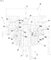
- the pivot 2 of the fan blade according to the invention comprises several distinct elements which are assembled together so as to facilitate its assembly/disassembly from the propeller hub.
- the pivot 2 comprises a stud 4 which extends along the radial axis Z-Z of the pivot through an orifice 6 of the hub 8 of the fan.
- This stud 4 has, at an outer radial end (that is to say at its end furthest from the longitudinal axis of the turbojet), a bulb-shaped attachment 10 which is intended to receive a foot (not shown) of the fan blade.
- a bulb-shaped attachment 10 which is intended to receive a foot (not shown) of the fan blade.
- other means of retaining the root of the blade could be considered.
- the stud 4 At its inner radial end (that is to say at its end closest to the longitudinal axis of the turbojet), the stud 4 comprises an orifice 12 centered on the radial axis Z-Z and intended to receive a timing transmission ring 13 for transmitting the torque to the pivot of the blade to change its pitch.
- the timing transmission ring 13 is coupled to the orifice 12 via splines 15. This timing transmission ring 13 is intended to transmit the torque to the pivot of the blade to change its pitch. It is locked on the stud via a screw 17 centered on the radial axis ZZ and a nut 19 tightened on said screw.
- the pivot according to the invention also comprises a rolling bearing for absorbing the centrifugal forces (that is to say along the radial axis Z-Z) seen by the blade and its pivot.
- the pivot according to the invention comprises an external rolling bearing 14 for absorbing centrifugal forces.
- This rolling bearing is ball bearing. It is provided with an internal ring 16 which is mounted in transverse support against the outer radial end of the stud 4.
- the internal ring 16 is formed of two distinct parts 16a, 16b. This characteristic makes it easier to mount the pivot as will be detailed later.
- the outer rolling bearing 14 also comprises an outer ring 18 which is mounted in transverse support inside the orifice 6 of the hub 8 of the fan, the inner rings 16 and outer rings 18 defining rolling tracks for a plurality of balls 20.
- the pivot can comprise a needle bearing or roller bearing 21 which is offset radially inwards relative to the outer rolling bearing 14.
- the pivot according to the invention also comprises means for radially retaining the stud 4 relative to the block formed by the external rolling bearing 14.
- the stud 4 comprises, at its exterior surface, an annular groove 22 positioned below the internal ring 16 of the exterior rolling bearing 14.
- a retention ring 24 is housed in this groove 22.
- This retention ring is preferably made in two distinct ring segments in order to facilitate its assembly.
- a plurality of clamping parts 26 are each mounted in transverse support against the retention ring 24 and in radial support against the internal ring 16 of the external rolling bearing.
- the clamping parts 26 are for example at number of six and are preferably regularly spaced around the radial axis ZZ.
- the transverse support between the retention ring 24 and the clamping parts 26 is preferably produced by means of “plane/plane” contacts in a direction orthogonal to the radial axis Z-Z.
- the retention ring 24 comprises as many flat faces 24a as there are clamping parts 26, these flat faces 24a being in contact with corresponding flat faces 26a of the clamping parts.
- the radial support between the retention ring 24 and the internal ring 16 of the external rolling bearing is also produced by means of a “plane/plane” contact, this time in the direction of the radial axial Z-Z.
- the radial retention means of the stud also include a tightening nut 28 which is screwed onto an external thread 30 of the stud 4 positioned below the groove 22 receiving the retention ring 24.
- This tightening nut 28 comprises an annular shoulder 28a provided inside with a frustoconical face 28b coming into contact with a corresponding frustoconical face 26b of the clamping parts (the frustoconical face 26b of the clamping parts is opposite their flat face 26a ) to create a conical support.
- the pivot according to the invention further comprises a system for locking the tightening nut 28 on the stud 4.
- this locking system can include an anti-rotation ring 32 which is housed in a shoulder 34 of the stud provided for this purpose.
- the anti-rotation ring 32 is provided with at least one finger 36 which is housed in a notch 28c of the tightening nut 28 to prevent it from pivoting around the radial axis Z-Z.
- a retaining ring 38 (“circlip” type) is mounted radially under the anti-rotation ring to hold the latter in position in the shoulder 34 of the stud.
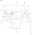
- the outer ring 18 of the outer rolling bearing is mounted in transverse support inside the orifice 6 of the hub 8 of the fan (it is for example shrink-fitted), then the balls 20 of this rolling bearing are mounted.
- the stud 4 is then lowered radially into the orifice 6 of the hub 8, the stud being previously provided with a part 16a of the internal ring of the outer rolling bearing and the retention ring 24.
- the radial stud retention system is assembled. Firstly, the clamping parts 26 are placed opposite the retention ring 24 and the clamping nut 28 is screwed onto the thread 30 of the stud 4 ( 3D figures ).
- FIG 4A more precisely represents an embodiment of these links in elastomeric material 40 when the engine is stopped (free state).
- the links made of elastomer material 40 are crushed towards the inside of the pivot (assembled state - Figure 4B ).
Landscapes
- Engineering & Computer Science (AREA)
- General Engineering & Computer Science (AREA)
- Mechanical Engineering (AREA)
- Aviation & Aerospace Engineering (AREA)
- Structures Of Non-Positive Displacement Pumps (AREA)
Claims (11)
- Drehzapfen (2) für eine Schaufel mit einstellbarer Ausrichtung für die Nabe eines Gebläses einer Turbomaschine, umfassend:einen Klotz (4), der sich entlang einer radialen Achse (Z-Z) erstreckt und an einem radial äußeren Ende Haltemittel (10) für einen Fuß einer Gebläseschaufel und an einem radial inneren Ende Kupplungsmittel für die Übertragung eines Torsionsmoments aufweist,ein Wälzlager (14) zur Aufnahme von Zentrifugalkräften, das einen Innenring (16) aufweist, der quer gegen einen radial äußeren Teil des Klotzes anliegend montiert ist,einen radialen Haltering (24) für den Klotz in Bezug auf das Wälzlager (14), der in einer ringförmigen Nut (22) aufgenommen ist, die in dem Klotz ausgebildet ist,mehrere Klemmstücke (26), die jeweils quer, d. h., in einer Richtung orthogonal zur radialen Achse (Z-Z), gegen den Haltering (24) anliegend und radial, d. h., in Richtung der radialen Achse (Z-Z), gegen den Innenring (16) des Wälzlagers anliegend montiert sind, undeine Klemmmutter (28), die auf ein Außengewinde (30) des Klotzes geschraubt ist, um konisch gegen die Klemmstücke anzuliegen, so dass die Klemmstücke eine Klemmung des Innenrings des Wälzlagers auf dem Klotz und eine Klemmung des Halterings in der Nut sicherstellen.
- Drehzapfen nach Anspruch 1, wobei der Haltering (24) mehrere ebene Seitenflächen (24a) umfasst, die jeweils mit einer entsprechenden ebenen Seitenfläche (26a) der Klemmstücke (26) einen Kontakt von Fläche zu Fläche ausbilden.
- Drehzapfen nach Anspruch 2, wobei die Klemmstücke (26) jeweils eine kegelstumpfförmige Seitenfläche (26b) umfassen, die ihrer ebenen Seitenfläche (26a) gegenüberliegt und konisch gegen die Klemmmutter (28) zur Anlage kommt.
- Drehzapfen nach einem der Ansprüche 1 bis 3, umfassend sechs Klemmstücke (26), die regelmäßig um eine radiale Achse (Z-Z) des Drehzapfens herum beabstandet sind.
- Drehzapfen nach einem der Ansprüche 1 bis 4, wobei der Haltering (24) zwei unterschiedliche Ringsegmente umfasst, um seine Montage auf dem Klotz zu erlauben.
- Drehzapfen nach einem der Ansprüche 1 bis 5, ferner umfassend ein Verriegelungssystem für die Klemmmutter auf dem Klotz.
- Drehzapfen nach Anspruch 6, wobei das Verriegelungssystem einen Verdrehsicherungsring (32) umfasst, der in einer Schulter (34) des Klotzes aufgenommen ist, sowie einen Sprengring (38), der gegen den Verdrehsicherungsring montiert ist.
- Schaufel mit variablem Anstellwinkel für die Nabe eines Gebläses einer Turbomaschine, umfassend ein aerodynamisches Profil und einen Drehzapfen (2) nach einem der Ansprüche 1 bis 7.
- Turbomaschine, umfassend zumindest eine Nabe (8) eines Gebläses und zumindest eine Anordnung von Schaufeln mit variablem Anstellwinkel nach Anspruch 8.
- Verfahren zur Montage eines Drehzapfens nach einem der Ansprüche 1 bis 7, der Reihe nach umfassend:a- das Absenken des Klotzes (4) in eine Nabe (8) eines Gebläses, die vorab mit dem Wälzlager (14) versehen worden ist, wobei der Klotz vorab mit dem Haltering (24) versehen worden ist,b- das Anlegen der Klemmstücke (26) dem Haltering gegenüberliegend,c- das Aufschrauben der Klemmmutter (28) auf das Außengewinde (30) des Klotzes, undd- das Verriegeln der Klemmmutter auf dem Klotz.
- Verfahren nach Anspruch 10, bei dem die Klemmstücke (26) zuvor mittels Verbindungen aus Elastomermaterial (40), die sie miteinander verbinden, fest miteinander verbunden werden.
Applications Claiming Priority (2)
| Application Number | Priority Date | Filing Date | Title |
|---|---|---|---|
| FR1914180A FR3104540B1 (fr) | 2019-12-11 | 2019-12-11 | Perfectionnement au verrouillage radial d’un pivot d’aube à orientation réglable pour moyeu de soufflante de turbomachine |
| PCT/FR2020/052257 WO2021116566A1 (fr) | 2019-12-11 | 2020-12-03 | Perfectionnement au verrouillage radial d'un pivot d'aube à orientation réglable pour moyeu de soufflante de turbomachine |
Publications (2)
| Publication Number | Publication Date |
|---|---|
| EP4072937A1 EP4072937A1 (de) | 2022-10-19 |
| EP4072937B1 true EP4072937B1 (de) | 2023-11-08 |
Family
ID=69811202
Family Applications (1)
| Application Number | Title | Priority Date | Filing Date |
|---|---|---|---|
| EP20828037.0A Active EP4072937B1 (de) | 2019-12-11 | 2020-12-03 | Optimierung der radialen verriegelung eines blattzapfens mit einstellbarer neigung für die nabe eines turbomaschinenfans |
Country Status (5)
| Country | Link |
|---|---|
| US (1) | US12006844B2 (de) |
| EP (1) | EP4072937B1 (de) |
| CN (1) | CN114787033B (de) |
| FR (1) | FR3104540B1 (de) |
| WO (1) | WO2021116566A1 (de) |
Families Citing this family (2)
| Publication number | Priority date | Publication date | Assignee | Title |
|---|---|---|---|---|
| US12320391B2 (en) * | 2022-10-19 | 2025-06-03 | GM Global Technology Operations LLC | External snap ring retainer |
| US12565855B1 (en) | 2025-02-14 | 2026-03-03 | General Electric Company | Gas turbine engine |
Family Cites Families (10)
| Publication number | Priority date | Publication date | Assignee | Title |
|---|---|---|---|---|
| GB546621A (en) * | 1940-12-19 | 1942-07-22 | Leonard Gaskell Fairhurst | Improvements in or relating to variable-pitch airscrews |
| JPS4733331U (de) * | 1971-05-07 | 1972-12-14 | ||
| DE102004060022A1 (de) * | 2004-12-14 | 2006-07-13 | Schaeffler Kg | Propellerblattlagerung, insbesondere für längsaxial verstellbare Propellerblätter von Flugzeugpropellern |
| FR2943313B1 (fr) * | 2009-03-23 | 2011-05-27 | Snecma | Helice non carenee a pales a calage variable pour une turbomachine |
| FR2958621B1 (fr) | 2010-04-09 | 2012-03-23 | Snecma | Helice non carenee pour turbomachine. |
| US20160290228A1 (en) * | 2015-04-06 | 2016-10-06 | General Electric Company | Fan bearings for a turbine engine |
| US10100653B2 (en) * | 2015-10-08 | 2018-10-16 | General Electric Company | Variable pitch fan blade retention system |
| FR3046403B1 (fr) * | 2016-01-05 | 2018-02-09 | Safran Aircraft Engines | Pivot de pale a orientation reglable pour moyeu de soufflante de turbomachine |
| FR3046408B1 (fr) * | 2016-01-05 | 2018-02-09 | Safran Aircraft Engines | Dispositif pour le verrouillage du pas et la mise en drapeau de pales de soufflante a orientation reglable d'une helice de turbomachine |
| US10415405B2 (en) * | 2017-04-21 | 2019-09-17 | United Technologies Corporation | Variable pitch fan blade system |
-
2019
- 2019-12-11 FR FR1914180A patent/FR3104540B1/fr active Active
-
2020
- 2020-12-03 WO PCT/FR2020/052257 patent/WO2021116566A1/fr not_active Ceased
- 2020-12-03 US US17/757,023 patent/US12006844B2/en active Active
- 2020-12-03 EP EP20828037.0A patent/EP4072937B1/de active Active
- 2020-12-03 CN CN202080086383.2A patent/CN114787033B/zh active Active
Also Published As
| Publication number | Publication date |
|---|---|
| US20230013057A1 (en) | 2023-01-19 |
| US12006844B2 (en) | 2024-06-11 |
| CN114787033A (zh) | 2022-07-22 |
| EP4072937A1 (de) | 2022-10-19 |
| FR3104540A1 (fr) | 2021-06-18 |
| WO2021116566A1 (fr) | 2021-06-17 |
| CN114787033B (zh) | 2024-10-29 |
| FR3104540B1 (fr) | 2021-12-17 |
Similar Documents
| Publication | Publication Date | Title |
|---|---|---|
| EP3927617B1 (de) | Platzsparender und verstellbarer schaufelzapfen für turbomaschinen | |
| EP2411270B1 (de) | Düsenloser fan für turbomaschine mit schaufeln mit einstellbarem winkel | |
| EP3400168B1 (de) | Verstellpropeller für turbofan-triebwerke | |
| EP1916431B1 (de) | Lageranordnung einer Drehwelle und mit einer solchen Anordnung ausgestatteter Turboreaktor | |
| EP3610136B1 (de) | Vorrichtung zum zentrieren und drehführen einer turbomaschinenwelle mit mittel zur axialen rückhaltung des aussenringes eines lagers | |
| WO2021170780A1 (fr) | Rotor de soufflante à aubes à calage variable et turbomachine équipée d'un tel rotor | |
| EP4396077B1 (de) | System zur steuerung der blattverstellung eines propellers für ein flugzeugturbinentriebwerk | |
| EP4072937B1 (de) | Optimierung der radialen verriegelung eines blattzapfens mit einstellbarer neigung für die nabe eines turbomaschinenfans | |
| WO2024033590A1 (fr) | Helice pour une turbomachine d'aeronef | |
| EP1491725B1 (de) | Lagervorrichtung für eine verstellbare Schaufel | |
| WO2021214399A1 (fr) | Pivot d'aube à orientation réglable et à intégrité sauvegardée pour moyeu de soufflante de turbomachine | |
| EP0433168B1 (de) | Turbomaschinengehäuse mit verstärkter axialer Verriegelung | |
| FR3123696A1 (fr) | Système de commande du calage angulaire d’une aube d’helice pour une turbomachine d’aeronef | |
| FR3126961A1 (fr) | Helice pour une turbomachine d’aeronef | |
| WO2025262389A1 (fr) | Helice a aubes a calage variable a support d'aubes presentant un demontage aise | |
| FR3157891A1 (fr) | Assemblage pour turbomachine d’aeronef, comprenant un dispositif de secours de couplage mecanique de deux pieces tournantes de l’assemblage | |
| FR3145185A1 (fr) | Dispositif d’arret en rotation pour rotor de turbomachine, rotor et turbomachine associes. | |
| FR3154441A1 (fr) | Dispositif de calage conique pour aube mobile et ensemble le comprenant | |
| WO2025088268A1 (fr) | Ensemble pour une helice de turbomachine d'aeronef | |
| FR3136258A1 (fr) | Ensemble comportant un anneau forme de portions sectorisees pour aubes a calage variable, turbomachine equipee d’un tel ensemble et procede de demontage d’un tel ensemble | |
| WO2026052911A1 (fr) | Ensemble pour rotor de compresseur de turbomachine | |
| FR3145340A1 (fr) | Mécanisme de changement de pas avec dispositif de verrouillage | |
| WO2025247911A1 (fr) | Dispositif de transfert fluidique multivoies à partie centrale comprenant deux corps concentriques solidarisés en rotation par des dents respectives | |
| WO2024209163A1 (fr) | Rotor de soufflante avec actionneur a dispositif de verrouillage | |
| FR3151631A1 (fr) | Ensemble comprenant une aube et un systeme de maintien de l'aube |
Legal Events
| Date | Code | Title | Description |
|---|---|---|---|
| STAA | Information on the status of an ep patent application or granted ep patent |
Free format text: STATUS: UNKNOWN |
|
| STAA | Information on the status of an ep patent application or granted ep patent |
Free format text: STATUS: THE INTERNATIONAL PUBLICATION HAS BEEN MADE |
|
| PUAI | Public reference made under article 153(3) epc to a published international application that has entered the european phase |
Free format text: ORIGINAL CODE: 0009012 |
|
| STAA | Information on the status of an ep patent application or granted ep patent |
Free format text: STATUS: REQUEST FOR EXAMINATION WAS MADE |
|
| 17P | Request for examination filed |
Effective date: 20220701 |
|
| AK | Designated contracting states |
Kind code of ref document: A1 Designated state(s): AL AT BE BG CH CY CZ DE DK EE ES FI FR GB GR HR HU IE IS IT LI LT LU LV MC MK MT NL NO PL PT RO RS SE SI SK SM TR |
|
| DAV | Request for validation of the european patent (deleted) | ||
| DAX | Request for extension of the european patent (deleted) | ||
| GRAP | Despatch of communication of intention to grant a patent |
Free format text: ORIGINAL CODE: EPIDOSNIGR1 |
|
| STAA | Information on the status of an ep patent application or granted ep patent |
Free format text: STATUS: GRANT OF PATENT IS INTENDED |
|
| INTG | Intention to grant announced |
Effective date: 20230725 |
|
| GRAS | Grant fee paid |
Free format text: ORIGINAL CODE: EPIDOSNIGR3 |
|
| GRAA | (expected) grant |
Free format text: ORIGINAL CODE: 0009210 |
|
| STAA | Information on the status of an ep patent application or granted ep patent |
Free format text: STATUS: THE PATENT HAS BEEN GRANTED |
|
| AK | Designated contracting states |
Kind code of ref document: B1 Designated state(s): AL AT BE BG CH CY CZ DE DK EE ES FI FR GB GR HR HU IE IS IT LI LT LU LV MC MK MT NL NO PL PT RO RS SE SI SK SM TR |
|
| REG | Reference to a national code |
Ref country code: GB Ref legal event code: FG4D Free format text: NOT ENGLISH |
|
| REG | Reference to a national code |
Ref country code: CH Ref legal event code: EP |
|
| REG | Reference to a national code |
Ref country code: DE Ref legal event code: R096 Ref document number: 602020020852 Country of ref document: DE |
|
| REG | Reference to a national code |
Ref country code: IE Ref legal event code: FG4D Free format text: LANGUAGE OF EP DOCUMENT: FRENCH |
|
| REG | Reference to a national code |
Ref country code: LT Ref legal event code: MG9D |
|
| REG | Reference to a national code |
Ref country code: NL Ref legal event code: MP Effective date: 20231108 |
|
| PG25 | Lapsed in a contracting state [announced via postgrant information from national office to epo] |
Ref country code: GR Free format text: LAPSE BECAUSE OF FAILURE TO SUBMIT A TRANSLATION OF THE DESCRIPTION OR TO PAY THE FEE WITHIN THE PRESCRIBED TIME-LIMIT Effective date: 20240209 |
|
| PG25 | Lapsed in a contracting state [announced via postgrant information from national office to epo] |
Ref country code: IS Free format text: LAPSE BECAUSE OF FAILURE TO SUBMIT A TRANSLATION OF THE DESCRIPTION OR TO PAY THE FEE WITHIN THE PRESCRIBED TIME-LIMIT Effective date: 20240308 |
|
| PG25 | Lapsed in a contracting state [announced via postgrant information from national office to epo] |
Ref country code: LT Free format text: LAPSE BECAUSE OF FAILURE TO SUBMIT A TRANSLATION OF THE DESCRIPTION OR TO PAY THE FEE WITHIN THE PRESCRIBED TIME-LIMIT Effective date: 20231108 |
|
| REG | Reference to a national code |
Ref country code: AT Ref legal event code: MK05 Ref document number: 1629411 Country of ref document: AT Kind code of ref document: T Effective date: 20231108 |
|
| PG25 | Lapsed in a contracting state [announced via postgrant information from national office to epo] |
Ref country code: NL Free format text: LAPSE BECAUSE OF FAILURE TO SUBMIT A TRANSLATION OF THE DESCRIPTION OR TO PAY THE FEE WITHIN THE PRESCRIBED TIME-LIMIT Effective date: 20231108 |
|
| PG25 | Lapsed in a contracting state [announced via postgrant information from national office to epo] |
Ref country code: AT Free format text: LAPSE BECAUSE OF FAILURE TO SUBMIT A TRANSLATION OF THE DESCRIPTION OR TO PAY THE FEE WITHIN THE PRESCRIBED TIME-LIMIT Effective date: 20231108 |
|
| PG25 | Lapsed in a contracting state [announced via postgrant information from national office to epo] |
Ref country code: ES Free format text: LAPSE BECAUSE OF FAILURE TO SUBMIT A TRANSLATION OF THE DESCRIPTION OR TO PAY THE FEE WITHIN THE PRESCRIBED TIME-LIMIT Effective date: 20231108 |
|
| PG25 | Lapsed in a contracting state [announced via postgrant information from national office to epo] |
Ref country code: NL Free format text: LAPSE BECAUSE OF FAILURE TO SUBMIT A TRANSLATION OF THE DESCRIPTION OR TO PAY THE FEE WITHIN THE PRESCRIBED TIME-LIMIT Effective date: 20231108 Ref country code: LT Free format text: LAPSE BECAUSE OF FAILURE TO SUBMIT A TRANSLATION OF THE DESCRIPTION OR TO PAY THE FEE WITHIN THE PRESCRIBED TIME-LIMIT Effective date: 20231108 Ref country code: IS Free format text: LAPSE BECAUSE OF FAILURE TO SUBMIT A TRANSLATION OF THE DESCRIPTION OR TO PAY THE FEE WITHIN THE PRESCRIBED TIME-LIMIT Effective date: 20240308 Ref country code: GR Free format text: LAPSE BECAUSE OF FAILURE TO SUBMIT A TRANSLATION OF THE DESCRIPTION OR TO PAY THE FEE WITHIN THE PRESCRIBED TIME-LIMIT Effective date: 20240209 Ref country code: ES Free format text: LAPSE BECAUSE OF FAILURE TO SUBMIT A TRANSLATION OF THE DESCRIPTION OR TO PAY THE FEE WITHIN THE PRESCRIBED TIME-LIMIT Effective date: 20231108 Ref country code: BG Free format text: LAPSE BECAUSE OF FAILURE TO SUBMIT A TRANSLATION OF THE DESCRIPTION OR TO PAY THE FEE WITHIN THE PRESCRIBED TIME-LIMIT Effective date: 20240208 Ref country code: AT Free format text: LAPSE BECAUSE OF FAILURE TO SUBMIT A TRANSLATION OF THE DESCRIPTION OR TO PAY THE FEE WITHIN THE PRESCRIBED TIME-LIMIT Effective date: 20231108 Ref country code: PT Free format text: LAPSE BECAUSE OF FAILURE TO SUBMIT A TRANSLATION OF THE DESCRIPTION OR TO PAY THE FEE WITHIN THE PRESCRIBED TIME-LIMIT Effective date: 20240308 |
|
| PG25 | Lapsed in a contracting state [announced via postgrant information from national office to epo] |
Ref country code: SE Free format text: LAPSE BECAUSE OF FAILURE TO SUBMIT A TRANSLATION OF THE DESCRIPTION OR TO PAY THE FEE WITHIN THE PRESCRIBED TIME-LIMIT Effective date: 20231108 Ref country code: RS Free format text: LAPSE BECAUSE OF FAILURE TO SUBMIT A TRANSLATION OF THE DESCRIPTION OR TO PAY THE FEE WITHIN THE PRESCRIBED TIME-LIMIT Effective date: 20231108 Ref country code: PL Free format text: LAPSE BECAUSE OF FAILURE TO SUBMIT A TRANSLATION OF THE DESCRIPTION OR TO PAY THE FEE WITHIN THE PRESCRIBED TIME-LIMIT Effective date: 20231108 Ref country code: NO Free format text: LAPSE BECAUSE OF FAILURE TO SUBMIT A TRANSLATION OF THE DESCRIPTION OR TO PAY THE FEE WITHIN THE PRESCRIBED TIME-LIMIT Effective date: 20240208 Ref country code: LV Free format text: LAPSE BECAUSE OF FAILURE TO SUBMIT A TRANSLATION OF THE DESCRIPTION OR TO PAY THE FEE WITHIN THE PRESCRIBED TIME-LIMIT Effective date: 20231108 Ref country code: HR Free format text: LAPSE BECAUSE OF FAILURE TO SUBMIT A TRANSLATION OF THE DESCRIPTION OR TO PAY THE FEE WITHIN THE PRESCRIBED TIME-LIMIT Effective date: 20231108 |
|
| PG25 | Lapsed in a contracting state [announced via postgrant information from national office to epo] |
Ref country code: DK Free format text: LAPSE BECAUSE OF FAILURE TO SUBMIT A TRANSLATION OF THE DESCRIPTION OR TO PAY THE FEE WITHIN THE PRESCRIBED TIME-LIMIT Effective date: 20231108 |
|
| PG25 | Lapsed in a contracting state [announced via postgrant information from national office to epo] |
Ref country code: CZ Free format text: LAPSE BECAUSE OF FAILURE TO SUBMIT A TRANSLATION OF THE DESCRIPTION OR TO PAY THE FEE WITHIN THE PRESCRIBED TIME-LIMIT Effective date: 20231108 |
|
| PG25 | Lapsed in a contracting state [announced via postgrant information from national office to epo] |
Ref country code: SK Free format text: LAPSE BECAUSE OF FAILURE TO SUBMIT A TRANSLATION OF THE DESCRIPTION OR TO PAY THE FEE WITHIN THE PRESCRIBED TIME-LIMIT Effective date: 20231108 |
|
| PG25 | Lapsed in a contracting state [announced via postgrant information from national office to epo] |
Ref country code: SM Free format text: LAPSE BECAUSE OF FAILURE TO SUBMIT A TRANSLATION OF THE DESCRIPTION OR TO PAY THE FEE WITHIN THE PRESCRIBED TIME-LIMIT Effective date: 20231108 Ref country code: SK Free format text: LAPSE BECAUSE OF FAILURE TO SUBMIT A TRANSLATION OF THE DESCRIPTION OR TO PAY THE FEE WITHIN THE PRESCRIBED TIME-LIMIT Effective date: 20231108 Ref country code: RO Free format text: LAPSE BECAUSE OF FAILURE TO SUBMIT A TRANSLATION OF THE DESCRIPTION OR TO PAY THE FEE WITHIN THE PRESCRIBED TIME-LIMIT Effective date: 20231108 Ref country code: IT Free format text: LAPSE BECAUSE OF FAILURE TO SUBMIT A TRANSLATION OF THE DESCRIPTION OR TO PAY THE FEE WITHIN THE PRESCRIBED TIME-LIMIT Effective date: 20231108 Ref country code: EE Free format text: LAPSE BECAUSE OF FAILURE TO SUBMIT A TRANSLATION OF THE DESCRIPTION OR TO PAY THE FEE WITHIN THE PRESCRIBED TIME-LIMIT Effective date: 20231108 Ref country code: DK Free format text: LAPSE BECAUSE OF FAILURE TO SUBMIT A TRANSLATION OF THE DESCRIPTION OR TO PAY THE FEE WITHIN THE PRESCRIBED TIME-LIMIT Effective date: 20231108 Ref country code: CZ Free format text: LAPSE BECAUSE OF FAILURE TO SUBMIT A TRANSLATION OF THE DESCRIPTION OR TO PAY THE FEE WITHIN THE PRESCRIBED TIME-LIMIT Effective date: 20231108 |
|
| REG | Reference to a national code |
Ref country code: CH Ref legal event code: PL |
|
| REG | Reference to a national code |
Ref country code: DE Ref legal event code: R097 Ref document number: 602020020852 Country of ref document: DE |
|
| PG25 | Lapsed in a contracting state [announced via postgrant information from national office to epo] |
Ref country code: LU Free format text: LAPSE BECAUSE OF NON-PAYMENT OF DUE FEES Effective date: 20231203 |
|
| PG25 | Lapsed in a contracting state [announced via postgrant information from national office to epo] |
Ref country code: MC Free format text: LAPSE BECAUSE OF FAILURE TO SUBMIT A TRANSLATION OF THE DESCRIPTION OR TO PAY THE FEE WITHIN THE PRESCRIBED TIME-LIMIT Effective date: 20231108 |
|
| REG | Reference to a national code |
Ref country code: BE Ref legal event code: MM Effective date: 20231231 |
|
| PG25 | Lapsed in a contracting state [announced via postgrant information from national office to epo] |
Ref country code: MC Free format text: LAPSE BECAUSE OF FAILURE TO SUBMIT A TRANSLATION OF THE DESCRIPTION OR TO PAY THE FEE WITHIN THE PRESCRIBED TIME-LIMIT Effective date: 20231108 Ref country code: LU Free format text: LAPSE BECAUSE OF NON-PAYMENT OF DUE FEES Effective date: 20231203 |
|
| PLBE | No opposition filed within time limit |
Free format text: ORIGINAL CODE: 0009261 |
|
| STAA | Information on the status of an ep patent application or granted ep patent |
Free format text: STATUS: NO OPPOSITION FILED WITHIN TIME LIMIT |
|
| REG | Reference to a national code |
Ref country code: IE Ref legal event code: MM4A |
|
| PG25 | Lapsed in a contracting state [announced via postgrant information from national office to epo] |
Ref country code: IE Free format text: LAPSE BECAUSE OF NON-PAYMENT OF DUE FEES Effective date: 20231203 |
|
| PG25 | Lapsed in a contracting state [announced via postgrant information from national office to epo] |
Ref country code: BE Free format text: LAPSE BECAUSE OF NON-PAYMENT OF DUE FEES Effective date: 20231231 |
|
| 26N | No opposition filed |
Effective date: 20240809 |
|
| PG25 | Lapsed in a contracting state [announced via postgrant information from national office to epo] |
Ref country code: CH Free format text: LAPSE BECAUSE OF NON-PAYMENT OF DUE FEES Effective date: 20231231 |
|
| PG25 | Lapsed in a contracting state [announced via postgrant information from national office to epo] |
Ref country code: SI Free format text: LAPSE BECAUSE OF FAILURE TO SUBMIT A TRANSLATION OF THE DESCRIPTION OR TO PAY THE FEE WITHIN THE PRESCRIBED TIME-LIMIT Effective date: 20231108 |
|
| PG25 | Lapsed in a contracting state [announced via postgrant information from national office to epo] |
Ref country code: SI Free format text: LAPSE BECAUSE OF FAILURE TO SUBMIT A TRANSLATION OF THE DESCRIPTION OR TO PAY THE FEE WITHIN THE PRESCRIBED TIME-LIMIT Effective date: 20231108 Ref country code: IE Free format text: LAPSE BECAUSE OF NON-PAYMENT OF DUE FEES Effective date: 20231203 Ref country code: CH Free format text: LAPSE BECAUSE OF NON-PAYMENT OF DUE FEES Effective date: 20231231 Ref country code: BE Free format text: LAPSE BECAUSE OF NON-PAYMENT OF DUE FEES Effective date: 20231231 |
|
| PG25 | Lapsed in a contracting state [announced via postgrant information from national office to epo] |
Ref country code: FI Free format text: LAPSE BECAUSE OF FAILURE TO SUBMIT A TRANSLATION OF THE DESCRIPTION OR TO PAY THE FEE WITHIN THE PRESCRIBED TIME-LIMIT Effective date: 20231108 |
|
| PG25 | Lapsed in a contracting state [announced via postgrant information from national office to epo] |
Ref country code: CY Free format text: LAPSE BECAUSE OF FAILURE TO SUBMIT A TRANSLATION OF THE DESCRIPTION OR TO PAY THE FEE WITHIN THE PRESCRIBED TIME-LIMIT; INVALID AB INITIO Effective date: 20201203 |
|
| PG25 | Lapsed in a contracting state [announced via postgrant information from national office to epo] |
Ref country code: HU Free format text: LAPSE BECAUSE OF FAILURE TO SUBMIT A TRANSLATION OF THE DESCRIPTION OR TO PAY THE FEE WITHIN THE PRESCRIBED TIME-LIMIT; INVALID AB INITIO Effective date: 20201203 |
|
| PG25 | Lapsed in a contracting state [announced via postgrant information from national office to epo] |
Ref country code: TR Free format text: LAPSE BECAUSE OF FAILURE TO SUBMIT A TRANSLATION OF THE DESCRIPTION OR TO PAY THE FEE WITHIN THE PRESCRIBED TIME-LIMIT Effective date: 20231108 |
|
| PGFP | Annual fee paid to national office [announced via postgrant information from national office to epo] |
Ref country code: GB Payment date: 20251229 Year of fee payment: 6 |
|
| PGFP | Annual fee paid to national office [announced via postgrant information from national office to epo] |
Ref country code: FR Payment date: 20251222 Year of fee payment: 6 |
|
| PGFP | Annual fee paid to national office [announced via postgrant information from national office to epo] |
Ref country code: DE Payment date: 20251222 Year of fee payment: 6 |