EP4079662A1 - System zum be- und entladen von platten in einer maschine, die behälter bearbeitet - Google Patents
System zum be- und entladen von platten in einer maschine, die behälter bearbeitet Download PDFInfo
- Publication number
- EP4079662A1 EP4079662A1 EP22168660.3A EP22168660A EP4079662A1 EP 4079662 A1 EP4079662 A1 EP 4079662A1 EP 22168660 A EP22168660 A EP 22168660A EP 4079662 A1 EP4079662 A1 EP 4079662A1
- Authority
- EP
- European Patent Office
- Prior art keywords
- section
- plates
- support
- support plates
- pallet
- Prior art date
- Legal status (The legal status is an assumption and is not a legal conclusion. Google has not performed a legal analysis and makes no representation as to the accuracy of the status listed.)
- Withdrawn
Links
- 238000012545 processing Methods 0.000 title claims description 7
- 238000006073 displacement reaction Methods 0.000 claims abstract description 26
- 235000013305 food Nutrition 0.000 claims description 13
- 230000007246 mechanism Effects 0.000 claims description 10
- 238000012546 transfer Methods 0.000 description 20
- 238000000034 method Methods 0.000 description 9
- 230000008569 process Effects 0.000 description 9
- 238000009434 installation Methods 0.000 description 7
- 238000004519 manufacturing process Methods 0.000 description 6
- 230000000694 effects Effects 0.000 description 4
- 230000000750 progressive effect Effects 0.000 description 4
- 238000013519 translation Methods 0.000 description 4
- 230000000295 complement effect Effects 0.000 description 3
- 235000013365 dairy product Nutrition 0.000 description 3
- 238000004659 sterilization and disinfection Methods 0.000 description 3
- 238000005406 washing Methods 0.000 description 3
- 238000009825 accumulation Methods 0.000 description 2
- 239000005428 food component Substances 0.000 description 2
- 235000012041 food component Nutrition 0.000 description 2
- 230000005484 gravity Effects 0.000 description 2
- 238000003780 insertion Methods 0.000 description 2
- 230000037431 insertion Effects 0.000 description 2
- 238000002372 labelling Methods 0.000 description 2
- 239000004743 Polypropylene Substances 0.000 description 1
- 230000004323 axial length Effects 0.000 description 1
- 230000008859 change Effects 0.000 description 1
- 238000004140 cleaning Methods 0.000 description 1
- 238000005202 decontamination Methods 0.000 description 1
- 230000003588 decontaminative effect Effects 0.000 description 1
- 230000003670 easy-to-clean Effects 0.000 description 1
- 238000002955 isolation Methods 0.000 description 1
- 230000000670 limiting effect Effects 0.000 description 1
- 239000000463 material Substances 0.000 description 1
- 229910001092 metal group alloy Inorganic materials 0.000 description 1
- 238000010137 moulding (plastic) Methods 0.000 description 1
- 210000000056 organ Anatomy 0.000 description 1
- 230000036961 partial effect Effects 0.000 description 1
- 235000011837 pasties Nutrition 0.000 description 1
- 239000004033 plastic Substances 0.000 description 1
- 229920003023 plastic Polymers 0.000 description 1
- 229920000515 polycarbonate Polymers 0.000 description 1
- 239000004417 polycarbonate Substances 0.000 description 1
- 229920000379 polypropylene carbonate Polymers 0.000 description 1
- 230000002829 reductive effect Effects 0.000 description 1
- 230000000717 retained effect Effects 0.000 description 1
- 230000002441 reversible effect Effects 0.000 description 1
- 239000010935 stainless steel Substances 0.000 description 1
- 229910001220 stainless steel Inorganic materials 0.000 description 1
- 238000003860 storage Methods 0.000 description 1
- 235000020357 syrup Nutrition 0.000 description 1
- 239000006188 syrup Substances 0.000 description 1
- 238000012360 testing method Methods 0.000 description 1
- 238000010977 unit operation Methods 0.000 description 1
- 238000011144 upstream manufacturing Methods 0.000 description 1
Images


Classifications
-
- B—PERFORMING OPERATIONS; TRANSPORTING
- B65—CONVEYING; PACKING; STORING; HANDLING THIN OR FILAMENTARY MATERIAL
- B65G—TRANSPORT OR STORAGE DEVICES, e.g. CONVEYORS FOR LOADING OR TIPPING, SHOP CONVEYOR SYSTEMS OR PNEUMATIC TUBE CONVEYORS
- B65G47/00—Article or material-handling devices associated with conveyors; Methods employing such devices
- B65G47/02—Devices for feeding articles or materials to conveyors
- B65G47/04—Devices for feeding articles or materials to conveyors for feeding articles
-
- B—PERFORMING OPERATIONS; TRANSPORTING
- B65—CONVEYING; PACKING; STORING; HANDLING THIN OR FILAMENTARY MATERIAL
- B65G—TRANSPORT OR STORAGE DEVICES, e.g. CONVEYORS FOR LOADING OR TIPPING, SHOP CONVEYOR SYSTEMS OR PNEUMATIC TUBE CONVEYORS
- B65G35/00—Mechanical conveyors not otherwise provided for
- B65G35/06—Mechanical conveyors not otherwise provided for comprising a load-carrier moving along a path, e.g. a closed path, and adapted to be engaged by any one of a series of traction elements spaced along the path
-
- B—PERFORMING OPERATIONS; TRANSPORTING
- B67—OPENING, CLOSING OR CLEANING BOTTLES, JARS OR SIMILAR CONTAINERS; LIQUID HANDLING
- B67C—CLEANING, FILLING WITH LIQUIDS OR SEMILIQUIDS, OR EMPTYING, OF BOTTLES, JARS, CANS, CASKS, BARRELS, OR SIMILAR CONTAINERS, NOT OTHERWISE PROVIDED FOR; FUNNELS
- B67C3/00—Bottling liquids or semiliquids; Filling jars or cans with liquids or semiliquids using bottling or like apparatus; Filling casks or barrels with liquids or semiliquids
- B67C3/02—Bottling liquids or semiliquids; Filling jars or cans with liquids or semiliquids using bottling or like apparatus
- B67C3/22—Details
- B67C3/24—Devices for supporting or handling bottles
-
- B—PERFORMING OPERATIONS; TRANSPORTING
- B65—CONVEYING; PACKING; STORING; HANDLING THIN OR FILAMENTARY MATERIAL
- B65G—TRANSPORT OR STORAGE DEVICES, e.g. CONVEYORS FOR LOADING OR TIPPING, SHOP CONVEYOR SYSTEMS OR PNEUMATIC TUBE CONVEYORS
- B65G17/00—Conveyors having an endless traction element, e.g. a chain, transmitting movement to a continuous or substantially-continuous load-carrying surface or to a series of individual load-carriers; Endless-chain conveyors in which the chains form the load-carrying surface
- B65G17/12—Conveyors having an endless traction element, e.g. a chain, transmitting movement to a continuous or substantially-continuous load-carrying surface or to a series of individual load-carriers; Endless-chain conveyors in which the chains form the load-carrying surface comprising a series of individual load-carriers fixed, or normally fixed, relative to traction element
-
- B—PERFORMING OPERATIONS; TRANSPORTING
- B65—CONVEYING; PACKING; STORING; HANDLING THIN OR FILAMENTARY MATERIAL
- B65G—TRANSPORT OR STORAGE DEVICES, e.g. CONVEYORS FOR LOADING OR TIPPING, SHOP CONVEYOR SYSTEMS OR PNEUMATIC TUBE CONVEYORS
- B65G17/00—Conveyors having an endless traction element, e.g. a chain, transmitting movement to a continuous or substantially-continuous load-carrying surface or to a series of individual load-carriers; Endless-chain conveyors in which the chains form the load-carrying surface
- B65G17/30—Details; Auxiliary devices
- B65G17/32—Individual load-carriers
- B65G17/34—Individual load-carriers having flat surfaces, e.g. platforms, grids, forks
- B65G17/345—Individual load-carriers having flat surfaces, e.g. platforms, grids, forks the surfaces being equipped with a conveyor
-
- B—PERFORMING OPERATIONS; TRANSPORTING
- B65—CONVEYING; PACKING; STORING; HANDLING THIN OR FILAMENTARY MATERIAL
- B65G—TRANSPORT OR STORAGE DEVICES, e.g. CONVEYORS FOR LOADING OR TIPPING, SHOP CONVEYOR SYSTEMS OR PNEUMATIC TUBE CONVEYORS
- B65G25/00—Conveyors comprising a cyclically-moving, e.g. reciprocating, carrier or impeller which is disengaged from the load during the return part of its movement
- B65G25/02—Conveyors comprising a cyclically-moving, e.g. reciprocating, carrier or impeller which is disengaged from the load during the return part of its movement the carrier or impeller having different forward and return paths of movement, e.g. walking beam conveyors
-
- B—PERFORMING OPERATIONS; TRANSPORTING
- B65—CONVEYING; PACKING; STORING; HANDLING THIN OR FILAMENTARY MATERIAL
- B65G—TRANSPORT OR STORAGE DEVICES, e.g. CONVEYORS FOR LOADING OR TIPPING, SHOP CONVEYOR SYSTEMS OR PNEUMATIC TUBE CONVEYORS
- B65G47/00—Article or material-handling devices associated with conveyors; Methods employing such devices
- B65G47/22—Devices influencing the relative position or the attitude of articles during transit by conveyors
- B65G47/24—Devices influencing the relative position or the attitude of articles during transit by conveyors orientating the articles
-
- B—PERFORMING OPERATIONS; TRANSPORTING
- B67—OPENING, CLOSING OR CLEANING BOTTLES, JARS OR SIMILAR CONTAINERS; LIQUID HANDLING
- B67C—CLEANING, FILLING WITH LIQUIDS OR SEMILIQUIDS, OR EMPTYING, OF BOTTLES, JARS, CANS, CASKS, BARRELS, OR SIMILAR CONTAINERS, NOT OTHERWISE PROVIDED FOR; FUNNELS
- B67C3/00—Bottling liquids or semiliquids; Filling jars or cans with liquids or semiliquids using bottling or like apparatus; Filling casks or barrels with liquids or semiliquids
- B67C3/02—Bottling liquids or semiliquids; Filling jars or cans with liquids or semiliquids using bottling or like apparatus
- B67C3/22—Details
- B67C3/26—Filling-heads; Means for engaging filling-heads with bottle necks
-
- B—PERFORMING OPERATIONS; TRANSPORTING
- B67—OPENING, CLOSING OR CLEANING BOTTLES, JARS OR SIMILAR CONTAINERS; LIQUID HANDLING
- B67C—CLEANING, FILLING WITH LIQUIDS OR SEMILIQUIDS, OR EMPTYING, OF BOTTLES, JARS, CANS, CASKS, BARRELS, OR SIMILAR CONTAINERS, NOT OTHERWISE PROVIDED FOR; FUNNELS
- B67C7/00—Concurrent cleaning, filling, and closing of bottles; Processes or devices for at least two of these operations
-
- B—PERFORMING OPERATIONS; TRANSPORTING
- B65—CONVEYING; PACKING; STORING; HANDLING THIN OR FILAMENTARY MATERIAL
- B65G—TRANSPORT OR STORAGE DEVICES, e.g. CONVEYORS FOR LOADING OR TIPPING, SHOP CONVEYOR SYSTEMS OR PNEUMATIC TUBE CONVEYORS
- B65G2201/00—Indexing codes relating to handling devices, e.g. conveyors, characterised by the type of product or load being conveyed or handled
- B65G2201/02—Articles
- B65G2201/0202—Agricultural and processed food products
-
- B—PERFORMING OPERATIONS; TRANSPORTING
- B65—CONVEYING; PACKING; STORING; HANDLING THIN OR FILAMENTARY MATERIAL
- B65G—TRANSPORT OR STORAGE DEVICES, e.g. CONVEYORS FOR LOADING OR TIPPING, SHOP CONVEYOR SYSTEMS OR PNEUMATIC TUBE CONVEYORS
- B65G2201/00—Indexing codes relating to handling devices, e.g. conveyors, characterised by the type of product or load being conveyed or handled
- B65G2201/02—Articles
- B65G2201/0235—Containers
Definitions
- the present invention relates to handling systems in a machine processing food product containers. These machines can also be called equipment or production lines.
- These machines/equipment use supports, for example plates, to support the containers during the operations carried out in the machine.
- This type of support plate is also used in machines or installations which treat containers of non-food products to which the present invention can be applied.
- This type of installation works by campaign, each campaign making it possible to produce a series of homogeneous products using the same support plates. Between each production campaign, it is necessary to reconfigure the installation and switch to another type of support plate for the upcoming campaign. It turns out that the size of production runs tends to decrease, as customers operate more and more just in time and end customers buy smaller lot sizes. It follows that the time required to change the support plates in the installation becomes a determining criterion.
- the reconfiguration of the machine is extremely fast, it is possible to unload all the support plates and reload a new set of support plates very quickly, if necessary in an automatic mode, without dismantling any part of the handling system. .
- the unloading and the re-loading occur with the support plates in their return orientation, that is to say in a vertical or almost vertical position.
- the pallet with its plates can then pass into a washing machine directly without any further handling necessary.
- the pallet with its support plates can be brought for a new subsequent loading of the machine without handling the plates.
- the second displacement member is used in a particular way for the loading and unloading sequences of the support plates.
- the second displacement member is used in a particular mode and carries out the complete loading without dismantling any part of the handling system.
- the first rotation station comprises a first rotating base, which rotating base is movable between a first position adapted to accommodate a support plate arriving on the second section in a return orientation and a second position adapted to place a plate -support in a horizontal position at the entrance to the first section.
- the first rotating base pivots the support plates towards the horizontal position, to engage them on the first section.
- the receiving pallet cooperates with the first rotation station. Unloading occurs at the downstream end of the return circuit, that is to say at the end of the second section.
- the pallet is positioned under the first rotating base. Loading is also done in this position, but the support plates are introduced against the grain on the second section, that is to say in the direction opposite to the direction used in normal operation.
- the first rotating base in a configuration for unloading the support plates from the second section onto the receiving pallet, the first rotating base remains in its second position so as to allow each support plate to enter the first rotation station with its orientation back, which support plate then fits into a location of the receiving pallet.
- the first rotating base remains in its second position and the second displacement member operates in the opposite direction to its normal operation, to remove each support plate from a location of the receiving pallet and raise each support plate on the second section with its return orientation.
- the receiving pallet comprises a plurality of locations, spaced and parallel to each other, and there is provided a shift mechanism, landed or mounted on the pallet itself, so as to position a location in alignment with the path of the support plates on the second section, so as to unload or load a support plate respectively from or towards the second section.
- the pallet is shifted along the transverse axis Y, i.e. horizontally and perpendicular to X.
- the support plates are received in a vertical position on the receiving pallet, and are maintained in slots in a vertical position, with moreover an absence of mutual contact between the support plates. This promotes the washing and decontamination of the support plates. This also avoids mechanical damage to the support plates by contact when moving the receiving pallet.
- the support plates when they are arranged on the receiving pallet, are spaced apart by a predetermined distance, comprised between 10mm and 50mm.
- the support plates when they are arranged on the receiving pallet, are spaced apart by a predetermined distance, with an offset between plates P9 of between 1.5 EPP and 2.5 EPP; EPP representing the general thickness of the plate. It is thus possible to store twenty plates or more on a pallet of reasonable size.
- the distance P9 can be reduced to 1.2 EPP so that a very large number of plates can be stored on the receiving pallet without wasting space.
- each support plate may comprise a reversal plate. It is thus possible to treat bottles, with an operation of cleaning/disinfection upside down, then turning over, then filling and closing. It is noted that the receiving pallet is compatible for receiving both monolithic support plates and support plates fitted with a turntable.
- a stop element is provided to stop the advancement of the support plates towards the first rotating base under certain conditions.
- the stop element blocks the arrival of the support plate in the first rotary base as long as the first rotary base is not in its first position.
- the stop element blocks the arrival of the support plate as long as a location of the receiving pallet is not available to receive the support plate.
- the first rotating base remains in its second position.
- the stop element can be activated or selectively erased to allow a support plate to progress towards the first rotary base, whether in normal operation or in a special unloading mode.
- the rotating base in normal operation, at the first rotation station, it is expected that the rotating base is in the vertical position (first position) to erase the stop element.
- plate unloading mode it is the availability of an aligned and empty location of the receiving pallet that determines the removal of the stop element in order to let a plate pass arriving at the end of the second section TC2 for loading the pallet.
- the stop element can be a selectively erasable stop.
- the handling system is such that at the rotation PR1, we form a stop for the vertical plates in return while waiting for the ad hoc position of the rotating base. This forms an accumulation zone for the plates in return, the surplus of plates on standby is stored at this location.
- the second rotation station comprises a second rotating base.
- the second rotary base pivots the support plates towards the return orientation to engage them on the second section.
- the second mover is formed as a chain or loop belt conveyor. This type of solution is rustic and robust, and very reliable.
- motorized rollers can be provided as the second displacement member.
- the belt can act by friction against the plates or else according to a variant the belt can be double-toothed (one toothing inside for driving the belt and one toothing outside for driving support plates by the belt).
- the belt moves the support plates by friction of a working side of the belt on the underside of the support plates.
- pads fixed to the chain come into contact with the undersides of the support plates in a vertical position to drive the plates.
- the receiving pallet includes a retaining post with slots to hold the plates upright. So when the pallet is offset along Y, or even moved on the pallet truck, the plates are firmly held in a vertical position.
- the second rotating base can also raise support plates in the first working section is also the first moving member can operate in reverse of its normal function mode. This makes it possible to load a large number of support plates which occupy the entire second section and part of the first section. In other words, the entire second section and part of the first section are filled by pushing the plates from downstream to upstream.
- the system is such that, in normal operation, the number of plates in the first section is greater than twice the number plates in the second section. This minimizes the total number of plates; most plates are used on the working leg and very few plates are present on the return leg. Conversely, it is noted that in a number of systems known from the prior art the number of plates on the return is equal to the number of plates on the outward-to-work section.
- the system is such that the average speed on the second section TC2 is substantially higher, or even much higher, than the average speed on the first section TC1. This characteristic can also lead to minimizing the number of plates in the return section.
- the plates comprise 8 slots, or 4 or 6 or any other value.
- the invention works regardless of the number of housings provided in the plate.
- the plates have a longitudinal length PX of between 250mm and 880mm, preferably of between 360mm and 520mm, and even more preferably of between 400mm and 480mm
- the plates have an EPP thickness comprised between 2 mm and 4 mm.
- a manipulator in the configuration of progressive exchange of the batch of plates, i.e. unloading an 'old' plate and placing a 'new' plate in its place, (and thus immediately until all the plates are replaced), a manipulator may be provided for pulling and/or pushing a plate vis-à-vis a location on the second section, this manipulator being controlled in conjunction with the pallet slot offset mechanism mentioned earlier.
- the present invention also relates to a machine for treating jars or bottles of food product, comprising a handling system as described previously.
- the process modules can come from above and below without being hindered by the plate supports.
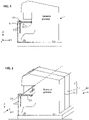
- the figures 1 and 2 represent a machine processing food product containers. It can be dairy products, syrups, drinks of all kinds, even pasty or powdered products.
- the present invention applies in fact to any food product.
- these machines/equipment/lines make it possible to fill containers, for example jars or bottles, with one or more food products, for example a dairy product and/or food components, and to seal these containers.
- marking, labeling and prior disinfection operations may optionally be provided. However, any other operation is not excluded.
- FIG. 1 and 2 processing modules juxtaposed in the axial direction of the machine marked respectively 71 , 72 , 7i .
- the different processing modules or process modules are collectively identified by the reference 7 .
- Supports which we will call support plates , or even simply plates , are used to support the containers during the operations carried out in the machine.
- the handling system comprises a first section TC1 , called work.
- the handling system includes a second section TC2 , called rapid return.
- each support plate 1 is loaded with empty containers, and at another point, downstream, the filled containers are removed from the support plate 1.
- Each support plate 1 comprises one or more housings 18 , each housing 18 being capable of receiving a container.
- the container is received from above, in which case it is by the effect of gravity that an upper edge 58 of the container bears on an edge of the housing.
- the housing may be formed as an orifice.
- the container is typically a pot 5 with a flange 58 wider than its body.
- the container can be received by lateral insertion, a neck of the container is housed in a housing having a mouth and a strait. After the neck of the container has passed through the strait, the container remains retained in a hole of a size corresponding to the size of the neck.
- the container is typically a bottle with a neck and a neck.
- the number of slots can be 4 or 8. However, the number of slots can be any, from 2 to 16.
- the handling system comprises a first end E1 and a second end E2 .
- a first rotation station PR1 arranged at the first end E1 , configured to rotate the support plates towards the horizontal position, to engage them on the first section TC1 .
- a second rotation station PR2 arranged at the second end E2 , configured to rotate the support plates towards the return orientation to engage them on the second section TC2 .
- the longitudinal work axis (ie of the machine) is denoted X ; a longitudinal reference axis of the handling system denoted X1 is defined.
- the transverse axis of the machine is denoted Y the local vertical axis is denoted Z.
- the entire handling system is supported by a general support frame marked 6 (represented only generically in Figures 1, 2 and 17 ).
- the X1 axis is located on the outside of the machine, ie the plates 1 in the TC1 section are between the X1 axis and the process modules 7.
- the X1 axis is located on the inside of the machine, ie the X1 axis is between the plates 1 on TC1 and the process modules 7 .
- each support plate 1 extends generally in a reference plane PR , with a generally rectangular shape.
- Each support plate comprises two short sides marked 13 and 14 respectively, parallel to the Y direction of the machine.
- Each support plate has two long sides parallel to the longitudinal direction X of the machine, namely a first long side 11 forming a guide and maneuver edge, and another long side 12 forming a free edge.
- the longitudinal length denoted PX is here between 400 mm and 480 mm. However, more generally, the length PX can be between 250mm and 880mm, or else between 360mm and 520mm.
- the width of the plate noted LW here between 250 mm and 350 mm. However, more generally, the width LW can be between 200 mm and 500 mm.
- Each support plate is made from a single piece. Each support plate is flat.
- the thickness of an EPP plate can typically be between 1 and 3 mm. Typically, the starting point is a sidewall of constant thickness and the notches and grooves which will be discussed below are fitted therein. According to one example, the EPP thickness can be 8 mm. According to another example, the EPP thickness can be between 6 mm and 8 mm.
- Each support plate 1 comprises an upper face 1A and a lower face 1B .
- Each support plate 1 can be made of stainless steel or of a food-compatible metal alloy. However, a material of the food-compatible hard plastic type such as polypropylene or polycarbonate could also be suitable.
- the support plates circulate in a horizontal position in a first axial direction X1A .
- the plates are adjacent to each other in the first section. However, it is not excluded that they are slightly spaced from each other.
- the support plates advance in a second axial direction X1B opposite to the first axial direction.
- the support plates circulate in a posture or orientation which is different from the horizontal position.
- the term "return orientation" is used for this posture. Said return orientation is vertical in the example shown. In a variant not shown, the return orientation can be angularly distant from the vertical by less than 30 degrees, that is to say not very far from the vertical position.
- the first long side 11 forms a guide and maneuver border.
- the guidance and drive functions are located in the vicinity of this long side.
- the edge corresponding to this long side is received in one or more grooves for guiding and receiving guides and rotary bases as will be described later.
- the opposite edge 12 is only guided but not driven.
- the motorization is thus relatively simple and is located in the vicinity of the longitudinal axis X1 of the handling system.
- the opposite long edge 12 can be supported by an auxiliary guide 44 .
- This auxiliary guide can be continuous or discontinuous; as illustrated figure 9 , this auxiliary guide 44 can be carried by an arm 70 integral with one of the aforementioned process modules 7i .
- This auxiliary guide 44 is preferably removable.
- housings provided in the support plate can be round or square depending on the shape of the pots to be treated.
- Each support plate comprises at least one notch 16 to receive a finger of the first displacement member.
- the notch or notches 16 is (are) preferably through (s) on the thickness of the plate. This is easy to clean and prevents dirt from getting lodged in a blind hole.
- each support plate comprises two notches.
- a projection 15 forming an out-of-plane projection, which serves to retain the plate in particular in its vertical orientation.
- a longitudinal groove marked 19 is used to hold the plate in which is housed a longitudinal rib 28 , 29 provided in the means for guiding the plates.
- auxiliary notches marked 10 may be provided, the usefulness of which, in particular in the vertical position, will be seen later.
- the plate may have a generally square shape instead of a rectangle.
- short sides are not necessarily straight, they can include a convex or concave drop.
- first member 2 for moving the support plates along the first axial direction X1A .
- first member 2 is of the stepper type.
- any type of displacement mechanism can be envisaged within the scope of the present invention.
- the first displacement member 2 comprises in the example illustrated a transfer bar 21 which generally extends along the axial direction and is pivotally mounted around the axis X1 .
- the transfer bar 21 of the first displacement member 2 comprises a finger 26 at a distance from the axis X1 and configured to be received in a notch 16 of the plate, the empty return of the finger being carried out while the finger 26 is not not engaged.
- the transfer bar 21 of the first displacement member 2 operates with two degrees of freedom, namely a rotation around X1 and an advancement in the axial direction.
- the rotation allows the engagement and disengagement of the finger 26 in a notch 16 .
- the axial translation makes it possible to advance by a predetermined distance one or more plates on the first section.
- the predetermined distance coincides with the axial length of the plate, that is to say the pitch PX .
- the advance distance at each movement of the transfer bar can be PX/2 .
- the advance distance at each movement of the transfer bar can be PX/4 .
- the axial translation is carried out either by a worm screw and prisoner nut mechanism, or by a rack and pinion mechanism, or even by means of a long-stroke electric cylinder. It is generally possible to use any axial translation mechanism known per se.
- an axis shaft denoted 22 which can be fixed or integral with the transfer bar itself.
- the device also comprises a motor denoted M2 , or a geared motor, which is placed in the vicinity of the axle shaft.
- An output pinion engages on a rack or a helical toothing to move the transfer bar 21 along the longitudinal direction X1, with rotation of the axis shaft 22 or not depending on the possible configurations.
- the transfer bar is equipped with a marked rear lever 25 integrally connected to the transfer bar body; the rear lever 25 is received in a sliding connection 27 .
- the rear lever 25 can thus slide along X1 in the slide 27 longitudinally.
- a single-acting control cylinder denoted M1 as well as a return spring 45 .
- the return spring has the effect of tilting the transfer bar around the axis X1 towards the disengaged position of the control finger 26, while conversely the actuation of the cylinder M1 has the effect of tilting the transfer bar in the opposite direction and engage the control finger in the notch 16.
- first displacement member 2 can be described as a “transfer shuttle”. Any other solution for causing at least one plate to advance over a predetermined distance can also be envisaged.
- the transfer shuttle simultaneously engages all the plates located on the working section TC1 .
- the transfer bar 21 and the axis shaft 22 run almost the entire length of the handling system except where appropriate the ends.
- the plates do not push each other and are not necessarily adjacent. This also makes it possible to operate the machine under test with only a few plates.
- the transfer shuttle engages only the first plate located at the start of the first section and the plates push each other until the end of the first section.
- the axis shaft and the transfer bar are then much shorter, that is to say the order of magnitude corresponds to the length of a PX plate or a little more.
- the transfer shuttle can work from below as shown in figure 14 and 15 , as illustrated below.
- the transfer bar 21 is located below the upper face 1A of the plates in the working section, the zone located above the work surface marked PW is free of any element which may present a pollution risk nuisance.
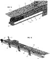
- the handling system comprises a second displacement member 3 configured to move the support plates in the second axial direction X1B in the second section TC2 .
- the second displacement member is preferably of the continuous type.
- the second moving member comprises an endless belt marked 34 .
- This belt is guided and driven by two grooved pulleys, including a leading pulley 32 driven by a motor M3 and a follower pulley 33 at the other end of the belt.
- the belt rubs against the underside 1B of the plates, in the return orientation posture, namely in the vertical position, to drive them from the second end E2 towards the first end E1 .
- the belt can act by friction against the plates or, alternatively, the belt can be double-toothed. In the latter case, there is an internal toothing for driving the belt by a drive pulley and an external toothing for driving the support plates by the belt on the return section TC2.
- the second displacement member can be formed by a chain with articulated links mounted in a loop on two toothed sprockets at the ends.
- a first toothed pinion is driving, and the other is mounted on a support elastically returned by spring to tend to maintain sufficient tension on the chain at all times.
- Skids fixed on the outside of certain links of the loop chain can be provided to come to rest on the plates in their vertical posture and drive the plates.
- a working strand 34a is arranged in contact with the plates which are located on the second section while a return strand 34b is at a distance from the plates and is used for the empty return.
- the feed rate of the working side of the belt is relatively fast. In practice it is at least equal to the forward speed of the transfer bar in the opposite direction.
- the forward speed of the belt 34 can be at least equal to 500 mm per second.
- the motorization of the plates on the second section could be different from that illustrated, for example a system with impulse, return by gravity, or any other solution made possible by the fact that there is no work operation on the plates on this return leg.
- the first rotation station PR1 comprises a first rotating base 41 on the side of the first end E1 .
- the first rotating base pivots the support plates towards the horizontal position, to engage them on the first section TC1.
- the first rotating base can be formed as an element mounted for rotation around an axis coinciding with X1 or close to the latter, this element being driven in angular position by a geared motor with two limit sensors or a stepper motor with a limit switch.
- the first rotating base 41 is therefore movable between a first position suitable for receiving a support plate arriving on the second section in a return orientation and a second position suitable for placing a support plate in a horizontal position at the entrance to the first section.
- an erasable stop 49 which subordinates the entry of a vertical plate back into the rotating base 41 to a vertical reception position of this rotating base.
- the erasable stop 49 is selectively controlled by a small actuator M4 .
- the erasable stop can be a form integrated into the side of the rotating base 41 , without requiring a specific command other than the rotation of the rotating base 41 .
- the second rotation station PR2 On the side of the second end E2 , the second rotation station PR2 comprises a second rotating base 42 .
- the second rotating base rotates the support plates towards the return orientation to engage them on the second section TC2 .
- the second rotating base can be formed as an element mounted for rotation around an axis coinciding with X1 or close to the latter, this element being controlled in angular position by a geared motor with two limit switches or a stepper motor with a limit switch. If the way is clear, the second rotating base pivots the plate in the vertical position and inserts it immediately into the second return section TC2 .
- Each of the rotating bases comprises a groove for receiving the longitudinal edge, ie the large side 11 forming a guide and maneuver edge.
- Both the first rotary base and the second rotary base include means for retaining the plates.
- the rotating bases include a housing forming slides to receive this in-plane projection (Cf figure 11 ).
- each support plate 1 has a guide groove 19.
- the rotating bases comprise a projecting rib 29 on which bears inside the groove 19 provided in the plates. (see Figs 13 and 14 lower part).
- a fixed main guide support 40 is provided, arranged continuously along the first axial direction X1A , between the first and second rotating bases 41 , 42 .
- the support is thus continuous for the plates from the first end E1 to the second end E2 .
- the main guide support comprises a rib 28 which allows the longitudinal guiding of the plates, the rib 28 being received in the groove 19 .
- the main guide support is formed as a profile with a generally constant section along X1 .
- the main guide support 40 forms a guide rail.
- This rail/profile makes it possible, on the one hand, to guide plates in a horizontal position which transit in the first section TC1 , and on the other hand to guide plates in a vertical position in the second section TC2 where they circulate in return.
- This type of system with support plates can also be used in machines or installations that treat containers of non-food products to which the present invention can be applied.
- the plates are moved sequentially from one station to another by the first moving member 2 described above.
- the plates are in the horizontal position, mark 1H in figures 15 and 16 .
- various operations are carried out at a fixed station, in the time interval between the forward movements of the transfer bar.
- metering nozzles marked 77 are provided, located at the location of one of the positions of the plate.
- the second rotating base 42 performs a rotation of each support plate 1 around the longitudinal reference axis X1 by an angle ⁇ (90° in a typical case). Following which, each plate traverses the return section substantially keeping this orientation.
- the plates are in the vertical position, mark 1V in figures 15 and 16 .
- the plates are moved along the second section TC2 by the second moving member 3 described above.
- the first section TC1 is completely occupied by the plates, while the second section TC2 comprises only a few plates, as this is visible from the figure 16 .
- the number of plates on the first section can be between ten and thirty depending on the configuration of the machine.
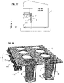
- the figure 18 illustrates a variant where a special case is used for containers that do not have a collar.
- the container does not rest directly on the plate but on a shoe 79 arranged at a distance under the plate, this distance corresponding to the height of the container 5 to be treated.
- This shoe is connected to the plate by four columns 78 .
- the plates are made in two parts, namely on the one hand a flat plate denoted 1 ' with the housings 18 and on the other hand a technical profile 17 for the guiding and driving functions.
- the technical profile 17 for guiding and driving comprises a guide groove 190 whose functions are identical to the groove 19 previously described.
- the technical profile 17 for guiding and driving comprises two notches 160 arranged on the edge of the plate, side of the large side.
- the technical profile 17 has a length PX identical to the longitudinal dimension of the plate PX .
- the flat plate 1' is obtained from a blank in which holes are made, so it is easy to make.
- the technical profile 17 is fixed under the plate, ie fixed to the underside 1B of the plate 1 '. None protrudes from the upper plane 1A of the plate.
- the technical profile 17 is obtained by plastic molding.
- the installation includes a system for loading and unloading the support plates.
- provision is made to be able to unload the support plates present in the looped circuit of the machine, in the direction of a pallet for receiving the support plates generally marked 9 in the figures.
- this receiving pallet is brought to the level of the station of the first rotation station. In the example shown, it is installed under the first rotating base 41 .
- the receiving pallet 9 receives the support plates one after the other from the second section TC2 of the handling system.
- the receiving pallet includes a plurality of slots 94 .
- each of these locations are presented as grooves parallel to the longitudinal axis X of the machine, we also speak of a 'slot' to qualify a location.
- the transverse offset between the grooves represents a distance P9 (see figure 21 and 24 ).
- the distance P9 can be between 10 mm and 50 mm.
- the distance P9 can be between 1.5 EPP and 2.5 EPP, EPP representing the general thickness of the plate.
- each support plate there may be provided complementary shapes of the marked notches 10 formed on the free edge 12 of each support plate. These complementary shapes allow indexing of the plates on the pallet in the longitudinal direction X. These lateral notches 10 can also be used for indexing purposes on the treatment stations.
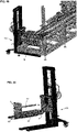
- retaining post 92 with slots to hold the plates in a vertical position, as shown in figure 21 .
- the retaining post also forms a stop in the bottom insertion movement of the support plate on the pallet along X.
- the receiving pallet 9 comprises a number of slots comprised between 16 and 32.
- the number of slots could be lower than these values or higher than these values.
- a frame 90 is provided on which the pallet can slide, the frame being arranged in a fixed position during the changing or unloading operation.
- a slide system 96 makes it possible to slide the pallet relative to the frame.
- equipment of the pallet truck type 100 is provided to support the pallet during the operation or to recover the pallet after the operation (in this case the frame 90 supporting the pallet can be placed and indexed on the general frame 6 of the handling system.
- the pallet is shifted by a distance P9 in the transverse direction Y to align an empty space opposite the arrival of the plates vertically.
- Another plate then arrives and is inserted into the available location, and so on.
- the first rotary base 41 remains in its horizontal position, that is to say in its second position.
- the complementary shapes in the rotating base provided to maintain a plate arriving in a vertical position have no effect here.
- the plate is thus freed from the guide forms, because there is in fact no rib 29 arranged to engage in the groove 19 at this location (in fact the rotating base is in the horizontal position and not in the vertical position as in normal operation).
- the erasable stop 49 makes it possible to wait for the plates waiting for the time that the pallet is shifted along Y to align an empty space in front of the first plate pending.
- the support plates are initially stored in the locations 94 of the receiving pallet which is located at the end of the second section TC2 in the vicinity of the first end E1 of the handling system.
- the first rotating base 41 remains in its second position, namely the horizontal position.
- the belt conveyor that is to say the second displacement member 3 , is operated in the opposite direction to the usual direction in order to bring up the first plate which is in position adjacent to the belt conveyor, and engages in the guide main 40 where the rib 29 engages in the groove 19 at this location.
- We have thus engaged the slide guide along the second section TC2 the only difference compared to the normal mode and that the plates progress in the opposite direction.
- the movement of the belt is stopped and the pallet is shifted by a distance P9 to put a new support plate in contact with the belt 34 . Then the process is repeated, namely the belt is driven in the opposite direction to the normal direction to make this plate go up against the grain on the second section and occasionally push back the plate which was introduced previously.
- the receiving pallet could be installed at the level of the second rotation station PR2 , namely under the second rotating base 42 .
- the second displacement member 3 and of the second rotating base it would also be possible to unload all of the support plates onto the receiving pallet at the second end of the handling system, and also to proceed with the reloading of a new set of support plates at this location.
- a greater spacing P9 can be provided to allow a translation along X to operate when the plates 1 are unloaded on the pallet.
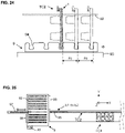
- the figure 25 illustrates, seen from above, a second possibility, consisting of a progressive exchange of the batch of plates; in this case, an 'old' plate is unloaded and a 'new' plate is installed in its place. This unit operation is repeated (unloading + reloading) as many times as there are plates. When all the plates have been replaced, the pallet filled with the old plates can be moved away.
- a locating/alignment system makes it possible to simplify the installation.
- a manipulator 97 is provided.
- the manipulator 97 can be a cylinder equipped with a clamp at the end of the rod, to pull and/or push a plate vis-à-vis a location on the second section TC2.
- the manipulator is driven in conjunction with the shift mechanism 93 which Y-shifts the pallet locations as mentioned above.
- a plate 95 is in a position ready for unloading, the manipulator 97 advances then seizes it then pulls it onto the empty space of the pallet, this plate will join the batch of plates already unloaded 98 .
- the shift mechanism 93 shifts along Y (upwards in the figure) the pallet with respect to the frame supporting the pallet.
- the manipulator 97 pushes the plate which is there from the location of the pallet towards the guides of the second section.
- the handling system moves the plates and brings an old plate to the position ready for unloading. The operations are repeated in this way until all the plates have been replaced.
Landscapes
- Engineering & Computer Science (AREA)
- Mechanical Engineering (AREA)
- Specific Conveyance Elements (AREA)
- Discharge By Other Means (AREA)
- Auxiliary Devices For And Details Of Packaging Control (AREA)
- Reciprocating Conveyors (AREA)
- Warehouses Or Storage Devices (AREA)
- Feeding Of Workpieces (AREA)
- Delivering By Means Of Belts And Rollers (AREA)
- Stacking Of Articles And Auxiliary Devices (AREA)
- De-Stacking Of Articles (AREA)
- Sheets, Magazines, And Separation Thereof (AREA)
Applications Claiming Priority (1)
| Application Number | Priority Date | Filing Date | Title |
|---|---|---|---|
| FR2103974A FR3121921B1 (fr) | 2021-04-16 | 2021-04-16 | Système de chargement et déchargement de plaques dans une machine traitant des récipients |
Publications (1)
| Publication Number | Publication Date |
|---|---|
| EP4079662A1 true EP4079662A1 (de) | 2022-10-26 |
Family
ID=76375212
Family Applications (1)
| Application Number | Title | Priority Date | Filing Date |
|---|---|---|---|
| EP22168660.3A Withdrawn EP4079662A1 (de) | 2021-04-16 | 2022-04-15 | System zum be- und entladen von platten in einer maschine, die behälter bearbeitet |
Country Status (12)
| Country | Link |
|---|---|
| US (1) | US11685611B2 (de) |
| EP (1) | EP4079662A1 (de) |
| JP (1) | JP7309008B2 (de) |
| KR (1) | KR20220143602A (de) |
| CN (1) | CN115215277A (de) |
| AR (1) | AR125707A1 (de) |
| BR (1) | BR102022007235A2 (de) |
| CA (1) | CA3155595A1 (de) |
| CL (1) | CL2022000966A1 (de) |
| FR (1) | FR3121921B1 (de) |
| IL (1) | IL292231A (de) |
| MX (1) | MX2022004591A (de) |
Families Citing this family (2)
| Publication number | Priority date | Publication date | Assignee | Title |
|---|---|---|---|---|
| US12246925B2 (en) * | 2022-08-12 | 2025-03-11 | Simec Systems Oy | Hauling beam and a hauling transporter |
| CN118495100B (zh) * | 2024-07-18 | 2024-09-20 | 江苏晶雪节能科技股份有限公司 | 一种冷库门智能自动化生产用输送设备及方法 |
Citations (2)
| Publication number | Priority date | Publication date | Assignee | Title |
|---|---|---|---|---|
| EP0995700A1 (de) * | 1998-10-21 | 2000-04-26 | Isap Omv Group S.P.A. | Schabloneförderer in einer Warmformpresse |
| EP2070843A1 (de) * | 2007-12-11 | 2009-06-17 | Gerhard Schubert GmbH | Verfahren und Vorrichtung zum Transportieren von Objekten |
Family Cites Families (23)
| Publication number | Priority date | Publication date | Assignee | Title |
|---|---|---|---|---|
| US770570A (en) * | 1904-09-20 | Coupling-head for soda-tanks | ||
| US1106541A (en) * | 1913-09-02 | 1914-08-11 | James Wesley Bruce | Agricultural implement. |
| US2870900A (en) * | 1955-01-26 | 1959-01-27 | William B Will | Construction elevator |
| US4627530A (en) * | 1983-10-20 | 1986-12-09 | Universal Conveyor Co., Inc. | Elevating chain conveyor |
| JPS6356119U (de) | 1986-09-30 | 1988-04-14 | ||
| JPH0318009U (de) | 1989-07-03 | 1991-02-22 | ||
| US5141128A (en) * | 1991-06-13 | 1992-08-25 | Electrocom Automation, Inc. | Reconfigurable vertical conveyor dispenser |
| JP3356527B2 (ja) | 1994-01-21 | 2002-12-16 | 芝浦メカトロニクス株式会社 | パレット移送装置 |
| KR100188352B1 (ko) * | 1995-10-25 | 1999-06-01 | 니시모토 간이치 | 소터 |
| US20030226744A1 (en) * | 1997-12-30 | 2003-12-11 | Uffe Lykkegaard | Conveyor |
| JP4314657B2 (ja) * | 1999-02-10 | 2009-08-19 | 澁谷工業株式会社 | スクリュー搬送装置 |
| JP2001157935A (ja) * | 1999-12-02 | 2001-06-12 | Sumitomo Wiring Syst Ltd | 昇降式台車搬送装置 |
| JP4307978B2 (ja) | 2003-12-16 | 2009-08-05 | 花王株式会社 | 容器の搬送装置 |
| WO2011072628A1 (de) * | 2009-12-14 | 2011-06-23 | Hamba Filltec Gmbh & Co. Kg | Vorrichtung zum befüllen von behältern |
| DE102011103256A1 (de) * | 2011-05-25 | 2012-11-29 | Hamba Filltec Gmbh & Co. Kg | Vorrichtung zum Befüllen von Behältern |
| CN103058111B (zh) * | 2012-10-24 | 2014-12-17 | 杭州中亚机械股份有限公司 | 一种直线灌装设备的夹持容器输送装置 |
| EP2733092B1 (de) * | 2012-11-20 | 2014-12-31 | Comau S.p.A. | Stauförderer zum Transport von Paletten in einem horizontalen Karussell und Verfahren zur Kontrolle eines solchen Förderers |
| US10363698B2 (en) * | 2013-10-21 | 2019-07-30 | Discma Ag | Machine for forming and filling containers comprising a first closed loop and a second closed loop having a common part |
| US10696488B2 (en) * | 2018-05-29 | 2020-06-30 | The Procter And Gamble Company | Apparatus that controls motion of proximate independent movers along a path |
| US10399257B1 (en) * | 2018-07-18 | 2019-09-03 | Alex Xie | Controlled vertical material distribution |
| CN208762115U (zh) * | 2018-08-20 | 2019-04-19 | 成都味科自动化设备有限公司 | 一种用于自动灌装流水线的灌装定位系统 |
| CN110844862B (zh) * | 2019-11-19 | 2021-08-06 | 广州二广生物科技有限公司 | 一种洗发水及其加工工艺与加工系统 |
| IT202000008479A1 (it) * | 2020-04-21 | 2021-10-21 | Kosme Srl Unipersonale | Dispositivo di trasporto per il trasporto di contenitori |
-
2021
- 2021-04-16 FR FR2103974A patent/FR3121921B1/fr active Active
-
2022
- 2022-04-11 CA CA3155595A patent/CA3155595A1/en active Pending
- 2022-04-13 MX MX2022004591A patent/MX2022004591A/es unknown
- 2022-04-13 IL IL292231A patent/IL292231A/en unknown
- 2022-04-14 CL CL2022000966A patent/CL2022000966A1/es unknown
- 2022-04-14 BR BR102022007235-3A patent/BR102022007235A2/pt unknown
- 2022-04-15 KR KR1020220046982A patent/KR20220143602A/ko not_active Ceased
- 2022-04-15 CN CN202210393861.5A patent/CN115215277A/zh active Pending
- 2022-04-15 EP EP22168660.3A patent/EP4079662A1/de not_active Withdrawn
- 2022-04-15 US US17/721,520 patent/US11685611B2/en active Active
- 2022-04-18 JP JP2022068173A patent/JP7309008B2/ja active Active
- 2022-04-18 AR ARP220100982A patent/AR125707A1/es active IP Right Grant
Patent Citations (2)
| Publication number | Priority date | Publication date | Assignee | Title |
|---|---|---|---|---|
| EP0995700A1 (de) * | 1998-10-21 | 2000-04-26 | Isap Omv Group S.P.A. | Schabloneförderer in einer Warmformpresse |
| EP2070843A1 (de) * | 2007-12-11 | 2009-06-17 | Gerhard Schubert GmbH | Verfahren und Vorrichtung zum Transportieren von Objekten |
Also Published As
| Publication number | Publication date |
|---|---|
| CN115215277A (zh) | 2022-10-21 |
| KR20220143602A (ko) | 2022-10-25 |
| MX2022004591A (es) | 2022-10-17 |
| CA3155595A1 (en) | 2022-10-16 |
| FR3121921B1 (fr) | 2023-03-31 |
| US20220332517A1 (en) | 2022-10-20 |
| JP2022164653A (ja) | 2022-10-27 |
| CL2022000966A1 (es) | 2022-10-28 |
| US11685611B2 (en) | 2023-06-27 |
| FR3121921A1 (fr) | 2022-10-21 |
| IL292231A (en) | 2022-11-01 |
| AR125707A1 (es) | 2023-08-09 |
| BR102022007235A2 (pt) | 2022-10-25 |
| JP7309008B2 (ja) | 2023-07-14 |
Similar Documents
| Publication | Publication Date | Title |
|---|---|---|
| EP3802377B1 (de) | Überführen von produkten durch einfassing aus oder zu einem speicherbereich | |
| EP1984256B1 (de) | Verfahren und anlage zur montage palettierbarer produkte | |
| EP2196395B1 (de) | Vorrichtung und Verfahren zur Verpackung von Spritzen in Nestern | |
| EP4079662A1 (de) | System zum be- und entladen von platten in einer maschine, die behälter bearbeitet | |
| EP4074632A1 (de) | Fördergeräte in einer maschine, die behälter bearbeitet | |
| WO2019129968A1 (fr) | Déplacement de produits sur une zone de transit | |
| FR3083532A1 (fr) | Dispositif de transfert perfectionne | |
| CA3058100A1 (fr) | Transfert multilignes de produits | |
| FR3092574A1 (fr) | Système et procédé de manipulation d'articles tels que récipients à boisson ou similaire | |
| EP4074633A1 (de) | System zur handhabung von platten in einer maschine, die behälter bearbeitet | |
| FR2802903A1 (fr) | Redresseur de bouteilles, flacons et autres contenants allonges en vue de leur remplissage | |
| FR3041888A1 (fr) | Machine et procede de revetement de peinture pour profiles pvc | |
| FR3086646A1 (fr) | Trajet de transport destiné à transporter une pluralité d'articles et procédé destiné à adapter et/ou à faire fonctionner un tel trajet de transport | |
| FR2622178A1 (fr) | Dispositif de changement pour produits de grande longueur sur un transporteur a rouleaux | |
| EP0486360B1 (de) | Dynamische Speichervorrichtung für Behälter in einer pneumatisch betriebenen Transferstrasse | |
| FR2652802A1 (fr) | Dispositif de transport pour plaques, en particulier a surface sensible. | |
| EP0042463B1 (de) | Selbsttätige Förderanlage | |
| EP1762308A2 (de) | Flaschenreinigungsvorrichtung | |
| WO2018072886A1 (fr) | Dispositif et procédé de déviation et d'échantillonnage pour élément en plaque | |
| EP1300224B1 (de) | Maschine für das Fertigstellen von geklebten Korken | |
| FR3119606A1 (fr) | Dispositif et procédé de transport d'articles, tels que de récipients à boisson ou similaires | |
| FR2473998A1 (fr) | Magasin a cassettes pour alimenter des machines a bobiner des bandes magnetiques | |
| FR3046999A1 (fr) | Dispositif et methode de transfert de produits | |
| FR2666562A1 (fr) | Dispositif de transfert d'articles divers en vue de leur conditionnement. | |
| FR2508423A1 (fr) | Dispositif pour la manipulation de boites, notamment de boites de conserves |
Legal Events
| Date | Code | Title | Description |
|---|---|---|---|
| PUAI | Public reference made under article 153(3) epc to a published international application that has entered the european phase |
Free format text: ORIGINAL CODE: 0009012 |
|
| STAA | Information on the status of an ep patent application or granted ep patent |
Free format text: STATUS: THE APPLICATION HAS BEEN PUBLISHED |
|
| AK | Designated contracting states |
Kind code of ref document: A1 Designated state(s): AL AT BE BG CH CY CZ DE DK EE ES FI FR GB GR HR HU IE IS IT LI LT LU LV MC MK MT NL NO PL PT RO RS SE SI SK SM TR |
|
| STAA | Information on the status of an ep patent application or granted ep patent |
Free format text: STATUS: REQUEST FOR EXAMINATION WAS MADE |
|
| 17P | Request for examination filed |
Effective date: 20230403 |
|
| RBV | Designated contracting states (corrected) |
Designated state(s): AL AT BE BG CH CY CZ DE DK EE ES FI FR GB GR HR HU IE IS IT LI LT LU LV MC MK MT NL NO PL PT RO RS SE SI SK SM TR |
|
| GRAP | Despatch of communication of intention to grant a patent |
Free format text: ORIGINAL CODE: EPIDOSNIGR1 |
|
| STAA | Information on the status of an ep patent application or granted ep patent |
Free format text: STATUS: GRANT OF PATENT IS INTENDED |
|
| RIC1 | Information provided on ipc code assigned before grant |
Ipc: B65G 35/06 20060101ALI20230804BHEP Ipc: B65G 25/02 20060101AFI20230804BHEP |
|
| INTG | Intention to grant announced |
Effective date: 20230829 |
|
| STAA | Information on the status of an ep patent application or granted ep patent |
Free format text: STATUS: THE APPLICATION IS DEEMED TO BE WITHDRAWN |
|
| 18D | Application deemed to be withdrawn |
Effective date: 20240109 |