EP1762308A2 - Flaschenreinigungsvorrichtung - Google Patents
Flaschenreinigungsvorrichtung Download PDFInfo
- Publication number
- EP1762308A2 EP1762308A2 EP06360036A EP06360036A EP1762308A2 EP 1762308 A2 EP1762308 A2 EP 1762308A2 EP 06360036 A EP06360036 A EP 06360036A EP 06360036 A EP06360036 A EP 06360036A EP 1762308 A2 EP1762308 A2 EP 1762308A2
- Authority
- EP
- European Patent Office
- Prior art keywords
- bottles
- magazines
- conveyor belt
- cleaning machine
- gripping
- Prior art date
- Legal status (The legal status is an assumption and is not a legal conclusion. Google has not performed a legal analysis and makes no representation as to the accuracy of the status listed.)
- Withdrawn
Links
Images



Classifications
-
- B—PERFORMING OPERATIONS; TRANSPORTING
- B08—CLEANING
- B08B—CLEANING IN GENERAL; PREVENTION OF FOULING IN GENERAL
- B08B9/00—Cleaning hollow articles by methods or apparatus specially adapted thereto
- B08B9/08—Cleaning containers, e.g. tanks
- B08B9/20—Cleaning containers, e.g. tanks by using apparatus into or on to which containers, e.g. bottles, jars, cans are brought
- B08B9/28—Cleaning containers, e.g. tanks by using apparatus into or on to which containers, e.g. bottles, jars, cans are brought the apparatus cleaning by splash, spray, or jet application, with or without soaking
- B08B9/30—Cleaning containers, e.g. tanks by using apparatus into or on to which containers, e.g. bottles, jars, cans are brought the apparatus cleaning by splash, spray, or jet application, with or without soaking and having conveyors
Definitions
- the present invention relates to the field of the packaging of liquids, in particular in bottle-shaped containers and in particular glass bottles and other containers such as carafes or the like and more particularly the prior cleaning of such bottles and relates to a machine of cleaning such containers.
- new bottles, carafes and the like are packaged in the factory on pallets separated from each other by a layer of cardboard, the assembly being held under a cover of heat-shrinkable synthetic material.
- bottles and the like thus conditioned can not therefore be filled directly without prior cleaning, because condensation often forms during the storage of the latter and there is also the presence of insects, glass debris, or even unwanted odors may emanate packaging materials surrounding said bottles, carafes or the like namely the odors of cardboard or synthetic material.
- the bottles or the like are rinsed with running water, optionally supplemented with a sterilizer product. This rinsing can be done by hand or automatically or semi-automatically.
- the second method consists of simultaneously pushing several bottles out of the transport chain and placing them in a row of buckets which are mounted in a vertical wheel whose axis is horizontal, the necks being directed towards said axis.
- the buckets are arranged all around the wheel which plunges by its lower half, into a tray filled with a sterilizing solution, usually based on S02.
- the hourly production capacity of known methods and devices can be obtained only by the number of grippers grasping the bottles and, consequently, only by enlarging the carousel, which very quickly poses a problem of space and a problem of manufacturing cost.
- the bottles are in the inverted or inverted position only for a short fraction of their journey with respect to a complete turn of the wheel, so that a dewatering satisfactory is difficult to obtain.
- Machines for carrying out these operations are known in particular by FR-A-2,417,469 , DE-C-719 735 , US-A-2,826,207 , US-A-3,064,663 and GB-A-293,324 . These known machines, however, have the disadvantage of allowing, in addition, an individual transfer bottles or the like of the transport device to the treatment station and vice versa.
- the present invention aims to overcome the aforementioned drawbacks.
- a machine for cleaning bottle-shaped containers and especially glass bottles and other containers consisting of a conveyor belt for the bottles or the like displacing the latter at a constant and constant speed, from a catch area of the bottles or the like to be treated to a deposit zone for bottles or the like treated, a bottle spacing device or the like mounted upstream of the bottle engaging zone or the like of said cleaning machine, and a set of receiving and holding magazines for bottles or the like during their treatment, characterized the fact that the magazines move in a sequential cycle and that a single means of taking, depositing and transferring bottles or the like in batches, between the conveyor belt and the set of magazines, provides the interface between the magazines and the conveying belt and the continuity of the flow of said bottles or the like, on the conveyor belt, between the gripping zones and the e deposit bottles or the like.
- the attached figures show a cleaning machine 1 according to the invention constituted by a conveying belt 4 of bottles 2 or the like displacing the latter at a constant and continuous speed, from a gripping zone P of the bottles 2 or the like to be processed up to at a deposition zone D of the treated bottles 2 or the like, a spacer 8 of the bottles 2 or the like mounted upstream of the gripping zone P of the bottles 2 or the like of said cleaning machine 1, and a set of magazines 6 receiving and holding bottles 2 or the like during their treatment.
- bottles 2 In the remainder of the description only reference will be made to bottles 2. However, it is obvious that the invention is also applicable to other containers such as carafes or the like.
- the magazines 6 move in a sequential cycle and a single means 2 for taking, depositing and transferring the bottles 2 in batches, between the conveyor belt 4 and the set of magazines 6, provides the interface between the magazines 6 and the conveyor belt 4 and the continuity of the flow of said bottles 2, on the conveyor belt 4, between the P and deposition zones D of the bottles 2.
- the duration of the treatment is generally longer than the speed of movement of the conveyor belt 4, so that many known devices mark downtime to compensate for this difference.
- the magazines 6 can be mounted on a guide frame 9 in two rows of parallel magazines 6 and can be movable on said guide frame 9, on the one hand, perpendicularly to the conveyor belt 4 and in the opposite direction a row of magazines 6 to the other and, on the other hand, at both ends of the guide frame 9, in opposite directions from one row to the other, parallel to the conveyor belt 4, the total number of stores being an even and lower number of two units to the total number of magazines 6 can be mounted in the guide frame 9, the assembly can thus move in an endless cycle.
- the number of magazines 6 of bottles 2 and the bottle receiving capacity 2 of said magazines 6 determine the processing capacity of the cleaning machine 1. This number is even, in order to leave a gap in each row of magazines 6 parallel to each the time of the cycle of movement of the magazines 6 in the guide frame 9 in a sequential operation to allow the displacement of said magazines 6 in the opposite direction in the latter. There remains therefore, at any time of the magazine movement cycle 6, a vacuum in each row of magazines 6, the dimensions of which correspond to those of a magazine 6.
- the magazines 6 may be in the form of rectangular blocks provided, at regular intervals, through holes 10 for receiving and centering bottles 2 by their neck.
- the guide frame 9, shown in FIGS. 2A and 2B can be connected at one end to the simultaneous loading and unloading means 7 of bottles 2 and can be substantially in the form of a rectangular guiding outer frame consisting of two longitudinal members 11 and 12 perpendicular to the conveyor belt 4 connected at their ends by two crosspieces 13 and 14, one of which, 13, extends adjacent to the loading and simultaneous unloading 7 of bottles 2, a median spar 15 for guiding and separating the two rows of magazines 6 that can be provided in the median part of the guide frame 9.
- the realization of the guide frame 9 in the form of a rectangular frame makes it possible to reduce as much as possible the space occupied by the latter, and therefore the space dedicated to the cleaning of the bottles 2, while allowing a high cleaning capacity of the bottles 2.
- the guide frame 9 shown in Figure 7 may, for example, receive twelve stores 6 and will present a circulation space of said stores 6 corresponding to the size of fourteen stores. Each of these stores can receive, in turn, three bottles 2 to clean.
- the size of the guide frame can, of course, be adapted according to the space available, the size of the bottles 2 and / or that of the magazines 6.
- the guide frame 9 makes it possible to process the magazines 6 in the two rows of magazines 6 separated by the median spar 15, at each position successively taken by the magazines 6.
- the guide frame 9 can be made, for example, by mechanical assembly of profiles, by welding assembly of profiles, or in the form of a welded frame.
- the magazines 6 are always put in place during assembly of the profiles constituting said guide frame 9, so that after final assembly of the latter, the stores 6 are permanently guided in said guide frame 9.
- the guide frame 9 has two adjacent locations for transferring the empty magazines 6 from one row to the other, two other adjacent locations of transfer of full magazines being provided along the opposite transverse edge formed by the cross 14.
- the cleaning of the bottles 2 can be achieved during the entire period of movement of said bottles 2 in the guide frame 9. Thus, it is performed both on the magazines 6 of the first row of magazines 6 moving from a receiving position a batch of bottles 2 to be cleaned, adjacent to the location for the transfer of the empty magazines 6 from one row to the other, to a position in abutment against the cross-piece 14 and on the magazines 6 of the second row of magazines 6 or row adjacent to the first row of magazines 6, moving from a position adjacent to the cross member 14 to the setting position of a batch of bottles 2 cleaned by means of simultaneous loading and unloading 7 bottles 2 outside the magazine 6, pressing the empty magazine 6 in abutment against the crossbar 13 before its transfer to the other row of stores 6.
- the inner faces of the longitudinal members 11 and 12 and the lateral faces of the median spar 15 can form a guide for the ends of the magazines 6 of each row of magazines 6, while the crosspieces 13 and 14 may each have an internal face simultaneously forming end stop for a corresponding longitudinal edge of the magazines 6 and guiding for the transverse displacement of said magazines 6 in the guide frame 9.
- the median spar 15 can be fixed in the guide frame 9 and have a shorter length than the other longitudinal members 11 and 12, so that in mounting position there remains, between its ends and the corresponding inner face of the cross members 13 and 14, a distance slightly greater than the width of a magazine 6 allowing their transfer from a row to the 'other.
- This distance must indeed allow the transverse displacement, on the one hand, of a store filled with bottles 2 being cleaned from the first row of magazines 6 to the row of stores adjacent to the first row of magazines 6, or second row of stores, along the cross 14 and, on the other hand, the movement of an empty magazine 6 of the second row of magazines 6 to the first row of magazines 6, along the cross 13.
- the rails 11 and 12 and the crosspieces 13 and 14 may be in the form of C-shaped profiles, one of whose wings forms the guide and the support of the ends or edges of the magazines 6, and the median spar 15 may also be present. in the form of a profiled element, preferably I, whose wings form a guide and a support for the corresponding ends of the magazines 6.
- the C-profile can also also be replaced by a closed L-shaped profile, after placing the magazines 6 by a flat iron reported by welding or screwing, for example.
- the I-shaped element can be replaced by an inverted T-profile and closed, after setting up the magazines 6, by a flat iron also reported by welding or screwing.
- the magazines 6 of the first row of magazines 6 and the magazines 6 of the second row of magazines 6, in addition to the magazines 6 adjacent to the crosspieces 13 and 14, rest respectively on the wings of the side spar 11 and the median spar 15 and on the wings of the side spar 12 and the median spar 15.
- the magazines 6 of the first row of magazines 6 adjacent to the cross member 13 and those in abutment against the cross member 14 rest on the corresponding flange of the cross member 13, 14 respectively, on the wing of the spar 11, as well as on the profile transverse junction 15 'corresponding.
- the magazines 6 of the second row of magazines 6 adjacent to the cross member 14 and those in abutment against the cross member 13 rest on the corresponding flange of the cross member 14, respectively 13, on the wing of the spar 12, as well as on the profile. transverse junction 15 'corresponding.
- ramps 19 of nozzles 20 can be positioned under the guiding frame 9 at intervals corresponding to a step of progression of the magazines 6 during the cleaning cycle, to the right of the positions successively occupied by the through-holes 10 of said magazines 6 during a cleaning cycle, the spacing between said nozzles 20 being identical to that between the bottles 2 positioned in the magazines 6.
- These ramps 19 of nozzles 20 can be vertically movable, in order to penetrate their end inside the bottles 2, in particular for the injection of a gas. They can also be fixed, especially for the injection of treatment liquids.
- the various ramps 19 of nozzles 20 may be connected to means for dispensing under pressure detergents, rinsing agents and / or disinfectants, and / or neutral gas.
- it may be provided not to install a ramp 19 of nozzles 20 under each magazine 6. Indeed, it may, for example, be necessary to allow a drying time, dripping or waiting for the action of the product just injected into the bottles 2 by nozzles 20, before continuing the cleaning thereof by injecting a new product or gas through the ramp 19 nozzles 20 following.
- the cleaning machine 1 can be provided, on the one hand, near the crosspieces 13 and 14, respectively at the end of the spar 12 close to the cross member 13 and at the end of the spar 11 close to the cross member 14, d a first and a second drive in opposite directions, respectively an empty magazine 6 and a magazine 6 full and, secondly, on the cross 13 and the cross 14, on their side respectively adjacent to the longitudinal members 11 and 12, a third and a fourth displacement drivers, respectively a first row of magazines 6, from the end of the frame adjacent to the means of simultaneous loading and unloading 7 bottles 2, towards the opposite end and a second row of magazines 6, adjacent to the first row of magazines 6, towards the means for simultaneous loading and unloading of bottles 2, these coaches being controllable sequentially by means of actuators cooperating with a force transfer linkage.
- These actuators can be in the form of stepper motors or asynchronous motors controlled sequentially.
- the actuation can also be achieved by hydraulic or pneumatic cylinders.
- the control of the drivers can be carried out by a programmable sequencing controller of the displacements performing the cycle with a slight delay on a cycle of loading and unloading two stores 6 of two rows of adjacent magazines 6.
- the magazine 6 of the first row of magazines which extends parallel to the conveyor belt 4 at a distance from the crossbar 13 of the frame 9 corresponding to the width of a magazine 6, has been supplied with bottles 2 to be cleaned and the bottles 2 of the magazine 6 of the second row of magazines 6, aligned with said magazine 6 above, have just been removed by the means of simultaneous loading and unloading 7 of a batch of bottles 2.
- the first and second displacement trainers then drive in opposite directions, respectively an empty magazine 6 and a full magazine 6, from the second row of magazines 6 (along the arrow D2) to the first row of magazines 6 and the first row of magazines. magazines 6 to the adjacent row of magazines 6 (according to arrow D1), so that the position of all the magazines 6 corresponds to that illustrated in FIG. 2B.
- the third and fourth displacement trainers move longitudinally along the first and second rows of magazines 6, respectively, one from the end of the adjacent frame to the means of simultaneous loading and unloading 7 of bottles 2, to the opposite end (along arrow D3) and the other end of the other end towards the simultaneous loading and unloading means 7 bottles 2 (following arrow D4).
- the means for gripping, depositing and transferring bottles 2 by batches of bottles 2 may consist of a gripper 17 for bottles 2 mounted on and movable parallel to a transfer and reversal device. 18 bottles 2 between the conveyor belt 4 and the magazines 6 and vice versa and said gripping device 17 of the bottles 2 can load and unload, in its extreme positions, on the one hand, simultaneously the bottles 2 in and out of the magazines 6 and, on the other hand, simultaneously grip and deposit the bottles 2 on the conveyor belt 4.
- the transfer and reversal device 18 of the bottles 2 may be constituted by a longitudinal arm slidably mounted at its two ends in an inverted U-shaped guide groove 16 provided in FIG. two vertical uprights 21 of the frame of the cleaning machine 1 arranged perpendicular to the conveyor belt 4, on either side of the guide frame 9, and the gripper 17 of the bottles can be made in the form of a support bar 22, provided with gripping means 23 of the bottles 2, mounted by means of rods 26 on the longitudinal arm 18 and controlled by an actuator moving it angularly, by rotation of said rods 26, between a position eclipsed with respect to the conveyor belt 4, before taking a batch of bottles 2 to be cleaned from the conveyor belt 4 and the deposition of said batch of bottles 2 cleaned on said strip of conveying 4, and an extended position of taking a batch of bottles 2 to clean the conveyor belt 4 and depositing a batch of bottles 2 cleaned on said conveyor belt 4, when the rods 26 are in position perpendicular to the longitudinal arm 18, the movement of the support bar 22 being made synchron
- the bottles 2 gripped by the gripping device 17 of the bottles 2 mounted on the longitudinal arm 18 are reversed or inverted, during the sliding of said longitudinal arm 18 in the guide groove 16, so as to be able to be arranged by their neck in the magazines 6, at the through holes 10 for receiving and centering the bottles 2.
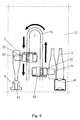
- FIG. 6 represents the stroke of the transfer and reversal device 18 and illustrates a bottle 2 in its position at the level of the conveyor belt 4 when it is gripped (bottle located on the side Figure right) and in its position before its introduction into a corresponding through hole 10 of a magazine 6 (left side of the figure).
- the bottles 2 are grasped at their body, which guarantees a more stable grip than in the case of a seizure at the level of their neck.
- this grip at their body also allows to limit the volume required during their reversal or reversal.
- the gripping device 17 removes, after setting the links 26 in motion to synchronize with the conveyor belt 4, a batch of bottles 2 moving with said conveyor belt 4, the escamote by the movement of the links 26, reverses them or reverses through the longitudinal arm forming the transfer and reversal device 18 to deposit them in a magazine 6. Simultaneously with this deposit, the gripper 17 takes a batch of bottles 2 cleaned in a store 6 and returns them through the longitudinal arm 18 to deposit them on the conveying belt 4 in motion, after having given it the linear speed of the conveyor belt 4, by rotation of the rods 26. Meanwhile, the tape 4 was not stopped, she continued to move at a constant speed.
- the cleaning machine it is therefore possible to transfer bottles 2 to be cleaned and cleaned between magazines moving in a sequential movement and a conveying belt 4 moving at a continuous speed, and conversely, all by guaranteeing a continuous flow upstream and downstream of the cleaning machine 1.
- the drive of the longitudinal arm 18 forming the transfer and reversal device 18 can be realized, for example, by means of a reversible motor connected to a pinion and end stops and controlled by the PLC. sequence sequencing.
- FIG. 5 represents the position of the support bar 22 during the setting of the bottles 2 to be cleaned and the deposition of the treated bottles on the conveyor belt 4.
- the links 26 are perpendicular to the conveyor belt 4 and have just made a pivoting movement between an eclipsed position corresponding to the return of the support bar 22 in the direction of the conveyor belt 4.
- the eclipsed position of the support bar 22 is not shown in the accompanying figures. It corresponds to a position in which the rods 26 are oriented towards the spacing device 8 of the bottles 2 (to the left in Figure 5).
- the actuator driving the angular displacement of the rods 26 may be a reversible stepper motor controlled by a programmable sequencing controller or by means of a displacement sequencing cam device.
- the support bar 22 can have two sets 24 and 24 'of clamps 25 and 25' respectively making the capture, on the conveyor belt 4, of the bottles 2 to be cleaned for their transfer.
- each of said sets 24 and 24 'of grippers 25 and 25' being constituted by a number of tongs 25 and 25 'equal to the number of bottles 2 which can be arranged in a magazine 6, said tongs 25 and 25' having a spacing relative to each other corresponding to the spacing between the bottles 2 in the magazines 6 and to that of the bottles as realized by the spacing device 8, and the two sets 24 and 24 'of clamps 25 and 25' being actuated in an inverted manner by an actuating device, so that the opening
- Figure 5 wherein the support bar 22 is in the setting position of the bottles 2 to clean and deposit cleaned bottles, highlights the closed or gripping position of the clamps 25 and the open position or deposition of the tongs 25 '.
- the clamps 25 are placed in the open position to deposit the bottles 2 to clean and, in reverse, the clamps 25 'are placed in the closed position to seize the bottles 2 cleaned.
- the actuation of the clamps may be of the known type and may be, for example, in the form of one or more cams associated with stops. These can detect the two useful positions of the simultaneous loading and unloading means 7 batches of bottles 2, namely the position above the conveyor belt 4 for taking the bottles 2 to clean and the deposit of the bottles 2 cleaned and the position above the frame guide 9 for depositing the bottles 2 to be cleaned and taking bottles 2 cleaned.
- the actuating device of the clamps 25 and 25 ' can also be in the form of an electromagnet whose core is connected to a control rod opening and closing of the clamps by means of bent levers or the like.
- the cleaning machine according to the invention is more particularly intended for cleaning glass bottles 2.
- the clamps 25 and 25 ' may be provided with an elastically deformable coating.
- the spacing device 8 of the bottles 2 can be made, for example, in the form of a worm screw, the pitch of the screw corresponding to the desired spacing between the bottles 2 in order to take them by the gripping device 17 of the bottles 2.
- At least one cleaning fluid recovery tank, washing, rinsing and / or disinfecting bottles can be provided under the guide frame 9.
- the guiding frame 9 can be further provided, on the one hand, with a first means for detecting the presence of the bottles 2 extending at the store 6 receiving the bottles 2 to be cleaned, forming a presence detector for a set of bottles 2 deposited and, secondly, between the position of the magazine 6 carrying the bottles 2 cleaned to transfer to the conveyor belt 4 and the retracted extreme position of the previous store extending adjacent said conveyor belt 4, a second bottle presence detecting means 2 forming a safety means and automatic stop of the cleaning machine 1.
- the first detection means can be realized in the form of several sensors in series, namely as many sensors as through holes 10 made in a magazine 6, each of said sensors that can be arranged in the path of a bottle 2 being placed in a magazine 6.
- This detection means can be connected to a programmable controller for managing the nozzles 20.
- a programmable controller for managing the nozzles 20.
- the second detection means can, for its part, be made in the form of a safety switch triggered by the contact of a bottle 2.
- the cleaning machine 1 can be connected, via the conveying belt 4, upstream of the gripping zone P, to an empty bottle loading means 2 and , downstream of the deposition zone P, to a filling machine 3 of said bottles 2, so as to provide a continuous filling installation 1 'of bottles 2.
- a capping machine 5 bottles 2 full it - even connected to a packaging or storage device, can be connected to the filling machine 3 of said bottles 2.
- the continuous filling plant 3, shown in FIG. 1, is in the form of a wheel supporting the bottles 2 at the level of the conveyor belt 4 with a view to filling them, and the same applies to the capping machine 5.
- the cleaning machine according to the invention is not limited to this type of filling installation.
- the capacity of the continuous filling installation 1 'of bottles 2 is limited by the cleaning capacity of the cleaning machine 1 integrated in said installation because the cleaning is an operation requiring many steps.
- the filling capacity of the continuous filling plant of the bottles 2 is increased.
Landscapes
- Engineering & Computer Science (AREA)
- Mechanical Engineering (AREA)
- Cleaning In General (AREA)
Applications Claiming Priority (1)
| Application Number | Priority Date | Filing Date | Title |
|---|---|---|---|
| FR0509281A FR2890579B1 (fr) | 2005-09-12 | 2005-09-12 | Machine de nettoyage de bouteilles |
Publications (2)
| Publication Number | Publication Date |
|---|---|
| EP1762308A2 true EP1762308A2 (de) | 2007-03-14 |
| EP1762308A3 EP1762308A3 (de) | 2008-04-09 |
Family
ID=36371054
Family Applications (1)
| Application Number | Title | Priority Date | Filing Date |
|---|---|---|---|
| EP06360036A Withdrawn EP1762308A3 (de) | 2005-09-12 | 2006-08-10 | Flaschenreinigungsvorrichtung |
Country Status (2)
| Country | Link |
|---|---|
| EP (1) | EP1762308A3 (de) |
| FR (1) | FR2890579B1 (de) |
Cited By (6)
| Publication number | Priority date | Publication date | Assignee | Title |
|---|---|---|---|---|
| CN106964621A (zh) * | 2017-03-30 | 2017-07-21 | 和县华安玻璃制品有限公司 | 一种玻璃瓶喷淋清洗室 |
| CN110449429A (zh) * | 2019-07-26 | 2019-11-15 | 青岛元信检测技术有限公司 | 一种离心管批量清洗装置 |
| CN111874589A (zh) * | 2020-08-04 | 2020-11-03 | 范林玲 | 一种一体式玻璃瓶自动化生产设备 |
| CN113951313A (zh) * | 2021-10-26 | 2022-01-21 | 内蒙古绿色大地农牧业有限公司 | 一种高效自动化的冷冻牛羊肉解冻装置 |
| CN115382870A (zh) * | 2022-07-14 | 2022-11-25 | 苏州新丽蒂化妆品有限公司 | 一种化妆品储存瓶的清洗系统 |
| CN119303876A (zh) * | 2024-12-17 | 2025-01-14 | 靖江佳佳精密机械科技有限公司 | 一种轻型发动机凸轮轴齿轮清洗装置 |
Citations (5)
| Publication number | Priority date | Publication date | Assignee | Title |
|---|---|---|---|---|
| GB293324A (en) | 1927-07-01 | 1930-01-02 | Heinrich Rumpen | Improvements in and relating to the cleaning of bottles and the like |
| DE719735C (de) | 1935-12-10 | 1942-04-16 | Enzinger Union Werke Ag | Flaschenreinigungsmaschine |
| US2826207A (en) | 1955-07-01 | 1958-03-11 | Gerber Prod | Glass jar washing machine |
| US3064663A (en) | 1961-11-22 | 1962-11-20 | Burgermeister Brewing Corp | Bottle rinser |
| FR2417469A1 (fr) | 1978-02-16 | 1979-09-14 | Hustache Jacques | Machine pour le rincage des bouteilles a la chaine |
-
2005
- 2005-09-12 FR FR0509281A patent/FR2890579B1/fr not_active Expired - Fee Related
-
2006
- 2006-08-10 EP EP06360036A patent/EP1762308A3/de not_active Withdrawn
Patent Citations (5)
| Publication number | Priority date | Publication date | Assignee | Title |
|---|---|---|---|---|
| GB293324A (en) | 1927-07-01 | 1930-01-02 | Heinrich Rumpen | Improvements in and relating to the cleaning of bottles and the like |
| DE719735C (de) | 1935-12-10 | 1942-04-16 | Enzinger Union Werke Ag | Flaschenreinigungsmaschine |
| US2826207A (en) | 1955-07-01 | 1958-03-11 | Gerber Prod | Glass jar washing machine |
| US3064663A (en) | 1961-11-22 | 1962-11-20 | Burgermeister Brewing Corp | Bottle rinser |
| FR2417469A1 (fr) | 1978-02-16 | 1979-09-14 | Hustache Jacques | Machine pour le rincage des bouteilles a la chaine |
Cited By (10)
| Publication number | Priority date | Publication date | Assignee | Title |
|---|---|---|---|---|
| CN106964621A (zh) * | 2017-03-30 | 2017-07-21 | 和县华安玻璃制品有限公司 | 一种玻璃瓶喷淋清洗室 |
| CN106964621B (zh) * | 2017-03-30 | 2019-02-15 | 和县华安玻璃制品有限公司 | 一种玻璃瓶喷淋清洗室 |
| CN110449429A (zh) * | 2019-07-26 | 2019-11-15 | 青岛元信检测技术有限公司 | 一种离心管批量清洗装置 |
| CN111874589A (zh) * | 2020-08-04 | 2020-11-03 | 范林玲 | 一种一体式玻璃瓶自动化生产设备 |
| CN111874589B (zh) * | 2020-08-04 | 2021-04-16 | 南通鑫德医药包装材料有限公司 | 一种一体式玻璃瓶自动化生产设备 |
| CN113951313A (zh) * | 2021-10-26 | 2022-01-21 | 内蒙古绿色大地农牧业有限公司 | 一种高效自动化的冷冻牛羊肉解冻装置 |
| CN113951313B (zh) * | 2021-10-26 | 2024-04-02 | 内蒙古绿色大地农牧业有限公司 | 一种高效自动化的冷冻牛羊肉解冻装置 |
| CN115382870A (zh) * | 2022-07-14 | 2022-11-25 | 苏州新丽蒂化妆品有限公司 | 一种化妆品储存瓶的清洗系统 |
| CN115382870B (zh) * | 2022-07-14 | 2023-09-01 | 上海上水和肌生物科技有限公司 | 一种化妆品储存瓶的清洗系统 |
| CN119303876A (zh) * | 2024-12-17 | 2025-01-14 | 靖江佳佳精密机械科技有限公司 | 一种轻型发动机凸轮轴齿轮清洗装置 |
Also Published As
| Publication number | Publication date |
|---|---|
| FR2890579A1 (fr) | 2007-03-16 |
| FR2890579B1 (fr) | 2008-05-30 |
| EP1762308A3 (de) | 2008-04-09 |
Similar Documents
| Publication | Publication Date | Title |
|---|---|---|
| EP3802377B1 (de) | Überführen von produkten durch einfassing aus oder zu einem speicherbereich | |
| CA3058100A1 (fr) | Transfert multilignes de produits | |
| FR2480234A1 (fr) | Appareil pour appliquer un tube de matiere plastique sur au moins deux recipients, et procede de fabrication d'un emballage | |
| EP3630615A1 (de) | Anlage zur herstellung von behältern mittels thermoformen | |
| EP0516563A1 (de) | Waschverfahren und Desinfektionsverfahren für Schuhe und Vorrichtung zur Durchführung des Verfahrens | |
| BE898468A (fr) | Procédé en vue d'extraire des bonbons glacés de poches de congélation dans une machine à congeler les bonbons glacés et dispositif d'extraction pour la mise en oeuvre de ce procédé. | |
| EP1762308A2 (de) | Flaschenreinigungsvorrichtung | |
| EP2051918B1 (de) | Vorrichtung zum umdrehen von behältern | |
| EP0033670B1 (de) | Verfahren und Vorrichtung zum Ausformen von Weichkäse | |
| WO2020064860A1 (fr) | Dispositif et procede de transfert de produits | |
| FR2765191A1 (fr) | Procede et machine de collage automatique d'un film plastique thermoretractable sur le fond d'une caisse ouverte | |
| FR2605592A1 (fr) | Procede d'encaissage de produits en sachets souples se presentant en vrac et en continu, et dispositif mettant en oeuvre ledit procede | |
| EP4079662A1 (de) | System zum be- und entladen von platten in einer maschine, die behälter bearbeitet | |
| EP0334769B1 (de) | Vorrichtung zum Be- und Entladen von in Schichten angeordneten Gegenständen | |
| EP4074633A1 (de) | System zur handhabung von platten in einer maschine, die behälter bearbeitet | |
| EP3738910B1 (de) | Produktbegleitvorrichtung, verpackungsanlage und entleerungsverfahren | |
| EP0113063B1 (de) | Verfahren und Vorrichtung zum Manipulieren von ineinandergreifenden Gussrohren zum Umsetzen von Paargruppen von Rohren in unpaarige Rohrgruppen | |
| EP0221001A1 (de) | Anlage und Verfahren zum automatischen Einsetzen von Kapseln in auf einem Gitter angeordneten elastischen Klemmen | |
| EP1300224B1 (de) | Maschine für das Fertigstellen von geklebten Korken | |
| EP0097679B1 (de) | Verfahren und vorrichtung zum entfernen einer haltestange von einer elektrode | |
| EP0060786B1 (de) | Verfahren und Vorrichtung zum Formen und Bündeln einer Anzahl von Gegenständen | |
| FR2612487A1 (fr) | Procede d'encaissage en continu et suivant des couches superposees, d'objets tels que par exemple des recipients, et machine comportant application de ce procede | |
| FR2508423A1 (fr) | Dispositif pour la manipulation de boites, notamment de boites de conserves | |
| FR2598336A1 (fr) | Manipulateur pour l'alimentation automatique des machines pour la centrifugation des bobines de fil | |
| FR2614272A1 (fr) | Procede d'elimination automatique d'un groupe d'objets a traiter dont au moins l'un est manquant ou defectueux, appareil pour l'execution de ce procede et machine de conditionnement de recipients equipee de cet appareil. |
Legal Events
| Date | Code | Title | Description |
|---|---|---|---|
| PUAI | Public reference made under article 153(3) epc to a published international application that has entered the european phase |
Free format text: ORIGINAL CODE: 0009012 |
|
| AK | Designated contracting states |
Kind code of ref document: A2 Designated state(s): AT BE BG CH CY CZ DE DK EE ES FI FR GB GR HU IE IS IT LI LT LU LV MC NL PL PT RO SE SI SK TR |
|
| AX | Request for extension of the european patent |
Extension state: AL BA HR MK YU |
|
| PUAL | Search report despatched |
Free format text: ORIGINAL CODE: 0009013 |
|
| AK | Designated contracting states |
Kind code of ref document: A3 Designated state(s): AT BE BG CH CY CZ DE DK EE ES FI FR GB GR HU IE IS IT LI LT LU LV MC NL PL PT RO SE SI SK TR |
|
| AX | Request for extension of the european patent |
Extension state: AL BA HR MK RS |
|
| 17P | Request for examination filed |
Effective date: 20080924 |
|
| AKX | Designation fees paid |
Designated state(s): AT BE BG CH CY CZ DE DK EE ES FI FR GB GR HU IE IS IT LI LT LU LV MC NL PL PT RO SE SI SK TR |
|
| 17Q | First examination report despatched |
Effective date: 20081223 |
|
| STAA | Information on the status of an ep patent application or granted ep patent |
Free format text: STATUS: THE APPLICATION IS DEEMED TO BE WITHDRAWN |
|
| 18D | Application deemed to be withdrawn |
Effective date: 20130301 |