EP4074633A1 - System zur handhabung von platten in einer maschine, die behälter bearbeitet - Google Patents
System zur handhabung von platten in einer maschine, die behälter bearbeitet Download PDFInfo
- Publication number
- EP4074633A1 EP4074633A1 EP22168657.9A EP22168657A EP4074633A1 EP 4074633 A1 EP4074633 A1 EP 4074633A1 EP 22168657 A EP22168657 A EP 22168657A EP 4074633 A1 EP4074633 A1 EP 4074633A1
- Authority
- EP
- European Patent Office
- Prior art keywords
- plates
- section
- support
- plate
- return
- Prior art date
- Legal status (The legal status is an assumption and is not a legal conclusion. Google has not performed a legal analysis and makes no representation as to the accuracy of the status listed.)
- Withdrawn
Links
- 238000012545 processing Methods 0.000 title claims abstract description 10
- 238000006073 displacement reaction Methods 0.000 claims abstract description 34
- 235000013305 food Nutrition 0.000 claims description 14
- 238000012546 transfer Methods 0.000 description 30
- 238000000034 method Methods 0.000 description 10
- 230000008569 process Effects 0.000 description 8
- 230000007246 mechanism Effects 0.000 description 6
- 230000000694 effects Effects 0.000 description 4
- 238000009434 installation Methods 0.000 description 4
- 238000004519 manufacturing process Methods 0.000 description 4
- 235000013365 dairy product Nutrition 0.000 description 3
- 230000003670 easy-to-clean Effects 0.000 description 3
- 230000005484 gravity Effects 0.000 description 3
- 238000013519 translation Methods 0.000 description 3
- 230000004323 axial length Effects 0.000 description 2
- 239000005428 food component Substances 0.000 description 2
- 235000012041 food component Nutrition 0.000 description 2
- 238000002372 labelling Methods 0.000 description 2
- 238000012423 maintenance Methods 0.000 description 2
- 229910001092 metal group alloy Inorganic materials 0.000 description 2
- 210000000056 organ Anatomy 0.000 description 2
- 239000010935 stainless steel Substances 0.000 description 2
- 229910001220 stainless steel Inorganic materials 0.000 description 2
- 238000004659 sterilization and disinfection Methods 0.000 description 2
- 206010035148 Plague Diseases 0.000 description 1
- 239000004743 Polypropylene Substances 0.000 description 1
- 238000009825 accumulation Methods 0.000 description 1
- 239000000969 carrier Substances 0.000 description 1
- 238000010276 construction Methods 0.000 description 1
- 238000013461 design Methods 0.000 description 1
- 235000015243 ice cream Nutrition 0.000 description 1
- 230000006872 improvement Effects 0.000 description 1
- 238000003780 insertion Methods 0.000 description 1
- 230000037431 insertion Effects 0.000 description 1
- 230000003993 interaction Effects 0.000 description 1
- 238000002955 isolation Methods 0.000 description 1
- 238000003754 machining Methods 0.000 description 1
- 239000000463 material Substances 0.000 description 1
- 230000005226 mechanical processes and functions Effects 0.000 description 1
- 238000012544 monitoring process Methods 0.000 description 1
- 238000010137 moulding (plastic) Methods 0.000 description 1
- 235000011837 pasties Nutrition 0.000 description 1
- 239000004033 plastic Substances 0.000 description 1
- 229920003023 plastic Polymers 0.000 description 1
- 229920000515 polycarbonate Polymers 0.000 description 1
- 239000004417 polycarbonate Substances 0.000 description 1
- 229920000379 polypropylene carbonate Polymers 0.000 description 1
- 230000000750 progressive effect Effects 0.000 description 1
- 230000000717 retained effect Effects 0.000 description 1
- 239000000725 suspension Substances 0.000 description 1
- 235000020357 syrup Nutrition 0.000 description 1
- 239000006188 syrup Substances 0.000 description 1
- 238000012360 testing method Methods 0.000 description 1
- 238000012549 training Methods 0.000 description 1
- 239000002699 waste material Substances 0.000 description 1
Images




Classifications
-
- B—PERFORMING OPERATIONS; TRANSPORTING
- B65—CONVEYING; PACKING; STORING; HANDLING THIN OR FILAMENTARY MATERIAL
- B65G—TRANSPORT OR STORAGE DEVICES, e.g. CONVEYORS FOR LOADING OR TIPPING, SHOP CONVEYOR SYSTEMS OR PNEUMATIC TUBE CONVEYORS
- B65G35/00—Mechanical conveyors not otherwise provided for
- B65G35/06—Mechanical conveyors not otherwise provided for comprising a load-carrier moving along a path, e.g. a closed path, and adapted to be engaged by any one of a series of traction elements spaced along the path
-
- B—PERFORMING OPERATIONS; TRANSPORTING
- B65—CONVEYING; PACKING; STORING; HANDLING THIN OR FILAMENTARY MATERIAL
- B65B—MACHINES, APPARATUS OR DEVICES FOR, OR METHODS OF, PACKAGING ARTICLES OR MATERIALS; UNPACKING
- B65B43/00—Forming, feeding, opening or setting-up containers or receptacles in association with packaging
- B65B43/42—Feeding or positioning bags, boxes, or cartons in the distended, opened, or set-up state; Feeding preformed rigid containers, e.g. tins, capsules, glass tubes, glasses, to the packaging position; Locating containers or receptacles at the filling position; Supporting containers or receptacles during the filling operation
-
- B—PERFORMING OPERATIONS; TRANSPORTING
- B65—CONVEYING; PACKING; STORING; HANDLING THIN OR FILAMENTARY MATERIAL
- B65B—MACHINES, APPARATUS OR DEVICES FOR, OR METHODS OF, PACKAGING ARTICLES OR MATERIALS; UNPACKING
- B65B43/00—Forming, feeding, opening or setting-up containers or receptacles in association with packaging
- B65B43/42—Feeding or positioning bags, boxes, or cartons in the distended, opened, or set-up state; Feeding preformed rigid containers, e.g. tins, capsules, glass tubes, glasses, to the packaging position; Locating containers or receptacles at the filling position; Supporting containers or receptacles during the filling operation
- B65B43/54—Means for supporting containers or receptacles during the filling operation
- B65B43/60—Means for supporting containers or receptacles during the filling operation rotatable
-
- B—PERFORMING OPERATIONS; TRANSPORTING
- B65—CONVEYING; PACKING; STORING; HANDLING THIN OR FILAMENTARY MATERIAL
- B65G—TRANSPORT OR STORAGE DEVICES, e.g. CONVEYORS FOR LOADING OR TIPPING, SHOP CONVEYOR SYSTEMS OR PNEUMATIC TUBE CONVEYORS
- B65G19/00—Conveyors comprising an impeller or a series of impellers carried by an endless traction element and arranged to move articles or materials over a supporting surface or underlying material, e.g. endless scraper conveyors
- B65G19/02—Conveyors comprising an impeller or a series of impellers carried by an endless traction element and arranged to move articles or materials over a supporting surface or underlying material, e.g. endless scraper conveyors for articles, e.g. for containers
-
- B—PERFORMING OPERATIONS; TRANSPORTING
- B65—CONVEYING; PACKING; STORING; HANDLING THIN OR FILAMENTARY MATERIAL
- B65G—TRANSPORT OR STORAGE DEVICES, e.g. CONVEYORS FOR LOADING OR TIPPING, SHOP CONVEYOR SYSTEMS OR PNEUMATIC TUBE CONVEYORS
- B65G35/00—Mechanical conveyors not otherwise provided for
- B65G35/06—Mechanical conveyors not otherwise provided for comprising a load-carrier moving along a path, e.g. a closed path, and adapted to be engaged by any one of a series of traction elements spaced along the path
- B65G35/063—Mechanical conveyors not otherwise provided for comprising a load-carrier moving along a path, e.g. a closed path, and adapted to be engaged by any one of a series of traction elements spaced along the path the traction element being a rotating bar or tube
-
- B—PERFORMING OPERATIONS; TRANSPORTING
- B65—CONVEYING; PACKING; STORING; HANDLING THIN OR FILAMENTARY MATERIAL
- B65G—TRANSPORT OR STORAGE DEVICES, e.g. CONVEYORS FOR LOADING OR TIPPING, SHOP CONVEYOR SYSTEMS OR PNEUMATIC TUBE CONVEYORS
- B65G35/00—Mechanical conveyors not otherwise provided for
- B65G35/06—Mechanical conveyors not otherwise provided for comprising a load-carrier moving along a path, e.g. a closed path, and adapted to be engaged by any one of a series of traction elements spaced along the path
- B65G35/063—Mechanical conveyors not otherwise provided for comprising a load-carrier moving along a path, e.g. a closed path, and adapted to be engaged by any one of a series of traction elements spaced along the path the traction element being a rotating bar or tube
- B65G35/066—Mechanical conveyors not otherwise provided for comprising a load-carrier moving along a path, e.g. a closed path, and adapted to be engaged by any one of a series of traction elements spaced along the path the traction element being a rotating bar or tube the bar or the tube being provided with a helical or annular channel
-
- B—PERFORMING OPERATIONS; TRANSPORTING
- B67—OPENING, CLOSING OR CLEANING BOTTLES, JARS OR SIMILAR CONTAINERS; LIQUID HANDLING
- B67C—CLEANING, FILLING WITH LIQUIDS OR SEMILIQUIDS, OR EMPTYING, OF BOTTLES, JARS, CANS, CASKS, BARRELS, OR SIMILAR CONTAINERS, NOT OTHERWISE PROVIDED FOR; FUNNELS
- B67C3/00—Bottling liquids or semiliquids; Filling jars or cans with liquids or semiliquids using bottling or like apparatus; Filling casks or barrels with liquids or semiliquids
- B67C3/02—Bottling liquids or semiliquids; Filling jars or cans with liquids or semiliquids using bottling or like apparatus
- B67C3/22—Details
- B67C3/225—Means for filling simultaneously, e.g. in a rotary filling apparatus or multiple rows of containers
-
- B—PERFORMING OPERATIONS; TRANSPORTING
- B67—OPENING, CLOSING OR CLEANING BOTTLES, JARS OR SIMILAR CONTAINERS; LIQUID HANDLING
- B67C—CLEANING, FILLING WITH LIQUIDS OR SEMILIQUIDS, OR EMPTYING, OF BOTTLES, JARS, CANS, CASKS, BARRELS, OR SIMILAR CONTAINERS, NOT OTHERWISE PROVIDED FOR; FUNNELS
- B67C3/00—Bottling liquids or semiliquids; Filling jars or cans with liquids or semiliquids using bottling or like apparatus; Filling casks or barrels with liquids or semiliquids
- B67C3/02—Bottling liquids or semiliquids; Filling jars or cans with liquids or semiliquids using bottling or like apparatus
- B67C3/22—Details
- B67C3/24—Devices for supporting or handling bottles
- B67C3/242—Devices for supporting or handling bottles engaging with bottle necks
-
- B—PERFORMING OPERATIONS; TRANSPORTING
- B67—OPENING, CLOSING OR CLEANING BOTTLES, JARS OR SIMILAR CONTAINERS; LIQUID HANDLING
- B67C—CLEANING, FILLING WITH LIQUIDS OR SEMILIQUIDS, OR EMPTYING, OF BOTTLES, JARS, CANS, CASKS, BARRELS, OR SIMILAR CONTAINERS, NOT OTHERWISE PROVIDED FOR; FUNNELS
- B67C7/00—Concurrent cleaning, filling, and closing of bottles; Processes or devices for at least two of these operations
- B67C7/0006—Conveying; Synchronising
- B67C7/0026—Conveying; Synchronising the containers travelling along a linear path
- B67C7/0033—Conveying; Synchronising the containers travelling along a linear path the operation being performed batch-wise
-
- B—PERFORMING OPERATIONS; TRANSPORTING
- B65—CONVEYING; PACKING; STORING; HANDLING THIN OR FILAMENTARY MATERIAL
- B65G—TRANSPORT OR STORAGE DEVICES, e.g. CONVEYORS FOR LOADING OR TIPPING, SHOP CONVEYOR SYSTEMS OR PNEUMATIC TUBE CONVEYORS
- B65G2201/00—Indexing codes relating to handling devices, e.g. conveyors, characterised by the type of product or load being conveyed or handled
- B65G2201/02—Articles
- B65G2201/0235—Containers
-
- B—PERFORMING OPERATIONS; TRANSPORTING
- B65—CONVEYING; PACKING; STORING; HANDLING THIN OR FILAMENTARY MATERIAL
- B65G—TRANSPORT OR STORAGE DEVICES, e.g. CONVEYORS FOR LOADING OR TIPPING, SHOP CONVEYOR SYSTEMS OR PNEUMATIC TUBE CONVEYORS
- B65G2201/00—Indexing codes relating to handling devices, e.g. conveyors, characterised by the type of product or load being conveyed or handled
- B65G2201/02—Articles
- B65G2201/0235—Containers
- B65G2201/0244—Bottles
- B65G2201/0247—Suspended bottles
Definitions
- the present invention relates to handling systems in a machine processing food product containers. These machines can also be called equipment or production lines.
- These machines/equipment use supports, for example plates, to support the containers during the operations carried out in the machine.
- This type of support plate is also used in machines or installations which treat containers of non-food products to which the present invention can be applied.
- the return circuit of the support plates occupies an important place in such an installation, whether the return occurs from below, or from above, or at the same level, with respect to the working section.
- the plates traverse the return circuit, in a posture parallel to the posture of the working circuit, in an orientation identical to the working circuit or after undergoing a 180 degree reversal.
- the return path of the plates occupies a reduced space.
- the overall compactness of the machine/line can be improved.
- the footprint of the machine can be reduced.
- this arrangement of the handling system facilitates access to the various elements and organs of the production line, in particular for monitoring and maintenance purposes.
- first and second sections TC1 and TC2 are substantially of the same length and straight, which forms a simple and economically relevant construction.
- the support plate undergoes a rotation around the reference longitudinal axis X1 by an angle ⁇ (90° in a typical case) then the plate traverses the return section substantially keeping this orientation, after which the support plate undergoes a rotation in the opposite direction around the axis longitudinal X1 by an angle - ⁇ .
- the plate is driven by a alone of its longitudinal edges, the opposite edge being only guided but not driven.
- the motorization eg displacement member
- the motorization is thus relatively simple and is located in the vicinity of the longitudinal axis X1 of the handling system.
- each of the support plates is driven close to the same longitudinal edge, the opposite longitudinal edge not being driven.
- the opposite longitudinal edge is free from any interaction, it simply hangs.
- the shape of the plates is defined by their two large dimensions which can be called length and width and by a substantially smaller dimension which can be called thickness.
- the plate orientation is said to be horizontal when the two major dimensions extend horizontally and the thickness extends vertically, and the plate orientation is said to be vertical when the thickness extends in a horizontal direction.
- stepper displacement member it is necessary to understand a mechanism allowing an advance of a predefined distance then a stop for a treatment at a fixed station.
- the second displacement member can be of the continuous type or of the discontinuous type.
- the first rotation station PR1 comprises a first rotating base 41
- the second rotation station PR2 comprises a second rotating base 42 and there is provided a fixed main guide support 40, disposed continuously along the first axial direction X1A between the first and second rotary bases.
- the first rotating base rotates the support plates towards the horizontal position, to engage them on the first section, while the second rotating base rotates the support plates towards the return orientation to engage them on the second section.
- a positive and continuous guide of the plates is provided from the first end E1 to the second end E2 on the first section TC1. It is noted here that the guidance on the second section (that of rapid return) can be lightened, or even a flexible guidance is sufficient, by suspension for example.
- the first rotation station and/or the second rotation station may/may be different from a rotary base, and be produced by cam effect with progressive rotation and advancement.
- each support plate comprises at least one notch to receive a finger of the first displacement member.
- two notches can preferably be provided in each support plate.
- the advance is preferably made by a pitch substantially equal to the length of the plate.
- notches can be provided per plate, for a quarter-length advance kinematics of the plate.
- the notch is through. This is easy to clean and prevents dirt from getting lodged in a blind hole.
- the notch is arranged on the edge of the plate. Such a form is easy to make, also easy to clean.
- the first displacement member comprises two degrees of freedom, namely a rotation around the axial direction X1 and an advancement along the axial direction X1.
- the first displacement member comprises a finger arranged at a distance from the axis X1 and configured to be received in a notch of the plate, the return of the finger being empty when the finger is not engaged.
- the first displacement member can be described as a “transfer shuttle”. According to the possible configurations, it can cause an advance of a quarter, a half or a whole axial length of the support plate.
- each support plate generally extends in a reference plane PR, with a generally rectangular shape, each support plate comprises two long sides, ie a long side forming a guide and maneuver border, another long side forming a free border.
- the two short sides can be straight or not.
- each support plate is preferably planar. This plate is then easy to manufacture from a cut blank. It is also an economical solution that minimizes machining rework.
- each support plate is made in one piece. This plate is then easy to wash, being devoid of an assembly joint.
- each support plate is made of stainless steel or of a food-compatible metal alloy. This favors lightness, durability and hygiene for support plates versus food contact.
- an upper face of the support plate is defined, and nothing protrudes from the upper face, except where appropriate centering studs arranged on the periphery of the housings. Note that the upper faces of the plates in the working section are flush with a working plane denoted PW.
- At least one groove is provided in the plate for holding the plate in particular when it is in the return orientation. This groove allows the plate to be held along the return circuit and prevents the plates from sliding down and/or falling.
- the groove is arranged on the bottom face, while the notches are arranged on the top face or on the edge.
- the groove does not retain small waste and remains clean.
- At least one out-of-plane projection is provided in the plate, or a rib, for holding the plate in particular when it is in the return orientation.
- an auxiliary guide support is provided to support the support plates, on the cantilever side, on the free edge side, in the first section.
- said auxiliary guide support is removable, in part or in whole. It is thus possible if necessary to remove the auxiliary guide support to have complete access to the handling systems or to one of the modules of the machine.
- said auxiliary guide support is carried by processing equipment of the machine, ie one or more of the process modules of which the line is dialed.
- processing equipment of the machine ie one or more of the process modules of which the line is dialed.
- the second mover is formed as a chain or loop belt conveyor. This type of solution is rustic and robust, and very reliable.
- motorized rollers can be provided as the second displacement member.
- the second displacement member can be formed as a loop belt conveyor with double teeth (one tooth inside for driving the belt and one tooth outside for driving the plates -belt support).
- the system is such that the number of plates in the first section TC1 is greater than twice the number of plates in the second section TC2. This minimizes the total number of plates; most plates are used on the working leg and very few plates are present on the return leg. Note that in a number of systems known from the prior art, the number of plates on the return is equal to the number of plates on the outward-to-work section.
- the system is such that the average speed on the second section TC2 is substantially higher, or even much higher, than the average speed on the first section TC1. This characteristic can also lead to minimizing the number of plates in the return section.
- the second displacement member can operate by momentum, with a speed pulse, and possibly an arrival brake.
- a return by gravity can be provided.
- the second mover may be formed as a high-pitch transfer shuttle, a multiple of PX.
- the handling system is such that at the rotation station PR1, a stop is formed for the vertical plates in return while waiting for the ad hoc position of the rotating base.
- This function can be performed by an erasable stop.
- a zone is formed for the accumulation of the plates in return, the surplus of plates on standby are stored at this place.
- the plates are adjacent in the first section TC1, a pushing operation is used. It then suffices to advance the first plate on the first section TC1, which simplifies the design of the transfer shuttle and which reduces its cost.
- the first displacement member namely the transfer shuttle, individually engages all the plates or almost all the plates on the first section TC1. In this case the plates do not push each other,
- the plates are spaced apart in the first section TC1, with operation by transfer/advancement of a pitch slightly greater than the length of the plate. A small functional clearance is thus provided which avoids friction between the plates.
- it may be superfluous to use advance indexing at workstations; the progress controlled by the first displacement member is sufficient to ensure the precision required for the arrival of the plate; only a work index may be necessary depending on the operation.
- the plates comprise 8 slots, or 4 or 6 or any other value.
- the invention works regardless of the number of housings provided in the plate.
- the plates comprise from 1 to 4 rows of housings in the transverse direction Y, and in each row there can be found from 1 to 4 housings arranged along the longitudinal axis.
- the housings for the containers occupy a central zone with respect to each support plate.
- the containers e.g. pots or bottles, extend downwards from the reference plane of the support plate, between the two longitudinal edges of the support plate.
- the plates have a longitudinal length PX of between 250mm and 680mm, preferably of between 360mm and 520mm, and even more preferably of between 400mm and 480mm
- the plates have a thickness comprised between 3 mm and 10 mm. According to a particular example, a thickness between 6 mm and 8 mm can be chosen.
- the plates can be made in two parts, namely a flat plate with the housings and a technical profile for the guiding and driving functions.
- the present invention also relates to a machine for treating jars or bottles of food product, comprising a handling system as described above.
- the process modules can come from above and below without be hampered by the plate supports.
- the figures 1 and 2 represent a machine processing food product containers. It can be dairy products, syrups, drinks of all kinds, even pasty or powdered products, without excluding ice cream and animal feed.
- the present invention applies in fact to any food product.
- these machines/equipment/lines make it possible to fill containers, for example jars or bottles, with one or more food products, for example a dairy product and/or food components, and to seal these containers. He marking, labeling and prior disinfection operations may also be optionally provided. However, any other operation is not excluded.
- figures 1 and 2 processing modules juxtaposed in the axial direction of the machine marked respectively 71, 72, 7i. The various processing modules or process modules are collectively identified by the reference 7.
- Supports are used, which will be called support plates, or even simply plates, to support the containers during the operations carried out in the machine.
- the handling system comprises a first section TC1, called work.
- the handling system comprises a second section TC2, called a rapid return section.
- first section TC1 and the second section TC2 together form, with the rotation stations at the ends described below, a closed circuit, that is to say a looped circuit in normal operation.
- each support plate 1 is loaded with empty containers, and at another point, downstream, the filled containers are removed from the support plate 1.
- Each support plate 1 comprises one or more housings 18, each housing 18 being capable of receiving a container.
- the container is received from above, in which case it is by the effect of gravity that an upper edge 58 of the container bears on an edge of the housing.
- the housing may be formed as an orifice.
- the container is typically a pot 5 with a flange 58 wider than its body.
- the container can be received by lateral insertion, a neck of the container is housed in a housing having a mouth and a strait. After passing the neck of the container through the strait, the container remains retained in a hole of dimension corresponding to the dimension of the collar.
- the container is typically a bottle with a neck and a neck.
- the number of slots can be 4 or 8. However, the number of slots can be any, from 2 to 16.
- the number of rows along the transverse axis Y can be 1, 2, or even four rows; on each of the rows one can have from 1 to four dwellings.
- the handling system comprises a first end E1 and a second end E2.
- first rotation station PR1 arranged at the first end E1, configured to rotate the support plates towards the horizontal position, to engage them on the first section TC1.
- second rotation station PR2 arranged at the second end E2, configured to pivot the support plates towards the return orientation to engage them on the second section TC2.
- the longitudinal work axis (ie of the machine) is denoted X ; a longitudinal reference axis of the handling system denoted X1 is defined.
- the transverse axis of the machine is denoted Y the local vertical axis is denoted Z.
- the entire handling system is supported by a general support frame marked 6 (represented only generically in Figures 1, 2 and 17 ).
- the X1 axis is located on the outside of the machine, ie the plates 1 in the TC1 section are between the X1 axis and the process modules 7.
- the X1 axis is located on the inside of the machine, i.e. the X1 axis is located between the plates 1 on the first section TC1 and the process modules 7.
- each support plate 1 extends generally in a reference plane PR, with a generally rectangular shape.
- Each support plate comprises two short sides marked 13 and 14 respectively, parallel to the Y direction of the machine.
- Each support plate has two long sides parallel to the longitudinal direction X of the machine, namely a first long side 11 forming a guide and maneuver edge, and another long side 12 forming a free edge.
- the longitudinal length denoted PX is here between 400 mm and 480 mm. However, more generally, the length PX can be between 250mm and 680mm, or else between 360mm and 520mm. Note that a small longitudinal play can be provided between the plates.
- the width of the plate noted LW here between 250 mm and 350 mm. However, more generally, the width LW can be between 200 mm and 500 mm.
- Each support plate is made from a single piece. Each support plate is flat.
- the thickness of an EPP plate can typically be between 3 and 10 mm. Typically, we start from a blank of constant thickness and we arrange the notches and grooves there, so this will be discussed later. According to one example, the EPP thickness can be 8 mm. According to another example, the EPP thickness can be between 6 mm and 8 mm.
- Each support plate 1 comprises an upper face 1A and a lower face 1B.
- Each support plate 1 can be made of stainless steel or of a food-compatible metal alloy. However, a material of the food-compatible hard plastic type such as polypropylene or polycarbonate could also be suitable.
- the support plates In the first section TC1, the support plates circulate in a horizontal position in a first axial direction X1A.
- the plates In the various illustrations, the plates are adjacent to each other in the first section. However, it is not excluded that they are slightly spaced from each other.
- the support plates advance in a second axial direction X1B opposite to the first axial direction.
- the support plates circulate in a posture or orientation which is different from the horizontal position.
- the term "return orientation" is used for this posture. Said return orientation is vertical in the example shown. In a variant not shown, the return orientation can be angularly distant from the vertical by less than 30 degrees, that is to say not very far from the vertical position.
- the first long side 11 forms a guide and maneuver border.
- the guidance and drive functions are located in the vicinity of this large side.
- the edge corresponding to this long side is received in one or more grooves for guiding and receiving guides and rotary bases as will be described later.
- the opposite edge 12 is only guided but not driven.
- the motorization is thus relatively simple and is located in the vicinity of the longitudinal axis X1 of the handling system.
- the support plate is engaged and driven in a substantially cantilevered configuration, ie in the zone of a large side 11 close to the axis X1.
- the area located below the support plate and the large side 12, opposite the drive side, remains devoid of drive means.
- the guide allows such training from one large side reliably and precisely.
- the area below the support plate is dedicated to receiving jars and/or bottles which are held by the support plates.
- the opposite long edge 12 can be supported by an auxiliary guide 44.
- This auxiliary guide can be continuous or discontinuous; as illustrated figure 9 , this auxiliary guide 44 can be carried by an arm 70 integral with one of the aforementioned process modules 7i.
- This auxiliary guide 44 is preferably removable.
- housings provided in the support plate can be round or square depending on the shape of the pots to be treated.
- Each support plate comprises at least one notch 16 to receive a finger of the first displacement member.
- the notch or notches 16 is (are) preferably through (s) on the thickness of the plate. This is easy to clean and prevents dirt from coming in. lodge in a blind hole.
- each support plate comprises two notches.
- a projection 15 forming an out-of-plane projection, which serves to retain the plate in particular in its vertical orientation.
- a longitudinal groove marked 19 is used to hold the plate in which is housed a longitudinal rib 28, 29 provided in the means for guiding the plates.
- auxiliary notches marked 10 may be provided which may be used for indexing purposes on the processing stations.
- the plate may have a generally square shape instead of a rectangle.
- short sides are not necessarily straight, they can include a convex or concave drop.
- first member 2 for moving the support plates along the first axial direction X1A.
- first member 2 is of the stepper type.
- any type of displacement mechanism can be considered within the scope of the present invention.
- the first displacement member 2 comprises, in the example illustrated, a transfer bar 21 which generally extends along the axial direction and is pivotally mounted around the axis X1.
- the transfer bar 21 of the first displacement member 2 comprises a finger 26 at a distance from the axis X1 and configured to be received in a notch 16 of the plate, the empty return of the finger and of the transfer bar being carried out while the finger 26 is not engaged.
- the transfer bar 21 of the first displacement member 2 operates with two degrees of freedom, namely a rotation around X1 and an advancement in the axial direction.
- the rotation allows the engagement and disengagement of the finger 26 in a notch 16.
- the axial translation makes it possible to advance by a predetermined distance one or more plates on the first section.
- the predetermined distance coincides with the axial length of the plate, that is to say the pitch PX.
- the advance distance at each movement of the transfer bar can be PX/2.
- the advance distance at each movement of the transfer bar can be PX/4.
- the axial translation is carried out by a screw-nut or rack mechanism, it is generally possible to use an axial translation mechanism known per se.
- an axis shaft denoted 22 which can be fixed or secured to the transfer bar itself.
- the device also comprises a motor denoted M2, or a geared motor, which is placed in the vicinity of the axle shaft.
- An output pinion engages on a rack or a helical toothing to move the transfer bar 21 along the longitudinal direction X1, with rotation of the axis shaft 22 or not depending on the possible configurations.
- the transfer bar is equipped with a rear lever marked 25 integral with rigid rotation of the body of the transfer bar;
- the rear lever 25 is received in a slide connection 27 longitudinal.
- the rear lever 25 can thus slide along X1 in the slideway 27.
- a single-acting control cylinder noted M1 is provided as well as a return spring 45.
- the return spring has the effect of tilting the transfer bar around the axis X1 towards the disengaged position of the control finger 26, while conversely the actuation of the cylinder M1 has the effect of tilting the transfer bar in the opposite direction and of engaging the control finger in the notch 16.
- first displacement member 2 can be described as a “shuttle transfer ". Any other solution for causing at least one plate to advance over a predetermined distance can also be envisaged.
- the transfer shuttle simultaneously engages all the plates located on the working section TC1.
- the transfer bar 21 and the axis shaft 22 run almost the entire length of the handling system except where appropriate the ends.
- the plates do not push each other and are not necessarily adjacent, there may be a small gap forming running clearance. This also makes it possible to operate the machine under test with only a few plates.
- the transfer shuttle engages only the first plate located at the start of the first section and the plates push each other until the end of the first section.
- the axis shaft and the transfer bar are then much shorter, that is to say the order of magnitude corresponds to the length of a PX plate or a little more.
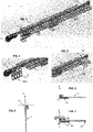
- the transfer shuttle can work from below as shown in figure 14 and 15 , as illustrated below.
- the transfer bar 21 is located below the upper face 1A of the plates in the working section, the zone located above the work surface marked PW is free of any element which may present a nuisance or a risk of pollution.
- the handling system comprises a second displacement member 3 configured to move the support plates in the second axial direction X1B in the second section TC2.
- the second displacement member is preferably of the continuous or discontinuous type.
- the second moving member comprises an endless belt marked 34.
- This belt is guided and driven by two grooved pulleys, including a leading pulley 32 driven by a motor M3 and a follower pulley 33 at the other end of the belt.
- the belt rubs against the underside 1B of the plates, in the return orientation posture, namely in the vertical position, to drive them from the second end E2 towards the first end E1.
- the belt is double-toothed: one toothing on the inside for driving the belt by the pulley and one toothing on the outside for driving the support plates by the belt.
- the second displacement member can be formed by a chain with articulated links mounted in a loop on two toothed sprockets at the ends.
- a first toothed pinion is driving, and the other is mounted on a support elastically returned by spring to tend to maintain sufficient tension on the chain at all times.
- Skids fixed on the outside of certain links of the loop chain can be provided to come to rest on the plates in their vertical posture and drive the plates.
- a working strand 34a is arranged in contact with the plates which are located on the second section while a return strand 34b is at a distance from the plates and is used for the empty return.
- the feed rate of the working side of the belt is relatively fast. In practice it is at least equal to the forward speed of the transfer bar in the opposite direction.
- the forward speed of the belt 34 can be at least equal to 500 mm per second.
- the motorization of the plates on the second section could be different from that illustrated, for example a system with impulse, return by gravity, or any other solution made possible by the fact that there is no work operation on the plates on this return leg.
- the motorization of the plates on the second section could be carried out by a large pitch transfer shuttle (a multiple of PX).
- the first rotation station PR1 comprises a first rotating base 41 on the side of the first end E1.
- the first rotating base pivots the support plates towards the horizontal position, to engage them on the first section TC1.
- the first rotary base may be formed as a member rotatably mounted around of an axis coinciding with X1 or close to the latter, this element being driven in angular position by a geared motor with two end-of-travel sensors or a stepper motor with an end-of-travel sensor.
- the first rotating base 41 is therefore movable between a first position suitable for receiving a support plate arriving on the second section in a return orientation and a second position suitable for placing a support plate in a horizontal position at the entrance to the first section.
- an erasable stop 49 which subordinates the entry of a vertical plate back into the rotating base 41 to a vertical reception position of this rotating base.
- the erasable stop 49 can be selectively controlled by a small actuator M4.
- the erasable stop can be a form integrated into the side of the rotating base 41, without requiring a specific command other than the rotation of the rotating base 41.
- the second rotation station PR2 On the side of the second end E2, the second rotation station PR2 comprises a second rotating base 42.
- the second rotating base rotates the support plates towards the return orientation to engage them on the second section TC2.
- the second rotating base can be formed as an element mounted for rotation around an axis coinciding with X1 or close to the latter, this element being controlled in angular position by a geared motor with two limit sensors or a stepper motor with a limit switch. If the way is clear, the second rotating base pivots the plate into the vertical position and inserts it immediately into the second return section TC2.
- Each of the rotating bases comprises a groove for receiving the longitudinal edge, ie the large side 11 forming a guide and maneuver edge.
- Both the first rotary base and the second rotary base include means for retaining the plates.
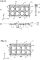
- the rotating bases comprise a housing forming a slide to receive this out-of-plane projection (Cf figure 11 ).
- each support plate 1 has a guide groove 19.
- the rotating bases comprise a projecting rib 29 on which bears inside the groove 19 provided in the plates. (see Figs 13 and 14 lower part).
- a fixed main guide support 40 arranged continuously along the first axial direction X1A, between the first and second rotating bases 41,42. The support is thus continuous for the plates from the first end E1 to the second end E2.
- the main guide support comprises a rib 28 which allows the longitudinal guidance of the plates, the rib 28 being received in the groove 19.
- the main guide support is formed as a profile with a generally constant section along X1.
- This section makes it possible, on the one hand, to guide the plates in a horizontal position which transit in the first section TC1, and on the other hand to guide the plates in a vertical position in the second section TC2 where they circulate in return.
- This type of system with support plates can also be used in machines or installations that treat containers of non-food products to which the present invention can be applied.
- the plates are moved sequentially from one station to another by the first moving member 2 described above.
- the plates are in the horizontal position, mark 1H in figures 15 and 16 .
- various operations are carried out at a fixed station, in the time interval between the forward movements of the transfer bar.
- metering nozzles marked 77 are provided, located at the location of one of the positions of the plate.
- the second rotating base 42 performs a rotation of each support plate 1 around the longitudinal reference axis X1 by an angle ⁇ (90° in a typical case). Following which, each plate traverses the return section substantially keeping this orientation.
- the plates are in the vertical position, mark 1V in figures 15 and 16 .
- the plaques are moved along the second section TC2 by the second displacement member 3 described above.
- the first rotating base 41 rotates the support plate which undergoes a rotation in the opposite direction around the longitudinal axis X1 by an angle - ⁇ , that is to say opposite to the angle applied by the second rotating base.
- the first section TC1 is completely occupied by the plates, while the second section TC2 comprises only a few plates, as this is visible from the figure 16 .
- the number of plates on the first section can be between ten and thirty depending on the configuration of the machine.
- the total number of plates necessary for the handling system and the process of the installation is minimized.
- the plates are made in two parts, namely on the one hand a flat plate denoted 1' with the housings 18 and on the other hand a technical profile 17 for the guiding and driving functions.
- the technical profile 17 for guiding and driving comprises a guide groove 190 whose functions are identical to the groove 19 previously described.
- the technical profile 17 for guiding and driving comprises two notches 160 arranged on the edge of the plate, side of the large side.
- the technical section 17 has a length PX identical to the longitudinal dimension of the plate PX.
- the flat plate 1' is obtained from a blank in which holes are made, so it is easy to make.
- the technical section 17 is fixed under the plate, ie fixed to the underside 1B of the plate 1'. None protrudes from the upper plane 1A of the plate.
- the technical profile 17 is obtained by plastic molding.
- a plate has been removed, another is made transparent but its technical profile 17 is shown.
- the grooves 190 receive a guide rail 280 fixed on the machine, which extends over the length of the machine between the rotating bases 41,42.
- the transfer shuttle comprises marked fingers 260. These fingers 260 are mounted on a transfer bar which can selectively pivot around an axis of the first displacement member selectively and advance longitudinally by a predefined pitch (PX, PX/2, PX/ 4).
- the dotted arrow shows the movement of engagement and disengagement of the finger 260 with respect to the notch 160.
- the rotating base 41 also includes a guide rib on which the groove 190 engages.
- the rotating base 41 includes an arm 410 forming a longitudinal stop. In figure 19 , the dotted line shows the rotational movement of the end of the arm 410.
- the length of the arm 410 is shorter than the width LW of the plates. In one example, the length of the arm 410 is approximately 50% of the width LW.
- the containers which do not have a collar are dealt with in a special case (cf. Fig. 18 ).
- the container does not rest directly on the plate but on a shoe 79 arranged at a distance under the plate, this distance corresponding to the height of the container 5 to be treated.
- This shoe is connected to the plate by four columns 78.
- the underside of the technical profile 17 is equipped with pins 134 or small teeth which promote the attachment of the second displacement member 3.
- said pins 134 cooperate with the drive belt 34 already mentioned and described above, in the previous embodiments, the cooperation being in particular visible on the figure 21 .
- the support plate 1 is only held via the section technique 17.More precisely, there is provided, on the one hand, a groove 188 in the technical section 17, and on the other hand a referenced support rail 288 secured to the frame of the machine 6 in particular here secured to a spar spotted 39.
- Support rail 288 receives groove 188 and thus provides longitudinal translational guidance for the support plate along the X axis.
- the support rail 288 supports the weight of the support plate 1.1'.
- the technical profile 17 is interposed between the drive belt 34 and a marked abutment element 180 on which bears a shoulder 170 of the technical profile 17.
- a sandwich grip of the profile technique 17 along the transverse axis Y which makes it possible to make the return drive more reliable on the second section TC2.
- the drive pulley 32 respectively guide, drives or respectively guides the drive belt 34 as already explained above.
- the support plate 1 has only mechanical functions, the support plate does not include a pneumatic function, no pneumatic mouth or pneumatic pipe.
Landscapes
- Engineering & Computer Science (AREA)
- Mechanical Engineering (AREA)
- Specific Conveyance Elements (AREA)
- Discharge By Other Means (AREA)
- Making Paper Articles (AREA)
- Vending Machines For Individual Products (AREA)
- Feeding Of Workpieces (AREA)
- Supplying Of Containers To The Packaging Station (AREA)
- Reciprocating Conveyors (AREA)
- Feeding Of Articles By Means Other Than Belts Or Rollers (AREA)
- Warehouses Or Storage Devices (AREA)
Applications Claiming Priority (1)
| Application Number | Priority Date | Filing Date | Title |
|---|---|---|---|
| FR2103969A FR3121922B1 (fr) | 2021-04-16 | 2021-04-16 | Système de manutention de plaques dans une machine traitant des récipients |
Publications (1)
| Publication Number | Publication Date |
|---|---|
| EP4074633A1 true EP4074633A1 (de) | 2022-10-19 |
Family
ID=76920881
Family Applications (1)
| Application Number | Title | Priority Date | Filing Date |
|---|---|---|---|
| EP22168657.9A Withdrawn EP4074633A1 (de) | 2021-04-16 | 2022-04-15 | System zur handhabung von platten in einer maschine, die behälter bearbeitet |
Country Status (13)
| Country | Link |
|---|---|
| US (1) | US11767173B2 (de) |
| EP (1) | EP4074633A1 (de) |
| JP (1) | JP7345591B2 (de) |
| KR (1) | KR20220143604A (de) |
| CN (1) | CN115214938A (de) |
| AR (1) | AR125706A1 (de) |
| AU (1) | AU2022202451B2 (de) |
| BR (1) | BR102022007232A2 (de) |
| CA (1) | CA3155570A1 (de) |
| CL (1) | CL2022000949A1 (de) |
| FR (1) | FR3121922B1 (de) |
| IL (1) | IL292233A (de) |
| MX (1) | MX2022004589A (de) |
Families Citing this family (2)
| Publication number | Priority date | Publication date | Assignee | Title |
|---|---|---|---|---|
| CN116280954B (zh) * | 2023-02-08 | 2025-12-16 | 珠海博杰电子股份有限公司 | 一种间歇式输送装置 |
| CN118977977B (zh) * | 2024-10-16 | 2024-12-20 | 南通鑫润软件开发有限公司 | 电子元件移载机 |
Citations (8)
| Publication number | Priority date | Publication date | Assignee | Title |
|---|---|---|---|---|
| US3814153A (en) * | 1971-07-23 | 1974-06-04 | Zuckermann Kg Maschf | Apparatus for performing a series of operations on a succession of wood workpieces |
| CH568814A5 (de) * | 1973-07-30 | 1975-11-14 | Bosch Gmbh Robert | |
| JPH06171750A (ja) * | 1992-12-08 | 1994-06-21 | Asahi Tec Corp | パレット搬送装置 |
| EP0995700A1 (de) * | 1998-10-21 | 2000-04-26 | Isap Omv Group S.P.A. | Schabloneförderer in einer Warmformpresse |
| EP2070843A1 (de) * | 2007-12-11 | 2009-06-17 | Gerhard Schubert GmbH | Verfahren und Vorrichtung zum Transportieren von Objekten |
| US20100050574A1 (en) * | 2008-02-20 | 2010-03-04 | H2Local, Inc. | Apparatus for cleaning, filling, and sealing a container |
| EP3040296A1 (de) * | 2014-08-09 | 2016-07-06 | Pfuderer, Markus | Modulares montage-transfersystem |
| WO2019179657A1 (de) * | 2018-03-20 | 2019-09-26 | Hamba-Gasti GmbH | Endlos umlaufende behälter-fördervorrichtung in einer verpackungsmaschine |
Family Cites Families (18)
| Publication number | Priority date | Publication date | Assignee | Title |
|---|---|---|---|---|
| US2642212A (en) * | 1948-04-07 | 1953-06-16 | Emhart Mfg Co | Tilting bucket bottle loader |
| GB707969A (en) * | 1950-02-15 | 1954-04-28 | Frederick William Clegg | Method of and apparatus for handling bottle stoppers and like articles |
| US3516455A (en) * | 1967-05-01 | 1970-06-23 | Automatic Sprinkler Corp | Container-filling apparatus |
| US3490575A (en) * | 1967-06-26 | 1970-01-20 | Tensor Corp | Machine and method for handling articles |
| EP0297817A1 (de) * | 1987-07-02 | 1989-01-04 | FECO Engineered Systems, Inc. | Transfervorrichtung für Behälter |
| DE3903104A1 (de) * | 1989-02-02 | 1990-08-09 | Helmut Silberzahn | Vorrichtung zum transport von guetern |
| JP3356527B2 (ja) * | 1994-01-21 | 2002-12-16 | 芝浦メカトロニクス株式会社 | パレット移送装置 |
| US6293387B1 (en) * | 2000-02-17 | 2001-09-25 | Hugh H. Forster | Carrier, carrier orientation and conveying structure, carrier line system assembly, and carrier process |
| DE10016631A1 (de) * | 2000-04-04 | 2001-10-11 | Tetra Laval Holdings & Finance | Fördervorrichtung mit Packungsträger |
| ES2205953B2 (es) * | 2000-04-12 | 2005-04-16 | Unilever, N.V. | Maquina extrusora de producto helado comestible. |
| NL2001910C (en) * | 2008-08-22 | 2010-03-10 | Otb Solar Bv | Conveyor assembly and method for conveying a substrate. |
| ES2668200T3 (es) * | 2009-07-21 | 2018-05-17 | Ppg Industries Ohio, Inc. | Sistema mejorado de barra colectora para transparencias de aeronaves |
| DE102011103152A1 (de) * | 2011-05-25 | 2012-11-29 | Hamba Filltec Gmbh & Co. Kg | Vorrichtung zum Befüllen von Behältern |
| JP6939620B2 (ja) | 2018-02-09 | 2021-09-22 | 株式会社ダイフク | 搬送設備 |
| US10233032B1 (en) * | 2018-07-18 | 2019-03-19 | Alex Xie | Material delivery method and apparatus for vertical distribution |
| FR3085670B1 (fr) * | 2018-09-10 | 2020-10-02 | Synerlink | Element intercalaire et pack de pots comprenant un element intercalaire |
| JP6641449B2 (ja) | 2018-11-05 | 2020-02-05 | 株式会社フジキカイ | 搬送装置 |
| CN111017487B (zh) * | 2019-12-24 | 2021-05-28 | 荆门微田智能科技有限公司 | 链式晶圆清洗干燥用链式提升装置 |
-
2021
- 2021-04-16 FR FR2103969A patent/FR3121922B1/fr active Active
-
2022
- 2022-04-11 CA CA3155570A patent/CA3155570A1/en active Pending
- 2022-04-13 MX MX2022004589A patent/MX2022004589A/es unknown
- 2022-04-13 IL IL292233A patent/IL292233A/en unknown
- 2022-04-13 AU AU2022202451A patent/AU2022202451B2/en not_active Expired - Fee Related
- 2022-04-13 CL CL2022000949A patent/CL2022000949A1/es unknown
- 2022-04-14 BR BR102022007232-9A patent/BR102022007232A2/pt not_active IP Right Cessation
- 2022-04-15 KR KR1020220046988A patent/KR20220143604A/ko not_active Ceased
- 2022-04-15 CN CN202210393880.8A patent/CN115214938A/zh active Pending
- 2022-04-15 EP EP22168657.9A patent/EP4074633A1/de not_active Withdrawn
- 2022-04-15 US US17/721,513 patent/US11767173B2/en active Active
- 2022-04-18 AR ARP220100981A patent/AR125706A1/es not_active Application Discontinuation
- 2022-04-18 JP JP2022068171A patent/JP7345591B2/ja active Active
Patent Citations (8)
| Publication number | Priority date | Publication date | Assignee | Title |
|---|---|---|---|---|
| US3814153A (en) * | 1971-07-23 | 1974-06-04 | Zuckermann Kg Maschf | Apparatus for performing a series of operations on a succession of wood workpieces |
| CH568814A5 (de) * | 1973-07-30 | 1975-11-14 | Bosch Gmbh Robert | |
| JPH06171750A (ja) * | 1992-12-08 | 1994-06-21 | Asahi Tec Corp | パレット搬送装置 |
| EP0995700A1 (de) * | 1998-10-21 | 2000-04-26 | Isap Omv Group S.P.A. | Schabloneförderer in einer Warmformpresse |
| EP2070843A1 (de) * | 2007-12-11 | 2009-06-17 | Gerhard Schubert GmbH | Verfahren und Vorrichtung zum Transportieren von Objekten |
| US20100050574A1 (en) * | 2008-02-20 | 2010-03-04 | H2Local, Inc. | Apparatus for cleaning, filling, and sealing a container |
| EP3040296A1 (de) * | 2014-08-09 | 2016-07-06 | Pfuderer, Markus | Modulares montage-transfersystem |
| WO2019179657A1 (de) * | 2018-03-20 | 2019-09-26 | Hamba-Gasti GmbH | Endlos umlaufende behälter-fördervorrichtung in einer verpackungsmaschine |
Also Published As
| Publication number | Publication date |
|---|---|
| FR3121922A1 (fr) | 2022-10-21 |
| AU2022202451B2 (en) | 2023-11-02 |
| US20220332511A1 (en) | 2022-10-20 |
| FR3121922B1 (fr) | 2023-05-12 |
| CA3155570A1 (en) | 2022-10-16 |
| BR102022007232A2 (pt) | 2022-10-18 |
| US11767173B2 (en) | 2023-09-26 |
| CN115214938A (zh) | 2022-10-21 |
| MX2022004589A (es) | 2022-10-17 |
| AR125706A1 (es) | 2023-08-09 |
| IL292233A (en) | 2022-11-01 |
| CL2022000949A1 (es) | 2022-10-21 |
| KR20220143604A (ko) | 2022-10-25 |
| JP2022164651A (ja) | 2022-10-27 |
| JP7345591B2 (ja) | 2023-09-15 |
| AU2022202451A1 (en) | 2022-11-03 |
Similar Documents
| Publication | Publication Date | Title |
|---|---|---|
| CA2804323C (fr) | Dispositif de preparation d'elements de bouchage | |
| EP4074632A1 (de) | Fördergeräte in einer maschine, die behälter bearbeitet | |
| EP3283857B1 (de) | Vorrichtung zum transport von objekten und mit solchen transportvorrichtungen ausgestattete förderungs- und wiegevorrichtung | |
| FR2465665A1 (fr) | Dispositif de repartition de recipients en plusieurs files et machine utilisant un tel dispositif | |
| CA2727666A1 (fr) | Installation de convoyage multivoies | |
| CA2969189A1 (fr) | Dispositif et methode de fourniture d'elements orientes | |
| EP0092093B1 (de) | Verfahren und Vorrichtung zur Beförderung von ineinanderfügbaren Gusseisernen Rohren um diese Kopf bei Fuss zu drehen | |
| FR3092574A1 (fr) | Système et procédé de manipulation d'articles tels que récipients à boisson ou similaire | |
| FR3083532A1 (fr) | Dispositif de transfert perfectionne | |
| FR3064990A1 (fr) | Transfert multilignes de produits | |
| FR3121922A1 (fr) | Système de manutention de plaques dans une machine traitant des récipients | |
| EP4079662A1 (de) | System zum be- und entladen von platten in einer maschine, die behälter bearbeitet | |
| FR2976196A1 (fr) | Dispositif de convoyage d'objets tels que des fruits ou legumes a zones amont d'individualisation bilaterale | |
| FR2951444A1 (fr) | Dispositif de formation de lots de produits pour leur chargement dans des receptacles | |
| FR3041888A1 (fr) | Machine et procede de revetement de peinture pour profiles pvc | |
| FR2691878A1 (fr) | Procédé pour le traitement en continu de saucisses. | |
| FR2503543A1 (fr) | Machine a steriliser, a la pression atmospherique, des produits alimentaires en recipients cylindriques | |
| EP1886945B1 (de) | Verfahren und Vorrichtung zur kontrollierten Verteilung von Schüttgut | |
| EP1300224B1 (de) | Maschine für das Fertigstellen von geklebten Korken | |
| EP1762308A2 (de) | Flaschenreinigungsvorrichtung | |
| FR2666562A1 (fr) | Dispositif de transfert d'articles divers en vue de leur conditionnement. | |
| FR2765554A1 (fr) | Machine permettant d'ouvrir des boites en carton de maniere automatisee | |
| CH666705A5 (fr) | Appareil pour appliquer un materiau de traitement a un materiau textile. | |
| FR3018790A1 (fr) | Dispositif et procede de convoyage et ordonnancement | |
| FR3046999A1 (fr) | Dispositif et methode de transfert de produits |
Legal Events
| Date | Code | Title | Description |
|---|---|---|---|
| PUAI | Public reference made under article 153(3) epc to a published international application that has entered the european phase |
Free format text: ORIGINAL CODE: 0009012 |
|
| STAA | Information on the status of an ep patent application or granted ep patent |
Free format text: STATUS: THE APPLICATION HAS BEEN PUBLISHED |
|
| AK | Designated contracting states |
Kind code of ref document: A1 Designated state(s): AL AT BE BG CH CY CZ DE DK EE ES FI FR GB GR HR HU IE IS IT LI LT LU LV MC MK MT NL NO PL PT RO RS SE SI SK SM TR |
|
| STAA | Information on the status of an ep patent application or granted ep patent |
Free format text: STATUS: REQUEST FOR EXAMINATION WAS MADE |
|
| 17P | Request for examination filed |
Effective date: 20230419 |
|
| RBV | Designated contracting states (corrected) |
Designated state(s): AL AT BE BG CH CY CZ DE DK EE ES FI FR GB GR HR HU IE IS IT LI LT LU LV MC MK MT NL NO PL PT RO RS SE SI SK SM TR |
|
| STAA | Information on the status of an ep patent application or granted ep patent |
Free format text: STATUS: THE APPLICATION IS DEEMED TO BE WITHDRAWN |
|
| 18D | Application deemed to be withdrawn |
Effective date: 20241101 |