EP4080693B1 - Procédé d'alignement d'appareil de traitement de câble - Google Patents
Procédé d'alignement d'appareil de traitement de câble Download PDFInfo
- Publication number
- EP4080693B1 EP4080693B1 EP22164420.6A EP22164420A EP4080693B1 EP 4080693 B1 EP4080693 B1 EP 4080693B1 EP 22164420 A EP22164420 A EP 22164420A EP 4080693 B1 EP4080693 B1 EP 4080693B1
- Authority
- EP
- European Patent Office
- Prior art keywords
- tool part
- crimping
- stationary
- claws
- mounting
- Prior art date
- Legal status (The legal status is an assumption and is not a legal conclusion. Google has not performed a legal analysis and makes no representation as to the accuracy of the status listed.)
- Active
Links
Images






Classifications
-
- H—ELECTRICITY
- H01—ELECTRIC ELEMENTS
- H01R—ELECTRICALLY-CONDUCTIVE CONNECTIONS; STRUCTURAL ASSOCIATIONS OF A PLURALITY OF MUTUALLY-INSULATED ELECTRICAL CONNECTING ELEMENTS; COUPLING DEVICES; CURRENT COLLECTORS
- H01R43/00—Apparatus or processes specially adapted for manufacturing, assembling, maintaining, or repairing of line connectors or current collectors or for joining electric conductors
- H01R43/04—Apparatus or processes specially adapted for manufacturing, assembling, maintaining, or repairing of line connectors or current collectors or for joining electric conductors for forming connections by deformation, e.g. crimping tool
- H01R43/048—Crimping apparatus or processes
- H01R43/055—Crimping apparatus or processes with contact member feeding mechanism
-
- H—ELECTRICITY
- H01—ELECTRIC ELEMENTS
- H01R—ELECTRICALLY-CONDUCTIVE CONNECTIONS; STRUCTURAL ASSOCIATIONS OF A PLURALITY OF MUTUALLY-INSULATED ELECTRICAL CONNECTING ELEMENTS; COUPLING DEVICES; CURRENT COLLECTORS
- H01R43/00—Apparatus or processes specially adapted for manufacturing, assembling, maintaining, or repairing of line connectors or current collectors or for joining electric conductors
- H01R43/04—Apparatus or processes specially adapted for manufacturing, assembling, maintaining, or repairing of line connectors or current collectors or for joining electric conductors for forming connections by deformation, e.g. crimping tool
- H01R43/048—Crimping apparatus or processes
-
- H—ELECTRICITY
- H01—ELECTRIC ELEMENTS
- H01R—ELECTRICALLY-CONDUCTIVE CONNECTIONS; STRUCTURAL ASSOCIATIONS OF A PLURALITY OF MUTUALLY-INSULATED ELECTRICAL CONNECTING ELEMENTS; COUPLING DEVICES; CURRENT COLLECTORS
- H01R43/00—Apparatus or processes specially adapted for manufacturing, assembling, maintaining, or repairing of line connectors or current collectors or for joining electric conductors
- H01R43/04—Apparatus or processes specially adapted for manufacturing, assembling, maintaining, or repairing of line connectors or current collectors or for joining electric conductors for forming connections by deformation, e.g. crimping tool
- H01R43/058—Crimping mandrels
-
- H—ELECTRICITY
- H01—ELECTRIC ELEMENTS
- H01R—ELECTRICALLY-CONDUCTIVE CONNECTIONS; STRUCTURAL ASSOCIATIONS OF A PLURALITY OF MUTUALLY-INSULATED ELECTRICAL CONNECTING ELEMENTS; COUPLING DEVICES; CURRENT COLLECTORS
- H01R43/00—Apparatus or processes specially adapted for manufacturing, assembling, maintaining, or repairing of line connectors or current collectors or for joining electric conductors
- H01R43/04—Apparatus or processes specially adapted for manufacturing, assembling, maintaining, or repairing of line connectors or current collectors or for joining electric conductors for forming connections by deformation, e.g. crimping tool
- H01R43/048—Crimping apparatus or processes
- H01R43/0486—Crimping apparatus or processes with force measuring means
Definitions
- the present disclosure relates to a method of aligning a crimping tool of a crimping cassette in a cable processing apparatus.
- a crimp cassette comprises part of a crimping tool, as well as a magazine (a reel) of crimp contacts or the like.
- the crimping tool part as a component of a crimp cassette can be arranged, typically automatically arranged, on the crimping device of the cable processing apparatus.
- Some crimping tools for crimping devices are divided, i. e. they have a stationary tool part and a movable tool part. The stationary and movable tool parts are configured to act together in a crimping operation of the crimping device.
- the tool parts of a divided crimping tool can become misaligned, e. g. during a tool exchange operation. There is a desire to counteract such a misalignment which causes incorrect and/or unreliable crimps.
- Document WO 2006/136930 A1 describes a crimping machine for different crimping and pressing processes having a crimping station that comprises a crimping tool.
- the crimping tool is formed in two parts.
- a crimping cassette for a crimping device of a cable processing apparatus has a crimping tool having a stationary tool part and a movable tool part, wherein the stationary and movable tool parts are configured to act together in a crimping operation of the crimping device.
- the crimping cassette further comprises a holding device for attaching to a mounting part, the mounting part being directly or indirectly fixed to the stationary tool part.
- the holding device has a position for allowing an adjustment movement of the stationary tool part within a spatially limited adjustment range.
- the holding device may comprise at least two claws for attaching to the mounting part in a mounting area of the claws.
- the position for allowing the adjustment movement of the stationary tool part within the spatially limited adjustment range may be referred to as an unlocked closed position, and the claws may loosely grip the mounting part in the unlocked closed position.
- the holding device may further have a locked closed position in which the claws are firmly clamped to the mounting part, and an open position in which the claws release the mounting part such that the stationary tool part is separable from the holding device.
- the claws are firmly clamped to the mounting part of the mounting part.
- the mounting part is not yet released in a manner which would allow a complete detachment of the stationary tool part.
- an adjustment of the stationary tool part relative to the movable tool part in a limited adjustment range is possible in the unlocked closed position.
- the movable and stationary tool parts are easily aligned relative to each other.
- the adjustment range typically in a plane which is perpendicular to a crimping operation movement of the movable tool part relative to the stationary tool part, is limited to a range which is sufficient for performing an efficient alignment operation, e. g. within a range, in the two directions of the plane, of less than 10 mm or less than 2 mm.
- the claws release the mounting part and allow the stationary tool part to be separated from the holding device. This allows for an easy exchange of the crimping cassette in a cable processing apparatus or by hand.
- the cable processing apparatus further comprises a tensioning device for the mounting part adapted to apply a tensioning force to the mounting part relative to an attachment surface provided on the crimping device.
- the method comprises releasing the tensioning device; inserting the stationary tool part of the crimping tool into a tensioning area of the tensioning device; moving the moveable tool part towards the stationary tool part slightly before the moveable tool part touches the stationary tool part; moving the moveable tool part towards the stationary tool part until a pressing force between the moveable tool part and the stationary tool part is reached or exceeded, such that an alignment within the adjustment range takes place between the moveable tool part and the stationary tool part; and applying a tension with the tensioning device.
- the method may comprise - before releasing the tensioning device - bringing the holding device in the unlocked closed position; and - before moving the moveable tool part towards the stationary tool part until a pressing force between the moveable tool part and the stationary tool part is reached or exceeded, such that an alignment within the adjustment range takes place between the moveable tool part and the stationary tool part - bringing the holding device into the open position.
- the method may further comprise - as a final step - bringing the holding device into the locked closed position.
- the attachment surface is provided with at least one supporting element, typically supporting roller, adapted to lower a friction between the mounting part and the attachment surface. Thereby, a movement of the mounting part on the attachment surface, prior to tightening and/or after releasing, is facilitated.
- a closing spring is provided and arranged such as to close the gripping of the claws in the unlocked closed position.
- the closing spring acts on the claws to keep a sufficient clamping force, in the unlocked closed position, to prevent a premature release of the stationary tool part from the holding device, yet allowing for an efficient alignment operation.
- the crimping tool is configured to perform a tool part alignment operation in which, when the holding device is in the unlocked closed position, the movable tool part is moved towards the stationary tool part, typically to a greater extent than when performing a crimping operation, such as to mechanically shift the stationary tool part within the spatially limited adjustment range.
- the movable tool part and the stationary tool part may each comprise an alignment face, wherein the alignment faces are shaped such as to interact in the tool part alignment operation to self-align the stationary tool part relative to the movable tool part.
- the holding device further comprises a mandrel.
- the mandrel has a back face shaped such that when it is pushed against a corresponding face of the claws, the claws are tightened, in the mounting area, to the mounting part; and a front face shaped such that when it is pushed against a corresponding face of the claws, the claws are spread.
- the mandrel is moveable into an idle state in which none of the back face or the front face pushes against the claws to facilitate a tool part alignment operation in the unlocked closed position of the holding device. Hence, in the idle state, the mandrel does not hinder an aligning movement of the stationary tool part relative to the movable tool part.
- the crimping cassette further comprises an operating device adapted to operate the holding device at least between the locked closed position and the unlocked closed position.
- the operating device may comprise an unlocking push button and an unlocking lever coupled to each other.
- a linear movement of the unlocking push button may be transformed, via the unlocking lever, into a linear movement of the mandrel into the idle state. Then, an alignment operation is easily possible.
- the crimping tool further comprises a coupling device for releaseably coupling the movable tool part with the stationary tool part.
- the coupling device may be fixed to the movable tool part.
- the coupling device may comprise a conical end face which is adapted to be engaged with a corresponding conical bore provided on the stationary tool part.
- the cable processing apparatus further comprises a locking device for releaseably locking a loaded crimping cassette.
- the locking device is configured to operate the operating device of the crimping cassette.
- the cable processing apparatus further comprises a mounting device configured to mount the moveable tool part of the crimping tool of a loaded crimping cassette.
- the mounting device comprises a gripper which is configured and arranged to be moveable according to a gripping trajectory to grip a gripping counterpart of the moveable tool part, the gripping trajectory comprising, in a movement of the gripper to grip the gripping counterpart, a linear trajectory and a subsequent pivoting trajectory.
- the gripper is arranged and shaped such as to be moved according the gripping trajectory upon applying a force to an operating face of the gripper.
- the force has a constant direction throughout the movement of the gripper according to the gripping trajectory.
- the cable processing apparatus further comprises an actuator, typically a pneumatic cylinder, to open the gripper, and a spring arrangement to close the gripper.
- the cable processing apparatus further comprises a lifting device adapted to lift the moveable tool part towards the mounting device.
- the mounting device itself may be moveable towards the moveable tool part.
- the cable processing apparatus further comprises a pressure detector arranged to detect a pressing force between the movable tool part and the stationary tool part, and a stroke limiting device connected to the pressure detector, wherein the stroke limiting device is adapted to limit a stroke of the movable tool part relative to the stationary tool part upon detection of a pressing force which exceeds a predetermined maximum pressing force.
- a loading method of the crimping cassette in the cable processing apparatus comprises moving the locking device towards the crimping cassette to be loaded; operating the operating device to bring the holding device into the unlocked closed position; attaching the crimping cassette to the locking device; releasing the moveable tool part from the stationary tool part; moving the moveable tool part relative to the mounting device such as to approach the moveable tool and the mounting device; and gripping the gripping counterpart of the moveable tool part.
- a crimping device such as a crimping press may perform any or all of the functions of lateral insertion of a crimping cassette with an intermediate position; opening a coupling device between the movable and stationary tool parts; taking over and holding the movable tool part, e. g. on a slide of the crimping device; opening the holding device in two stages (the unlocked closed position and the open position), and taking over the stationary tool part into the crimping device; aligning the tool parts, optionally by moving the tool parts together; and clamping the stationary tool part on the crimping device.
- Fig. 1 is a perspective view of a crimping cassette 10 and a crimping device 50 of a cable processing apparatus used in an embodiment of the present disclosure.
- the crimping device comprises a mounting device 51 and a lifting device.
- the mounting device 51 is configured as a press slide
- the lifting device is configured as a lifting fork 52.
- a locking device 60 is provided on the crimping device for releasably locking a loaded crimping cassette 10, as described in more detail below.
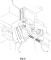
- a holding device of the crimping cassette 10 is shown in more detail.
- the holding device comprises a bracket having two claws 21a, 21b which are normally pushed together, via a spring to be described further below, into a clamping position or locked position.
- An unlocking push button 25 is coupled to an unlocking lever 26 to release the claws 21a, 21b and described in more detail below.
- a crimping tool assembly comprises a base plate 31 on which a stationary crimp tool part 32 is fixed.
- the claws 21a, 21b clamp the base plate 31.
- the crimping tool assembly comprises a coupling 35 which is configured such that a movable crimping tool part can be releasably coupled to the stationary crimp tool part.
- the crimp tool parts 31, comprise a crimp anvil and a crimp indentor, respectively (see also Fig. 18 ).
- the stationary and movable tool parts are shifted in a lateral direction.
- Fig. 3 shows a schematic side view of the holding device.
- Corresponding schematic top views of the holding device in a locked position, in an unlocked closed position, and in an open position are respectively shown in Figs. 4 to 6 .
- the claws 21a, 21b are pushed into a clamping or closed state by a closing spring 22.
- the claws 21a, 21b are firmly clamped to a mounting part of the base plate.
- the unlocked closed position Fig. 5
- the claws 21a, 21b loosely grip the mounting part for allowing an adjustment movement of the stationary tool part within a spatially limited adjustment range.
- the open position Fig. 6
- the claws 21a, 21b are released from the mounting part.
- a mandrel 23 is provided at the holding device.
- the unlocking lever 26 Upon operation of the unlocking push button 25, the unlocking lever 26 is pivoted and moves the mandrel 23 linearly.
- a back face 23a of the mandrel 23 is shaped such that when it is pushed against a corresponding face of the claws 21a, 21b, the claws 21a, 21b are tightened to the mounting part.
- a front surface 23b of the mandrel 23 is shaped such that when it is pushed against a corresponding face of the claws 21a, 21b, the claws 21a, 21b are spread open. In the shown example, the mandrel 23 pushes against rollers 24, which in turn spread the claws 21a, 21b.
- the mandrel In an idle state in the unlocked closed position ( Fig. 5 ), the mandrel substantially does not touch any of the faces on the claws 21a, 21b, thus allowing a limited spatial aligning movement of the tool parts.
- the locking device comprises, in addition to parts for attaching to the crimping cassette 10, elements for unlocking and opening the claws.
- a lever 61 is passively pivoted by a pulling force of a spring 64 at a time where the locking device is moved out as a whole ( Fig. 8 ).
- an opening lever 62 may be actuated by a pneumatic cylinder 63 ( Fig. 9 ).
- Both the lever 61 and the opening lever 62 act on the unlocking push button 25 of the holding device.
- the unlocking push button 25 is then flush with the housing of the crimping cassette 10 and cannot be pushed in to such an extent that the claws 21a, 21b are opened entirely.
- Fig. 10 is a perspective view of a coupling device 35 arranged at the crimping device.
- the coupling device 35 is fixed at the movable tool part and comprises a conical end face which is adapted to be engaged with a corresponding conical bore provided on the stationary tool part.
- a latch bolt 36 is provided which is pushed sidewards when the end face of the coupling device 35 is inserted into the bore. The latch bolt 36 is then reset into its initial position by a spring (not shown) and fixes the end face of the coupling device 35.
- the mounting device 51 comprises a gripper 53 which is pivotable around a rotation axis 53a.
- a pulling rod 54 can be actuated by a pneumatic cylinder (not shown) which pushes the pulling rod 54, which in turn moves a yoke 55 at which the pulling rod 54 and the gripper 53 are fixed, into the downwards direction.
- a pneumatic cylinder not shown
- this movement is counteracted by a push spring which pulls up the gripper 53 into an upper position.
- the gripper 53 is inserted into the yoke 55 and has contact parts with two elements.
- the rotation axis 53a is one of the elements, and the rotation axis 53a allows for a rotational movement of the gripper 53.
- a bolt 53b, as the other one of the elements, is another contact element of the gripper 53.
- a mounting piece each comprising a push spring and a spring holder are provided on each lateral sides of the rotation axis 53a.
- the mounting pieces are held within a groove on the mounting device 51 and allow for a slight linear movement of the gripper.
- a trajectory outline 59 is provided as an auxiliary measure to make sure that the gripper performs a linear movement in the first place. Under normal conditions, the gripper is not in contact with the trajectory outline 59; however, in the exemplary case that an irregular movement occurs which would lead to a rotary or pivoting movement of the gripper, the gripper is guided along the trajectory outline 59
- the yoke 55 Upon moving the pneumatic cylinder outwardly, the yoke 55 is moved down. In a first stage, the mounting pieces make the gripper 53 move linearly downward ( Fig. 13 ). At the end of the first stage, the linear movement is limited by the grooves 58. Since the rotation axis 53a is fixed, the gripper 53 moves, along the trajectory outline 59, in a pivotal manner ( Fig. 14 ).
- FIG. 15 to 17 A gripping operation of the movable crimp tool part by the gripper is shown in an illustrative manner in Figs. 15 to 17 .
- Figs. 19 to 21 show a crimping press during alignment of the movable and stationary tool parts.
- the base plate 31 is provided with pressure sensors 40a, 40b.
- a third pressure sensor is provided but not shown in Figs 19 to 21 .
- the disclosure is not limited to a particular amount of pressure sensors 40a, 40b, and in general, one, two, three, or more pressure sensors 40a, 40b can be provided, dependent on the constructive measures and/or a desired accuracy.
- the pressure sensors 40a, 40b help to detect when the crimp anvil and the crimp indentor touch each other and prevent an excessive pressure from being exerted to the crimp anvil and the crimp indentor.
- supporting rollers 42 are provided to lower a friction between a mounting part and the attachment surface 41.
- the mounting part comprises a clamping element 43 and mounting cylinders 44.
- the supporting rollers 42 are optional parts and may be omitted; in particular, when using crimping contacts having a certain minimum size, the alignment may be performed without supporting rollers 42.
- the supporting rollers 42 protrude slightly from the attachment surface 41 in the shown example.
- a spring mechanism (not shown) bears the supporting rollers 42 such that each of the supporting rollers 42 may be pressed downwards by a load acting thereon, i. e. to be at least flush with the plane of the attachment surface 41 in the case of a sufficient load.
- the stationary tool part rests entirely on the attachment surface 41 and is virtually unaffected by the supporting rollers 42.
- the clamping element 43 is loosened, then the stationary tool part is inserted. Then, the movable tool part is lowered, and the alignment surfaces of the crimp anvil and the crimp indentor touch each other. This operation is monitored using the pressure sensors 40a, 40b. Depending on the applied forces, the optional supporting rollers 42 are pushed downwards, to make the stationary tool part rest entirely on the attachment surface 41. After the alignment is performed, the clamping element 43 is tightened.
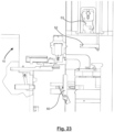
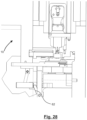
- Figs. 22-28 show different stages of a loading operation of the crimping cassette 10 in a crimping device of a cable processing apparatus.
- Fig. 22 the cassette 10 is in an initial position.
- Fig. 23 the locking device of the crimping device moves outward, and the gripper 53 is opened. If present, the lifting fork 52 is lowered.
- Fig. 24 the cassette 10 is moved to the right, and the unlocking push button 25 is operated.
- the stationary tool part can be aligned relative using the mounting cylinders 44.
- the alignment is performed by an aligning movement of a slit in the base plate 31 relative to a periphery of the mounting cylinder 44 and, in addition, relative to a periphery of the mounting cylinder below the clamping element 43 (cf. Fig. 20 ).
- Fig. 25 the movable tool part has been moved to the mounting device 51, and the cassette is moved further to the right.
- the coupling is open since the latch bolt 36 has been operated by an abutment 65.
- the movable tool part is gripped by the gripper 53. Thereafter, the moveable tool part is lifted, through the lifting fork 52, to the mounting device 51.
- the mounting device 51 is lowered towards the moveable tool part. In either case, the movable tool part is moved relative to the mounting device 51, such that the movable tool part and the mounting device 51 approach each other.
- the locking device is moved inwards, the cassette 10 is further moved to the right and clamped, and the movable tool part is lowered ( Fig. 27 ). Then the claws 21a, 21b are opened by pivoting the opening lever ( Fig. 28 ), whereby the stationary tool part is released.
Landscapes
- Engineering & Computer Science (AREA)
- Manufacturing & Machinery (AREA)
- Manufacturing Of Electrical Connectors (AREA)
Claims (14)
- Procédé d'alignement d'un outil de sertissage d'une cassette de sertissage dans un appareil de traitement de câbles,dans lequel la cassette de sertissage (10) comprend un outil de sertissage comportant une partie d'outil fixe et une partie d'outil mobile,dans lequel la cassette de sertissage (10) comprend en outre un dispositif de maintien comportant au moins deux mâchoires (21a, 21b) pour la fixation sur une partie de montage dans une zone de montage des mâchoires (21a, 21b), la partie de montage étant fixée directement ou indirectement à la partie d'outil fixe, dans lequel le dispositif de maintien présente :une position fermée verrouillée dans laquelle les mâchoires (21a, 21b) sont serrées fermement sur la partie de montage ;une position fermée déverrouillée dans laquelle les mâchoires (21a, 21b) saisissent lâchement la partie de montage pour permettre un mouvement d'ajustement de la partie d'outil fixe dans une plage d'ajustement spatialement limitée ;une position ouverte dans laquelle les mâchoires (21a, 21b) libèrent la partie de montage de telle façon que la partie d'outil fixe peut être séparée du dispositif de maintien,dans lequel l'appareil de traitement de câbles comprend une disposition de tension pour la partie de montage, adapté pour appliquer une force de tension à la partie de montage par rapport à une surface de fixation disposée sur le dispositif de sertissage,dans lequel les parties d'outil fixe et mobile de la cassette de sertissage (10) sont configurées pour agir conjointement dans une opération de sertissage du dispositif de sertissage de l'appareil de traitement de câbles,dans lequel le procédé comprend :le positionnement du dispositif de maintien dans la position fermée déverrouillée ;la libération du disposition de tension ;l'insertion de la partie d'outil fixe de l'outil de sertissage dans une zone de tension de la disposition de tension ;le déplacement de la partie d'outil mobile vers la partie d'outil fixe avant que la partie d'outil mobile ne touche la partie d'outil fixe ;le positionnement du dispositif de maintien dans la position ouverte ;le déplacement de la partie d'outil mobile vers la partie d'outil fixe jusqu'à ce qu'une force de pression entre la partie d'outil mobile et la partie d'outil fixe soit atteinte ou dépassée, de manière à obtenir un alignement dans la plage d'ajustement entre la partie d'outil mobile et la partie d'outil fixe ;l'application d'une tension avec la disposition de tension.
- Procédé selon la revendication 1, dans lequel la cassette de sertissage (10) comprend en outre un dispositif d'actionnement adapté pour actionner le dispositif de maintien au moins entre la position fermée verrouillée et la position fermée déverrouillée.
- Procédé selon l'une quelconque des revendications précédentes, dans lequel l'appareil de traitement de câbles comprend un dispositif de sertissage et un dispositif de verrouillage, dans lequel le dispositif de verrouillage est configuré pour actionner le dispositif d'actionnement de la cassette de sertissage afin de verrouiller la cassette de sertissage de façon libérable,dans lequel l'appareil de traitement de câbles comprend en outre un dispositif de montage configuré pour monter la partie d'outil mobile de l'outil de sertissage d'une cassette de sertissage chargée,dans lequel le dispositif de montage comprend un préhenseur,dans lequel le procédé comprend en outre :le déplacement du dispositif de verrouillage vers la cassette de sertissage (10) à charger ;l'actionnement du dispositif d'actionnement pour amener le dispositif de maintien dans la position fermée déverrouillée ;la fixation de la cassette de sertissage au dispositif de verrouillage ;la libération de la partie d'outil mobile par rapport à la partie d'outil fixe ;le déplacement de la partie d'outil mobile par rapport au dispositif de montage de manière à rapprocher l'outil mobile et le dispositif de montage ;la préhension de la partie complémentaire de préhension de la partie d'outil mobile avec le préhenseur.
- Procédé selon l'une quelconque des revendications précédentes, dans lequel, dans la cassette de sertissage (10), un ressort de fermeture est disposé et conçu de manière à fermer la préhension des mâchoires dans la position fermée déverrouillée.
- Procédé selon l'une quelconque des revendications précédentes, dans lequel, dans la position déverrouillée du dispositif de maintien, la plage d'ajustement spatialement limitée est substantiellement dans un plan perpendiculaire à un mouvement d'opération de sertissage de la partie d'outil mobile par rapport à la partie d'outil fixe.
- Procédé selon l'une quelconque des revendications précédentes, comprenant en outre :
lorsque le dispositif de maintien est dans la position fermée déverrouillée, le déplacement de la partie d'outil mobile vers la partie d'outil fixe dans une plus large mesure que lors de l'exécution d'une opération de sertissage, de manière à décaler mécaniquement la partie d'outil fixe dans la plage d'ajustement spatialement limitée. - Procédé selon l'une quelconque des revendications précédentes, dans lequel le dispositif de maintien comprend en outre un mandrin comportant :une face arrière formée de telle façon que lorsqu'elle est poussée contre une face correspondante des mâchoires (21a, 21b), les mâchoires (21a, 21b) sont serrées, dans la zone de montage, sur la partie de montage,une face avant formée de telle façon que lorsqu'elle est poussée contre une face correspondante des mâchoires, les mâchoires sont écartées,le procédé comprenant en outre :
le déplacement du mandrin vers un état inactif dans lequel aucune parmi la face arrière ou la face avant n'est poussée contre les mâchoires afin de faciliter une opération d'alignement de parties d'outil dans la position fermée déverrouillée du dispositif de maintien. - Procédé selon l'une quelconque des revendications précédentes, dans lequel l'outil de sertissage comprend en outre un dispositif d'accouplement, dans lequel le procédé comprend en outre l'accouplement libérable de la partie d'outil mobile avec la partie d'outil fixe.
- Procédé selon l'une quelconque des revendications précédentes,
dans lequel le préhenseur est configuré et conçu pour être déplaçable en fonction d'une trajectoire de préhension pour saisir une partie complémentaire de préhension de l'outil mobile, dans lequel la trajectoire de préhension comprend, dans un mouvement du préhenseur permettant de saisir la partie complémentaire de préhension, une trajectoire linéaire et une trajectoire de pivotement consécutive. - Procédé selon la revendication 9, dans lequel le préhenseur est conçu et formé de manière à être déplacé en fonction de la trajectoire de préhension lors de l'application d'une force à une face d'actionnement du préhenseur, la force présentant une direction constante sur l'ensemble du déplacement du préhenseur en fonction de la trajectoire de préhension.
- Procédé selon l'une quelconque des revendications précédentes, dans lequel l'appareil de traitement de câbles comprend en outre un actionneur, dans lequel le procédé comprend en outre l'ouverture du préhenseur par actionnement du cylindre pneumatique.
- Procédé selon l'une quelconque des revendications précédentes, dans lequel l'appareil de traitement de câbles comprend en outre un dispositif de levage, dans lequel le procédé comprend en outre le levage de la partie d'outil mobile vers le dispositif de montage.
- Procédé selon l'une quelconque des revendications précédentes, dans lequel l'appareil de traitement de câbles comprend en outre un détecteur de pression conçu pour détecter une force de pression entre la partie d'outil mobile et la partie d'outil fixe, et un dispositif de limitation de course relié au détecteur de pression, dans lequel le procédé comprend en outre :
la limitation, par le biais du dispositif de limitation de course, d'une course de la partie d'outil mobile par rapport à la partie d'outil fixe lors de la détection d'une force de pression supérieure à une force de pression maximale prédéterminée. - Procédé selon l'une quelconque des revendications précédentes, dans lequel la cassette de sertissage (10) comprend en outre un bouton poussoir de déverrouillage (25) couplé à un levier de déverrouillage (26) en tant que dispositif d'actionnement actionnable pour libérer les mâchoires (21a, 21b), dans lequel le dispositif de verrouillage de l'appareil de traitement de câbles comprend en outre un levier (61) pivoté passivement par une force de tension d'un ressort (64) à un moment où le dispositif de verrouillage est entièrement retiré, et dans lequel le dispositif de verrouillage de l'appareil de traitement de câbles comprend en outre un levier d'ouverture activable par un cylindre pneumatique (63) en tant qu'actionneur.
Priority Applications (3)
| Application Number | Priority Date | Filing Date | Title |
|---|---|---|---|
| RS20250472A RS66795B1 (sr) | 2017-06-30 | 2017-06-30 | Postupak poravnavanja za uređaj za obradu kablova |
| MA60138A MA60138B1 (fr) | 2017-06-30 | 2017-06-30 | Procédé d'alignement d'appareil de traitement de câble |
| EP22164420.6A EP4080693B1 (fr) | 2017-06-30 | 2017-06-30 | Procédé d'alignement d'appareil de traitement de câble |
Applications Claiming Priority (3)
| Application Number | Priority Date | Filing Date | Title |
|---|---|---|---|
| EP17742380.3A EP3646415B1 (fr) | 2017-06-30 | 2017-06-30 | Appareil de traitement de câble |
| PCT/EP2017/066341 WO2019001740A1 (fr) | 2017-06-30 | 2017-06-30 | Appareil de traitement de câble |
| EP22164420.6A EP4080693B1 (fr) | 2017-06-30 | 2017-06-30 | Procédé d'alignement d'appareil de traitement de câble |
Related Parent Applications (1)
| Application Number | Title | Priority Date | Filing Date |
|---|---|---|---|
| EP17742380.3A Division EP3646415B1 (fr) | 2017-06-30 | 2017-06-30 | Appareil de traitement de câble |
Publications (2)
| Publication Number | Publication Date |
|---|---|
| EP4080693A1 EP4080693A1 (fr) | 2022-10-26 |
| EP4080693B1 true EP4080693B1 (fr) | 2025-02-19 |
Family
ID=59383536
Family Applications (2)
| Application Number | Title | Priority Date | Filing Date |
|---|---|---|---|
| EP22164420.6A Active EP4080693B1 (fr) | 2017-06-30 | 2017-06-30 | Procédé d'alignement d'appareil de traitement de câble |
| EP17742380.3A Active EP3646415B1 (fr) | 2017-06-30 | 2017-06-30 | Appareil de traitement de câble |
Family Applications After (1)
| Application Number | Title | Priority Date | Filing Date |
|---|---|---|---|
| EP17742380.3A Active EP3646415B1 (fr) | 2017-06-30 | 2017-06-30 | Appareil de traitement de câble |
Country Status (8)
| Country | Link |
|---|---|
| US (2) | US11451000B2 (fr) |
| EP (2) | EP4080693B1 (fr) |
| JP (1) | JP6989626B2 (fr) |
| CN (2) | CN113851908B (fr) |
| MA (2) | MA49490B1 (fr) |
| MX (1) | MX2019015426A (fr) |
| RS (2) | RS66795B1 (fr) |
| WO (1) | WO2019001740A1 (fr) |
Families Citing this family (4)
| Publication number | Priority date | Publication date | Assignee | Title |
|---|---|---|---|---|
| EP3599683A1 (fr) * | 2018-07-24 | 2020-01-29 | Komax Holding Ag | Système de machine de traitement de câbles et procédé de réception d'un ou d'une pluralité de câbles du bac de réception d'un système de machine de traitement du câble |
| DE102019101016A1 (de) * | 2019-01-16 | 2020-07-16 | Harting Electric Gmbh & Co. Kg | Verfahren und Vorrichtung zur Überprüfung der Qualität einer Crimpung |
| US11735882B2 (en) * | 2021-06-09 | 2023-08-22 | Te Connectivity Solutions Gmbh | Terminal applicator to cassette mounting apparatus |
| CN113871997B (zh) * | 2021-10-21 | 2024-08-30 | 献县华桥线缆有限公司 | 一种电力电缆接续压接机及压接方法 |
Family Cites Families (21)
| Publication number | Priority date | Publication date | Assignee | Title |
|---|---|---|---|---|
| US4928379A (en) * | 1986-04-24 | 1990-05-29 | Amphenol Corporation | Press for use in aligning and terminating flat cable |
| US5794333A (en) * | 1996-08-13 | 1998-08-18 | Ut Automotive Dearborn, Inc. | Method and a unit for changing a die during wire termination |
| EP1341269B1 (fr) * | 2002-02-22 | 2006-10-11 | Komax Holding Ag | Presse de sertissage pour la réalisation de connexions de sertissage |
| EP1381123B1 (fr) | 2002-07-10 | 2011-06-22 | Komax Holding AG | Presse de sertissage avec un dispositif d'alimentation |
| JP2005141909A (ja) * | 2002-07-10 | 2005-06-02 | Komax Holding Ag | コンタクトフィード付き圧着プレス |
| JP3947448B2 (ja) | 2002-09-19 | 2007-07-18 | 矢崎総業株式会社 | 端子圧着装置 |
| JP5172072B2 (ja) * | 2003-10-28 | 2013-03-27 | コマツクス・ホールデイング・アー・ゲー | ワイヤ処理装置 |
| US20060191132A1 (en) * | 2005-02-28 | 2006-08-31 | John Mezzalingua Associates, Inc. | Coax connector compression tool |
| WO2006136930A1 (fr) | 2005-06-23 | 2006-12-28 | Schleuniger Holding Ag | Sertisseuse pour differents processus de sertissage et de pressage en particulier destinee a un ensemble cable |
| JP4898463B2 (ja) * | 2007-01-16 | 2012-03-14 | 矢崎総業株式会社 | 端子圧着装置及び端子圧着方法 |
| TW201135088A (en) * | 2010-04-09 | 2011-10-16 | Gison Machinery Co Ltd | Clamp for connection of sheet material |
| JP2012153509A (ja) * | 2011-01-27 | 2012-08-16 | Daifuku Co Ltd | ロール体用搬送車 |
| DE202011107870U1 (de) | 2011-11-14 | 2013-02-18 | Schäfer Werkzeug- und Sondermaschinenbau GmbH | Variable Zuführeinrichtung für ein Crimpaggregat |
| EP2738886B1 (fr) * | 2012-12-03 | 2020-06-03 | Komax Holding AG | Dispositif et procédé de fabrication d'une connexion par sertissage |
| EP2797182B1 (fr) * | 2013-04-24 | 2020-06-17 | Komax Holding AG | Dispositif de confection de câbles pour le raccourcissement, l'isolement et la confection d'un câble doté de contacts à sertir |
| EP2854245A3 (fr) * | 2013-09-30 | 2015-07-01 | Greenlee Textron Inc. | Machine à dénuder et ensemble de coupe pour dénuder un câble |
| WO2015171845A2 (fr) | 2014-05-09 | 2015-11-12 | Odyssey Tool, L.L.C. | Support d'outil et taquet de poussée à libération rapide pour un applicateur de borne |
| TWI635668B (zh) * | 2014-05-12 | 2018-09-11 | 美商Pct國際有限公司 | 具有對齊及壓縮特徵的同軸電纜連接器 |
| EP3065221A1 (fr) * | 2015-03-03 | 2016-09-07 | Delphi Technologies, Inc. | Procédé permettant d'établir une connexion entre au moins deux câbles et dispositif permettant de fournir une connexion de câble isolé |
| RS59238B1 (sr) | 2016-04-27 | 2019-10-31 | Komax Holding Ag | Uređaj za zamenu alata za krimpovanje i postupak zamene prvog alata za krimpovanje, postavljenog u položaju za obradu na presi za krimpovanje, nekim drugim alatom za krimpovanje |
| CN106253021A (zh) * | 2016-09-22 | 2016-12-21 | 中铁四局集团电气化工程有限公司 | 单芯低压电缆头制作一体机 |
-
2017
- 2017-06-30 RS RS20250472A patent/RS66795B1/sr unknown
- 2017-06-30 RS RS20220601A patent/RS63334B1/sr unknown
- 2017-06-30 MA MA49490A patent/MA49490B1/fr unknown
- 2017-06-30 EP EP22164420.6A patent/EP4080693B1/fr active Active
- 2017-06-30 WO PCT/EP2017/066341 patent/WO2019001740A1/fr not_active Ceased
- 2017-06-30 JP JP2019572386A patent/JP6989626B2/ja active Active
- 2017-06-30 MA MA60138A patent/MA60138B1/fr unknown
- 2017-06-30 EP EP17742380.3A patent/EP3646415B1/fr active Active
- 2017-06-30 CN CN202111203469.1A patent/CN113851908B/zh active Active
- 2017-06-30 CN CN201780092739.1A patent/CN111095691B/zh active Active
- 2017-06-30 US US16/626,944 patent/US11451000B2/en active Active
- 2017-06-30 MX MX2019015426A patent/MX2019015426A/es unknown
-
2022
- 2022-08-15 US US17/888,202 patent/US11670902B2/en active Active
Also Published As
| Publication number | Publication date |
|---|---|
| CN113851908B (zh) | 2024-08-09 |
| MA60138B1 (fr) | 2025-05-30 |
| JP6989626B2 (ja) | 2022-01-05 |
| JP2020530935A (ja) | 2020-10-29 |
| US20200127428A1 (en) | 2020-04-23 |
| RS63334B1 (sr) | 2022-07-29 |
| MA49490A (fr) | 2020-05-06 |
| US11451000B2 (en) | 2022-09-20 |
| CN111095691B (zh) | 2021-11-05 |
| RS66795B1 (sr) | 2025-06-30 |
| EP3646415A1 (fr) | 2020-05-06 |
| EP4080693A1 (fr) | 2022-10-26 |
| MA49490B1 (fr) | 2022-07-29 |
| MX2019015426A (es) | 2020-02-17 |
| US20220393418A1 (en) | 2022-12-08 |
| EP3646415B1 (fr) | 2022-04-06 |
| WO2019001740A1 (fr) | 2019-01-03 |
| CN113851908A (zh) | 2021-12-28 |
| US11670902B2 (en) | 2023-06-06 |
| CN111095691A (zh) | 2020-05-01 |
Similar Documents
| Publication | Publication Date | Title |
|---|---|---|
| US11670902B2 (en) | Aligning method for cable processing apparatus | |
| EP2853316B1 (fr) | Procédé de réunion temporaire de moule supérieur et de moule inférieur | |
| KR20110123216A (ko) | 체결 부품의 정렬 공급 장치 | |
| JP6160922B2 (ja) | クランプ装置 | |
| WO2016136821A1 (fr) | Dispositif de sortie et système de sortie | |
| EP3064322A1 (fr) | Dispositif de serrage avec des poignées amovibles | |
| JP7277551B2 (ja) | ケーブル加工装置のための位置合わせ方法 | |
| EP2322302A1 (fr) | Système comprenant une machine d'usinage, un mandrin de serrage, un élément de connexion d'une mâchoire de serrage, un appareil à changer des mâchoires ainsi qu' un procédé associé | |
| JP7314860B2 (ja) | せん断引張試験機、試験片のチャック装置及びチャック方法 | |
| US20240261983A1 (en) | Changer, Changer System and Method for Changing Tools to Be Used Consecutively on a Robotic Arm | |
| JP3871470B2 (ja) | 縦型治具用ロボットハンド | |
| US20070222130A1 (en) | Quick release mechanism | |
| TWI874592B (zh) | 氣動夾頭 | |
| JP2001121357A (ja) | ブーツバンドの取付方法および取付装置 | |
| KR101120630B1 (ko) | 펀치 조립체 | |
| JP4838174B2 (ja) | クランプ装置及びワークの自動調芯把持方法 | |
| US11541524B2 (en) | Tool-holding device, work machine with the tool-holding device, as well as a method for positioning a tool on a tool-holding device | |
| CN110865029B (zh) | 粘接力测试夹具、测试装置和测试方法 | |
| JPH0735691Y2 (ja) | クランクシャフト加工用保持装置 | |
| JP4370243B2 (ja) | 光ファイバケーブル用プラグのカシメ装置 | |
| CN118493433A (zh) | 工具保持装置、工具更换装置和工具更换方法 | |
| JPS633713Y2 (fr) | ||
| KR930008362B1 (ko) | 이형부품의 리이드 정열 및 교정장치 | |
| JPH052849U (ja) | パレツト治具のワーククランプ装置 | |
| JP2003010924A (ja) | 金属筒体の絞り方法 |
Legal Events
| Date | Code | Title | Description |
|---|---|---|---|
| PUAI | Public reference made under article 153(3) epc to a published international application that has entered the european phase |
Free format text: ORIGINAL CODE: 0009012 |
|
| STAA | Information on the status of an ep patent application or granted ep patent |
Free format text: STATUS: THE APPLICATION HAS BEEN PUBLISHED |
|
| AC | Divisional application: reference to earlier application |
Ref document number: 3646415 Country of ref document: EP Kind code of ref document: P |
|
| AK | Designated contracting states |
Kind code of ref document: A1 Designated state(s): AL AT BE BG CH CY CZ DE DK EE ES FI FR GB GR HR HU IE IS IT LI LT LU LV MC MK MT NL NO PL PT RO RS SE SI SK SM TR |
|
| STAA | Information on the status of an ep patent application or granted ep patent |
Free format text: STATUS: REQUEST FOR EXAMINATION WAS MADE |
|
| 17P | Request for examination filed |
Effective date: 20230330 |
|
| RAV | Requested validation state of the european patent: fee paid |
Extension state: MA Effective date: 20230330 |
|
| RBV | Designated contracting states (corrected) |
Designated state(s): AL AT BE BG CH CY CZ DE DK EE ES FI FR GB GR HR HU IE IS IT LI LT LU LV MC MK MT NL NO PL PT RO RS SE SI SK SM TR |
|
| RIC1 | Information provided on ipc code assigned before grant |
Ipc: H01R 43/048 20060101ALN20240724BHEP Ipc: H01R 43/055 20060101AFI20240724BHEP |
|
| GRAP | Despatch of communication of intention to grant a patent |
Free format text: ORIGINAL CODE: EPIDOSNIGR1 |
|
| STAA | Information on the status of an ep patent application or granted ep patent |
Free format text: STATUS: GRANT OF PATENT IS INTENDED |
|
| RIC1 | Information provided on ipc code assigned before grant |
Ipc: H01R 43/048 20060101ALN20240911BHEP Ipc: H01R 43/055 20060101AFI20240911BHEP |
|
| INTG | Intention to grant announced |
Effective date: 20240919 |
|
| GRAS | Grant fee paid |
Free format text: ORIGINAL CODE: EPIDOSNIGR3 |
|
| GRAA | (expected) grant |
Free format text: ORIGINAL CODE: 0009210 |
|
| STAA | Information on the status of an ep patent application or granted ep patent |
Free format text: STATUS: THE PATENT HAS BEEN GRANTED |
|
| AC | Divisional application: reference to earlier application |
Ref document number: 3646415 Country of ref document: EP Kind code of ref document: P |
|
| AK | Designated contracting states |
Kind code of ref document: B1 Designated state(s): AL AT BE BG CH CY CZ DE DK EE ES FI FR GB GR HR HU IE IS IT LI LT LU LV MC MK MT NL NO PL PT RO RS SE SI SK SM TR |
|
| REG | Reference to a national code |
Ref country code: GB Ref legal event code: FG4D |
|
| REG | Reference to a national code |
Ref country code: CH Ref legal event code: EP |
|
| REG | Reference to a national code |
Ref country code: IE Ref legal event code: FG4D |
|
| REG | Reference to a national code |
Ref country code: DE Ref legal event code: R096 Ref document number: 602017087970 Country of ref document: DE |
|
| REG | Reference to a national code |
Ref country code: MA Ref legal event code: VAGR Ref document number: 60138 Country of ref document: MA Kind code of ref document: B1 |
|
| REG | Reference to a national code |
Ref country code: NL Ref legal event code: MP Effective date: 20250219 |
|
| PG25 | Lapsed in a contracting state [announced via postgrant information from national office to epo] |
Ref country code: FI Free format text: LAPSE BECAUSE OF FAILURE TO SUBMIT A TRANSLATION OF THE DESCRIPTION OR TO PAY THE FEE WITHIN THE PRESCRIBED TIME-LIMIT Effective date: 20250219 |
|
| PG25 | Lapsed in a contracting state [announced via postgrant information from national office to epo] |
Ref country code: PL Free format text: LAPSE BECAUSE OF FAILURE TO SUBMIT A TRANSLATION OF THE DESCRIPTION OR TO PAY THE FEE WITHIN THE PRESCRIBED TIME-LIMIT Effective date: 20250219 |
|
| PG25 | Lapsed in a contracting state [announced via postgrant information from national office to epo] |
Ref country code: ES Free format text: LAPSE BECAUSE OF FAILURE TO SUBMIT A TRANSLATION OF THE DESCRIPTION OR TO PAY THE FEE WITHIN THE PRESCRIBED TIME-LIMIT Effective date: 20250219 |
|
| REG | Reference to a national code |
Ref country code: LT Ref legal event code: MG9D |
|
| PG25 | Lapsed in a contracting state [announced via postgrant information from national office to epo] |
Ref country code: IS Free format text: LAPSE BECAUSE OF FAILURE TO SUBMIT A TRANSLATION OF THE DESCRIPTION OR TO PAY THE FEE WITHIN THE PRESCRIBED TIME-LIMIT Effective date: 20250619 Ref country code: NO Free format text: LAPSE BECAUSE OF FAILURE TO SUBMIT A TRANSLATION OF THE DESCRIPTION OR TO PAY THE FEE WITHIN THE PRESCRIBED TIME-LIMIT Effective date: 20250519 |
|
| PG25 | Lapsed in a contracting state [announced via postgrant information from national office to epo] |
Ref country code: NL Free format text: LAPSE BECAUSE OF FAILURE TO SUBMIT A TRANSLATION OF THE DESCRIPTION OR TO PAY THE FEE WITHIN THE PRESCRIBED TIME-LIMIT Effective date: 20250219 |
|
| PG25 | Lapsed in a contracting state [announced via postgrant information from national office to epo] |
Ref country code: HR Free format text: LAPSE BECAUSE OF FAILURE TO SUBMIT A TRANSLATION OF THE DESCRIPTION OR TO PAY THE FEE WITHIN THE PRESCRIBED TIME-LIMIT Effective date: 20250219 |
|
| PG25 | Lapsed in a contracting state [announced via postgrant information from national office to epo] |
Ref country code: PT Free format text: LAPSE BECAUSE OF FAILURE TO SUBMIT A TRANSLATION OF THE DESCRIPTION OR TO PAY THE FEE WITHIN THE PRESCRIBED TIME-LIMIT Effective date: 20250620 Ref country code: LV Free format text: LAPSE BECAUSE OF FAILURE TO SUBMIT A TRANSLATION OF THE DESCRIPTION OR TO PAY THE FEE WITHIN THE PRESCRIBED TIME-LIMIT Effective date: 20250219 |
|
| PG25 | Lapsed in a contracting state [announced via postgrant information from national office to epo] |
Ref country code: GR Free format text: LAPSE BECAUSE OF FAILURE TO SUBMIT A TRANSLATION OF THE DESCRIPTION OR TO PAY THE FEE WITHIN THE PRESCRIBED TIME-LIMIT Effective date: 20250520 Ref country code: BG Free format text: LAPSE BECAUSE OF FAILURE TO SUBMIT A TRANSLATION OF THE DESCRIPTION OR TO PAY THE FEE WITHIN THE PRESCRIBED TIME-LIMIT Effective date: 20250219 |
|
| REG | Reference to a national code |
Ref country code: AT Ref legal event code: MK05 Ref document number: 1769267 Country of ref document: AT Kind code of ref document: T Effective date: 20250219 |
|
| PG25 | Lapsed in a contracting state [announced via postgrant information from national office to epo] |
Ref country code: SE Free format text: LAPSE BECAUSE OF FAILURE TO SUBMIT A TRANSLATION OF THE DESCRIPTION OR TO PAY THE FEE WITHIN THE PRESCRIBED TIME-LIMIT Effective date: 20250219 |
|
| PG25 | Lapsed in a contracting state [announced via postgrant information from national office to epo] |
Ref country code: SM Free format text: LAPSE BECAUSE OF FAILURE TO SUBMIT A TRANSLATION OF THE DESCRIPTION OR TO PAY THE FEE WITHIN THE PRESCRIBED TIME-LIMIT Effective date: 20250219 |
|
| PG25 | Lapsed in a contracting state [announced via postgrant information from national office to epo] |
Ref country code: DK Free format text: LAPSE BECAUSE OF FAILURE TO SUBMIT A TRANSLATION OF THE DESCRIPTION OR TO PAY THE FEE WITHIN THE PRESCRIBED TIME-LIMIT Effective date: 20250219 |
|
| PG25 | Lapsed in a contracting state [announced via postgrant information from national office to epo] |
Ref country code: AT Free format text: LAPSE BECAUSE OF FAILURE TO SUBMIT A TRANSLATION OF THE DESCRIPTION OR TO PAY THE FEE WITHIN THE PRESCRIBED TIME-LIMIT Effective date: 20250219 |
|
| PG25 | Lapsed in a contracting state [announced via postgrant information from national office to epo] |
Ref country code: CZ Free format text: LAPSE BECAUSE OF FAILURE TO SUBMIT A TRANSLATION OF THE DESCRIPTION OR TO PAY THE FEE WITHIN THE PRESCRIBED TIME-LIMIT Effective date: 20250219 Ref country code: EE Free format text: LAPSE BECAUSE OF FAILURE TO SUBMIT A TRANSLATION OF THE DESCRIPTION OR TO PAY THE FEE WITHIN THE PRESCRIBED TIME-LIMIT Effective date: 20250219 |
|
| PG25 | Lapsed in a contracting state [announced via postgrant information from national office to epo] |
Ref country code: SK Free format text: LAPSE BECAUSE OF FAILURE TO SUBMIT A TRANSLATION OF THE DESCRIPTION OR TO PAY THE FEE WITHIN THE PRESCRIBED TIME-LIMIT Effective date: 20250219 |
|
| REG | Reference to a national code |
Ref country code: DE Ref legal event code: R097 Ref document number: 602017087970 Country of ref document: DE |
|
| PLBE | No opposition filed within time limit |
Free format text: ORIGINAL CODE: 0009261 |
|
| STAA | Information on the status of an ep patent application or granted ep patent |
Free format text: STATUS: NO OPPOSITION FILED WITHIN TIME LIMIT |
|
| REG | Reference to a national code |
Ref country code: CH Ref legal event code: L10 Free format text: ST27 STATUS EVENT CODE: U-0-0-L10-L00 (AS PROVIDED BY THE NATIONAL OFFICE) Effective date: 20251231 |
|
| REG | Reference to a national code |
Ref country code: CH Ref legal event code: U11 Free format text: ST27 STATUS EVENT CODE: U-0-0-U10-U11 (AS PROVIDED BY THE NATIONAL OFFICE) Effective date: 20260105 |
|
| PGFP | Annual fee paid to national office [announced via postgrant information from national office to epo] |
Ref country code: DE Payment date: 20251211 Year of fee payment: 9 |
|
| PGFP | Annual fee paid to national office [announced via postgrant information from national office to epo] |
Ref country code: IT Payment date: 20251223 Year of fee payment: 9 |
|
| PGFP | Annual fee paid to national office [announced via postgrant information from national office to epo] |
Ref country code: RO Payment date: 20251216 Year of fee payment: 9 |
|
| 26N | No opposition filed |
Effective date: 20251120 |
|
| PGFP | Annual fee paid to national office [announced via postgrant information from national office to epo] |
Ref country code: RS Payment date: 20251212 Year of fee payment: 9 |
|
| PG25 | Lapsed in a contracting state [announced via postgrant information from national office to epo] |
Ref country code: MC Free format text: LAPSE BECAUSE OF FAILURE TO SUBMIT A TRANSLATION OF THE DESCRIPTION OR TO PAY THE FEE WITHIN THE PRESCRIBED TIME-LIMIT Effective date: 20250219 |
|
| VSFP | Annual fee paid to validation state [announced via postgrant information from national office to epo] |
Ref country code: MA Payment date: 20251216 Year of fee payment: 9 |
|
| PG25 | Lapsed in a contracting state [announced via postgrant information from national office to epo] |
Ref country code: LU Free format text: LAPSE BECAUSE OF NON-PAYMENT OF DUE FEES Effective date: 20250630 |
|
| GBPC | Gb: european patent ceased through non-payment of renewal fee |
Effective date: 20250630 |
|
| REG | Reference to a national code |
Ref country code: BE Ref legal event code: MM Effective date: 20250630 |
|
| PG25 | Lapsed in a contracting state [announced via postgrant information from national office to epo] |
Ref country code: GB Free format text: LAPSE BECAUSE OF NON-PAYMENT OF DUE FEES Effective date: 20250630 |
|
| PG25 | Lapsed in a contracting state [announced via postgrant information from national office to epo] |
Ref country code: IE Free format text: LAPSE BECAUSE OF NON-PAYMENT OF DUE FEES Effective date: 20250630 |
|
| PG25 | Lapsed in a contracting state [announced via postgrant information from national office to epo] |
Ref country code: BE Free format text: LAPSE BECAUSE OF NON-PAYMENT OF DUE FEES Effective date: 20250630 |
|
| PG25 | Lapsed in a contracting state [announced via postgrant information from national office to epo] |
Ref country code: FR Free format text: LAPSE BECAUSE OF NON-PAYMENT OF DUE FEES Effective date: 20250630 |
|
| PGFP | Annual fee paid to national office [announced via postgrant information from national office to epo] |
Ref country code: CH Payment date: 20260105 Year of fee payment: 9 |