EP4082584A1 - Procédé de traitement de gaz, chambre de stockage, incubateur, et stérilisateur - Google Patents
Procédé de traitement de gaz, chambre de stockage, incubateur, et stérilisateur Download PDFInfo
- Publication number
- EP4082584A1 EP4082584A1 EP20906332.0A EP20906332A EP4082584A1 EP 4082584 A1 EP4082584 A1 EP 4082584A1 EP 20906332 A EP20906332 A EP 20906332A EP 4082584 A1 EP4082584 A1 EP 4082584A1
- Authority
- EP
- European Patent Office
- Prior art keywords
- gas
- space
- treating apparatus
- sterilizing
- closed space
- Prior art date
- Legal status (The legal status is an assumption and is not a legal conclusion. Google has not performed a legal analysis and makes no representation as to the accuracy of the status listed.)
- Withdrawn
Links
- 238000000034 method Methods 0.000 title claims abstract description 60
- 238000000354 decomposition reaction Methods 0.000 claims abstract description 49
- 239000013076 target substance Substances 0.000 claims abstract description 43
- CBENFWSGALASAD-UHFFFAOYSA-N Ozone Chemical compound [O-][O+]=O CBENFWSGALASAD-UHFFFAOYSA-N 0.000 claims abstract description 33
- 238000007599 discharging Methods 0.000 claims abstract description 4
- 230000001678 irradiating effect Effects 0.000 claims abstract description 4
- 230000001954 sterilising effect Effects 0.000 claims description 97
- 238000004659 sterilization and disinfection Methods 0.000 claims description 32
- IAYPIBMASNFSPL-UHFFFAOYSA-N Ethylene oxide Chemical compound C1CO1 IAYPIBMASNFSPL-UHFFFAOYSA-N 0.000 claims description 26
- 239000000126 substance Substances 0.000 claims description 15
- 150000001299 aldehydes Chemical class 0.000 claims description 5
- 238000009434 installation Methods 0.000 claims description 4
- 239000001963 growth medium Substances 0.000 claims description 3
- 239000012855 volatile organic compound Substances 0.000 abstract description 50
- 239000007789 gas Substances 0.000 description 287
- WSFSSNUMVMOOMR-UHFFFAOYSA-N Formaldehyde Chemical compound O=C WSFSSNUMVMOOMR-UHFFFAOYSA-N 0.000 description 106
- QVGXLLKOCUKJST-UHFFFAOYSA-N atomic oxygen Chemical compound [O] QVGXLLKOCUKJST-UHFFFAOYSA-N 0.000 description 19
- IKHGUXGNUITLKF-UHFFFAOYSA-N Acetaldehyde Chemical group CC=O IKHGUXGNUITLKF-UHFFFAOYSA-N 0.000 description 16
- QTBSBXVTEAMEQO-UHFFFAOYSA-N Acetic acid Chemical compound CC(O)=O QTBSBXVTEAMEQO-UHFFFAOYSA-N 0.000 description 14
- 238000005259 measurement Methods 0.000 description 14
- -1 hydroxyl radicals Chemical class 0.000 description 13
- 238000006243 chemical reaction Methods 0.000 description 12
- 239000001301 oxygen Substances 0.000 description 12
- 229910052760 oxygen Inorganic materials 0.000 description 12
- 238000012360 testing method Methods 0.000 description 12
- OKKJLVBELUTLKV-UHFFFAOYSA-N Methanol Chemical compound OC OKKJLVBELUTLKV-UHFFFAOYSA-N 0.000 description 11
- CURLTUGMZLYLDI-UHFFFAOYSA-N Carbon dioxide Chemical compound O=C=O CURLTUGMZLYLDI-UHFFFAOYSA-N 0.000 description 9
- 230000000052 comparative effect Effects 0.000 description 8
- 150000003254 radicals Chemical class 0.000 description 8
- WSFSSNUMVMOOMR-NJFSPNSNSA-N methanone Chemical compound O=[14CH2] WSFSSNUMVMOOMR-NJFSPNSNSA-N 0.000 description 7
- MHAJPDPJQMAIIY-UHFFFAOYSA-N Hydrogen peroxide Chemical compound OO MHAJPDPJQMAIIY-UHFFFAOYSA-N 0.000 description 6
- 229910002092 carbon dioxide Inorganic materials 0.000 description 6
- 238000010586 diagram Methods 0.000 description 6
- GRVDJDISBSALJP-UHFFFAOYSA-N methyloxidanyl Chemical compound [O]C GRVDJDISBSALJP-UHFFFAOYSA-N 0.000 description 6
- XLYOFNOQVPJJNP-UHFFFAOYSA-N water Substances O XLYOFNOQVPJJNP-UHFFFAOYSA-N 0.000 description 5
- 231100001261 hazardous Toxicity 0.000 description 4
- NUJOXMJBOLGQSY-UHFFFAOYSA-N manganese dioxide Chemical compound O=[Mn]=O NUJOXMJBOLGQSY-UHFFFAOYSA-N 0.000 description 4
- 125000000963 oxybis(methylene) group Chemical group [H]C([H])(*)OC([H])([H])* 0.000 description 4
- 125000004430 oxygen atom Chemical group O* 0.000 description 4
- 238000013032 photocatalytic reaction Methods 0.000 description 4
- WTFNSXYULBQCQV-UHFFFAOYSA-N $l^{1}-oxidanyloxymethane Chemical compound CO[O] WTFNSXYULBQCQV-UHFFFAOYSA-N 0.000 description 3
- 241000588724 Escherichia coli Species 0.000 description 3
- SXRSQZLOMIGNAQ-UHFFFAOYSA-N Glutaraldehyde Chemical compound O=CCCCC=O SXRSQZLOMIGNAQ-UHFFFAOYSA-N 0.000 description 3
- KDLHZDBZIXYQEI-UHFFFAOYSA-N Palladium Chemical compound [Pd] KDLHZDBZIXYQEI-UHFFFAOYSA-N 0.000 description 3
- 241000191967 Staphylococcus aureus Species 0.000 description 3
- TUCNEACPLKLKNU-UHFFFAOYSA-N acetyl Chemical compound C[C]=O TUCNEACPLKLKNU-UHFFFAOYSA-N 0.000 description 3
- 125000002777 acetyl group Chemical group [H]C([H])([H])C(*)=O 0.000 description 3
- 238000005273 aeration Methods 0.000 description 3
- 239000001569 carbon dioxide Substances 0.000 description 3
- 239000003054 catalyst Substances 0.000 description 3
- 230000000694 effects Effects 0.000 description 3
- 125000002485 formyl group Chemical group [H]C(*)=O 0.000 description 3
- VUZPPFZMUPKLLV-UHFFFAOYSA-N methane;hydrate Chemical compound C.O VUZPPFZMUPKLLV-UHFFFAOYSA-N 0.000 description 3
- 125000000466 oxiranyl group Chemical group 0.000 description 3
- 239000011941 photocatalyst Substances 0.000 description 3
- ZWLUXSQADUDCSB-UHFFFAOYSA-N phthalaldehyde Chemical compound O=CC1=CC=CC=C1C=O ZWLUXSQADUDCSB-UHFFFAOYSA-N 0.000 description 3
- BASFCYQUMIYNBI-UHFFFAOYSA-N platinum Chemical compound [Pt] BASFCYQUMIYNBI-UHFFFAOYSA-N 0.000 description 3
- 229920001817 Agar Polymers 0.000 description 2
- 241000894006 Bacteria Species 0.000 description 2
- UQSXHKLRYXJYBZ-UHFFFAOYSA-N Iron oxide Chemical compound [Fe]=O UQSXHKLRYXJYBZ-UHFFFAOYSA-N 0.000 description 2
- KFSLWBXXFJQRDL-UHFFFAOYSA-N Peracetic acid Chemical compound CC(=O)OO KFSLWBXXFJQRDL-UHFFFAOYSA-N 0.000 description 2
- 238000000862 absorption spectrum Methods 0.000 description 2
- IKHGUXGNUITLKF-XPULMUKRSA-N acetaldehyde Chemical compound [14CH]([14CH3])=O IKHGUXGNUITLKF-XPULMUKRSA-N 0.000 description 2
- 239000008272 agar Substances 0.000 description 2
- 238000012258 culturing Methods 0.000 description 2
- 238000000295 emission spectrum Methods 0.000 description 2
- 239000000835 fiber Substances 0.000 description 2
- 230000005283 ground state Effects 0.000 description 2
- 239000001257 hydrogen Substances 0.000 description 2
- 229910052739 hydrogen Inorganic materials 0.000 description 2
- CBOIHMRHGLHBPB-UHFFFAOYSA-N hydroxymethyl Chemical compound O[CH2] CBOIHMRHGLHBPB-UHFFFAOYSA-N 0.000 description 2
- 239000013067 intermediate product Substances 0.000 description 2
- 239000002184 metal Substances 0.000 description 2
- 229910052751 metal Inorganic materials 0.000 description 2
- 229910000480 nickel oxide Inorganic materials 0.000 description 2
- 230000001575 pathological effect Effects 0.000 description 2
- 230000002085 persistent effect Effects 0.000 description 2
- 239000000047 product Substances 0.000 description 2
- 239000010948 rhodium Substances 0.000 description 2
- 229910052724 xenon Inorganic materials 0.000 description 2
- FHNFHKCVQCLJFQ-UHFFFAOYSA-N xenon atom Chemical compound [Xe] FHNFHKCVQCLJFQ-UHFFFAOYSA-N 0.000 description 2
- UFHFLCQGNIYNRP-UHFFFAOYSA-N Hydrogen Chemical compound [H][H] UFHFLCQGNIYNRP-UHFFFAOYSA-N 0.000 description 1
- 206010028980 Neoplasm Diseases 0.000 description 1
- 241000282376 Panthera tigris Species 0.000 description 1
- VYPSYNLAJGMNEJ-UHFFFAOYSA-N Silicium dioxide Chemical compound O=[Si]=O VYPSYNLAJGMNEJ-UHFFFAOYSA-N 0.000 description 1
- 238000010521 absorption reaction Methods 0.000 description 1
- 230000002411 adverse Effects 0.000 description 1
- 125000003172 aldehyde group Chemical group 0.000 description 1
- 229910052782 aluminium Inorganic materials 0.000 description 1
- XAGFODPZIPBFFR-UHFFFAOYSA-N aluminium Chemical compound [Al] XAGFODPZIPBFFR-UHFFFAOYSA-N 0.000 description 1
- PNEYBMLMFCGWSK-UHFFFAOYSA-N aluminium oxide Inorganic materials [O-2].[O-2].[O-2].[Al+3].[Al+3] PNEYBMLMFCGWSK-UHFFFAOYSA-N 0.000 description 1
- 125000004429 atom Chemical group 0.000 description 1
- 230000001580 bacterial effect Effects 0.000 description 1
- 201000011510 cancer Diseases 0.000 description 1
- 230000000711 cancerogenic effect Effects 0.000 description 1
- 231100000315 carcinogenic Toxicity 0.000 description 1
- 239000000919 ceramic Substances 0.000 description 1
- 229910010293 ceramic material Inorganic materials 0.000 description 1
- 230000001332 colony forming effect Effects 0.000 description 1
- 238000004891 communication Methods 0.000 description 1
- 238000007796 conventional method Methods 0.000 description 1
- 238000001514 detection method Methods 0.000 description 1
- 239000003989 dielectric material Substances 0.000 description 1
- 230000002708 enhancing effect Effects 0.000 description 1
- 238000011156 evaluation Methods 0.000 description 1
- 238000001704 evaporation Methods 0.000 description 1
- 230000005281 excited state Effects 0.000 description 1
- 239000008098 formaldehyde solution Substances 0.000 description 1
- 229910052839 forsterite Inorganic materials 0.000 description 1
- 238000010438 heat treatment Methods 0.000 description 1
- 230000036512 infertility Effects 0.000 description 1
- 229910010272 inorganic material Inorganic materials 0.000 description 1
- 239000011147 inorganic material Substances 0.000 description 1
- JEIPFZHSYJVQDO-UHFFFAOYSA-N iron(III) oxide Inorganic materials O=[Fe]O[Fe]=O JEIPFZHSYJVQDO-UHFFFAOYSA-N 0.000 description 1
- 230000031700 light absorption Effects 0.000 description 1
- HCWCAKKEBCNQJP-UHFFFAOYSA-N magnesium orthosilicate Chemical compound [Mg+2].[Mg+2].[O-][Si]([O-])([O-])[O-] HCWCAKKEBCNQJP-UHFFFAOYSA-N 0.000 description 1
- 229910044991 metal oxide Inorganic materials 0.000 description 1
- 150000004706 metal oxides Chemical class 0.000 description 1
- 230000000813 microbial effect Effects 0.000 description 1
- 239000000203 mixture Substances 0.000 description 1
- 229910052754 neon Inorganic materials 0.000 description 1
- GKAOGPIIYCISHV-UHFFFAOYSA-N neon atom Chemical compound [Ne] GKAOGPIIYCISHV-UHFFFAOYSA-N 0.000 description 1
- 230000003647 oxidation Effects 0.000 description 1
- 238000007254 oxidation reaction Methods 0.000 description 1
- GNRSAWUEBMWBQH-UHFFFAOYSA-N oxonickel Chemical compound [Ni]=O GNRSAWUEBMWBQH-UHFFFAOYSA-N 0.000 description 1
- 229910052763 palladium Inorganic materials 0.000 description 1
- 230000001699 photocatalysis Effects 0.000 description 1
- 238000007146 photocatalysis Methods 0.000 description 1
- 229910052697 platinum Inorganic materials 0.000 description 1
- 230000002035 prolonged effect Effects 0.000 description 1
- 230000009257 reactivity Effects 0.000 description 1
- 239000011347 resin Substances 0.000 description 1
- 229920005989 resin Polymers 0.000 description 1
- 229910052703 rhodium Inorganic materials 0.000 description 1
- MHOVAHRLVXNVSD-UHFFFAOYSA-N rhodium atom Chemical compound [Rh] MHOVAHRLVXNVSD-UHFFFAOYSA-N 0.000 description 1
- 230000001953 sensory effect Effects 0.000 description 1
- 229910001220 stainless steel Inorganic materials 0.000 description 1
- 239000010935 stainless steel Substances 0.000 description 1
- 238000011144 upstream manufacturing Methods 0.000 description 1
Images


Classifications
-
- A—HUMAN NECESSITIES
- A61—MEDICAL OR VETERINARY SCIENCE; HYGIENE
- A61L—METHODS OR APPARATUS FOR STERILISING MATERIALS OR OBJECTS IN GENERAL; DISINFECTION, STERILISATION OR DEODORISATION OF AIR; CHEMICAL ASPECTS OF BANDAGES, DRESSINGS, ABSORBENT PADS OR SURGICAL ARTICLES; MATERIALS FOR BANDAGES, DRESSINGS, ABSORBENT PADS OR SURGICAL ARTICLES
- A61L9/00—Disinfection, sterilisation or deodorisation of air
- A61L9/16—Disinfection, sterilisation or deodorisation of air using physical phenomena
- A61L9/18—Radiation
- A61L9/20—Ultraviolet radiation
-
- B—PERFORMING OPERATIONS; TRANSPORTING
- B01—PHYSICAL OR CHEMICAL PROCESSES OR APPARATUS IN GENERAL
- B01D—SEPARATION
- B01D53/00—Separation of gases or vapours; Recovering vapours of volatile solvents from gases; Chemical or biological purification of waste gases, e.g. engine exhaust gases, smoke, fumes, flue gases, aerosols
- B01D53/007—Separation of gases or vapours; Recovering vapours of volatile solvents from gases; Chemical or biological purification of waste gases, e.g. engine exhaust gases, smoke, fumes, flue gases, aerosols by irradiation
-
- A—HUMAN NECESSITIES
- A61—MEDICAL OR VETERINARY SCIENCE; HYGIENE
- A61L—METHODS OR APPARATUS FOR STERILISING MATERIALS OR OBJECTS IN GENERAL; DISINFECTION, STERILISATION OR DEODORISATION OF AIR; CHEMICAL ASPECTS OF BANDAGES, DRESSINGS, ABSORBENT PADS OR SURGICAL ARTICLES; MATERIALS FOR BANDAGES, DRESSINGS, ABSORBENT PADS OR SURGICAL ARTICLES
- A61L2202/00—Aspects relating to methods or apparatus for disinfecting or sterilising materials or objects
- A61L2202/10—Apparatus features
- A61L2202/13—Biocide decomposition means, e.g. catalysts, sorbents
-
- A—HUMAN NECESSITIES
- A61—MEDICAL OR VETERINARY SCIENCE; HYGIENE
- A61L—METHODS OR APPARATUS FOR STERILISING MATERIALS OR OBJECTS IN GENERAL; DISINFECTION, STERILISATION OR DEODORISATION OF AIR; CHEMICAL ASPECTS OF BANDAGES, DRESSINGS, ABSORBENT PADS OR SURGICAL ARTICLES; MATERIALS FOR BANDAGES, DRESSINGS, ABSORBENT PADS OR SURGICAL ARTICLES
- A61L2209/00—Aspects relating to disinfection, sterilisation or deodorisation of air
- A61L2209/10—Apparatus features
- A61L2209/14—Filtering means
-
- B—PERFORMING OPERATIONS; TRANSPORTING
- B01—PHYSICAL OR CHEMICAL PROCESSES OR APPARATUS IN GENERAL
- B01D—SEPARATION
- B01D2257/00—Components to be removed
- B01D2257/70—Organic compounds not provided for in groups B01D2257/00 - B01D2257/602
- B01D2257/708—Volatile organic compounds V.O.C.'s
-
- B—PERFORMING OPERATIONS; TRANSPORTING
- B01—PHYSICAL OR CHEMICAL PROCESSES OR APPARATUS IN GENERAL
- B01D—SEPARATION
- B01D2258/00—Sources of waste gases
- B01D2258/06—Polluted air
-
- B—PERFORMING OPERATIONS; TRANSPORTING
- B01—PHYSICAL OR CHEMICAL PROCESSES OR APPARATUS IN GENERAL
- B01D—SEPARATION
- B01D2259/00—Type of treatment
- B01D2259/45—Gas separation or purification devices adapted for specific applications
- B01D2259/4508—Gas separation or purification devices adapted for specific applications for cleaning air in buildings
-
- B—PERFORMING OPERATIONS; TRANSPORTING
- B01—PHYSICAL OR CHEMICAL PROCESSES OR APPARATUS IN GENERAL
- B01D—SEPARATION
- B01D2259/00—Type of treatment
- B01D2259/45—Gas separation or purification devices adapted for specific applications
- B01D2259/4525—Gas separation or purification devices adapted for specific applications for storage and dispensing systems
-
- B—PERFORMING OPERATIONS; TRANSPORTING
- B01—PHYSICAL OR CHEMICAL PROCESSES OR APPARATUS IN GENERAL
- B01D—SEPARATION
- B01D2259/00—Type of treatment
- B01D2259/80—Employing electric, magnetic, electromagnetic or wave energy, or particle radiation
- B01D2259/804—UV light
Definitions
- the present invention relates to a gas treatment method, and more particularly to a method for treating a gas that exists inside a closed space.
- the present invention also relates to a storage chamber, an incubator, and a sterilizer that use this method.
- Patent Document 1 A structure disclosed in Patent Document 1 below, for example, is known for storage rooms (storage chambers) for storing such medical tools or instruments.
- the storage chamber disclosed in Patent Document 1 includes an air circulation path for forced circulation of air inside the storage chamber.
- a UV lamp for sterilization and a photocatalyst plate for photocatalytic reactions that enable the decomposition of acetaldehyde or formaldehyde.
- Patent Document 1 JP-A-2006-333954
- Sterilization methods for medical tools are internationally standardized. Sterilization methods are roughly classified into heat processes and application of chemicals used for sterilization such as formaldehyde, orthophthalaldehyde, glutaraldehyde, EOG (Ethylene Oxide Gas), hydrogen peroxide, or peracetic acid.
- the heating process is applicable only to medical tools that can be heated. If a medical tool includes a resin part such as fiber parts of an endoscope, for example, thermal sterilization is not applicable because the fiber parts will deform by heat. In such cases, normally, methods that use sterilizing chemicals are employed.
- hydrogen peroxide is applicable to a very limited range of sterilization targets because hydrogen peroxide may cause oxidation of the target objects.
- chemicals such as formaldehyde and ethylene oxide are commonly used for sterilization.
- Formaldehyde is likely to cause cancer, and therefore EOG is recommended over formaldehyde in recent years (see 'Guideline for Sterility Assurance in Healthcare Setting 2015' edited by Japanese Society of Medical Instrumentation ).
- the sterilizer After performing a sterilization process to a medical tool in which EOG is introduced into a sterilizer, the sterilizer is exhausted of EOG by aeration, to remove EOG adhered to the medical tool. After that, the medical tool that has been sterilized is stored in a storage chamber.
- ethylene oxide tends to be persistent and it is very difficult to prevent a small amount of ethylene oxide from being left in or on the medical tools. Consequently, the remaining ethylene oxide vaporizes and is released as EOG into the storage chamber during storage inside the storage chamber. There is thus a risk that an operator who opens the door of the storage chamber to take out a medical tool from the storage chamber may inhale EOG inside the storage chamber. While considered to be less carcinogenic than formaldehyde, ethylene oxide is still regarded as a substance hazardous to the human body.
- Patent Document 1 In the storage chamber described in Patent Document 1, a UV lamp is provided for the sterilization of the storage target itself as well as for causing photocatalytic reactions. While Patent Document 1 does not mention ethylene oxide, the document describes the decomposition of acetaldehyde and formaldehyde by photocatalytic reactions. Acetaldehyde and formaldehyde are highly volatile similar to ethylene oxide and classified as VOCs (Volatile Organic Compounds).
- an object of the present invention is to provide a gas treatment method that enables treatment of VOCs with higher decomposition efficiency than before in cases where a gas containing treatment target substances classified as VOCs exists inside a closed space.
- Another object of the present invention is to provide a storage chamber, an incubator, and a sterilizer which are, by the use of this gas treatment method, capable of decomposing treatment target substances classified as VOCs contained in the gas inside the closed space with high efficiency.
- the present invention resides in a gas treatment method for treating a gas inside a space, the gas being an air containing a treatment target substance classified as a VOC and existing inside a closed space, the method including the steps of:
- radicals that are generated by irradiating a gas inside a closed space with vacuum UV light decompose a treatment target substance.
- O( 1 D) represents oxygen atoms in the excited state
- O( 3 P) represents oxygen atoms in the ground state.
- hv( ⁇ ) indicates absorption of light of a wavelength ⁇ .
- the treatment target substance decomposes highly efficiently due to the very high reactivity of hydroxyl radicals (• OH) obtained by Formula (2).
- Oxygen atoms O( 3 P) generated by the reaction of Formula (1) react with the oxygen (O 2 ) contained in the air inside the closed space and generate ozone (O 3 ) by the reaction expressed by following Formula (6).
- the gas after the treatment is discharged through an ozone decomposition filter into the closed space.
- treatment target substances classified as VOCs contained in the gas inside the closed space are decomposed by the step (b), and further, the step (c) decomposes ozone which is a secondary product generated by execution of the step (b).
- the ozone decomposition filter may be disposed of such as to allow the gas discharged from the gas treating apparatus to flow through.
- the ozone decomposition filter may be disposed of inside the gas treating apparatus.
- the gas treating apparatus may include:
- the housing may have a smaller cross-sectional area of a flow path in a space irradiated with the vacuum UV light than a cross-sectional area of an opening at the gas inlet.
- Vacuum UV light is strongly absorbed by oxygen. Therefore, if the cross-sectional area of an opening in the space irradiated with vacuum UV light, i.e., the diameter of the gas flow path, is too large, an increased amount of gas may be discharged out of the housing without being irradiated with vacuum UV light, which may reduce the speed at which the treatment target substance decomposes.
- the steps (a) and (b) are performed by the gas treating apparatus having a housing in which the cross-sectional area of the opening in the space irradiated with vacuum UV light is made smaller than the cross-sectional area of the opening at the gas inlet. This increases the ratio of the gas irradiated with vacuum UV light to the gas introduced into the housing. This allows an increased amount of radicals to be generated and enhances the efficiency of decomposition of treatment target substances in the gas.
- the gas treating apparatus may include a fan, and a power supply unit that drives the fan and the excimer lamp.
- the step (a) may be a step of drawing the gas inside the closed space into the gas treating apparatus by the fan, and the steps (a) to (c) may be repeatedly performed in which the gas discharged from the gas treating apparatus into the closed space by the step (c) is taken into the closed space again by the step (a).
- the gas inside the closed space is repeatedly irradiated with UV light from the gas treating apparatus, so that the treatment target substances contained in the gas inside the closed space decompose with even higher efficiency.
- the treatment target substance may be a substance containing at least one of the groups consisting of ethylene oxide and aldehydes.
- aldehydes' herein refer to substances that include an aldehyde group (also called formyl group) such as formaldehyde, acetaldehyde, phthalaldehyde, and glutaraldehyde.
- aldehyde group also called formyl group
- the excimer lamp may include a light-emitting tube enclosed with a light-emitting gas containing Xe.
- the excimer lamp emits vacuum UV light having a main wavelength of 172 nm.
- the above gas treating apparatus may be placed at an installation position inside the closed space, and the steps (a) to (c) may be performed while the installation position of the gas treating apparatus inside the closed space is changed.
- the gas treating apparatus may be moved inside the closed space while the steps (a) to (c) are performed, so that, even when the gas treating apparatus is small as compared to the volume of the closed space, the concentration of the treatment target substances contained in the gas inside the closed space can be efficiently reduced.
- the above gas treatment method can be applied to storage chambers.
- the present invention resides in a storage chamber for which the above gas treatment method for treating a gas inside a space is used, the storage chamber including:
- the storage chamber stores sterilized medical tools and the like, for example.
- PROBLEMS TO BE SOLVED BY THE INVENTION a small amount of VOCs or treatment target substances inevitably remains on medical tools after the sterilization process, and it is possible that the gas inside the storage chamber contains the substances that have evaporated during storage.
- the storage chamber according to the present invention causes the decomposition of treatment target substances contained in the gas inside the storage chamber so that the concentration of treatment target substances in the storage chamber is reduced. Accordingly, when an operator opens the door to take out a medical tool stored in the storage chamber, there is less risk of the operator inhaling a gas containing a treatment target substance that may be hazardous to the human body at a concentration of more than a predetermined level.
- VOCs as the treatment target substances include acetaldehyde, formaldehyde, ethylene oxide as already mentioned above, as well as phthalaldehyde, glutaraldehyde, and the like.
- the above gas treatment method is applicable not only to storage chambers but also to an apparatus in which a gas inside a closed space may contain a treatment target substance.
- an incubator is an apparatus in which temperature and humidity are maintained at levels optimal for culturing cells or microbes. Some cells or microbes may release a gas containing a substance classified as a VOC such as acetaldehyde or formaldehyde during growth.
- the gas inside the incubator contains VOCs. Namely, similarly to the foregoing, when an operator opens the door of the incubator to take out a culture container, the gas containing VOCs may flow out into the work space and the operator may inhale the gas.
- the incubator using the gas treatment method for treating a gas inside a space described above allows decomposition of VOCs contained in the gas inside the incubator even during the culture of cells or microbes so that the concentration of treatment target substances in the incubator is reduced. Accordingly, when an operator opens the door to take out a culture container, there is less risk of the operator inhaling a gas containing a treatment target substance that may be hazardous to the human body at a concentration of more than a predetermined level.
- the present invention resides in an incubator for which the above gas treatment method for treating a gas inside a space is used, the incubator including:
- a sterilizer is an apparatus that performs a treatment mainly on medical tools to create an environment that prevents the growth of microbes. Specifically, a sterilizing gas such as EOG is introduced into a sealed space in which a medical tool as a sterilization target is accommodated for a predetermined period of time. The apparatus is then exhausted of the gas by aeration. Formaldehyde is also applicable as the sterilizing gas.
- the sterilizer using the gas treatment method for treating a gas inside a space described above allows the decomposition of VOCs contained in the gas inside the sterilizer by means of the gas treating apparatus so that the concentration of VOCs (treatment target substances) in the sterilizer is reduced. Accordingly, when an operator opens the door to take out a medical tool, there is less risk of the operator inhaling a gas containing a treatment target substance that may be hazardous to human body at a concentration of more than a predetermined level.
- the present invention resides in a sterilizer for which the above gas treatment method for treating a gas inside a space is used, the sterilizer including:
- the gas treating apparatus is installed inside the sterilizer. In this case, it is preferable to prevent the sterilizing gas introduced during the sterilization process from adhering to the ozone decomposition filter.
- the gas treating apparatus may include:
- the gas treating apparatus may be disposed of outside the sterilizer and configured to be connected to the sterilizer with a pipe.
- the present invention resides in a sterilizer for which the above gas treatment method for treating a gas inside a space is used, the sterilizer including:
- the sterilizer may include a valve disposed of in at least one of the gas introduction passage and the gas exhaust passage and configured to be able to let in, stop, and adjust a flow of the gas inside the sterilizing space into the gas treating apparatus.
- the VOC when a gas containing a treatment target substance classified as a VOC exists inside a closed space, the VOC can be treated with higher decomposition efficiency than before.
- Fig. 1 is a schematic block diagram illustrating a configuration of a storage chamber in a first embodiment of the present invention.
- the storage chamber 1 is an apparatus having a storage space 2 that is a closed space, for storing storage targets 6 such as medical tools, for example, inside this storage space 2.
- the storage chamber 1 includes a door 4 which is opened when a storage target 6 is put into the storage space 2, or when a stored storage target 6 is taken out of the storage chamber 1.
- the storage chamber 1 includes a gas treating apparatus 10 inside the storage space 2 that is enclosed by outer walls 3.
- This gas treating apparatus 10 takes in a gas G1 inside the storage space 2, performs a treatment to be described later to this gas G1, and discharges the gas (gas G2) into the same storage space 2.
- a gas Gz containing a treatment target substance classified as a VOC such as ethylene oxide adhering to the storage target 6 is released into the storage space 2 during storage.
- a formalin-fixed sample such as a pathological tissue is stored in the storage chamber 1 as a storage target 6, a gas Gz containing formaldehyde is released from this sample into the storage space 2 during storage in the storage chamber 1.
- the gas G1 inside the storage space 2 is composed of air containing such treatment target substances.
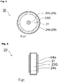
- Fig. 2 is a schematic plan view illustrating one example of the gas treating apparatus 10.
- the gas treating apparatus 10 includes a housing 11, an excimer lamp 20 accommodated inside the housing 11, an ozone decomposition filter 17, and a fan 18.
- the housing 11 includes a gas inlet 12 for introducing a gas G1 from outside the gas treating apparatus 10 into the gas treating apparatus 10, and a gas outlet 13 for discharging a gas G2 to the outside of the gas treating apparatus 10.
- the excimer lamp 20 has a light-emitting tube arranged longitudinally along direction d1 in which the gas G1 flows.
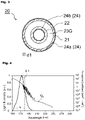
- Fig. 3 is a schematic cross-sectional view of an excimer lamp 20 cut in a plane orthogonal to direction d1.
- the excimer lamp 20 has light-emitting tubes made up of a tube member that is cylindrical and positioned outside (herein referred to as "outer tube 21") and a tube member disposed inside the outer tube 21, coaxial with the outer tube 21, and having a smaller inside diameter than that of the outer tube 21 (herein referred to as "inner tube 22").
- Both light-emitting tubes (21, 22) are made of a dielectric material such as synthetic quartz glass.
- the outer tube 21 and inner tube 22 are sealed at the ends in direction d1 (not shown) so that between the tubes there is formed a light-emitting space that is annular when viewed from direction d1.
- a light-emitting gas 23G that generates excimer molecules by an electric discharge is sealed in this light-emitting space.
- a more specific example of the light-emitting gas 23G is a gas mixture containing xenon (Xe) and neon (Ne) in a predetermined ratio which may or may not further include a small amount of oxygen or hydrogen.
- the excimer lamp 20 of this embodiment includes a first electrode 24a placed on an outer wall surface of the outer tube 21, and a second electrode 24b placed on an inner wall surface of the inner tube 22.
- the first electrode 24a is in the form of a mesh or a wire.
- the second electrode 24b is in the form of a film.
- the second electrode 24b may also be in the form of a mesh or wire similar to the first electrode 24a.
- the excimer lamp 20 has a base part 25 in end parts of direction d1 of the light-emitting tubes (21, 22).
- This base part 25 is made of a ceramic material (inorganic material) such as steatite, forsterite, sialon, alumina, and the like, and serves the function of securing the end of the light-emitting tubes (21, 22).
- Power supply lines (not shown) are connected to the respective electrodes (24a, 24b) through holes provided to the base parts 25 or via an outer edge of the base part 25.
- the wavelength of the UV light L1 can be changed by using a different substance for the light-emitting gas 23G.
- ArBr, ArCI, and F2 can be used for the light-emitting gas 23G, which respectively produce vacuum UV light with a peak wavelength near 165 nm, 175 nm, and 153 nm.
- the description here assumes that the light-emitting gas 23G enclosed in the excimer lamp 20 is a gas containing Xe.
- Fig. 4 is a graph showing an emission spectrum of UV light L1 emitted from the excimer lamp 20 enclosed with a light-emitting gas including Xe, overlapped with an oxygen (O 2 ) absorption spectrum.
- the horizontal axis represents the wavelength
- the left vertical axis represents the relative value of light intensity of the excimer lamp
- the right vertical axis represents the absorption coefficient of oxygen(O 2 ).
- the UV light L1 emitted from the excimer lamp 20 has a main wavelength within a wavelength band ⁇ 1 of 160 nm or more and less than 180 nm as shown in Fig. 4 . As illustrated in Fig. 4 , a large amount of light in this wavelength band ⁇ 1 is absorbed by oxygen (O 2 ).
- the gas treating apparatus 10 When the gas treating apparatus 10 starts operating inside the storage chamber 1, the gas G1 inside the storage space 2 is taken into the housing 11 from the gas inlet 12 (this corresponds to step (a)).
- the gas treating apparatus 10 shown in Fig. 2 is provided with a fan 18 for the purpose of enhancing the flow rate of the gas G1 taken into the gas treating apparatus 10.
- This fan 18 may be driven and controlled by a power supply unit (not shown) at the same time with power application to the excimer lamp 20.
- the gas G1 is an air containing treatment target substances classified as VOCs such as ethylene oxide released from the storage target 6.
- This gas G1 while flowing through the gas treating apparatus 10, is irradiated with UV light L1 of the wavelength band ⁇ 1 from the excimer lamp 20.
- This UV light L1 when absorbed by oxygen (O 2 ), causes reactions expressed by Formula (1) and Formula (2) set forth in the above section MEANS FOR SOLVING THE PROBLEMS.
- the formulas are as follows. O 2 + hv( ⁇ ) ⁇ O( 1 D) + O( 3 P) ⁇ (1) O( 1 D) + H 2 O ⁇ • OH + • OH ⁇ (2)
- Ethylene oxide or EO (herein expressed as "C 2 H 4 O") is decomposed by oxygen radicals (O( 1 D) or O( 3 P)), or hydroxyl radicals (• OH). Decomposition progresses as expressed by the following formulas, for example, and results in conversion into methanol (CH 3 OH) or formaldehyde (HCHO) as intermediate products.
- HCHO Formaldehyde produced by the decomposition of ethylene oxide (C 2 H 4 O) further decomposes into carbon dioxide and water by decomposition reactions that progress as follows by hydroxyl radicals (• OH).
- Hydrogen radicals (• H) are converted to hydroperoxyl radicals (• HO 2 ) by following Formula (5d). Hydroperoxyl radicals (• HO 2 ) are converted to hydroxyl radicals (• OH) by following Formula (5e) and used in the decomposition reactions of VOCs such as ethylene oxide and formaldehyde. Hydroperoxyl radicals (• HO 2 ) alone are also used in the decomposition reactions of VOCs. • H + O 2 ⁇ • HO 2 ⁇ (5d) • HO 2 + O 3 ⁇ • OH + 2O 2 ⁇ (5e)
- the gas treating apparatus 10 discharges the treated gas G2 into the storage space 2 into the storage space 2, the discharged gas is again introduced into the gas treating apparatus 10 as a gas G1 that is the treatment target.
- the reactions of the above Formulas (1) to (5c) progress further as the gas is repeatedly irradiated with the UV light L1 so that the concentration of ethylene oxide contained in the gas G1 inside the storage space 2 can be largely reduced.
- the VOC released from the storage target 6 is formaldehyde
- the VOC is decomposed in the gas treating apparatus 10 by the reactions of above Formulas (5a) to (5c).
- Oxygen atoms O( 3 P) generated by the reaction of Formula (1) react with oxygen (O 2 ) contained in the gas G1 and produce ozone (O 3 ) by Formula (6) set forth in the above section MEANS FOR SOLVING THE PROBLEMS.
- Formula (6) is as follows. O( 3 P) + O 2 ⁇ O 3 ⁇ (6)
- Ozone (O 3 ) is less reactive than radicals and may be left in the gas G2 and discharged from the gas outlet 13 into the storage space 2.
- Ozone (O 3 ) is also a substance known to affect the human body. Should the door 4 be opened when the gas G1 inside the storage space 2 still contains ozone (O 3 ), the operator may inhale the gas G1 containing ozone (O 3 ).
- the gas treating apparatus 10 includes an ozone decomposition filter 17 upstream of the gas outlet 13 (closer to the excimer lamp 20) as shown in Fig. 2 . Namely, the gas G2 after being irradiated with UV light L1 from the excimer lamp 20 is discharged through the ozone decomposition filter 17 into the storage space 2 (this corresponds to step (c)).
- ozone decomposition filter 17 for example, structures wherein a catalyst is carried on a base member having a honeycomb structure made of metal such as aluminum and stainless steel, or ceramics, may be employed.
- a catalyst rare metal catalysts such as palladium (Pd), rhodium (Rh), platinum (Pt) and the like, or metal oxides such as manganese dioxide (MnO 2 ), iron (II) oxide (Fe 2 O 3 ), nickel oxide (NiO) and the like may be used.
- radicals produced by irradiation of UV light L1 contribute to the decomposition reactions of VOCs such as ethylene oxide, while secondary products such as ozone can be removed by the ozone decomposition filter 17.
- UV light in the wavelength range of less than 200 nm is largely absorbed by oxygen as shown in Fig. 4 . Therefore, if the cross-sectional area of the flow path is too large in a region irradiated with UV light L1, an increased amount of gas G1 may be discharged from the gas treating apparatus 10 without being irradiated with and processed by UV light L1. On the other hand, if openings at the gas inlet 12 and gas outlet 13 have a cross-sectional area that is too small, the flow rate of the gas G1 flowing through the gas treating apparatus 10 will be reduced. In either case, there is a possibility of slowing down the speed of reducing the concentration of VOCs such as ethylene oxide contained in the gas G1 inside the storage space 2.
- VOCs such as ethylene oxide contained in the gas G1 inside the storage space 2.
- the cross-sectional area of the flow path in a region irradiated with UV light 1 where the gas G1 flows through smaller than the cross-sectional area of the openings at the gas inlet 12 and gas outlet 13, as in the gas treating apparatus 10 illustrated in Fig. 2 .
- This does not mean that the present invention excludes cases where the cross-sectional areas of the openings at the gas inlet 12 and gas outlet 13 are substantially equal to the cross-sectional area of the flow path in the region irradiated with UV light L1.
- Fig. 6 is a schematic cross-sectional view illustrating an excimer lamp 20 having a "flat-tube structure" and is drawn in accordance with Fig. 3 .
- the excimer lamp 20 illustrated in Fig. 6 has a single light-emitting tube 21 that is rectangular when viewed from the longitudinal direction, i.e., direction d1.
- the excimer lamp 20 includes a first electrode 24a placed on an outer wall surface on one side of the light-emitting tube 21, and a second electrode 24b placed on an outer wall surface of the light-emitting tube 21 at a position opposite the first electrode 24a.
- the first electrode 24a and second electrode 24b both have a mesh (reticular) or wire form so as not to inhibit the emission of the UV light L1 generated inside the light-emitting tube 21 out of the light-emitting tube 21.
- the cross-sectional shape of the excimer lamp 20 cut in a plane perpendicular to direction d1 is not limited to circular shown in Fig. 3 and Fig. 5 or rectangular shown in Fig. 6 . Various shapes can be adopted.
- Fig. 7 is a schematic plan view illustrating a configuration of an incubator in a second embodiment of the present invention.
- the incubator 40 is an apparatus in which temperature and humidity are maintained at levels optimal for culturing cells or microbes, and has a temperature/humidity regulator (not shown).
- the incubator 40 includes a culture room 42 which is a closed space enclosed by outer walls 43, with shelves 45 inside the culture room 42 for placing culture containers 46.
- the incubator 40 includes a door (not shown) that is opened when a culture container 46 is placed inside the culture room 42, or when a culture container 46 is taken out of the culture room 42.
- the culture container 46 is a container accommodating a culture medium for growing cells or microbes, and made up, for example, of Petri dishes. Some cells or microbes grown in the culture container 46 may release a gas Gz containing treatment target substances classified as VOCs such as acetaldehyde or formaldehyde during growth.
- VOCs treatment target substances classified as acetaldehyde or formaldehyde
- the gas G1 inside the culture room 42 is composed of air containing such treatment target substances.
- the incubator 40 in this embodiment includes a gas treating apparatus 10 similarly to the first embodiment. Therefore, formaldehyde, if contained in the gas Gz released from the culture container 46, is decomposed in the gas treating apparatus 10 by the reactions of above Formulas (5a) to (5e).
- Acetic acid decomposes into carbon dioxide and water by the decomposition reaction that progresses as follows by hydroxyl radicals (• OH).
- Formaldehyde decomposes into carbon dioxide and water by the reactions of Formulas (5a) to (5c) that progress as described in the first embodiment.
- the built-in gas treating apparatus 10 can lower the concentration of acetaldehyde or formaldehyde contained in the gas G1 inside the culture room 42 which is a closed space. Description of other configurations and treatment methods are the same as those of the first embodiment and will be omitted.
- the characteristic odor of formaldehyde may become an issue. Since the incubator 40 configured as described above can greatly reduce the concentration of formaldehyde contained in the gas G1 inside the incubator 40, the issue of the odor is also resolved. This issue will be described later with reference to an example.
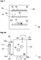
- Fig. 8A to Fig. 8C are schematic plan views illustrating a configuration of a sterilizer in the third embodiment of the present invention.
- the sterilizer 50 is an apparatus that performs a sterilization process on target objects such as medical tools to create an environment that prevents the growth of microbes.
- a specific example may be a medical tool as a storage target 6 stored in the storage chamber 1 of the first embodiment, i.e., a medical tool may be subjected to a sterilization process in the sterilizer 50 of this embodiment, after which it may be taken out of the sterilizer 50 and transferred to a storage chamber.
- the sterilizer 50 is an apparatus having a sterilizing space 52 that is a closed space, for storing sterilization targets 56 such as medical tools, for example, in this sterilizing space 52.
- the sterilizing space 52 is enclosed by outer walls 53.
- the sterilizer 50 includes a door (not shown) that is opened when a sterilization target 56 is placed inside the sterilizing space 52, or when a sterilization target 56 is taken out after the sterilization process.
- the sterilizer 50 includes a sterilizing gas source 58 and a sterilizing gas inlet 58a for introducing a sterilizing gas Gs such as EOG into the sterilizing space 52.
- the sterilizer 50 also includes an exhaust pump 59 and an exhaust port 59a for drawing the sterilizing gas Gs inside the sterilizing space 52 out of the sterilizer 50 after the sterilization process.
- the sterilizer 50 illustrated in Fig. 8A has a gas treating apparatus 10 disposed outside the sterilizing space 52.
- This gas treating apparatus 10 is in communication with the sterilizing space 52 through pipes (54a, 54b) for gas passage.
- the pipes (54a, 54b) are provided with valves 55 for controlling the gas flow between the gas treating apparatus and the sterilizing space 52.
- the sterilizing gas Gs is introduced from the sterilizing gas source 58, with a sterilization target 56 placed inside the sterilizing space 52 as illustrated in Fig. 8A .
- EOG or gaseous formaldehyde is used as the sterilizing gas Gs.
- the valves 55 in Fig. 8A at this time are closed so that the sterilizing gas Gs does not flow into the gas treating apparatus 10. This is for preventing the sterilizing gas Gs from adhering to the ozone decomposition filter 17 and compromising the ozone decomposition performance.
- the gas treating apparatus 10 for a predetermined time reduces the concentration of VOCs contained in the gas G1 inside the sterilizing space 52.
- the exhaust pump 59 is started to operate so that the gas G1 inside the sterilizing space 52 is drawn out of the sterilizer 50 from the exhaust port 59a as illustrated in Fig. 8C .
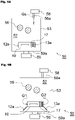
- the gas treating apparatus 10 may be disposed of inside the sterilizing space 52 as illustrated in Fig. 9A and Fig. 9B .
- the gas treating apparatus 10 may include shutters (12a, 13a) that can be opened and closed for controlling the introduction of a gas G1 that is present outside the gas treating apparatus 10 into the gas treating apparatus 10.
- the shutters (12a, 12b) are closed as illustrated in Fig. 9A .
- the shutters (12a, 13a) are opened as illustrated in Fig. 9B , and the gas treating apparatus 10 is activated.
- the sterilizing gas Gs is prevented from adhering to the ozone decomposition filter 17 and compromising the ozone decomposition performance.
- Fig. 10 is a schematic diagram of a storage chamber 1 used in Test 1.
- the storage chamber 1 has a box-shaped storage space 2 with a volume of 110L, including a gas treating apparatus 10 placed inside.
- the concentration of VOCs contained in the gas G1 inside the storage space 2 was measured while operating the gas treating apparatus 10 to determine changes with time.
- the VOC concentration measurement values are based on readings of an aldehyde sensor ("Tiger" made by RIKEN KEIKI CO., LTD.) placed inside the storage space 2.
- the fan 18 was driven so that the gas G1 contained inside the storage space 2 was introduced into the gas treating apparatus 10 at a rate of 0.3 m 3 /min.
- the horizontal axis of Fig. 11 represents the time that elapsed from the start of measurement, and the left and right vertical axes both indicate the concentration of formaldehyde contained in the gas G1 inside the storage space 2.
- the left and right vertical axes show different scales.
- data in Mode 1 is in accordance with the scale of the right vertical axis
- data in Mode 2 is in accordance with the scale of the left vertical axis.
- test results showed that, with the gas treating apparatus 10 placed inside the storage chamber 1 and operated, a large amount of formaldehyde could be decomposed by a process in a very short time.
- Fig. 12 is a schematic diagram of an incubator 40 used in Test 2.
- a cool incubator with a culture room 42 having a space volume of 25L (CN-25C made by Mitsubishi Electric Engineering Company, Limited) was employed as the incubator 40.
- Twenty 90 mm diameter Petri dishes were accommodated inside this culture room 42 as culture containers 46.
- 0.1 mL of Staphylococcus aureus (NBRC. 12732) was smeared on standard agar (Sample 1).
- NBRC. 106373 was smeared on standard agar (Sample 2).
- These twenty Petri dishes correspond to culture containers 46.
- Sample 1 Staphylococcus aureus was added to yield 100 to 300 CFU/Plate.
- Sample 2 Escherichia coli was added to yield 100 to 300 CFU/Plate.
- CFU stands for Colony Forming Unit.
- Example 1 the gas treating apparatus 10 was accommodated inside the incubator 40 with the culture containers 46 ( Fig. 12 ). On the other hand, the gas treating apparatus 10 was not employed in the incubator 40 in Comparative Example 1. In both Example 1 and Comparative Example 1, the VOC concentration and the odor inside the culture room 42 were measured to determine changes in accordance with time from the start of measurement. The results are shown in Fig. 13 .
- the horizontal axis of Fig. 13 represents the time [hour] that elapsed from the start of measurement
- the left vertical axis (a) represents the concentration of VOC contained in the gas G1 inside the culture room 42.
- the right vertical axis (b) indicates the intensity of odor inside the culture room 42 on a scale of 0 to 5 (6 levels).
- the VOC concentration measurement values are based on readings of an aldehyde sensor placed inside the culture room 42.
- the odor intensity levels are based on average values of a panel of 3 members in sensory evaluation based on Indication Method of Odor Intensity by 6-point scale.
- the odor intensity levels 0 to 5 each correspond to the descriptions in the following Table 1. [Table 1] Odor intensity Description 0 No odor 1 Odor that can only just be sensed (detection threshold concentration) 2 Slight odor by which the odor can be identified (recognition threshold concentration) 3 Odor that can easily be sensed 4 Strong odor 5 Intense odor
- Graphs (a) in Fig. 13 show that, in Example 1 which employed the gas treating apparatus 10, the VOC concentration was lower than 10 ppm even after 30 hours had passed from the start of measurement. On the other hand, in Comparative Example 1 which did not employ the gas treating apparatus 10, the VOC concentration rose rapidly from the start of measurement, and reached about 45 ppm after 10 hours. The VOC concentration then reduced with time but remained over 20 ppm.
- Graph (a) of Comparative Example 1 shows a slight reduction in VOC concentration after the elapse of 10 hours. This is assumed to be attributed to the slowing down of microbial growth and leaking of a slight amount of gas through minute gaps present in the incubator 40.
- Graphs (b) in Fig. 13 show that the odor inside the incubator 40 of Comparative Example 1 intensified to reach level 5 of odor intensity within 5 hours from the start of measurement and stayed at this intensity level even after the elapse of 30 hours. In contrast, while the odor intensity increased with time in the incubator 40 of Example 1, the odor intensity remained at level 3 even after the elapse of 30 hours.
- Table 2 shows the results of measurements of numbers of bacterial colonies contained in each of the samples of both Example 1 and Comparative Example 1 after 30 hours passed. The values are all average values of numbers of bacteria that exist on three Petri dishes.
- Table 2 shows that there is no significant difference in the numbers of colonies of both bacteria after the elapse of 30 hours between Example 1 which employed the gas treating apparatus 10 and Comparative Example 1 which did not employ the gas treating apparatus 10. This leads to a conclusion that the exhaust gas G2 from the gas treating apparatus 10 discharged into the culture room 42 does not adversely affect the cells being grown.
- the storage chamber 1 described in the first embodiment may have any configuration as long as a storage target 6 that releases a gas containing a treatment target substance classified as a VOC is stored inside the storage space 2 which is a closed space.
- a formalin-fixed sample such as a pathological tissue is transported in an automobile, either placed inside a cab sharing the same space as the driver's seat, or inside a trunk of an automobile in the form of a station wagon in which the trunk is connected to the passenger room, the cab or passenger room of such automobile corresponds to the storage chamber 1.
Landscapes
- Health & Medical Sciences (AREA)
- Chemical & Material Sciences (AREA)
- General Health & Medical Sciences (AREA)
- Engineering & Computer Science (AREA)
- Life Sciences & Earth Sciences (AREA)
- Public Health (AREA)
- Veterinary Medicine (AREA)
- Toxicology (AREA)
- Epidemiology (AREA)
- Animal Behavior & Ethology (AREA)
- Analytical Chemistry (AREA)
- General Chemical & Material Sciences (AREA)
- Oil, Petroleum & Natural Gas (AREA)
- Chemical Kinetics & Catalysis (AREA)
- Apparatus For Disinfection Or Sterilisation (AREA)
- Disinfection, Sterilisation Or Deodorisation Of Air (AREA)
Applications Claiming Priority (2)
| Application Number | Priority Date | Filing Date | Title |
|---|---|---|---|
| JP2019234723A JP7449479B2 (ja) | 2019-12-25 | 2019-12-25 | ガス処理方法、保管庫、インキュベータ、滅菌器 |
| PCT/JP2020/046696 WO2021131888A1 (fr) | 2019-12-25 | 2020-12-15 | Procédé de traitement de gaz, chambre de stockage, incubateur, et stérilisateur |
Publications (2)
| Publication Number | Publication Date |
|---|---|
| EP4082584A1 true EP4082584A1 (fr) | 2022-11-02 |
| EP4082584A4 EP4082584A4 (fr) | 2023-07-05 |
Family
ID=76575196
Family Applications (1)
| Application Number | Title | Priority Date | Filing Date |
|---|---|---|---|
| EP20906332.0A Withdrawn EP4082584A4 (fr) | 2019-12-25 | 2020-12-15 | Procédé de traitement de gaz, chambre de stockage, incubateur, et stérilisateur |
Country Status (4)
| Country | Link |
|---|---|
| EP (1) | EP4082584A4 (fr) |
| JP (1) | JP7449479B2 (fr) |
| CN (1) | CN114901319A (fr) |
| WO (1) | WO2021131888A1 (fr) |
Families Citing this family (2)
| Publication number | Priority date | Publication date | Assignee | Title |
|---|---|---|---|---|
| WO2023242998A1 (fr) * | 2022-06-15 | 2023-12-21 | ウシオ電機株式会社 | Équipement de protection respiratoire |
| CN119630466A (zh) * | 2022-08-03 | 2025-03-14 | 优志旺电机株式会社 | 气体分解方法及气体分解装置 |
Family Cites Families (18)
| Publication number | Priority date | Publication date | Assignee | Title |
|---|---|---|---|---|
| JPH0373152A (ja) * | 1989-08-14 | 1991-03-28 | Tomio Kishino | ガス減菌器 |
| JPH06238123A (ja) * | 1993-02-15 | 1994-08-30 | Mitsubishi Heavy Ind Ltd | 脱臭装置及びその運転方法 |
| JP3670876B2 (ja) * | 1998-09-29 | 2005-07-13 | 三洋電機株式会社 | 培養装置 |
| JP4051277B2 (ja) | 2002-12-18 | 2008-02-20 | カンケンテクノ株式会社 | 有害排ガス処理システム |
| JP2006333954A (ja) | 2005-05-31 | 2006-12-14 | Andes Denki Kk | 保管庫 |
| CN101784327A (zh) * | 2007-06-22 | 2010-07-21 | 开利公司 | 使用臭氧发生装置进行空气净化的方法和系统 |
| CN201598282U (zh) | 2009-12-28 | 2010-10-06 | 田军 | 净化恒温培养箱 |
| CN203034022U (zh) | 2013-01-29 | 2013-07-03 | 屈海涛 | 一种新型培养箱 |
| JP2014237090A (ja) | 2013-06-07 | 2014-12-18 | 株式会社メディテックジャパン | 酸化エチレンガスを含む廃ガスの処理装置及び処理方法 |
| DE112014007093B4 (de) | 2014-10-22 | 2019-05-02 | Helder da Costa Goncalves | Sterilisationsvorrichtung unter verwendung von durch mehrere kapillarrohre verdampftem und kombiniertem wasserstoffperoxid und ozon |
| CN204352741U (zh) * | 2014-11-19 | 2015-05-27 | 陆钢 | 有害气体净化装置 |
| JP6564663B2 (ja) * | 2015-09-29 | 2019-08-21 | 株式会社オーク製作所 | エキシマランプ装置 |
| JP6861945B2 (ja) | 2017-01-23 | 2021-04-21 | 三浦工業株式会社 | 低温蒸気ホルムアルデヒド滅菌装置 |
| DE202017007059U1 (de) * | 2017-03-16 | 2019-06-14 | Bluezone Ip Holding Llc | Luftbehandlungssystem |
| US10933159B2 (en) * | 2017-03-16 | 2021-03-02 | Bluezone Ip Holding Llc | Air treatment method |
| CN111278472A (zh) * | 2017-10-24 | 2020-06-12 | 英服Ip有限公司 | 空气处理系统以及使用所述空气处理系统的方法 |
| KR102432205B1 (ko) | 2017-12-27 | 2022-08-12 | 우시오덴키 가부시키가이샤 | 기체 처리 장치 |
| JP7379864B2 (ja) * | 2019-05-21 | 2023-11-15 | ウシオ電機株式会社 | 気体処理装置 |
-
2019
- 2019-12-25 JP JP2019234723A patent/JP7449479B2/ja active Active
-
2020
- 2020-12-15 EP EP20906332.0A patent/EP4082584A4/fr not_active Withdrawn
- 2020-12-15 WO PCT/JP2020/046696 patent/WO2021131888A1/fr not_active Ceased
- 2020-12-15 CN CN202080087992.XA patent/CN114901319A/zh active Pending
Also Published As
| Publication number | Publication date |
|---|---|
| CN114901319A (zh) | 2022-08-12 |
| JP7449479B2 (ja) | 2024-03-14 |
| JP2021101888A (ja) | 2021-07-15 |
| EP4082584A4 (fr) | 2023-07-05 |
| WO2021131888A1 (fr) | 2021-07-01 |
Similar Documents
| Publication | Publication Date | Title |
|---|---|---|
| JP4763012B2 (ja) | 滅菌方法及び装置 | |
| US10449263B2 (en) | Devices for disinfection, deodorization, and/or sterilization of objects | |
| KR101206360B1 (ko) | 화학 작용제 또는 생물학 작용제의 처리장치 및 방법 | |
| US4990311A (en) | Deodorizing apparatus and method | |
| CN111829099B (zh) | 用于空气气溶胶消毒兼有机气体降解的装置及方法 | |
| JP2008516652A (ja) | 周囲空気を滅菌するための方法及び装置 | |
| EP2199259A1 (fr) | Procédé de production d'eau à activité redox et appareil de production d'eau à activité redox | |
| EP4082584A1 (fr) | Procédé de traitement de gaz, chambre de stockage, incubateur, et stérilisateur | |
| JP7272390B2 (ja) | 殺菌方法 | |
| JPWO2019131124A1 (ja) | 気体処理装置 | |
| JP7039849B2 (ja) | 処理方法 | |
| US6707254B1 (en) | Low temperature plasma sterilising system and method | |
| JP6735485B2 (ja) | 滅菌方法及び滅菌装置 | |
| JP2012205615A (ja) | 気体処理装置 | |
| JP4433296B2 (ja) | 活性酸素殺菌装置及び活性酸素殺菌方法 | |
| JPH11505166A (ja) | 医療器材のためのドライ殺菌方法及び装置 | |
| JP5933182B2 (ja) | 有害物質除去装置及びこれを用いて空気浄化を行う空気浄化装置 | |
| JP6501486B2 (ja) | 滅菌装置 | |
| CN115867328A (zh) | 杀菌处理方法及杀菌处理装置 | |
| KR102254592B1 (ko) | 살균 방법 | |
| CN220110129U (zh) | 串联式带消解功能的氙准分子活性氧簇消毒器 | |
| CN219209522U (zh) | 氙准分子光源活性氧簇循环增浓车载消毒器 | |
| US20220105229A1 (en) | Ccfl sterilizing apparatus | |
| JP2006115973A (ja) | 活性酸素殺菌装置 | |
| WO2022195440A1 (fr) | Dispositif de désinfection pour l'air et/ou les surfaces d'un environnement à traiter et procédé de désinfection d'un environnement à traiter |
Legal Events
| Date | Code | Title | Description |
|---|---|---|---|
| STAA | Information on the status of an ep patent application or granted ep patent |
Free format text: STATUS: THE INTERNATIONAL PUBLICATION HAS BEEN MADE |
|
| PUAI | Public reference made under article 153(3) epc to a published international application that has entered the european phase |
Free format text: ORIGINAL CODE: 0009012 |
|
| STAA | Information on the status of an ep patent application or granted ep patent |
Free format text: STATUS: REQUEST FOR EXAMINATION WAS MADE |
|
| 17P | Request for examination filed |
Effective date: 20220722 |
|
| AK | Designated contracting states |
Kind code of ref document: A1 Designated state(s): AL AT BE BG CH CY CZ DE DK EE ES FI FR GB GR HR HU IE IS IT LI LT LU LV MC MK MT NL NO PL PT RO RS SE SI SK SM TR |
|
| DAV | Request for validation of the european patent (deleted) | ||
| DAX | Request for extension of the european patent (deleted) | ||
| A4 | Supplementary search report drawn up and despatched |
Effective date: 20230606 |
|
| RIC1 | Information provided on ipc code assigned before grant |
Ipc: B01D 53/00 20060101ALI20230531BHEP Ipc: A61L 9/20 20060101ALI20230531BHEP Ipc: A61L 9/00 20060101ALI20230531BHEP Ipc: A61L 2/20 20060101AFI20230531BHEP |
|
| STAA | Information on the status of an ep patent application or granted ep patent |
Free format text: STATUS: THE APPLICATION HAS BEEN WITHDRAWN |
|
| 18W | Application withdrawn |
Effective date: 20240723 |