EP4083742B1 - Appareil de travail robotisé - Google Patents
Appareil de travail robotisé Download PDFInfo
- Publication number
- EP4083742B1 EP4083742B1 EP22169814.5A EP22169814A EP4083742B1 EP 4083742 B1 EP4083742 B1 EP 4083742B1 EP 22169814 A EP22169814 A EP 22169814A EP 4083742 B1 EP4083742 B1 EP 4083742B1
- Authority
- EP
- European Patent Office
- Prior art keywords
- area
- working
- work
- traveling
- base
- Prior art date
- Legal status (The legal status is an assumption and is not a legal conclusion. Google has not performed a legal analysis and makes no representation as to the accuracy of the status listed.)
- Active
Links
Images






Classifications
-
- A—HUMAN NECESSITIES
- A01—AGRICULTURE; FORESTRY; ANIMAL HUSBANDRY; HUNTING; TRAPPING; FISHING
- A01D—HARVESTING; MOWING
- A01D34/00—Mowers; Mowing apparatus of harvesters
- A01D34/006—Control or measuring arrangements
- A01D34/008—Control or measuring arrangements for automated or remotely controlled operation
-
- G—PHYSICS
- G05—CONTROLLING; REGULATING
- G05D—SYSTEMS FOR CONTROLLING OR REGULATING NON-ELECTRIC VARIABLES
- G05D1/00—Control of position, course, altitude or attitude of land, water, air or space vehicles, e.g. using automatic pilots
- G05D1/02—Control of position or course in two dimensions
- G05D1/021—Control of position or course in two dimensions specially adapted to land vehicles
- G05D1/0212—Control of position or course in two dimensions specially adapted to land vehicles with means for defining a desired trajectory
- G05D1/0219—Control of position or course in two dimensions specially adapted to land vehicles with means for defining a desired trajectory ensuring the processing of the whole working surface
-
- G—PHYSICS
- G05—CONTROLLING; REGULATING
- G05D—SYSTEMS FOR CONTROLLING OR REGULATING NON-ELECTRIC VARIABLES
- G05D1/00—Control of position, course, altitude or attitude of land, water, air or space vehicles, e.g. using automatic pilots
- G05D1/02—Control of position or course in two dimensions
- G05D1/021—Control of position or course in two dimensions specially adapted to land vehicles
- G05D1/0212—Control of position or course in two dimensions specially adapted to land vehicles with means for defining a desired trajectory
- G05D1/0225—Control of position or course in two dimensions specially adapted to land vehicles with means for defining a desired trajectory involving docking at a fixed facility, e.g. base station or loading bay
-
- G—PHYSICS
- G05—CONTROLLING; REGULATING
- G05D—SYSTEMS FOR CONTROLLING OR REGULATING NON-ELECTRIC VARIABLES
- G05D1/00—Control of position, course, altitude or attitude of land, water, air or space vehicles, e.g. using automatic pilots
- G05D1/02—Control of position or course in two dimensions
- G05D1/021—Control of position or course in two dimensions specially adapted to land vehicles
- G05D1/0276—Control of position or course in two dimensions specially adapted to land vehicles using signals provided by a source external to the vehicle
- G05D1/028—Control of position or course in two dimensions specially adapted to land vehicles using signals provided by a source external to the vehicle using a RF signal
- G05D1/0282—Control of position or course in two dimensions specially adapted to land vehicles using signals provided by a source external to the vehicle using a RF signal generated in a local control room
-
- G—PHYSICS
- G05—CONTROLLING; REGULATING
- G05D—SYSTEMS FOR CONTROLLING OR REGULATING NON-ELECTRIC VARIABLES
- G05D1/00—Control of position, course, altitude or attitude of land, water, air or space vehicles, e.g. using automatic pilots
- G05D1/60—Intended control result
- G05D1/648—Performing a task within a working area or space, e.g. cleaning
- G05D1/6482—Performing a task within a working area or space, e.g. cleaning by dividing the whole area or space in sectors to be processed separately
-
- G—PHYSICS
- G05—CONTROLLING; REGULATING
- G05D—SYSTEMS FOR CONTROLLING OR REGULATING NON-ELECTRIC VARIABLES
- G05D1/00—Control of position, course, altitude or attitude of land, water, air or space vehicles, e.g. using automatic pilots
- G05D1/60—Intended control result
- G05D1/656—Interaction with payloads or external entities
- G05D1/661—Docking at a base station
-
- A—HUMAN NECESSITIES
- A01—AGRICULTURE; FORESTRY; ANIMAL HUSBANDRY; HUNTING; TRAPPING; FISHING
- A01D—HARVESTING; MOWING
- A01D2101/00—Lawn-mowers
Definitions
- the present invention relates to a robotic working apparatus configured to perform work while autonomously traveling on a field.
- the working area is divided into a plurality of areas via virtual borders previously designated by a user to set a preferential working area in the working area, and a machine is autonomously traveled in the set preferential working area to perform the work.
- JP5973608 After the work is done in one preferential working area, the machine is moved to another area of the plurality of divided areas, and the work is performed in this area. Then, when the remaining amount of a battery of the machine is equal to or lower than a set value and therefore the battery needs to be charged, the machine is returned to a charging base.
- this conventional art does not specifically describe how to travel between the areas.
- EP 3 778 145 A1 discloses a robotic working apparatus according to the preamble of claim 1.
- a moving robot comprising: a body; a traveler which moves the body; a boundary signal detector which detects a boundary signal generated in a boundary of a traveling area and a docking position signal generated in a docking device; an azimuth sensor which senses an acceleration of the body; and a controller which defines the traveling area based on the boundary signal, wherein when a position correction of the moving robot is required while the moving robot travels the traveling area, the controller resets a position of a moving robot based on a position of the docking device after the moving robot moves to the docking device.
- the present invention is proposed to address the above-described problems. It is therefore an object of the invention to provide a robotic working apparatus capable of reducing the damage of the field by eliminating the overlap between the traveling routes as much as possible, and capable of allowing efficient movement between a plurality of areas even taking into account the charging of the battery.
- the invention provides a robotic working apparatus according to claim 1.
- the invention it is possible to reduce the damage of the field by eliminating the overlap of the traveling routes as much as possible, and allow efficient movement between a plurality of areas even taking into account the charging of the battery.
- a robotic working apparatus 1 includes a working robot 10 configured to perform work on a field F.
- the working robot 10 includes a working tool described later to perform work on the field F, and performs work while autonomously traveling on the field F.
- the work performed by the working robot 10 is not limited but may be, for example, mowing work, collection work, and cleaning work.
- the robotic working apparatus 1 includes a base 20 for the field F.
- the base 20 may be provided in the field F, and may be provided outside the field F as illustrated.
- the base 20 is, for example, a charging base for the electric working robot 10, and is a discharge place where collected target objects are discharged when the working robot 10 performs the collection work.
- the robotic working apparatus 1 includes a management device 30 as needed.
- the management device 30 is configured to remotely control the working robot 10, but may be omitted when the working robot 10 is operated by its own controller, or when the base 20 also serves as a management device to remotely control the working robot 10.
- the management device 30 may be provided in the field F, or in a facility outside and adjacent to the field F.
- the robotic working apparatus 1 sets working areas Wa for the working robot 10 on the field F.
- the working robot 10 performs work while autonomously traveling in the set working areas Wa.
- the working robot 10 completes the work in one working area Wa, and then moves to a different working area Wa.
- the working areas Wa may be set on the system as virtual areas based on position information, but may be set as physical areas in the field F by using wire, a marker, or a beacon.
- the working robot 10 travels along a set traveling route or travels randomly in any direction to travel in the whole working area Wa and performs work.
- the traveling route Rw set in the working area Wa is not limited to the straight route as illustrated, but any route may be set.
- the working robot 10 includes: a traveling part 11 having wheels to travel on the field F; a working tool 12 configured to perform work on the field F; a traveling drive part (motor) 11A configured to drive the traveling part 11; a working drive part (motor) 12A configured to drive the working tool 12; a controller (CPU) 10A configured to control the operation of the traveling drive part 11A and the operation of the working drive part 12A; and a battery 14 as a power source of the working robot 10.
- a traveling part 11 having wheels to travel on the field F
- a working tool 12 configured to perform work on the field F
- a traveling drive part (motor) 11A configured to drive the traveling part 11
- a working drive part (motor) 12A configured to drive the working tool 12
- a controller (CPU) 10A configured to control the operation of the traveling drive part 11A and the operation of the working drive part 12A
- a battery 14 as a power source of the working robot 10.
- the traveling part 11 includes right and left traveling wheels, and the traveling drive part 11A is controlled to individually drive the wheels. By this means, the working robot 10 can move forward and backward, turn right and left, and steer in any direction.
- the working tool 12 of the working robot 10 is a blade device 12S for mowing on the field F.
- the blade device 12S is rotated or linearly reciprocated by the working drive part 12A to mow grass on the field F.
- the working robot 10 includes a position detector 16 for the autonomous travel.
- a position detector 16 for the autonomous travel.
- a GNSS (global navigation satellite system) sensor configured to receive radio signals sent from satellites 100 of a GNSS system such as a GPS, or a receiver configured to receive radio waves generated by beacons disposed in or around the field F may be used.
- the position detected by the position detector 16 is inputted to the controller 10A, and the controller 10A controls the traveling drive part 11A such that the position of the set traveling route matches the detected position, or the detected position is within the set area Wa.
- the working robot 10 includes a communication part 17 configured to transmit and receive information to and from other devices as needed.
- the working robot 10 transmits and receives the information to and from, for example, a management device 30 installed in a facility, and a controller 20A of the base 20.
- the working robot 10 can transmit and receive the information to and from other working robots deployed on the field F.
- the management device 30 is a computer provided in the facility, or a server connected to a network, and includes a communication part 31 configured to transmit and receive the information to and from the communication part 17 of the working robot 10.
- the base 20 includes the controller 20A and a charging device 22 configured to charge the battery 14.
- the controller 20A includes a communication part 21 configured to transmit and receive the information to and from the communication part 17 of the working robot 10.
- the communication parts 17, 21, and 31 can communicate with each other directly or via a network.
- the controller 10A of the working robot 10 independently performs the processing for the control, the communication parts 17, 21, and 31, and the management device 30 may be omitted.
- the controller 20A of the base 20 may also serve as the management device 30.
- Fig. 3 illustrates an example where the working robot 10 includes a collection device 12P as the working tool 12 configured to pick up target objects O and put them into an accommodation part 13.
- the collection device 12P and the accommodation part 13 includes a measurement part 15 configured to measure the amount of the collected target objects O.
- the measurement part 15 may be a counter configured to count the quantity of the target objects O picked up by the collection device 12P, a scale configured to measure the quantity or the weight of the target objects O accommodated in the accommodation part 13, or a load meter configured to measure the work load of the working tool 12.
- the information measured by the measurement part 15 is inputted to the controller 10A.
- the other components of the working robot 10 illustrated in Fig. 3 are the same as those of the example illustrated in Fig. 2 .
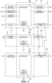
- Fig. 4 illustrates an example of the system configuration of the robotic working apparatus 1.
- the controller 10A of the working robot 10 transmits and receives information via the communication part 17 as described above, and a controller (CPU) 30A of the management device 30 transmits and receives information via the communication part 31.
- a controller (CPU) 20A of the base 20 transmits and receives information via the communication part 21.
- the controllers 10A, 20A and 30A include timers 50, 51, and 52 such as real-time clocks configured to measure and output the time, and memories 60, 61, and 62 configured to store information and programs, respectively.
- the controllers 10A, 20A, and 30A constitute a controller U which is unified by the exchange of information among the communication parts 17, 21, and 31, and the functions of the controllers 10A, 20A and 30A can be substituted for each other.
- the controller 10A of the working robot 10 receives work instruction information (the existing work schedule, the working area, and the traveling route) from a setting input part 19, receives information from a working state detector 10T, receives information about the current position of the working robot 10 from the position detector 16, and receives information about the remaining amount of the battery from the battery 14. Then, the controller 10A controls the traveling drive part 11A and the working drive part 12A based on the inputted information, and performs the work of the working robot 10 according to the inputted work instruction information.
- work instruction information the existing work schedule, the working area, and the traveling route
- the working state detector 10T When the working tool 12 is the blade device 12S, the working state detector 10T is configured to detect the drive state of the load on a blade. Meanwhile, when the working tool 12 is the collection device 12P, the working state detector 10T is configured to detect the information about the amount of the collected target objects O from the measurement part 15.
- the controller 20A provided in the base 20 receives charging process information and so forth from the charging device 22 charging the battery 14 of the working robot 10.
- the controller 30A of the management device 30 receives work instruction information (the work schedule, the working area, and the traveling route) and management facility information (business hours, users, use places, the state of the field F, information about the growth of plants on the field F, the amount of feed of the target objects O, events of the management facility, and event times) from a setting input part 34.
- work instruction information the work schedule, the working area, and the traveling route
- management facility information business hours, users, use places, the state of the field F, information about the growth of plants on the field F, the amount of feed of the target objects O, events of the management facility, and event times
- the controller U (10A, 20A, and 30A) of the robotic working apparatus 1 includes a traveling motion controller P1 to control the autonomous travel of the traveling part 11 (traveling drive part 11A), a working motion controller P2 to control the motion of the working tool 12 (working drive part 12A), and a setting controller P3 to set the traveling route of the working robot 10.
- the traveling motion controller P1, the working motion controller P2 and the setting controller P3 are programs to control the operation of the CPU of the controller U (10A, 20A, and 30A).
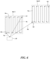
- a first area Wa(1) and a second area Wa(2) are set as a plurality of working areas, and traveling routes for the working robots 10 are set to move from a work end point G1 in the first area Wa(1) to a work start point G2 in the second area Wa(2).
- a traveling route to move from the work end point G1 in the first area Wa(1) directly to the work start point G2 in the second area Wa(2) is not set, but a traveling route from the work end point G1 to the base 20, and a traveling route from the base 20 to the work start point G2 are set.
- the traveling route from the work end point G1 to the base 20 is set to be different at least in part from the traveling route from the base 20 to the work start point G2.
- each of the traveling route from the work end point G1 to the base 20 and the traveling route from the base 20 to the work start point G2 may be a straight route or a non-straight route.
- each of the traveling route from the work end point G1 to the base 20 and the traveling route from the base 20 to the work start point G2 may be a direct route or a route with a relay point.
- a traveling route Rw for work is set in each of the first area Wa(1) and the second area Wa(2).
- the traveling routes Rw are set for patterned traveling, and with the illustrated example, are formed in a stripe pattern in which straight and parallel lines are alternately inversed.
- the traveling route Rw in the first area Wa(1) is a route from a work start point G0 to the work end point G1.
- the traveling route Rw in the second area Wa(2) is a route from the work start point G2 to a work end point G3.
- a traveling route Rs from the base 20 to the work start point G0 in the first area Wa(1), a traveling route Rt from the work end point G1 in the first area Wa(1) to the base 20, and a traveling route Rd from the base 20 to the work start point G2 in the second area Wa(2) are set not to overlap each other.
- each of the traveling routes Rs, Rt, and Rd is a direct and straight route.
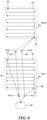
- a relay point Pr is provided in the traveling route Rd.
- the relay point Pr when an avoidance area Av to avoid an obstacle and so forth is set between the base 20 and the work start point G2 in the second area Wa(2), the relay point Pr is set to provide an alternative route to bypass the avoidance area Av.
- This relay point Pr may be provided between the work end point G1 and the base 20 and/or between the base 20 and the work start point G2, and also provided between the base 20 and the work start point G0 as needed.
- the location accuracy is improved, and therefore when only one relay point is set, the working robot 10 travels and turns intensively at the location of the relay point. This may cause the damage of the field F.
- a plurality of relay points are set, and one of them is randomly selected. By this means, it is possible to prevent the damage of the field F.
- Fig. 8 illustrates an example where a plurality of relay points Pr(1), Pr(2), Pr(3), and Pr(4) are provided.
- the relay point Pr(1) is provided between the base 20 and the work start point G0 in the first area Wa(1);
- the relay point Pr(2) is provided between the work end point G1 in the first area Wa(1) and the base 20;
- the relay point Pr(3) and the relay point Pr(4) are provided between the base 20 and the work start point G2 in the second area Wa(2).
- these relay points are appropriately selected.
- At least one of the work start point G0 in the first area Wa(1), the work end point G1 in the first area Wa(1), and the work start point G2 in the second area Wa(2) is different from that set in the past.
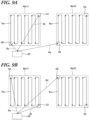
- Figs. 10A and 10B illustrate an example which is not part of the present invention, where the patterned traveling is set for the first area Wa(1) and the second area Wa(2), and the angle of the patterned traveling set this time is changed from the angle of the patterned traveling set in the past.
- the traveling routes Rw in the first area Wa(1) and the second area Wa(2) set last time or several times ago form the patterned traveling in the stripe pattern along Y direction as illustrated in Fig. 10A
- the patterned traveling of the traveling routes Rw in the first area Wa(1) and the second area Wa(2) are changed to that in the stripe pattern along X direction as illustrated in Fig. 10B this time. In this way, the angle of the patterned traveling is changed.
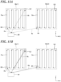
- Figs. 11A and 11B illustrate an example which is not part of the present invention, where the work end point G1 in the first area Wa(1) and the work start point G2 in the second area Wa(2) set this time are shifted from those set in the past, respectively. That is, in a case where the work end point G1 in the first area Wa(1) and the work start point G2 in the second area Wa(2) are set as illustrated in Fig. 11A last time or several times ago, each of the work end point G1 and the work start point G2 is shifted in the Y direction by a predetermined distance as illustrated in Fig. 11B this time. By this means, it is possible to prevent the traveling routes Rt and Rd set this time from overlapping with the traveling routes Rt and Rd set last time, respectively.
- the shifted points may be the work start point G0 in the first area Wa(1) and the work end point G3 in the second area Wa(2), and any point may be selected.
- the direction to shift the point may be the X direction, and any direction may be selected.
- the work end point G1 in the first area Wa(1) and the work start point G2 in the second area Wa(2) are set to be different from one another.
- the work end point G1 in the first area Wa(1) and the work start point G2 in the second area Wa(2) may be set to the same point.
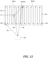
- the relay point Pr is set as illustrated in Fig. 12 , and therefore it is possible to prevent the traveling route Rd from overlapping with the traveling route Rt.
- the work end point G1 in the first area Wa(1), the work start point G2 in the second area Wa(2), and the base 20 may be arranged linearly (the work start point G2 is located on the extended line of the line connecting the base 20 to the work end point G1).
- the relay point Pr is set as illustrated in Fig. 13 , and therefore it is possible to prevent the traveling route Rd from overlapping with the traveling route Rt.
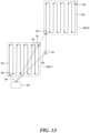
- a space area Sa may be provided between the first area Wa(1) and the second area Wa(2).
- the relay point Pr is set as illustrated in Fig. 14 .
- the traveling route from the base 20 to the work start point G2 in the second area Wa(2) is a route obtained by adding the traveling route Rd2 to the traveling route Rd1.
- the working tool 12 of the working robot 10 is actuated and working on the traveling routes Rw in the first area Wa(1) and the second area Wa(2).
- the working tool 12 is the blade device 12S
- the mowing work is performed along the traveling routes Rw.
- the working tool 12 is the collection device 12P, the collection work to collect the target objects O is performed along the traveling routes Rw.
- the working tool 12 does not work on traveling routes Rt and Rd set when the working robot 10 moves from the work end point G1 in the first area Wa(1) to the work start point G2 in the second area Wa(2), or the traveling route Rs from the base 20 to the work start point G0 in the first area Wa(1).
- the working tool 12 does not work, and therefore it is possible to prevent wasteful consumption of the battery and also prevent the life of the working tool 12 from being reduced.
Landscapes
- Engineering & Computer Science (AREA)
- Aviation & Aerospace Engineering (AREA)
- Radar, Positioning & Navigation (AREA)
- Remote Sensing (AREA)
- Physics & Mathematics (AREA)
- General Physics & Mathematics (AREA)
- Automation & Control Theory (AREA)
- Life Sciences & Earth Sciences (AREA)
- Environmental Sciences (AREA)
- Control Of Position, Course, Altitude, Or Attitude Of Moving Bodies (AREA)
- Guiding Agricultural Machines (AREA)
Claims (7)
- Appareil de travail robotique (1) comprenant :un robot de travail (10) ayant un outil de travail (12) configuré pour effectuer un travail sur un champ (F), ledit robot de travail étant configuré pour effectuer le travail avec l'outil de travail (12) tout en se déplaçant de manière autonome sur le champ (F) ; etun contrôleur (10A, 20A, 30A, U) configuré pour définir une route itinérante (Rw, Rs, Rt, Rd, Rd1, Rd2) pour le robot de travail (10) et commander le mouvement du robot de travail (10), dans lequel :une première zone (Wa(1)) et une seconde zone (Wa(2)) sont définies sur le champ (F) en tant que zones de travail du robot de travail (10), lorsque le robot de travail (10) se déplace d'un point final du travail (G1) dans la première zone (Wa(1)) à un point de départ du travail (G2) dans la seconde zone (Wa(2)), le contrôleur (10A, 20A, 30A, U) définit une route (Rt) du point final du travail (G1) à une base (20), et une route (Rd) de la base (20) au point de départ du travail (G2) ; etla route (Rt) du point final du travail (G1) à la base (20) est différente au moins en partie de la route (Rd) de la base (20) au point de départ du travail (G2),caractérisé en ce queun point de relais (Pr(2), Pr(3), Pr(4)) est sélectionné parmi une pluralité de points de relais (Pr(2), Pr(3), Pr(4)) etla route (Rd) entre la base (20) et le point de départ du travail (G2) dans la seconde zone (Wa(2)) consiste en une ligne droite de la base (20) au point de relais sélectionné (Pr(2), Pr(3), Pr(4)) et une ligne droite du point de relais sélectionné (Pr(2), Pr(3), Pr(4)) au point de départ du travail (G2) dans la seconde zone (Wa(2)), et/oula route (Rt) entre le point final du travail (G1) dans la première zone (Wa(1)) et la base (20) consiste en une ligne droite du point final du travail (G1) dans la première zone (Wa(1)) au point de relais sélectionné (Pr(2), Pr(3), Pr(4)) et une ligne droite du point de relais sélectionné (Pr(2), Pr(3), Pr(4)) à la base (20).
- Appareil de travail robotique (1) selon la revendication 1, dans lequel la base (20) est une base de chargement pour le robot de travail (10).
- Appareil de travail robotique (1) selon la revendication 1 ou 2, dans lequel le point final du travail (G1) dans la première zone (Wa(1)) et le point de départ du travail (G2) dans la seconde zone (Wa(2)) sont différents l'un de l'autre.
- Appareil de travail robotique (1) selon l'une des revendications 1 à 3, dans lequel, lorsque le robot de travail (10) se déplace du point final du travail (G1) dans la première zone (Wa(1)) au point de départ du travail (G2) dans la seconde zone (Wa(2)), l'outil de travail (12) ne fonctionne pas.
- Appareil de travail robotique (1) selon l'une des revendications 1 à 4, dans lequel l'outil de travail (12) est un dispositif de lame (12S) pour effectuer un fondement sur le champ (F).
- Appareil de travail robotique (1) selon l'une des revendications 1 à 4, dans lequel l'outil de travail (12) est un dispositif de collection (12P) configuré pour collecter des objets cibles sur le champ (F).
- Appareil de travail robotique (1) selon l'une des revendications 1 à 6, dans lequel une zone spatiale est prévue entre la première zone (Wa(1)) et la seconde zone (Wa(2)).
Applications Claiming Priority (1)
| Application Number | Priority Date | Filing Date | Title |
|---|---|---|---|
| JP2021074975A JP7649192B2 (ja) | 2021-04-27 | 2021-04-27 | ロボット作業装置 |
Publications (2)
| Publication Number | Publication Date |
|---|---|
| EP4083742A1 EP4083742A1 (fr) | 2022-11-02 |
| EP4083742B1 true EP4083742B1 (fr) | 2024-11-27 |
Family
ID=81654686
Family Applications (1)
| Application Number | Title | Priority Date | Filing Date |
|---|---|---|---|
| EP22169814.5A Active EP4083742B1 (fr) | 2021-04-27 | 2022-04-25 | Appareil de travail robotisé |
Country Status (3)
| Country | Link |
|---|---|
| US (1) | US12575486B2 (fr) |
| EP (1) | EP4083742B1 (fr) |
| JP (1) | JP7649192B2 (fr) |
Families Citing this family (1)
| Publication number | Priority date | Publication date | Assignee | Title |
|---|---|---|---|---|
| JP7353877B2 (ja) * | 2019-09-06 | 2023-10-02 | 株式会社クボタ | 作業車両及び作業車両の作業支援装置 |
Family Cites Families (12)
| Publication number | Priority date | Publication date | Assignee | Title |
|---|---|---|---|---|
| JPH07203706A (ja) * | 1994-01-20 | 1995-08-08 | Fuji Heavy Ind Ltd | 自律走行作業車 |
| DE102011083309A1 (de) | 2011-09-23 | 2013-03-28 | Robert Bosch Gmbh | Autonomes Arbeitsgerät |
| DE102014226084A1 (de) | 2014-12-16 | 2016-06-16 | Robert Bosch Gmbh | Verfahren zur Kartierung einer Bearbeitungsfläche für autonome Roboterfahrzeuge |
| US9538702B2 (en) | 2014-12-22 | 2017-01-10 | Irobot Corporation | Robotic mowing of separated lawn areas |
| JP5973608B1 (ja) | 2015-03-27 | 2016-08-23 | 本田技研工業株式会社 | 無人作業車の制御装置 |
| JP6014192B1 (ja) | 2015-03-27 | 2016-10-25 | 本田技研工業株式会社 | 無人作業車の制御装置 |
| JP5917747B1 (ja) | 2015-04-28 | 2016-05-18 | シャープ株式会社 | 自律型作業車 |
| US10168709B2 (en) * | 2016-09-14 | 2019-01-01 | Irobot Corporation | Systems and methods for configurable operation of a robot based on area classification |
| EP4276645A3 (fr) * | 2016-12-15 | 2024-01-10 | Positec Power Tools (Suzhou) Co., Ltd. | Méthode de détection d'état pour système de travail automatique et station mobile |
| JP6997293B2 (ja) | 2018-03-30 | 2022-01-17 | 本田技研工業株式会社 | 自律走行作業機、及び制御システム |
| WO2019194636A1 (fr) * | 2018-04-06 | 2019-10-10 | 엘지전자 주식회사 | Robot mobile et procédé de commande du robot mobile |
| US11944032B2 (en) * | 2019-09-23 | 2024-04-02 | Renu Robotics Corporation | Autonomous vehicle systems and methods |
-
2021
- 2021-04-27 JP JP2021074975A patent/JP7649192B2/ja active Active
-
2022
- 2022-04-11 US US17/717,798 patent/US12575486B2/en active Active
- 2022-04-25 EP EP22169814.5A patent/EP4083742B1/fr active Active
Also Published As
| Publication number | Publication date |
|---|---|
| JP7649192B2 (ja) | 2025-03-19 |
| US20220338409A1 (en) | 2022-10-27 |
| US12575486B2 (en) | 2026-03-17 |
| JP2022169128A (ja) | 2022-11-09 |
| EP4083742A1 (fr) | 2022-11-02 |
Similar Documents
| Publication | Publication Date | Title |
|---|---|---|
| US11841710B2 (en) | Automatic working system, self-moving device, and methods for controlling same | |
| US12061476B2 (en) | Returning method of self-moving device, self-moving device, storage medium, and server | |
| CN108227705B (zh) | 自移动设备的回归方法、自移动设备、存储介质和服务器 | |
| KR20200096489A (ko) | 작업차, 작업차를 위한 주행 경로 선택 시스템, 및 주행 경로 산출 시스템 | |
| EP3084542B1 (fr) | Système et procédé permettant la navigation d'un outil de travail robotique | |
| EP4037464B1 (fr) | Système d'outil de travail robotique et procédé de transport d'un outil de travail robotique entre différentes zones | |
| EP4179862B1 (fr) | Tondeuses à gazon robotiques | |
| US20140324246A1 (en) | Autonomous working device | |
| JPWO2020110247A1 (ja) | 制御システム、制御装置、自律作業機、制御装置の動作方法、自律作業機の制御方法及びプログラム | |
| CN102597898A (zh) | 场地中的车辆移动协调 | |
| EP4083737A1 (fr) | Procédé et système de traversée, robot et support d'informations lisible | |
| US20240049627A1 (en) | Improved operation for a robotic work tool | |
| EP4083742B1 (fr) | Appareil de travail robotisé | |
| HK40081540B (en) | Robotic working apparatus | |
| HK40081540A (en) | Robotic working apparatus | |
| US12547187B2 (en) | Work management system | |
| EP4372511B1 (fr) | Système et procédé de commande de multiples tondeuses robotiques | |
| EP3696640B1 (fr) | Véhicule robotisé pour fonctionnement mobile dans une zone de travail | |
| US20220326686A1 (en) | Robotic collection system | |
| US12356887B2 (en) | Working robot and control method | |
| EP4371390A1 (fr) | Système et procédé de commande d'au moins un robot de tonte | |
| EP4098097B1 (fr) | Système de maintenance terrestre, en particulier configuré pour déterminer le niveau de charge d'une batterie d'un dispositif mobile par rapport à un cycle de travail | |
| US12487604B2 (en) | Navigation for a robotic work tool system | |
| HK40078748A (en) | Robotic collection system | |
| WO2022244143A1 (fr) | Appareil de travail robotisé |
Legal Events
| Date | Code | Title | Description |
|---|---|---|---|
| PUAI | Public reference made under article 153(3) epc to a published international application that has entered the european phase |
Free format text: ORIGINAL CODE: 0009012 |
|
| STAA | Information on the status of an ep patent application or granted ep patent |
Free format text: STATUS: THE APPLICATION HAS BEEN PUBLISHED |
|
| AK | Designated contracting states |
Kind code of ref document: A1 Designated state(s): AL AT BE BG CH CY CZ DE DK EE ES FI FR GB GR HR HU IE IS IT LI LT LU LV MC MK MT NL NO PL PT RO RS SE SI SK SM TR |
|
| STAA | Information on the status of an ep patent application or granted ep patent |
Free format text: STATUS: REQUEST FOR EXAMINATION WAS MADE |
|
| REG | Reference to a national code |
Ref country code: HK Ref legal event code: DE Ref document number: 40081540 Country of ref document: HK |
|
| 17P | Request for examination filed |
Effective date: 20230502 |
|
| RBV | Designated contracting states (corrected) |
Designated state(s): AL AT BE BG CH CY CZ DE DK EE ES FI FR GB GR HR HU IE IS IT LI LT LU LV MC MK MT NL NO PL PT RO RS SE SI SK SM TR |
|
| STAA | Information on the status of an ep patent application or granted ep patent |
Free format text: STATUS: EXAMINATION IS IN PROGRESS |
|
| 17Q | First examination report despatched |
Effective date: 20230913 |
|
| REG | Reference to a national code |
Ref country code: DE Ref legal event code: R079 Free format text: PREVIOUS MAIN CLASS: G05D0001020000 Ipc: G05D0001000000 Ref country code: DE Ref legal event code: R079 Ref document number: 602022008070 Country of ref document: DE Free format text: PREVIOUS MAIN CLASS: G05D0001020000 Ipc: G05D0001000000 |
|
| RIC1 | Information provided on ipc code assigned before grant |
Ipc: G05D 1/00 20060101AFI20240409BHEP |
|
| GRAP | Despatch of communication of intention to grant a patent |
Free format text: ORIGINAL CODE: EPIDOSNIGR1 |
|
| STAA | Information on the status of an ep patent application or granted ep patent |
Free format text: STATUS: GRANT OF PATENT IS INTENDED |
|
| INTG | Intention to grant announced |
Effective date: 20240521 |
|
| GRAS | Grant fee paid |
Free format text: ORIGINAL CODE: EPIDOSNIGR3 |
|
| GRAA | (expected) grant |
Free format text: ORIGINAL CODE: 0009210 |
|
| STAA | Information on the status of an ep patent application or granted ep patent |
Free format text: STATUS: THE PATENT HAS BEEN GRANTED |
|
| AK | Designated contracting states |
Kind code of ref document: B1 Designated state(s): AL AT BE BG CH CY CZ DE DK EE ES FI FR GB GR HR HU IE IS IT LI LT LU LV MC MK MT NL NO PL PT RO RS SE SI SK SM TR |
|
| REG | Reference to a national code |
Ref country code: GB Ref legal event code: FG4D |
|
| REG | Reference to a national code |
Ref country code: CH Ref legal event code: EP |
|
| REG | Reference to a national code |
Ref country code: IE Ref legal event code: FG4D |
|
| REG | Reference to a national code |
Ref country code: DE Ref legal event code: R096 Ref document number: 602022008070 Country of ref document: DE |
|
| REG | Reference to a national code |
Ref country code: LT Ref legal event code: MG9D |
|
| REG | Reference to a national code |
Ref country code: NL Ref legal event code: MP Effective date: 20241127 |
|
| PG25 | Lapsed in a contracting state [announced via postgrant information from national office to epo] |
Ref country code: IS Free format text: LAPSE BECAUSE OF FAILURE TO SUBMIT A TRANSLATION OF THE DESCRIPTION OR TO PAY THE FEE WITHIN THE PRESCRIBED TIME-LIMIT Effective date: 20250327 Ref country code: PT Free format text: LAPSE BECAUSE OF FAILURE TO SUBMIT A TRANSLATION OF THE DESCRIPTION OR TO PAY THE FEE WITHIN THE PRESCRIBED TIME-LIMIT Effective date: 20250327 Ref country code: HR Free format text: LAPSE BECAUSE OF FAILURE TO SUBMIT A TRANSLATION OF THE DESCRIPTION OR TO PAY THE FEE WITHIN THE PRESCRIBED TIME-LIMIT Effective date: 20241127 |
|
| PG25 | Lapsed in a contracting state [announced via postgrant information from national office to epo] |
Ref country code: NL Free format text: LAPSE BECAUSE OF FAILURE TO SUBMIT A TRANSLATION OF THE DESCRIPTION OR TO PAY THE FEE WITHIN THE PRESCRIBED TIME-LIMIT Effective date: 20241127 Ref country code: FI Free format text: LAPSE BECAUSE OF FAILURE TO SUBMIT A TRANSLATION OF THE DESCRIPTION OR TO PAY THE FEE WITHIN THE PRESCRIBED TIME-LIMIT Effective date: 20241127 |
|
| REG | Reference to a national code |
Ref country code: AT Ref legal event code: MK05 Ref document number: 1746275 Country of ref document: AT Kind code of ref document: T Effective date: 20241127 |
|
| PG25 | Lapsed in a contracting state [announced via postgrant information from national office to epo] |
Ref country code: BG Free format text: LAPSE BECAUSE OF FAILURE TO SUBMIT A TRANSLATION OF THE DESCRIPTION OR TO PAY THE FEE WITHIN THE PRESCRIBED TIME-LIMIT Effective date: 20241127 |
|
| PG25 | Lapsed in a contracting state [announced via postgrant information from national office to epo] |
Ref country code: ES Free format text: LAPSE BECAUSE OF FAILURE TO SUBMIT A TRANSLATION OF THE DESCRIPTION OR TO PAY THE FEE WITHIN THE PRESCRIBED TIME-LIMIT Effective date: 20241127 |
|
| PG25 | Lapsed in a contracting state [announced via postgrant information from national office to epo] |
Ref country code: NO Free format text: LAPSE BECAUSE OF FAILURE TO SUBMIT A TRANSLATION OF THE DESCRIPTION OR TO PAY THE FEE WITHIN THE PRESCRIBED TIME-LIMIT Effective date: 20250227 |
|
| PG25 | Lapsed in a contracting state [announced via postgrant information from national office to epo] |
Ref country code: LV Free format text: LAPSE BECAUSE OF FAILURE TO SUBMIT A TRANSLATION OF THE DESCRIPTION OR TO PAY THE FEE WITHIN THE PRESCRIBED TIME-LIMIT Effective date: 20241127 Ref country code: AT Free format text: LAPSE BECAUSE OF FAILURE TO SUBMIT A TRANSLATION OF THE DESCRIPTION OR TO PAY THE FEE WITHIN THE PRESCRIBED TIME-LIMIT Effective date: 20241127 Ref country code: GR Free format text: LAPSE BECAUSE OF FAILURE TO SUBMIT A TRANSLATION OF THE DESCRIPTION OR TO PAY THE FEE WITHIN THE PRESCRIBED TIME-LIMIT Effective date: 20250228 |
|
| PG25 | Lapsed in a contracting state [announced via postgrant information from national office to epo] |
Ref country code: PL Free format text: LAPSE BECAUSE OF FAILURE TO SUBMIT A TRANSLATION OF THE DESCRIPTION OR TO PAY THE FEE WITHIN THE PRESCRIBED TIME-LIMIT Effective date: 20241127 |
|
| PG25 | Lapsed in a contracting state [announced via postgrant information from national office to epo] |
Ref country code: RS Free format text: LAPSE BECAUSE OF FAILURE TO SUBMIT A TRANSLATION OF THE DESCRIPTION OR TO PAY THE FEE WITHIN THE PRESCRIBED TIME-LIMIT Effective date: 20250227 |
|
| PG25 | Lapsed in a contracting state [announced via postgrant information from national office to epo] |
Ref country code: SM Free format text: LAPSE BECAUSE OF FAILURE TO SUBMIT A TRANSLATION OF THE DESCRIPTION OR TO PAY THE FEE WITHIN THE PRESCRIBED TIME-LIMIT Effective date: 20241127 |
|
| PGFP | Annual fee paid to national office [announced via postgrant information from national office to epo] |
Ref country code: DE Payment date: 20250318 Year of fee payment: 4 |
|
| PG25 | Lapsed in a contracting state [announced via postgrant information from national office to epo] |
Ref country code: DK Free format text: LAPSE BECAUSE OF FAILURE TO SUBMIT A TRANSLATION OF THE DESCRIPTION OR TO PAY THE FEE WITHIN THE PRESCRIBED TIME-LIMIT Effective date: 20241127 |
|
| PGFP | Annual fee paid to national office [announced via postgrant information from national office to epo] |
Ref country code: BE Payment date: 20250426 Year of fee payment: 4 |
|
| PG25 | Lapsed in a contracting state [announced via postgrant information from national office to epo] |
Ref country code: EE Free format text: LAPSE BECAUSE OF FAILURE TO SUBMIT A TRANSLATION OF THE DESCRIPTION OR TO PAY THE FEE WITHIN THE PRESCRIBED TIME-LIMIT Effective date: 20241127 |
|
| PGFP | Annual fee paid to national office [announced via postgrant information from national office to epo] |
Ref country code: FR Payment date: 20250426 Year of fee payment: 4 |
|
| PG25 | Lapsed in a contracting state [announced via postgrant information from national office to epo] |
Ref country code: RO Free format text: LAPSE BECAUSE OF FAILURE TO SUBMIT A TRANSLATION OF THE DESCRIPTION OR TO PAY THE FEE WITHIN THE PRESCRIBED TIME-LIMIT Effective date: 20241127 |
|
| PG25 | Lapsed in a contracting state [announced via postgrant information from national office to epo] |
Ref country code: SK Free format text: LAPSE BECAUSE OF FAILURE TO SUBMIT A TRANSLATION OF THE DESCRIPTION OR TO PAY THE FEE WITHIN THE PRESCRIBED TIME-LIMIT Effective date: 20241127 |
|
| PG25 | Lapsed in a contracting state [announced via postgrant information from national office to epo] |
Ref country code: CZ Free format text: LAPSE BECAUSE OF FAILURE TO SUBMIT A TRANSLATION OF THE DESCRIPTION OR TO PAY THE FEE WITHIN THE PRESCRIBED TIME-LIMIT Effective date: 20241127 |
|
| PG25 | Lapsed in a contracting state [announced via postgrant information from national office to epo] |
Ref country code: IT Free format text: LAPSE BECAUSE OF FAILURE TO SUBMIT A TRANSLATION OF THE DESCRIPTION OR TO PAY THE FEE WITHIN THE PRESCRIBED TIME-LIMIT Effective date: 20241127 |
|
| REG | Reference to a national code |
Ref country code: DE Ref legal event code: R097 Ref document number: 602022008070 Country of ref document: DE |
|
| PG25 | Lapsed in a contracting state [announced via postgrant information from national office to epo] |
Ref country code: SE Free format text: LAPSE BECAUSE OF FAILURE TO SUBMIT A TRANSLATION OF THE DESCRIPTION OR TO PAY THE FEE WITHIN THE PRESCRIBED TIME-LIMIT Effective date: 20241127 |
|
| PLBE | No opposition filed within time limit |
Free format text: ORIGINAL CODE: 0009261 |
|
| STAA | Information on the status of an ep patent application or granted ep patent |
Free format text: STATUS: NO OPPOSITION FILED WITHIN TIME LIMIT |
|
| REG | Reference to a national code |
Ref country code: CH Ref legal event code: L10 Free format text: ST27 STATUS EVENT CODE: U-0-0-L10-L00 (AS PROVIDED BY THE NATIONAL OFFICE) Effective date: 20251008 |
|
| 26N | No opposition filed |
Effective date: 20250828 |
|
| REG | Reference to a national code |
Ref country code: CH Ref legal event code: H13 Free format text: ST27 STATUS EVENT CODE: U-0-0-H10-H13 (AS PROVIDED BY THE NATIONAL OFFICE) Effective date: 20251125 |
|
| PG25 | Lapsed in a contracting state [announced via postgrant information from national office to epo] |
Ref country code: LU Free format text: LAPSE BECAUSE OF NON-PAYMENT OF DUE FEES Effective date: 20250425 |
|
| PG25 | Lapsed in a contracting state [announced via postgrant information from national office to epo] |
Ref country code: MC Free format text: LAPSE BECAUSE OF FAILURE TO SUBMIT A TRANSLATION OF THE DESCRIPTION OR TO PAY THE FEE WITHIN THE PRESCRIBED TIME-LIMIT Effective date: 20241127 |
|
| PG25 | Lapsed in a contracting state [announced via postgrant information from national office to epo] |
Ref country code: CH Free format text: LAPSE BECAUSE OF NON-PAYMENT OF DUE FEES Effective date: 20250430 |
|
| PG25 | Lapsed in a contracting state [announced via postgrant information from national office to epo] |
Ref country code: IE Free format text: LAPSE BECAUSE OF NON-PAYMENT OF DUE FEES Effective date: 20250425 |