EP4086418A1 - Système comprenant un meuble doté d'une niche intégrée et d'un appareil intégré, et procédé de fonctionnement du système - Google Patents
Système comprenant un meuble doté d'une niche intégrée et d'un appareil intégré, et procédé de fonctionnement du système Download PDFInfo
- Publication number
- EP4086418A1 EP4086418A1 EP22166714.0A EP22166714A EP4086418A1 EP 4086418 A1 EP4086418 A1 EP 4086418A1 EP 22166714 A EP22166714 A EP 22166714A EP 4086418 A1 EP4086418 A1 EP 4086418A1
- Authority
- EP
- European Patent Office
- Prior art keywords
- built
- furniture
- furniture door
- longitudinal guides
- niche
- Prior art date
- Legal status (The legal status is an assumption and is not a legal conclusion. Google has not performed a legal analysis and makes no representation as to the accuracy of the status listed.)
- Granted
Links
Images


Classifications
-
- E—FIXED CONSTRUCTIONS
- E05—LOCKS; KEYS; WINDOW OR DOOR FITTINGS; SAFES
- E05D—HINGES OR SUSPENSION DEVICES FOR DOORS, WINDOWS OR WINGS
- E05D15/00—Suspension arrangements for wings
- E05D15/56—Suspension arrangements for wings with successive different movements
- E05D15/58—Suspension arrangements for wings with successive different movements with both swinging and sliding movements
-
- F—MECHANICAL ENGINEERING; LIGHTING; HEATING; WEAPONS; BLASTING
- F24—HEATING; RANGES; VENTILATING
- F24C—DOMESTIC STOVES OR RANGES ; DETAILS OF DOMESTIC STOVES OR RANGES, OF GENERAL APPLICATION
- F24C15/00—Details
- F24C15/02—Doors specially adapted for stoves or ranges
- F24C15/026—Doors specially adapted for stoves or ranges stowing of door in open position
-
- E—FIXED CONSTRUCTIONS
- E05—LOCKS; KEYS; WINDOW OR DOOR FITTINGS; SAFES
- E05Y—INDEXING SCHEME ASSOCIATED WITH SUBCLASSES E05D AND E05F, RELATING TO CONSTRUCTION ELEMENTS, ELECTRIC CONTROL, POWER SUPPLY, POWER SIGNAL OR TRANSMISSION, USER INTERFACES, MOUNTING OR COUPLING, DETAILS, ACCESSORIES, AUXILIARY OPERATIONS NOT OTHERWISE PROVIDED FOR, APPLICATION THEREOF
- E05Y2900/00—Application of doors, windows, wings or fittings thereof
- E05Y2900/20—Application of doors, windows, wings or fittings thereof for furniture, e.g. cabinets
- E05Y2900/212—Doors disappearing in pockets in the furniture body
-
- E—FIXED CONSTRUCTIONS
- E05—LOCKS; KEYS; WINDOW OR DOOR FITTINGS; SAFES
- E05Y—INDEXING SCHEME ASSOCIATED WITH SUBCLASSES E05D AND E05F, RELATING TO CONSTRUCTION ELEMENTS, ELECTRIC CONTROL, POWER SUPPLY, POWER SIGNAL OR TRANSMISSION, USER INTERFACES, MOUNTING OR COUPLING, DETAILS, ACCESSORIES, AUXILIARY OPERATIONS NOT OTHERWISE PROVIDED FOR, APPLICATION THEREOF
- E05Y2900/00—Application of doors, windows, wings or fittings thereof
- E05Y2900/30—Application of doors, windows, wings or fittings thereof for domestic appliances
- E05Y2900/302—Application of doors, windows, wings or fittings thereof for domestic appliances for built-in appliances
-
- E—FIXED CONSTRUCTIONS
- E05—LOCKS; KEYS; WINDOW OR DOOR FITTINGS; SAFES
- E05Y—INDEXING SCHEME ASSOCIATED WITH SUBCLASSES E05D AND E05F, RELATING TO CONSTRUCTION ELEMENTS, ELECTRIC CONTROL, POWER SUPPLY, POWER SIGNAL OR TRANSMISSION, USER INTERFACES, MOUNTING OR COUPLING, DETAILS, ACCESSORIES, AUXILIARY OPERATIONS NOT OTHERWISE PROVIDED FOR, APPLICATION THEREOF
- E05Y2900/00—Application of doors, windows, wings or fittings thereof
- E05Y2900/30—Application of doors, windows, wings or fittings thereof for domestic appliances
- E05Y2900/308—Application of doors, windows, wings or fittings thereof for domestic appliances for ovens
-
- F—MECHANICAL ENGINEERING; LIGHTING; HEATING; WEAPONS; BLASTING
- F24—HEATING; RANGES; VENTILATING
- F24C—DOMESTIC STOVES OR RANGES ; DETAILS OF DOMESTIC STOVES OR RANGES, OF GENERAL APPLICATION
- F24C15/00—Details
- F24C15/02—Doors specially adapted for stoves or ranges
- F24C15/023—Mounting of doors, e.g. hinges, counterbalancing
-
- F—MECHANICAL ENGINEERING; LIGHTING; HEATING; WEAPONS; BLASTING
- F24—HEATING; RANGES; VENTILATING
- F24C—DOMESTIC STOVES OR RANGES ; DETAILS OF DOMESTIC STOVES OR RANGES, OF GENERAL APPLICATION
- F24C15/00—Details
- F24C15/02—Doors specially adapted for stoves or ranges
- F24C15/027—Doors specially adapted for stoves or ranges located at bottom side of housing
Definitions
- the invention relates to a system comprising a piece of furniture with a built-in niche and a built-in device of the type mentioned in the preamble of patent claim 1 and a method for operating the system.
- the known systems include, for example, a piece of furniture with a built-in niche formed in a furniture body of the piece of furniture with a built-in niche opening, a built-in appliance for preparing food arranged in the built-in niche, and a stowage device with a stowage space arranged under the built-in appliance in the built-in niche and a stowage mechanism, with the built-in device arranged in the built-in niche is inaccessible by means of a furniture door of the piece of furniture when the furniture door is in a closed position that covers the built-in niche and is accessible when the furniture door is in an open position, and wherein the stowage space is designed to accommodate the furniture door in its open position and the stowage mechanism is used on the one hand to transfer the Furniture door is formed from its closed position into its open position and from its open position into its closed position and on the other hand on the furniture body and/or
- the invention therefore addresses the problem of improving a system, comprising a piece of furniture with a built-in niche and a built-in appliance, and a method for operating the system.
- this problem is solved by a system having the features of patent claim 1, which is characterized in that at least two of the longitudinal guides correspond to one another and are held on opposite sides of the furniture door such that they can be moved or automatically moved on the furniture body and/or the built-in device such that the furniture door can be moved back and forth between its closed position and its open position relative to the furniture body and the built-in appliance without collision. Furthermore, this problem is solved by a method having the features of patent claim 10 .
- the built-in appliance for preparing food can be used, for example, as an oven, a microwave oven, a steam cooker, a combination cooking appliance with a plurality of different types of heating or be a coffee machine.
- the built-in appliance can be in the form of a household appliance or a commercial appliance, ie a built-in appliance for professional use.
- the advantage that can be achieved with the invention is, in particular, that a system comprising a piece of furniture with a built-in niche and a built-in device and a method for operating the system are improved. Due to the design of the system and the method according to the invention, it is possible for the furniture door to be transferrable back and forth between its closed position and its open position relative to the furniture carcass and the built-in appliance without a collision.
- the longitudinal guides that are movably or automatically movable on the furniture carcass and/or the built-in device enable a pivoting movement of the furniture door when transferring the furniture door from its open position to its closed position or vice versa, almost without the translational movement usually associated with this of a furniture door that can be pivoted about an axis of rotation.
- an undesired collision of the furniture door during its transfer from its open position to its closed position or from its closed position to its open position with the furniture body on the one hand and with the built-in appliance on the other hand is effectively prevented.
- the system can be freely selected in terms of type, function, material and dimensioning within wide, suitable limits.
- the adjustment mechanism is designed in such a way that the longitudinal guides held on the furniture body and/or the built-in appliance can be moved automatically and/or the corresponding guide rollers depending on a closing command and/or opening command applied to the adjustment mechanism Furniture door are automatically movable.
- the user-friendliness of the system according to the invention is significantly increased. Manual operation of the furniture door during its transfer from its closed position to its open position and vice versa is no longer necessary. A user of the system has his hands free for other activities, for example.
- the adjustment mechanism can be controlled by a large number of closing commands and/or opening commands from devices that are different from one another. These devices can be, for example, the built-in device installed in the built-in niche.
- the closing command and/or the opening command can be triggered by the built-in device as a function of a predetermined operating state of the built-in device and/or a predetermined automatic program running in the built-in device. It is also conceivable that the closing command and / or the Opening command to the stowage mechanism by means of a mobile device, such as a smartphone or the like, can be triggered.
- a further advantageous development of the system according to the invention provides that four longitudinal guides are held on the furniture body and/or the built-in device and four guide rollers are held on the furniture door, one of the four guide rollers corresponding to one of the longitudinal guides, and two of the four longitudinal guides each are arranged on both sides of the furniture door in such a way that the two longitudinal guides arranged on one of the two sides are arranged one above the other and spaced apart from one another, preferably that the two guide rollers arranged on one of the two sides are at a constant distance from one another on the furniture door, regardless of the position of the furniture door are arranged, particularly preferred that these guide rollers are each arranged at a constant distance from an inside of the furniture door on the furniture door.
- the system according to the invention in particular the stowage mechanism of the system according to the invention, can be implemented in a manner that is structurally and technically robust and functionally reliable.
- the aforementioned distances between the guide rollers allow a sufficiently long lever arm to absorb a weight of the furniture door acting in the open position of the furniture door, i.e. in its horizontal position, by means of the stowage mechanism without additional aids, such as Teflon gliders or the like.
- an advantageous development of the aforementioned development of the system according to the invention provides that the longitudinal guides arranged at the top on the two sides are designed as the longitudinal guides that are movably or automatically movable on the furniture carcass and/or the built-in device, preferably that only the two aforementioned longitudinal guides as which are designed to be movable or automatically movable on the furniture carcass and/or the built-in device held longitudinal guides.
- the structural and production engineering structure of the system according to the invention is further simplified. This applies in particular to the preferred embodiment of this development.
- the longitudinal guides arranged at the top on the two sides have a horizontally running first section away from the recess opening and a second section running transversely upwards, preferably vertically upwards, towards the first section. wherein the first and the second section are connected to one another by means of a transition section of the respective longitudinal guide in a guide roller-guiding manner.
- the longitudinal guides arranged at the bottom on both sides have a horizontally extending first section away from the recess opening and a horizontally extending first section close to the recess opening and transversely downwards to the first section, preferably in a downward curve. running second section, wherein the first and the second section are connected to one another by means of a transition section of the respective longitudinal guide in a guide roller-guiding manner, preferably that the transition section, starting from the first section, first runs steadily upwards to a vertex and then continuously downwards from the vertex moves to the second section.
- the longitudinal guides arranged at the bottom on both sides of the furniture door are also implemented in a robust and therefore functionally reliable manner according to one of the last three embodiments of the system according to the invention.
- a particularly advantageous development of the system according to the invention provides that the guide rollers are each arranged on the furniture door in such a way that the overall width of the furniture door is constant regardless of the presence of the guide rollers on the furniture door.
- the use of the system according to the invention is also correspondingly simplified, since the system according to the invention, according to this development, is designed to match the standard dimensions usually used for furniture with built-in niches and built-in devices for such built-in niches.
- the system according to the invention is also designed to be suitable for subsequent conversion, ie as a retrofit kit.
- another advantageous development of the system according to the invention provides that the stowage mechanism and the furniture door are designed to be coordinated with one another in such a way that the depth of the installation niche is independent of the presence of the stowage space arranged under the built-in appliance and of the storage space in the open position furniture door arranged in this storage space is designed to be constant.
- the design of the depth of the installation niche is minimized, in particular, the depth of the Built-in niche not or only a few centimeters beyond the size of the furniture door in the open position. It is even possible that a depth of the installation niche that deviates from the usual standard dimensions is not required for the system according to the invention. See also the advantages mentioned for the above-mentioned embodiment of the system according to the invention.
- a further advantageous development of the system according to the invention provides that the stowage mechanism is designed in such a way that the longitudinal guides, which are movably or automatically movable on the furniture carcass and/or the built-in appliance, move horizontally in the direction of the installation niche opening and during the transfer of the furniture door from its open position to its closed position can be moved horizontally in the direction opposite to the direction of the built-in niche opening.
- a simple sequence of movements is realized for the longitudinal guides held movably or automatically on the furniture carcass and/or the built-in appliance, so that these longitudinal guides are realized in a particularly simple manner in terms of design and production technology. Due to the simple sequence of movements, undesired tilting or jamming during the movement of the aforementioned longitudinal guides is effectively prevented, for example, so that the robustness and functional reliability of the system according to the invention are further improved according to this development.
- the direction of the recess opening is defined as from the rear wall of the furniture to the front of the furniture. According to one aspect, the direction of the installation niche opening is oriented orthogonally to the plane of the furniture front or to the plane of the furniture door in the closed position.
- an advantageous development of the method according to the invention provides that the longitudinal guides, which are movably or automatically movable on the furniture carcass and/or the built-in device, move horizontally in the direction of the installation niche opening when the furniture door is transferred from its closed position to its open position and when the furniture door is transferred from its Opening position in the closed position are moved horizontally in the opposite direction to the direction of the installation niche opening.
- a further advantageous development of the method according to the invention provides that the furniture door, when it is being transferred from its closed position to its open position by means of the adjustment mechanism, firstly, in a first movement section of the furniture door by moving the longitudinal guides that are movably or automatically movable on the furniture carcass and/or the built-in device in the direction of the built-in niche opening, pivoted about an axis of rotation of the furniture door and simultaneously lifted upwards and secondly, in a second movement section directly following the first movement section Movement section of the furniture door is pushed horizontally into the storage space by moving the longitudinal guides held on the furniture body and/or the built-in device in a manner opposite to the direction of the built-in niche opening so as to be movable or automatically movable.
- each of the two movement sections can be designed in a previously defined manner for its function, so that the construction of the adjustment mechanism is also significantly simplified as a result.
- the aforementioned movement sections are run through in reverse order.
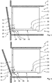
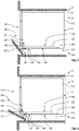
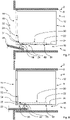
- the system 2 comprises a piece of furniture 4 configured as kitchen furniture with a built-in niche 8 configured in a furniture body 6 of the piece of furniture 4 with a built-in niche opening 10, a built-in appliance 12 for preparing food arranged in the built-in niche 8 and configured as an oven, and a storage device 14 with a lower the built-in device 12 in the niche 8 arranged storage space 16 and a stowage mechanism 18, wherein the arranged in the niche 8 built-in device 12 by means of a furniture door 20 of the furniture 4 in a niche 8 concealing, in the Figures 1 and 2 illustrated closed position of the furniture door 20 inaccessible and in one of the Figures 9 and 10 shown open position of the furniture door 20 is accessible, and the storage space 16 is designed to accommodate the furniture door 20 in its open position.
- the stowage mechanism 18 is designed on the one hand to transfer the furniture door 20 from its closed position to its open position and from its open position to its closed position.
- the stowage mechanism 18 has longitudinal guides 22 , 24 arranged on both sides of the furniture door 20 on the built-in device 12 and rotatable guide rollers 26 , 28 configured correspondingly to the longitudinal guides 22 , 24 on the furniture door 20 .
- the visible longitudinal guides 22, 24 are in the Figures 2 to 10 symbolized by dashed lines.
- the corresponding guide rollers 26, 28 and their holder on the furniture door 20 are in the Figures 2 to 10 also shown in a greatly simplified manner for the sake of clarity.
- the longitudinal guides and guide rollers that are not visible are configured and arranged on the other side of the built-in appliance 12 and the furniture door 20 analogously to the visible longitudinal guides 22 , 24 and guide rollers 26 , 28 .
- two of the longitudinal guides 22, 24, namely the longitudinal guides 22, are held on the built-in appliance 12 so that they correspond to one another and can be moved automatically on opposite sides of the furniture door 20 in such a way that the furniture door 20 can be moved without collision relative to the furniture body 6 and the built-in appliance 12 between its closed position and whose open position can be transferred back and forth.
- the adjusting mechanism 18 is designed here in such a way that the longitudinal guides 22 held on the built-in appliance 12 so that they can move automatically and the corresponding guide rollers 26 can be moved automatically depending on a command to close and/or open the furniture door 20 that is applied to the adjusting mechanism 18.
- four longitudinal guides 22, 24 are held on the built-in appliance 12 and four guide rollers 26, 28 are held on the furniture door 20, one of the four guide rollers 26, 28 corresponding to one of the longitudinal guides 22, 24, and two of the four longitudinal guides 22 , 24 are arranged on both sides of the furniture door 20 in such a way that the two longitudinal guides 22, 24 arranged on one of the two sides are arranged one above the other and at a distance from one another, namely in such a way that the two guide rollers 26, 28 arranged on one of the two sides of the furniture door 20 are arranged at a constant distance from one another on the furniture door 20. Furthermore, these guide rollers 26 , 28 are each arranged on the furniture door 20 at a constant distance from an inside of the furniture door 20 .
- the guide rollers 26, 28 are each arranged on the furniture door 20 in such a way that the overall width of the furniture door 20 is constant regardless of the presence of the guide rollers 26, 28 on the furniture door 20. Accordingly, the overall width of the furniture door 20 does not change due to the presence of the guide rollers 26, 28 compared to the overall width of the furniture door 20 without the guide rollers 26, 28.
- the total width of the furniture door 20 is perpendicular to the image plane 2 .
- longitudinal guides 22 arranged at the top on the two sides are designed as the longitudinal guides 22 held on the built-in device 12 so that they can move automatically.
- These longitudinal guides 22, which are arranged at the top on both sides, have a first section 30 running horizontally away from the recess opening and a second section 32 running transversely upwards to the first section 30, namely vertically upwards, near the recess opening, the first and the second section 30, 32 are connected to each other by means of a transition section 34 of the respective longitudinal guide 22 guiding rollers.
- the longitudinal guides 24 arranged at the bottom on each of the two sides are held immovably, that is to say fixed, on the built-in device 12 .
- These longitudinal guides 24, which are arranged at the bottom on both sides, have a first section 36 running horizontally away from the recess opening and a second section 38 running transversely downwards to the first section 36, namely in a downward curve, near the recess opening, with the first and second sections 36, 38 are connected to one another by means of a transition section 40 of the respective longitudinal guide 24, guiding rollers.
- the transition section 40 is designed in such a way that, starting from the first section 36 , the transition section 40 first merges continuously upwards to a vertex and then continuously downwards from the vertex into the second section 38 .
- the stowage mechanism 18 and the furniture door 20 are designed to be coordinated with one another here in such a way that the depth of the installation niche 8 is constant regardless of the presence of the storage space 16 arranged under the built-in appliance 12 and the furniture door 20 arranged in this storage space 16 in the open position.
- the presence of the stowage device 14 requires a depth of the built-in niche 8 that is not greater than, or only a few centimeters greater than, the depth of the furniture door in the open position.
- the depth of the installation niche 8 runs in the image plane 2 horizontal.
- the stowage mechanism 18 is also designed in such a way that the longitudinal guides 22 held on the built-in appliance 12 can move automatically when the furniture door 20 is transferred from its closed position to its open position horizontally in the direction of the installation niche opening 10 and when the furniture door 20 is transferred from its open position to its closed position are horizontally movable in the opposite direction to the direction of the recess opening 10. This will be explained in more detail.
- the furniture door 20 of the system 2 in which in the Figures 1 and 2 shown closed position.
- the furniture door 20 covers the installation niche opening 10 and thus the installation niche 8.
- the furniture door 20 also prevents access to the built-in device 12 located in the installation niche 8.
- the furniture door 20 also forms a rest of the piece of furniture 4 in the horizontal and in the vertical direction to other joints of the piece of furniture 4 uniform joint pattern.
- the joints of the piece of furniture 4 thus run continuously in the horizontal and in the vertical direction. Accordingly, in the 1 Shown front of the furniture 4 with the furniture door 20 in the closed position a pleasing overall visual appearance.
- a user of the system 2 (not shown) triggers an opening command to the stowage mechanism 18 of the stowage device 14 for the automatic opening of the furniture door 20 .
- this opening command can be triggered by tapping the furniture door 20 .
- other measures known per se to a person skilled in the art for triggering an opening command for a furniture door are also conceivable. The same applies to the triggering of a closing command to the stowage mechanism 18 for the automatic closing of the furniture door 20.
- a non-illustrated adjusting motor of the stowing mechanism 18 is controlled by means of a non-illustrated controller of the stowing mechanism 18 that this adjusting motor guides the guide rollers 26 guided in the longitudinal guides 22 in the plane of the image 2 moved to the left.
- a further adjustment motor (not shown) of the stowage mechanism 18 is controlled in such a way that it is matched to the movement of the two guide rollers 26 by means of the control of the stowage mechanism 18 that this adjustment motor moves the two longitudinal guides 22 in the plane of the image 2 also moved to the left.
- the two guide rollers 26 are deflected upwards by means of the second sections 32 of the longitudinal guides 22 .
- the guide rollers 26 are thus guided in the longitudinal guides 22 in such a way that the guide rollers 26 are absolutely on the one hand in the plane of the image 2 move left and up. See the Figures 2 to 5 .
- the guide rollers 28 guided in the longitudinal guides 24 are automatically moved along with this movement, with the guide rollers 28 each supporting the second section 38 of the longitudinal guides 24 in the respective image plane Figures 2 to 5 go through from bottom to top. This combined movement of the guide rollers 26, 28 ensures collision-free pivoting of the furniture door 20 when the furniture door 20 is transferred from its closed position to its open position.
- the longitudinal guides 22 reach in the 6 shown left end position. Accordingly, the further pivoting of the furniture door 20 in the direction of the open position of the furniture door 20 leads to the fact that, on the one hand, the guide rollers 26 guided in the longitudinal guides 22 move along the second sections 32 of the longitudinal guides 22 in the plane of the image 6 move back down and on the other hand, the guided in the longitudinal guides 24 guide rollers 28 along the second sections 38 of the longitudinal guides 24 in the plane of the 6 move from the second sections 38 of the longitudinal guides 24 via the transition sections 40 into the first sections 36 of the longitudinal guides 24 . See the 6 and 7 in a synopsis.
- the furniture door 20 is due to the formation of these transition sections 40 explained above in the plane of the 6 raised again, so that the furniture door 20 is guided past the furniture body 6 and the built-in appliance 12 without collision at this point of the transfer of the furniture door 20 from its closed position to its open position.
- the guide rollers 26 guided in the longitudinal guides 22 also move from the second sections 32 of the longitudinal guides 22 via the transition sections 34 in the first sections 30 of the longitudinal guides 22. See also the 6 and 7 in a synopsis.
- the guide rollers 26, 28 run in the respective horizontally running first sections 30, 36 of the corresponding longitudinal guides 22, 24.
- the height of the furniture door 20 changes accordingly as it moves further in the direction of the Opening position of the furniture door 20 no longer.
- the movement track 42 is also a movement track 42 in the 10 visible guide roller 26 shown.
- the movement track 42 is shown as a solid line.
- dashed line of the visible second portion 32 of the longitudinal guide 22 corresponds, analogous to that 6 , The left end position of the longitudinal guide 22.
- the in the image plane 10 The dashed line shown further to the right of the visible second section 32' corresponds to the longitudinal guide 22, analogously to FIG 2 , the right end position of the longitudinal guide 22.
- the guide rollers 26 guided in the longitudinal guides 22 describe the movement track 42 during the transfer of the furniture door 20 from its closed position to its open position.
- a transfer of the furniture door 20 from its open position to its closed position is triggered and carried out in the manner already explained above with reference to the opening command by means of a closing command to the stowage mechanism 18 analogous to the transfer of the furniture door 20 from its closed position to its open position. Accordingly, this results in the movement of the furniture door 20 in the reverse order from the Figures 2 to 10 .
- the furniture door 20 is thus moved back and forth between its closed position and its open position relative to the furniture carcass 6 and the built-in device 12 without collision by means of the longitudinal guides 22 held automatically and movably on the built-in device 12, with the longitudinal guides 22 held automatically movably on the built-in device 12 and the corresponding guide rollers 26 are automatically moved as a function of a closing command and/or opening command of the furniture door 20 applied to the adjustment mechanism.
- the longitudinal guides 22 held on the built-in device 12 so that they can be moved automatically move during the transfer of the furniture door 20 from its closed position in its open position horizontally in the direction of the installation niche opening 10 and during the transfer of the furniture door 20 from its open position into its closed position horizontally in the direction opposite to the direction of the installation niche opening 10 .
- the furniture door 20 Due to the design of the system and the method according to the invention, it is possible for the furniture door 20 to be transferrable back and forth between its closed position and its open position relative to the furniture carcass 6 and the built-in appliance 12 without a collision.
- the longitudinal guides 22 held automatically and movably on the built-in device 12 enable a pivoting movement of the furniture door 20 when transferring the furniture door 20 from its open position to its closed position or vice versa, almost without the translational movement usually associated with this of a furniture door pivotable about an axis of rotation. Accordingly, an undesired collision of the furniture door 20 during its transfer from its open position to its closed position or from its closed position to its open position with the furniture carcass 6 on the one hand and with the built-in appliance 12 on the other is effectively prevented.
- the invention according to the present exemplary embodiment also results in a symmetrical appearance of the front of the piece of furniture 4 when the furniture door 20 is in the open position.
- the piece of furniture 4 and the built-in appliance 12 can each be designed as standard components, that is to say with the usual standard dimensions.
- the invention is not limited to the exemplary embodiment explained.
- the invention can also be advantageously used in other cooking appliances with a cooking chamber or in other built-in appliances.
- the built-in appliance can also be embodied, for example, as a steam cooker, a microwave oven, a combination appliance with a plurality of different heating functions, or a coffee machine.
- the invention can be advantageously used both in household appliances and in commercial cooking appliances, ie cooking appliances for professional use.
- the invention is not limited to the structural and production-related special features of the exemplary embodiment explained.
- at least two of the longitudinal guides correspond to one another and are only movably held on the built-in device on opposite sides of the furniture door. Accordingly, the furniture door would have to be transferred manually from its closed position to its open position and vice versa.
- at least two of the longitudinal guides it is also possible for at least two of the longitudinal guides to correspond to one another and be held movably or automatically on opposite sides of the furniture door, not on the built-in device but on the furniture body. The same applies to the immovable, ie fixed, longitudinal guides arranged on the furniture carcass and/or on the built-in appliance.
Landscapes
- Engineering & Computer Science (AREA)
- Mechanical Engineering (AREA)
- Chemical & Material Sciences (AREA)
- Combustion & Propulsion (AREA)
- General Engineering & Computer Science (AREA)
- Support Devices For Sliding Doors (AREA)
Applications Claiming Priority (1)
| Application Number | Priority Date | Filing Date | Title |
|---|---|---|---|
| DE102021111434.9A DE102021111434B4 (de) | 2021-05-04 | 2021-05-04 | System, umfassend ein Möbel mit einer Einbaunische und ein Einbaugerät, und Verfahren zum Betrieb des Systems |
Publications (2)
| Publication Number | Publication Date |
|---|---|
| EP4086418A1 true EP4086418A1 (fr) | 2022-11-09 |
| EP4086418B1 EP4086418B1 (fr) | 2025-05-14 |
Family
ID=81326449
Family Applications (1)
| Application Number | Title | Priority Date | Filing Date |
|---|---|---|---|
| EP22166714.0A Active EP4086418B1 (fr) | 2021-05-04 | 2022-04-05 | Système comprenant un meuble doté d'une niche intégrée et d'un appareil intégré, et procédé de fonctionnement du système |
Country Status (2)
| Country | Link |
|---|---|
| EP (1) | EP4086418B1 (fr) |
| DE (1) | DE102021111434B4 (fr) |
Cited By (4)
| Publication number | Priority date | Publication date | Assignee | Title |
|---|---|---|---|---|
| EP3932256A1 (fr) * | 2020-06-29 | 2022-01-05 | Miele & Cie. KG | Système, comprenant une unité de porte de meuble et un appareil electro-menager intégré, ainsi que procédé de fonctionnement du système |
| EP4375576A1 (fr) * | 2022-11-25 | 2024-05-29 | Miele & Cie. KG | Système comprenant un appareil ménager et un meuble destiné à recevoir l'appareil ménager |
| EP4381998A1 (fr) * | 2022-12-06 | 2024-06-12 | Miele & Cie. KG | Système doté d'un appareil ménager et d'un meuble destiné à recevoir l'appareil ménager ainsi que procédé de fonctionnement d'un système |
| EP4636206A1 (fr) * | 2024-04-18 | 2025-10-22 | ALSTOM Holdings | Enceinte, comprenant un couvercle d'enceinte |
Families Citing this family (2)
| Publication number | Priority date | Publication date | Assignee | Title |
|---|---|---|---|---|
| DE102023104130A1 (de) | 2023-02-20 | 2024-08-22 | Miele & Cie. Kg | System mit einer Pockettürvorrichtung, einem Möbel und einem Einbau-Haushaltsgerät sowie Verfahren zum Betrieb eines derartigen Systems |
| DE102023117594A1 (de) * | 2023-07-04 | 2025-01-09 | Miele & Cie. Kg | System mit mindestens einem Einbau-Haushaltsgerät und Verfahren zu dessen Betrieb |
Citations (5)
| Publication number | Priority date | Publication date | Assignee | Title |
|---|---|---|---|---|
| US1115345A (en) * | 1914-03-09 | 1914-10-27 | Hugo V Steuernagel | Swinging-structure mount. |
| DE7519943U (de) * | 1975-06-24 | 1975-11-13 | Ostermann & Flues Kg | Einbauherd |
| DE2745788A1 (de) * | 1977-10-12 | 1979-04-26 | Licentia Gmbh | Einbauhaushaltsgeraet |
| DE19906913A1 (de) * | 1999-02-19 | 2000-08-31 | Schott Glas | Tür für ein Küchengerät |
| ITMI20110131A1 (it) * | 2011-02-02 | 2012-08-03 | Bruno Fattorini & Partners Srl | Dispositivo di incernieramento, particolarmente per ante di contenitori e simili. |
Family Cites Families (6)
| Publication number | Priority date | Publication date | Assignee | Title |
|---|---|---|---|---|
| GB398619A (en) * | 1932-06-21 | 1933-09-21 | Courtney Pope & Company Ltd | Improvements in the mounting of swinging doors, covers, windows and the like |
| DE1274306B (de) * | 1960-09-23 | 1968-08-01 | Mills Prod Inc | Back- und Bratroehre von Kochgeraeten, insbesondere Herden, mit um die Unterkante schwenkbarer Back- und Bratroehrentuer |
| WO2002101185A1 (fr) | 2001-06-12 | 2002-12-19 | Vitra Patente Ag | Dispositif de commande d'une porte |
| US20070159037A1 (en) | 2006-01-10 | 2007-07-12 | Knape & Vogt Manufacturing Company | Hinge bracket for a pocket door |
| DE102006002409A1 (de) | 2006-01-18 | 2007-07-19 | BSH Bosch und Siemens Hausgeräte GmbH | Vorrichtung mit einer Tür |
| DE102019102411B4 (de) | 2019-01-31 | 2022-09-15 | Miele & Cie. Kg | Wohn- und/oder Küchenmöbel mit eingebautem Küchengerät |
-
2021
- 2021-05-04 DE DE102021111434.9A patent/DE102021111434B4/de active Active
-
2022
- 2022-04-05 EP EP22166714.0A patent/EP4086418B1/fr active Active
Patent Citations (5)
| Publication number | Priority date | Publication date | Assignee | Title |
|---|---|---|---|---|
| US1115345A (en) * | 1914-03-09 | 1914-10-27 | Hugo V Steuernagel | Swinging-structure mount. |
| DE7519943U (de) * | 1975-06-24 | 1975-11-13 | Ostermann & Flues Kg | Einbauherd |
| DE2745788A1 (de) * | 1977-10-12 | 1979-04-26 | Licentia Gmbh | Einbauhaushaltsgeraet |
| DE19906913A1 (de) * | 1999-02-19 | 2000-08-31 | Schott Glas | Tür für ein Küchengerät |
| ITMI20110131A1 (it) * | 2011-02-02 | 2012-08-03 | Bruno Fattorini & Partners Srl | Dispositivo di incernieramento, particolarmente per ante di contenitori e simili. |
Cited By (4)
| Publication number | Priority date | Publication date | Assignee | Title |
|---|---|---|---|---|
| EP3932256A1 (fr) * | 2020-06-29 | 2022-01-05 | Miele & Cie. KG | Système, comprenant une unité de porte de meuble et un appareil electro-menager intégré, ainsi que procédé de fonctionnement du système |
| EP4375576A1 (fr) * | 2022-11-25 | 2024-05-29 | Miele & Cie. KG | Système comprenant un appareil ménager et un meuble destiné à recevoir l'appareil ménager |
| EP4381998A1 (fr) * | 2022-12-06 | 2024-06-12 | Miele & Cie. KG | Système doté d'un appareil ménager et d'un meuble destiné à recevoir l'appareil ménager ainsi que procédé de fonctionnement d'un système |
| EP4636206A1 (fr) * | 2024-04-18 | 2025-10-22 | ALSTOM Holdings | Enceinte, comprenant un couvercle d'enceinte |
Also Published As
| Publication number | Publication date |
|---|---|
| DE102021111434A1 (de) | 2022-11-10 |
| EP4086418B1 (fr) | 2025-05-14 |
| DE102021111434B4 (de) | 2026-01-15 |
Similar Documents
| Publication | Publication Date | Title |
|---|---|---|
| EP4086418B1 (fr) | Système comprenant un meuble doté d'une niche intégrée et d'un appareil intégré, et procédé de fonctionnement du système | |
| EP2760315B1 (fr) | Raccord | |
| EP2574712B1 (fr) | Appareil ménager avec une cavité et une porte pour fermer la cavité et procédé d'actionnement d'une porte d'un appareil ménager | |
| EP2250929B1 (fr) | Elément d'armoire doté d'un élément de sortie rétractable | |
| DE102013109620A1 (de) | Haushaltgerät mit automatischem Türöffnungsmechanismus | |
| EP3261507B1 (fr) | Lave-vaisselle | |
| EP2353438A2 (fr) | Armature pour une armoire angulaire | |
| EP3151718B1 (fr) | Machine à laver la vaisselle, en particulier machine à laver la vaisselle à usage ménager | |
| DE102017207980A1 (de) | Gargerät mit einer Seilzugvorrichtung zum automatischen Schwenken einer Tür | |
| EP3169215B1 (fr) | Lave-vaisselle domestique | |
| EP3324124B1 (fr) | Appareil de cuisson avec dispositif de verrouillage | |
| EP3641619B1 (fr) | Lave-vaisselle ménager | |
| DE102017211203B4 (de) | Hebesystem für eine Haushaltsgeschirrspülmaschine oder ein Möbel | |
| EP2189726A2 (fr) | Poignée escamotable pour une porte d'un appareil ménager et porte d'un appareil ménager doté d'une telle poignée | |
| DE102018132916A1 (de) | Schiebe-Schwenkmechanik einer Ablage eines Möbels oder Haushaltsgerätes und Möbel oder Haushaltsgerät | |
| EP2884188B1 (fr) | Appareil ménager doté d'une porte escamotable dans un espace de rangement et d'un axe de rotation déplaçable en translation d'une unité de roulement et procédé d'ouverture et de fermeture d'une telle porte | |
| DE102022132280B3 (de) | System mit einem Haushaltgerät und einem Möbel zur Aufnahme des Haushaltgeräts sowie Verfahren zum Betrieb eines Systems | |
| DE102011085447A1 (de) | Haushaltsmaschine | |
| EP2930436B1 (fr) | Appareil ménager doté d'une porte escamotable et procédé d'ouverture et de fermeture d'une porte d'appareil ménager | |
| DE2722629B1 (de) | Kuecheneckschrank | |
| EP2884189B1 (fr) | Appareil ménager doté d'une porte pouvant être entrée dans un espace de rangement et procédé d'ouverture et de fermeture d'une porte d'un appareil ménager | |
| EP3338613A1 (fr) | Lave-vaisselle domestique | |
| EP4375576A1 (fr) | Système comprenant un appareil ménager et un meuble destiné à recevoir l'appareil ménager | |
| WO2023194080A1 (fr) | Appareil ménager doté d'un système d'accouplement-coulissement spécifique pour une porte abaissable et procédé | |
| DE2611461A1 (de) | Bratofen |
Legal Events
| Date | Code | Title | Description |
|---|---|---|---|
| PUAI | Public reference made under article 153(3) epc to a published international application that has entered the european phase |
Free format text: ORIGINAL CODE: 0009012 |
|
| STAA | Information on the status of an ep patent application or granted ep patent |
Free format text: STATUS: THE APPLICATION HAS BEEN PUBLISHED |
|
| AK | Designated contracting states |
Kind code of ref document: A1 Designated state(s): AL AT BE BG CH CY CZ DE DK EE ES FI FR GB GR HR HU IE IS IT LI LT LU LV MC MK MT NL NO PL PT RO RS SE SI SK SM TR |
|
| STAA | Information on the status of an ep patent application or granted ep patent |
Free format text: STATUS: REQUEST FOR EXAMINATION WAS MADE |
|
| 17P | Request for examination filed |
Effective date: 20230509 |
|
| RBV | Designated contracting states (corrected) |
Designated state(s): AL AT BE BG CH CY CZ DE DK EE ES FI FR GB GR HR HU IE IS IT LI LT LU LV MC MK MT NL NO PL PT RO RS SE SI SK SM TR |
|
| STAA | Information on the status of an ep patent application or granted ep patent |
Free format text: STATUS: EXAMINATION IS IN PROGRESS |
|
| 17Q | First examination report despatched |
Effective date: 20240209 |
|
| GRAP | Despatch of communication of intention to grant a patent |
Free format text: ORIGINAL CODE: EPIDOSNIGR1 |
|
| STAA | Information on the status of an ep patent application or granted ep patent |
Free format text: STATUS: GRANT OF PATENT IS INTENDED |
|
| INTG | Intention to grant announced |
Effective date: 20250127 |
|
| GRAS | Grant fee paid |
Free format text: ORIGINAL CODE: EPIDOSNIGR3 |
|
| GRAA | (expected) grant |
Free format text: ORIGINAL CODE: 0009210 |
|
| STAA | Information on the status of an ep patent application or granted ep patent |
Free format text: STATUS: THE PATENT HAS BEEN GRANTED |
|
| AK | Designated contracting states |
Kind code of ref document: B1 Designated state(s): AL AT BE BG CH CY CZ DK EE ES FI FR GB GR HR HU IE IS IT LI LT LU LV MC MK MT NL NO PL PT RO RS SE SI SK SM TR |
|
| RBV | Designated contracting states (corrected) |
Designated state(s): AL AT BE BG CH CY CZ DK EE ES FI FR GB GR HR HU IE IS IT LI LT LU LV MC MK MT NL NO PL PT RO RS SE SI SK SM TR |
|
| REG | Reference to a national code |
Ref country code: GB Ref legal event code: FG4D Free format text: NOT ENGLISH |
|
| REG | Reference to a national code |
Ref country code: CH Ref legal event code: EP |
|
| REG | Reference to a national code |
Ref country code: IE Ref legal event code: FG4D Free format text: LANGUAGE OF EP DOCUMENT: GERMAN |
|
| REG | Reference to a national code |
Ref country code: NL Ref legal event code: MP Effective date: 20250514 |
|
| PG25 | Lapsed in a contracting state [announced via postgrant information from national office to epo] |
Ref country code: PT Free format text: LAPSE BECAUSE OF FAILURE TO SUBMIT A TRANSLATION OF THE DESCRIPTION OR TO PAY THE FEE WITHIN THE PRESCRIBED TIME-LIMIT Effective date: 20250915 Ref country code: FI Free format text: LAPSE BECAUSE OF FAILURE TO SUBMIT A TRANSLATION OF THE DESCRIPTION OR TO PAY THE FEE WITHIN THE PRESCRIBED TIME-LIMIT Effective date: 20250514 Ref country code: ES Free format text: LAPSE BECAUSE OF FAILURE TO SUBMIT A TRANSLATION OF THE DESCRIPTION OR TO PAY THE FEE WITHIN THE PRESCRIBED TIME-LIMIT Effective date: 20250514 |
|
| REG | Reference to a national code |
Ref country code: LT Ref legal event code: MG9D |
|
| PG25 | Lapsed in a contracting state [announced via postgrant information from national office to epo] |
Ref country code: GR Free format text: LAPSE BECAUSE OF FAILURE TO SUBMIT A TRANSLATION OF THE DESCRIPTION OR TO PAY THE FEE WITHIN THE PRESCRIBED TIME-LIMIT Effective date: 20250815 Ref country code: NO Free format text: LAPSE BECAUSE OF FAILURE TO SUBMIT A TRANSLATION OF THE DESCRIPTION OR TO PAY THE FEE WITHIN THE PRESCRIBED TIME-LIMIT Effective date: 20250814 |
|
| PG25 | Lapsed in a contracting state [announced via postgrant information from national office to epo] |
Ref country code: NL Free format text: LAPSE BECAUSE OF FAILURE TO SUBMIT A TRANSLATION OF THE DESCRIPTION OR TO PAY THE FEE WITHIN THE PRESCRIBED TIME-LIMIT Effective date: 20250514 Ref country code: PL Free format text: LAPSE BECAUSE OF FAILURE TO SUBMIT A TRANSLATION OF THE DESCRIPTION OR TO PAY THE FEE WITHIN THE PRESCRIBED TIME-LIMIT Effective date: 20250514 |
|
| REG | Reference to a national code |
Ref country code: GB Ref legal event code: 746 Effective date: 20250919 |
|
| PG25 | Lapsed in a contracting state [announced via postgrant information from national office to epo] |
Ref country code: BG Free format text: LAPSE BECAUSE OF FAILURE TO SUBMIT A TRANSLATION OF THE DESCRIPTION OR TO PAY THE FEE WITHIN THE PRESCRIBED TIME-LIMIT Effective date: 20250514 |
|
| PG25 | Lapsed in a contracting state [announced via postgrant information from national office to epo] |
Ref country code: HR Free format text: LAPSE BECAUSE OF FAILURE TO SUBMIT A TRANSLATION OF THE DESCRIPTION OR TO PAY THE FEE WITHIN THE PRESCRIBED TIME-LIMIT Effective date: 20250514 |
|
| PG25 | Lapsed in a contracting state [announced via postgrant information from national office to epo] |
Ref country code: RS Free format text: LAPSE BECAUSE OF FAILURE TO SUBMIT A TRANSLATION OF THE DESCRIPTION OR TO PAY THE FEE WITHIN THE PRESCRIBED TIME-LIMIT Effective date: 20250814 |
|
| PG25 | Lapsed in a contracting state [announced via postgrant information from national office to epo] |
Ref country code: IS Free format text: LAPSE BECAUSE OF FAILURE TO SUBMIT A TRANSLATION OF THE DESCRIPTION OR TO PAY THE FEE WITHIN THE PRESCRIBED TIME-LIMIT Effective date: 20250914 |
|
| PG25 | Lapsed in a contracting state [announced via postgrant information from national office to epo] |
Ref country code: LV Free format text: LAPSE BECAUSE OF FAILURE TO SUBMIT A TRANSLATION OF THE DESCRIPTION OR TO PAY THE FEE WITHIN THE PRESCRIBED TIME-LIMIT Effective date: 20250514 |
|
| PG25 | Lapsed in a contracting state [announced via postgrant information from national office to epo] |
Ref country code: DK Free format text: LAPSE BECAUSE OF FAILURE TO SUBMIT A TRANSLATION OF THE DESCRIPTION OR TO PAY THE FEE WITHIN THE PRESCRIBED TIME-LIMIT Effective date: 20250514 Ref country code: SM Free format text: LAPSE BECAUSE OF FAILURE TO SUBMIT A TRANSLATION OF THE DESCRIPTION OR TO PAY THE FEE WITHIN THE PRESCRIBED TIME-LIMIT Effective date: 20250514 |
|
| PG25 | Lapsed in a contracting state [announced via postgrant information from national office to epo] |
Ref country code: CZ Free format text: LAPSE BECAUSE OF FAILURE TO SUBMIT A TRANSLATION OF THE DESCRIPTION OR TO PAY THE FEE WITHIN THE PRESCRIBED TIME-LIMIT Effective date: 20250514 |
|
| PG25 | Lapsed in a contracting state [announced via postgrant information from national office to epo] |
Ref country code: EE Free format text: LAPSE BECAUSE OF FAILURE TO SUBMIT A TRANSLATION OF THE DESCRIPTION OR TO PAY THE FEE WITHIN THE PRESCRIBED TIME-LIMIT Effective date: 20250514 |
|
| PG25 | Lapsed in a contracting state [announced via postgrant information from national office to epo] |
Ref country code: SK Free format text: LAPSE BECAUSE OF FAILURE TO SUBMIT A TRANSLATION OF THE DESCRIPTION OR TO PAY THE FEE WITHIN THE PRESCRIBED TIME-LIMIT Effective date: 20250514 |
|
| PG25 | Lapsed in a contracting state [announced via postgrant information from national office to epo] |
Ref country code: IT Free format text: LAPSE BECAUSE OF FAILURE TO SUBMIT A TRANSLATION OF THE DESCRIPTION OR TO PAY THE FEE WITHIN THE PRESCRIBED TIME-LIMIT Effective date: 20250514 |
|
| PLBE | No opposition filed within time limit |
Free format text: ORIGINAL CODE: 0009261 |
|
| STAA | Information on the status of an ep patent application or granted ep patent |
Free format text: STATUS: NO OPPOSITION FILED WITHIN TIME LIMIT |
|
| REG | Reference to a national code |
Ref country code: CH Ref legal event code: L10 Free format text: ST27 STATUS EVENT CODE: U-0-0-L10-L00 (AS PROVIDED BY THE NATIONAL OFFICE) Effective date: 20260325 |
|
| PGFP | Annual fee paid to national office [announced via postgrant information from national office to epo] |
Ref country code: GB Payment date: 20260313 Year of fee payment: 5 |
|
| 26N | No opposition filed |
Effective date: 20260217 |