EP4086490B1 - Soupape directionnelle de véhicule à moteur permettant de régler un écoulement de fluide - Google Patents
Soupape directionnelle de véhicule à moteur permettant de régler un écoulement de fluide Download PDFInfo
- Publication number
- EP4086490B1 EP4086490B1 EP21214826.6A EP21214826A EP4086490B1 EP 4086490 B1 EP4086490 B1 EP 4086490B1 EP 21214826 A EP21214826 A EP 21214826A EP 4086490 B1 EP4086490 B1 EP 4086490B1
- Authority
- EP
- European Patent Office
- Prior art keywords
- seal
- valve
- directional control
- control valve
- valve member
- Prior art date
- Legal status (The legal status is an assumption and is not a legal conclusion. Google has not performed a legal analysis and makes no representation as to the accuracy of the status listed.)
- Active
Links
Images


Classifications
-
- F—MECHANICAL ENGINEERING; LIGHTING; HEATING; WEAPONS; BLASTING
- F01—MACHINES OR ENGINES IN GENERAL; ENGINE PLANTS IN GENERAL; STEAM ENGINES
- F01P—COOLING OF MACHINES OR ENGINES IN GENERAL; COOLING OF INTERNAL-COMBUSTION ENGINES
- F01P7/00—Controlling of coolant flow
- F01P7/14—Controlling of coolant flow the coolant being liquid
- F01P7/16—Controlling of coolant flow the coolant being liquid by thermostatic control
-
- F—MECHANICAL ENGINEERING; LIGHTING; HEATING; WEAPONS; BLASTING
- F01—MACHINES OR ENGINES IN GENERAL; ENGINE PLANTS IN GENERAL; STEAM ENGINES
- F01P—COOLING OF MACHINES OR ENGINES IN GENERAL; COOLING OF INTERNAL-COMBUSTION ENGINES
- F01P7/00—Controlling of coolant flow
- F01P7/14—Controlling of coolant flow the coolant being liquid
-
- F—MECHANICAL ENGINEERING; LIGHTING; HEATING; WEAPONS; BLASTING
- F16—ENGINEERING ELEMENTS AND UNITS; GENERAL MEASURES FOR PRODUCING AND MAINTAINING EFFECTIVE FUNCTIONING OF MACHINES OR INSTALLATIONS; THERMAL INSULATION IN GENERAL
- F16K—VALVES; TAPS; COCKS; ACTUATING-FLOATS; DEVICES FOR VENTING OR AERATING
- F16K11/00—Multiple-way valves, e.g. mixing valves; Pipe fittings incorporating such valves
- F16K11/02—Multiple-way valves, e.g. mixing valves; Pipe fittings incorporating such valves with all movable sealing faces moving as one unit
- F16K11/06—Multiple-way valves, e.g. mixing valves; Pipe fittings incorporating such valves with all movable sealing faces moving as one unit comprising only sliding valves, i.e. sliding closure elements
- F16K11/072—Multiple-way valves, e.g. mixing valves; Pipe fittings incorporating such valves with all movable sealing faces moving as one unit comprising only sliding valves, i.e. sliding closure elements with pivoted closure members
- F16K11/076—Multiple-way valves, e.g. mixing valves; Pipe fittings incorporating such valves with all movable sealing faces moving as one unit comprising only sliding valves, i.e. sliding closure elements with pivoted closure members with sealing faces shaped as surfaces of solids of revolution
-
- F—MECHANICAL ENGINEERING; LIGHTING; HEATING; WEAPONS; BLASTING
- F16—ENGINEERING ELEMENTS AND UNITS; GENERAL MEASURES FOR PRODUCING AND MAINTAINING EFFECTIVE FUNCTIONING OF MACHINES OR INSTALLATIONS; THERMAL INSULATION IN GENERAL
- F16K—VALVES; TAPS; COCKS; ACTUATING-FLOATS; DEVICES FOR VENTING OR AERATING
- F16K11/00—Multiple-way valves, e.g. mixing valves; Pipe fittings incorporating such valves
- F16K11/02—Multiple-way valves, e.g. mixing valves; Pipe fittings incorporating such valves with all movable sealing faces moving as one unit
- F16K11/08—Multiple-way valves, e.g. mixing valves; Pipe fittings incorporating such valves with all movable sealing faces moving as one unit comprising only taps or cocks
- F16K11/085—Multiple-way valves, e.g. mixing valves; Pipe fittings incorporating such valves with all movable sealing faces moving as one unit comprising only taps or cocks with cylindrical plug
- F16K11/0853—Multiple-way valves, e.g. mixing valves; Pipe fittings incorporating such valves with all movable sealing faces moving as one unit comprising only taps or cocks with cylindrical plug having all the connecting conduits situated in a single plane perpendicular to the axis of the plug
-
- F—MECHANICAL ENGINEERING; LIGHTING; HEATING; WEAPONS; BLASTING
- F16—ENGINEERING ELEMENTS AND UNITS; GENERAL MEASURES FOR PRODUCING AND MAINTAINING EFFECTIVE FUNCTIONING OF MACHINES OR INSTALLATIONS; THERMAL INSULATION IN GENERAL
- F16K—VALVES; TAPS; COCKS; ACTUATING-FLOATS; DEVICES FOR VENTING OR AERATING
- F16K27/00—Construction of housing; Use of materials therefor
- F16K27/06—Construction of housing; Use of materials therefor of taps or cocks
- F16K27/065—Construction of housing; Use of materials therefor of taps or cocks with cylindrical plugs
-
- F—MECHANICAL ENGINEERING; LIGHTING; HEATING; WEAPONS; BLASTING
- F16—ENGINEERING ELEMENTS AND UNITS; GENERAL MEASURES FOR PRODUCING AND MAINTAINING EFFECTIVE FUNCTIONING OF MACHINES OR INSTALLATIONS; THERMAL INSULATION IN GENERAL
- F16K—VALVES; TAPS; COCKS; ACTUATING-FLOATS; DEVICES FOR VENTING OR AERATING
- F16K5/00—Plug valves; Taps or cocks comprising only cut-off apparatus having at least one of the sealing faces shaped as a more or less complete surface of a solid of revolution, the opening and closing movement being predominantly rotary
- F16K5/04—Plug valves; Taps or cocks comprising only cut-off apparatus having at least one of the sealing faces shaped as a more or less complete surface of a solid of revolution, the opening and closing movement being predominantly rotary with plugs having cylindrical surfaces; Packings therefor
- F16K5/0457—Packings
- F16K5/0464—Packings in the housing
-
- F—MECHANICAL ENGINEERING; LIGHTING; HEATING; WEAPONS; BLASTING
- F16—ENGINEERING ELEMENTS AND UNITS; GENERAL MEASURES FOR PRODUCING AND MAINTAINING EFFECTIVE FUNCTIONING OF MACHINES OR INSTALLATIONS; THERMAL INSULATION IN GENERAL
- F16K—VALVES; TAPS; COCKS; ACTUATING-FLOATS; DEVICES FOR VENTING OR AERATING
- F16K5/00—Plug valves; Taps or cocks comprising only cut-off apparatus having at least one of the sealing faces shaped as a more or less complete surface of a solid of revolution, the opening and closing movement being predominantly rotary
- F16K5/04—Plug valves; Taps or cocks comprising only cut-off apparatus having at least one of the sealing faces shaped as a more or less complete surface of a solid of revolution, the opening and closing movement being predominantly rotary with plugs having cylindrical surfaces; Packings therefor
- F16K5/0457—Packings
- F16K5/0478—Packings on the plug
-
- F—MECHANICAL ENGINEERING; LIGHTING; HEATING; WEAPONS; BLASTING
- F01—MACHINES OR ENGINES IN GENERAL; ENGINE PLANTS IN GENERAL; STEAM ENGINES
- F01P—COOLING OF MACHINES OR ENGINES IN GENERAL; COOLING OF INTERNAL-COMBUSTION ENGINES
- F01P7/00—Controlling of coolant flow
- F01P7/14—Controlling of coolant flow the coolant being liquid
- F01P2007/146—Controlling of coolant flow the coolant being liquid using valves
Definitions
- the present invention relates to a directional control valve, in particular a multi-way valve, such as a 3/2-way or 4/2-way valve, for adjusting a fluid flow, such as a coolant flow, for example, in a motor vehicle. Furthermore, the present invention relates to a motor vehicle fluid flow control system, such as a motor vehicle thermal management system, with such a control valve.
- Multi-way valves of this type are used, for example, in motor vehicles for thermal management and are primarily used to conduct coolants such as water or oil.
- Conventional multi-way valves with rotary pistons as the valve element suffer from sealing problems and high frictional forces between the valve element and the valve housing, especially the valve seat. Therefore, relatively powerful actuators must be used to operate the valve elements.
- a vehicle multi-way valve with a rotary piston valve element is, for example, DE202017000564U1
- the valve housing has a plurality of fluid connection ports oriented radially to the direction of rotation of the valve member.
- Multi-part sealing assemblies consisting of a sleeve-shaped holder, an elastomer sealing element, and a receiving sleeve that accommodates the holder and the sealing element are arranged radially outward.
- Guides for the sealing assemblies are provided on the inner circumference of the fluid connection ports and can be positioned such that the sealing elements face the interior of the valve housing.
- the sealing elements have a curvature such that their sealing surfaces facing the interior are adapted to an inner radius of the valve housing interior.
- DE102016118133A1 and EP2314900A1 Multi-way valves with a two-part valve element consisting of a closure part and an actuating part are known, with sealing elements arranged on the front side of the closure part.
- DE102016118133A1 The seal is realized by a coating with a sealing effect.
- the main disadvantage of this has proven to be that the surface of the sealing part must be coated over a large area.
- the coating lacks any elasticity to improve the formation of a sealing contact.
- EP2314900A1 A sealing ring is arranged in a groove provided in the sealing part, which can come into contact with the valve housing seat. Firstly, the installation of thin and rigid sealing O-rings has proven to be disadvantageous.
- DE 20 2014 008 139 U1 discloses a multi-way valve for controlling fluid circuits.
- US 2020/0386331 A1 discloses a fluid valve assembly having a valve body having seal retention claws.
- DE102014004296A1 discloses a directional control valve in the form of a ball valve with seals which are integrally connected to an associated housing part by injection molding.
- a directional control valve for adjusting a fluid flow, such as a coolant flow, in particular between at least two switching states.
- the directional control valve can be, for example, a multi-way valve, such as a 3/2-way or a 4/2-way valve.
- the directional control valve according to the invention is used, for example, in motor vehicles for their thermal management.
- the directional control valve can be This could therefore be a vehicle directional control valve, in particular a vehicle thermal management valve, such as a vehicle coolant control valve, which, for example, used in a vehicle fluid flow control system, such as a vehicle thermal management control system, in particular a vehicle cooling circuit.
- the fluid flow can be, for example, coolant, water, oil, or the like.
- the directional control valve comprises a valve housing.
- the valve housing can define a valve chamber through which the fluid flow can be conducted and/or in which a valve member for adjusting the various switching states can be movably mounted.
- the valve housing can have at least two, in particular three or four, fluid connections, such as openings or passages, in particular at least one fluid inlet and at least one fluid outlet.
- the directional control valve further comprises an adjustable valve member.
- the valve member can be coupled to an actuator, particularly in a force-transmitting manner, which is designed to actuate or position the valve member.
- the valve member can be, for example, a rotary piston mounted for rotation relative to a rotary adjustment axis.
- the valve member it is possible for the valve member to be a slide mounted for translation relative to an adjustment axis.
- the directional control valve further comprises a seal mounted in a seal receptacle of the valve member or valve housing in an assembly direction.
- the seal and the seal receptacle engage with each other in a form-fitting manner to prevent the seal and valve member or valve housing from becoming removed counter to the assembly direction.
- the form-fitting engagement between the seal and the seal receptacle prevents relative freedom of movement in the assembled state counter to the assembly direction. This ensures that the seal remains reliably within the seal receptacle during operation of the directional control valve.
- the form-fitting engagement eliminates the need for additional fastening means or measures, such as adhesion promoters or the like.
- the seal receptacle and the seal are shaped in such a way that the seal and the seal receptacle engage behind each other in a barb-like manner with respect to the mounting direction.
- a barb structure which engages behind the other component with respect to the mounting direction.
- the seal receptacle and/or the seal can have a barb oriented transversely to the mounting direction, in particular a protruding or recessed barb, which blocks movement for the other component.
- the barb extends transversely to the mounting direction; however, it is also possible for the barb to extend both transversely to the mounting direction and also be directed backwards, opposite to the mounting direction.
- the seal is manufactured from a single piece using an injection molding process.
- the seal has a barb structure manufactured from a single piece, by means of which the seal is firmly attached to the valve member or the valve housing, in particular without the need for adhesion promoter and/or without any further fastening means or measures.
- This makes it possible to produce a particularly robust seal in a technically simple manner, which is easy to assemble and, at the same time, is securely fastened to the valve member or the valve housing in the corresponding seal receptacle.
- the seal is injected into the seal receptacle.
- Production can thus be carried out in such a way that an injection molding tool is fed to the valve member or the valve housing, depending on the component in which the seal receptacle is formed, and the injection molding material, in particular the plastic material, is injected into the seal receptacle in such a way that, simultaneously with the production of the seal, its secure, particularly barb-like, fastening in the seal receptacle is realized.
- the barb structure is formed as a particularly rotationally shaped projection protruding from the seal, which has a web portion, in particular of constant diameter, and a retaining portion, in particular circumferential, protruding transversely to the longitudinal extent of the projection relative to the web portion.
- the retaining portion in particular radially protruding transversely to the longitudinal extent, can thus engage with the valve member or the valve housing in the assembled state in the seal receptacle. interlock, so that a movement blockade is formed to prevent the seal from being removed from the valve member or from the valve housing.
- the web section and the protruding holding section can be produced, for example, using the injection molding process, in which the seal receptacle is provided with a web receptacle and a holding receptacle that protrudes transversely to the longitudinal direction, in particular radially, relative to the web receptacle, which holding receptacle is filled with the injection molding material, in particular plastic material, in the injection molding process, so that the positive engagement, in particular the interlocking structure, is already formed during production.
- the seal has at least two, in particular a plurality of projections arranged at a particularly uniform distance from one another and in particular of the same shape.
- the fastening force in particular the hooking force
- the at least two fastening anchors formed in this way particularly effectively counteract unintentional disassembly of the seal.
- the seal is implemented as a sealing ring.
- the at least two, in particular the plurality of, projections can thus be arranged in a ring-like manner relative to one another.
- the seal is arranged in the at least one seal receptacle in such a way that rotation of the seal relative to the seal receptacle with respect to the actuating axis of the valve member and/or translation of the seal relative to the seal receptacle in the direction of the actuating axis is/are prevented. This ensures that the seal is always in the correct position to optimally ensure sealing and thus closure of the desired fluid opening.
- the guide rail has an asymmetrical, in particular substantially cross-shaped, cross-section.
- This asymmetry prevents incorrect assembly.
- the actuating element can have a cross-shaped guide rail oriented transversely to the rotary actuating axis or translational actuating axis, onto which the actuating element-side guide carriage, which is designed, for example, as a complementary, cross-shaped recess, by means of which the actuating element is pushed or placed onto the guide rail.
- the slotted guide and the rail guide are coupled to each other, in particular coordinated with each other.
- the gate guide and rail guide can be coordinated in such a way that the rail guide reacts to the gate guide when the sealing contact switching state is assumed, as well as when the release switching state is assumed, which is offset from the sealing contact switching state.
- the directional control valve can be designed in such a way, or the gate guide and the rail guide can be coordinated and/or coupled in such a way that the gate guide activates the rail guide.
- the sealing part executes an eccentric movement along the link path when the valve member is positioned.
- the sealing part executes an eccentric movement such that the sealing part is urged, in particular, by a switch or a pressure lug into the sealing contact switching state and is preferably returned from the sealing contact exclusively under the influence of fluid pressure.
- the sealing part has the previously described guide projection, which functions as a sliding block and interacts with the guide groove in the valve housing.
- the sealing part is urged into a sealing contact pressing state with the valve housing or returned from it.
- the rail guide and the slotted guide can be matched to each other in such a way that the sealing part is brought into sealing contact with the valve housing in the area of the fluid openings that are to be closed, for example to block or reduce a fluid flow.
- the valve member is designed without a fluid passage.
- the valve member can be designed such that when a fluid flow is permitted through the directional control valve, i.e., when the directional control valve is open, the fluid flow flows past the valve member.
- the valve member has an outer contour that is at least partially rotationally shaped, so that the lowest possible back pressure develops and/or the fluid flow can flow past the valve member with as little friction as possible.
- a motor vehicle fluid flow control system in particular a motor vehicle thermal management fluid flow control system, such as a motor vehicle cooling circuit
- the motor vehicle fluid flow control system comprises a directional control valve according to the invention, for example, designed according to one of the previously described aspects or exemplary embodiments.
- the fluid flow control system can be connected to a fluid source, such as a coolant reservoir, and/or a motor vehicle component to be cooled, such as an engine component or a motor vehicle battery.
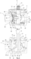
- a directional control valve according to the invention which is in particular a motor vehicle directional control valve for adjusting a fluid flow, such as a coolant flow in a motor vehicle, in particular a motor vehicle engine, is generally provided with the reference number 1.
- the valve housing 3 which is rotationally shaped and essentially has a cup shape, has a closed valve housing base 27.
- a central pivot bearing 29 for the valve member 5, in particular its actuating part 19, is provided in the valve housing base 27 in the valve housing base 27, a central pivot bearing 29 for the valve member 5, in particular its actuating part 19, is provided.
- the sealing part 21 is guided and supported within the guide groove 45 by means of a guide projection 51, 53 provided on an upper side 47 oriented in the direction of the rotary adjustment axis R and the opposite underside 49 of the sealing part 21. It is also conceivable for the sealing part 21 to have only a single guide projection 51, 53.
- the guide projection 51, 53 projects into the guide groove 45 in the direction of the rotary adjustment axis R and slides radially along the guide groove 45 during a rotary adjustment movement of the valve member 5.
- the guide projection 51, 53 acts as a sliding block and cooperates with the guide groove 45 to support and guide the valve member 5.
- the valve housing 3 comprises a seal receptacle 26 assigned to the fluid opening 7, in which an annular, one-piece seal 25 is arranged.
- the seal 25 usually has an L-shape in cross-section and is injected from the valve interior 81 into the seal receptacle 26 by means of an injection molding process.
- the seal receptacle 26 and the seal 25 are arranged concentrically with respect to the fluid opening 7 and circumferentially delimit it.
- the seal 25 is active and the sealing part 21 forms a sealing contact with the seal 25.
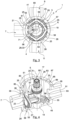
- Figure 3 is a top view of a valve housing 3 with mounted valve element 5, from which the slotted guide 39 and the rail guide 41 can be seen.
- the guide groove defining the slotted path 43 runs according to Figure 3 in the circumferential direction and concentric with respect to the rotary axis R and is delimited by two groove walls 55, 57 spaced apart in the radial direction.
- the radially inner Groove wall 55 is part of a circumferential web 56 or projection, which forms or delimits the guide groove 45.
- Each pressure lug 59 is also assigned to a fluid opening 7, 9, 10, 11 and is oriented concentrically with respect to a central axis through the respective fluid opening 7, 9, 10, 11, so that in order to assume the sealing contact switching state during a rotary adjustment movement of the valve member 5 about the rotary adjustment axis R, the sealing part 21 is urged radially outwards in the direction of the valve housing 3 by the pressure lugs 59 in order to build up a radial contact pressure for fluid-tight closing of the respective fluid openings 7, 9, 10, 11.
- the pressure lugs 59 thus cause the sealing part 21 to be deflected or redirected transversely, in particular radially, to the rotary adjustment axis.
- the relative movement option of the sealing part 21 relative to the adjustment part 19 is realized, as already described, by means of the rail guide 41.
- the rail guide 41 is realized on a projection-recess structure on the actuating part 19 and sealing part 21, which according to Figure 1 a linear guide rail 61 on the actuator side, which according to Figure 1 is formed by a pair of parallel extending guide rail elements, and comprises a sealing part-side guide carriage 71 of complementary shape.
- the guide carriage 71 is arranged by means of a recess that is shaped in relation to the guide rail 61 on an inner side of a guide part 65 that faces and is associated with the actuating part 19, which is shaped in relation to a guide part 67 on the actuating part side that faces and is associated with the sealing part 21, and is pushed or plugged onto it.
- the increased radial distance between the sealing part 21 and the rotary adjustment axis R is, for example, due to the radial distance of the sealing part-side guide rail 61 relative to the adjustment part 19 within the recess 69, which forms the guide carriage 71, in comparison to the design according to Figure 5 can be seen, in which the valve element is shown in the pivoting range between two sealing contact closing states.
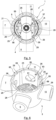
- the valve housing 3 from Figure 4 differs from the previous versions with regard to the design of the seal receptacle 26 and the seal 25.
- the directional control valve 1 comprises a total of 4 seals 25 (3 of which are shown), which are arranged in the circumferential direction with respect to the rotary axis R at a constant distance from each other.
- the seals 25 according to Figure 4 line the valve housing inner wall on the inside over a large area, so that the valve housing inner wall is essentially completely lined or covered by the seals, except for wall sections 83 extending in the direction of the rotary axis R. It is clear and is also so in Figure 4 shown that the seal receptacles 26 are shaped accordingly.
- the seals 25 each form a positive engagement with a seal receptacle 26, here in the form of a tongue and groove connection 85.
- the tongue and groove connections 85 are formed by several projection-recess pairs 87, 89 distributed in the circumferential direction. Because the seals 25 are each received and accommodated essentially completely within the seal receptacles 26, a continuous, projection-free transition is formed between the wall sections 83 and the seals 25, which ensures reliable positioning of the valve member 5.
- both the seal receptacles 26 and the seals 25 are adapted to the inner contours/or curvature of the wall sections 83 with regard to their inner contour and/or curvature.
- valve member 5 has two sealing parts 21 which are opposite in the radial direction with respect to the rotary adjustment axis R and are in particular identically shaped, and which are coupled to one another via a corresponding rail guide 39 in order to realize a possibility of relative movement of the two sealing parts 21 with respect to the single, central adjusting part 19.
- the valve member 5 according to Figure 5 is particularly suitable for a 4/2-way valve, whereby by means of the valve member 5 two opposite Fluid openings 7, 9, 10, 11 are closable.
- valve member 5 designed in this way closes two opposing fluid openings 7, 9, 10, 11 and opens the two other opposing fluid openings 7, 9, 11, 10.
- the permitted fluid flow through the valve housing 3 occurs in a straight line via two fluid openings 7, 9, 10, 11, which are particularly aligned with one another.
- the valve member 5 For guiding the fluid flow through the valve housing 3 and especially through the valve member 5 without any flow loss, the valve member 5 comprises, according to the Figure 5 a central fluid passage 79, which fluidically connects the two fluid openings 7, 9, 10, 11 to be released.
- An opening cross-section of the fluid passage 79 can be shaped to match an opening cross-section of the fluid openings 7, 9, 10, 11 of the fluid housing 3.
- the fluid passage 79 is oriented transversely, in particular vertically, on the one hand with respect to the rotary adjustment axis R and, on the other hand, with respect to the relative movement direction of the two actuating parts 21 with respect to the actuating part 19.
- Figure 5 It can be seen that when the valve member 5 is pivoted or positioned, a guide projection 53 of each of the two sealing parts 21 is received within the guide groove 45 defining the link path 43 in the valve housing 3 and slides along within the guide groove 45 when the valve member 5 is positioned. Due to the coordination of the link guide 39 and the rail guide 41, which is also present in this embodiment, the two sealing parts 21 are simultaneously pushed radially outwards into the sealing contact switching state with the respective fluid opening 7, 9, 10, 11 by a pressure lug 59, each of which is assigned to one of the two opposite fluid openings 7, 9, 10, 11 to be closed. Exiting the sealing contact switching state also takes place analogously and simultaneously for both sealing parts 21.
- valve body version 3 is made of Figure 4 once in a top view and once in a full perspective view, from which the large-area lining of the valve housing's inner wall is particularly evident.
- the Figures 7a to 10 illustrate further aspects of the present invention by describing an exemplary embodiment of a valve member 3 for a directional control valve 1.
- the sealing part 21 and the actuating part 19 are in an assembled state
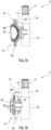
- the sealing part 21 has a sealing receptacle 26 on a front side 23 oriented radially outwards with respect to the rotary axis R, which serves as the sealing side, in order to achieve an improved fluid-tight closure of the fluid openings 7, 9, 10, 11 ( Figure 7a ).
- the seal receptacle 26 is annular, in particular annular groove-shaped, and is located close to the edge, i.e. radially outside on the end face 23.
- the seal receptacle 26 comprises, as shown in Figure 7b As can be seen, a plurality of form-locking openings 95 distributed in the circumferential direction, each for receiving a projection 97 whose shape is matched to the form-locking openings 95, so that the seal 25 and the seal receptacle 26 can engage with one another in a form-locking manner to prevent them from moving away from one another counter to the assembly direction.
- the form-locking openings 95 are designed as through-openings and extend from the end face 23 to the rear side 99. On the rear side 99, the form-locking openings 95 are shaped in the form of wooden cylindrical sleeves or nozzles.
- FIG 8 A sectional view of the valve member 5 with the seal 25 mounted is shown.
- the seal 25 and the seal receptacle 26 are shaped in such a way that the seal 25 and the seal receptacle 26 engage behind each other in a barb-like manner with respect to the mounting direction.
- This is shown in the exemplary embodiment in Figure 8 by a barb structure in the form of rotationally shaped projections 97 projecting from the seal, each having a web section 101, in particular of constant diameter, and a holding section 103 projecting, in particular circumferential, relative to the web section 101 transversely to the longitudinal extent of the projection 97.
- the form-fitting openings 95 of the seal receptacle 26 formed in the valve member 5 comprise a corresponding shape, namely a web receptacle 105 assigned to the web section 101 of the seal 25 and a holding receptacle 107 assigned to the holding section 103, projecting, in particular circumferentially, relative to the web receptacle 105 transversely to the longitudinal extent of the form-fitting opening 95.
- the seal 25 can, for example, be inserted, in particular pressed or clipped, into the seal receptacle in the assembly direction.
- the assembly direction is shown schematically in Figure 9 shown in which the seal 25 in With respect to the valve member 5 is dismantled.
- the seal 25 is secured against removal from the seal receptacle 26 or away from the valve member 5 by the positive engagement of the seal 25 and the seal receptacle 26, or the seal projection 97 and the positive engagement opening 95.
- the barb-like engagement of the holding sections 103 in the holding receptacles 107 relative to the radially recessed web receptacles 105 prevents unintentional disassembly of the seal 25 from the seal receptacle in 26.
- the holding sections 103 interlock with the receiving webs 105 and build up an axial holding force that prevents unintentional disassembly.
- FIG. 9 in which a disassembly state with respect to an exploded view of Figure 8
- an exemplary embodiment of an annular seal 25 with a plurality of circumferentially distributed sealing projections 97 is shown.
- Each sealing projection 97 is assigned a positive-locking opening 95 in the valve member 3, so that upon axial insertion or injection of the seal 25 into the seal receptacle 26, the sealing projections 97 increasingly protrude into the positive-locking openings 95 and protrude at the rear side 99 of the valve member 3 ( Figure 10
- the barbed structure of seal 25 and seal receptacle 26 enables a particularly robust, adhesion-promoting-free attachment of seal 25 to valve member 5.
- the seal 25 is manufactured in one piece, in particular by means of an injection molding process. It is possible for the seal 25 to be injected directly into the seal receptacle 26 via the manufacturing process, ie, the injection molding process.
- the sealing projections 97 can have leading guide webs 109, which can correspond in diameter to the web sections 105.
- the guide webs 109 enable particularly simple and/or targeted insertion of the seal 25 into the seal receptacle 26 and the corresponding form-fitting openings 95.
- the transition between the guide webs 109 and the holding sections 103 can be formed by a conical centering contour 111, which centers the sealing projections 97 in the form-fitting openings 95 when the seal 25 is inserted in the assembly direction M into the seal receptacle 26.
- Figure 10 shows the corresponding assembly state of the valve member 3 with the seal 25 compared to the disassembly state of Figure 9 . It can be seen that at least the guide webs 109 protrude from the form-fitting openings 95. From a comparison of Figure 10 with Figure 11 , which finally shows the installed state of the valve member 3 with the mounted seal 25 in the valve housing 5, it can be seen that the guide webs 109 have been separated.
- the guide webs 109 can thus be designed as a disposable product that has no function during operation of the directional control valve 1.
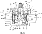
- valve member 5 corresponds to the embodiment of Figure 10 is formed in Figure 11 as single valve element 5 and in Figure 12 as double valve element 5 according to the design in Figure 5 .
Landscapes
- Engineering & Computer Science (AREA)
- General Engineering & Computer Science (AREA)
- Mechanical Engineering (AREA)
- Chemical & Material Sciences (AREA)
- Combustion & Propulsion (AREA)
- Multiple-Way Valves (AREA)
- Sliding Valves (AREA)
Claims (15)
- Soupape de distribution (1) pour le réglage d'un écoulement de fluide, comme un écoulement de fluide de refroidissement, comprenant :- un boîtier de soupape (3) avec au moins deux ouvertures de fluides, qui sont reliées avec un espace interne de soupape (81) délimité par le boîtier de soupape (3) et au moins un logement de joint d'étanchéité ;- un organe de soupape (5) qui peut être réglé pour la fermeture et l'ouverture au moins partielle des au moins deux ouvertures de fluides (7, 9, 10, 11) ; et- un joint d'étanchéité (25) injecté dans une direction de montage (M) au moyen d'un procédé d'injection, à partir de l'espace interne de soupape (81) vers l'au moins un logement de joint d'étanchéité (26) et constitué d'une seule pièce,caractérisée en ce que
le joint d'étanchéité (25) et le logement de joint d'étanchéité (26) s'emboîtent l'un dans l'autre par complémentarité de forme afin d'empêcher un éloignement du joint d'étanchéité (25) et du boîtier de soupape (3) à l'encontre de la direction de montage (M). - Soupape de distribution (1) selon la revendication 1, dans laquelle le logement de joint d'étanchéité (26) et le joint d'étanchéité (25) présentent des formes complémentaires de sorte que le joint d'étanchéité (25) et le logement de joint d'étanchéité (26) s'accrochent par l'arrière, par rapport à la direction de montage (M), à la manière de contre-crochets.
- Soupape de distribution (1) selon la revendication 1 ou 2, dans laquelle le joint d'étanchéité (25) comprend une structure de contre-crochet réalisée d'une seule pièce, à l'aide de laquelle le joint d'étanchéité (25) est monté fermement, plus particulièrement sans promoteur d'adhérence, sur l'organe de soupape (5) ou le boîtier de soupape (3).
- Soupape de distribution (1) selon la revendication 3, dans laquelle la structure de contre-crochet est réalisée comme une saillie dépassant, plus particulièrement sous une forme rotative, du joint d'étanchéité (25), qui comprend une portion d'entretoise d'un diamètre plus particulièrement constant et une portion de maintien dépassant par rapport à la portion d'entretoise transversalement par rapport à l'extension longitudinale de la saillie, plus particulièrement circulaire.
- Soupape de distribution (1) selon la revendication 4, dans laquelle le joint d'étanchéité (25) comprend au moins deux, plus particulièrement une pluralité de saillies disposées à des intervalles réguliers entre elles, plus particulièrement de même forme, dans lequel, plus particulièrement, le joint d'étanchéité (25) est conçu comme une bague d'étanchéité.
- Soupape de distribution (1) selon l'une des revendications précédentes, dans laquelle le logement de joint d'étanchéité (26) présente une forme annulaire, plus particulièrement une forme de rainure annulaire et/ou comprend au moins une ouverture à complémentarité de forme (95), pour la réception de la saillie, dont la forme est adaptée à l'au moins une saillie du joint d'étanchéité (25).
- Soupape de distribution (1) selon la revendication 6, dans laquelle l'ouverture à complémentarité de forme (95) présente une forme telle que la saillie du joint d'étanchéité et l'ouverture à complémentarité de forme du logement de joint d'étanchéité (25) s'accrochent par l'arrière, par rapport à la direction de montage (M), à la manière de contre-crochets.
- Soupape de distribution (1) selon la revendication 6 ou 7, dans laquelle l'ouverture à complémentarité de forme (95) comprend un logement d'entretoise correspondant à la portion d'entretoise du joint d'étanchéité (25) et un logement de maintien correspondant à la portion de maintien, dépassant du logement d'entretoise transversalement par rapport à l'extension longitudinale de l'ouverture à complémentarité de forme (95), plus particulièrement circulaire.
- Soupape de distribution (1) selon l'une des revendications précédentes, dans laquelle le logement de joint d'étanchéité (26) est réalisé près du bord, dans une partie étanche de l'organe de soupape (5), conçu pour l'établissement d'un contact étanche avec le boîtier de soupape (3) ou près de l'ouverture de fluide dans une paroi du boîtier de soupape délimitant les au moins deux ouvertures de fluides (7, 9, 10, 11).
- Soupape de distribution (1) selon l'une des revendications précédentes, dans laquelle le joint d'étanchéité (25) présente une forme telle que le joint d'étanchéité (25) est adapté à un contour interne de la paroi du boîtier de soupape, plus particulièrement se raccorde de manière continue et/ou sans saillie au contour de la paroi.
- Soupape de distribution (1) selon l'une des revendications précédentes, dans laquelle le joint d'étanchéité (25) est disposé dans l'au moins un logement de joint d'étanchéité (26) de sorte qu'une rotation du joint d'étanchéité (25) par rapport au logement de joint d'étanchéité (26) autour de l'axe de réglage de l'organe de soupape (5) et/ou une translation du joint d'étanchéité (25) par rapport au logement de joint d'étanchéité (26) en direction de l'axe de réglage est empêchée.
- Soupape de distribution (1) selon la revendication 11, dans laquelle le joint d'étanchéité (25) et le logement de joint d'étanchéité (26) forment un emboîtement par complémentarité de forme plus particulièrement sous la forme d'une liaison par rainure et languette (85).
- Soupape de distribution (1) selon l'une des revendications précédentes, dans laquelle le joint d'étanchéité (25) recouvre une grande surface de la paroi du boîtier de soupape, plus particulièrement au moins 50 %, au moins 60 %, au moins 70 % ou au moins 80 % de la paroi du boîtier de soupape.
- Soupape de distribution (1) selon l'une des revendications précédentes, dans laquelle l'organe de soupape (5) est comprimé entre un état de fermeture, dans lequel l'organe de soupape (5) est comprimé en contact étanche avec le boîtier de soupape (3) et dans lequel le joint d'étanchéité (25) est actif, afin de fermer une des ouvertures de fluides (7, 9, 10, 11) de manière étanche aux fluides, et un état d'ouverture dans lequel l'organe de soupape (5) est déplacé à nouveau loin du boîtier de soupape (3) et dans lequel le joint d'étanchéité (25) est inactif, afin d'ouvrir au moins partiellement l'ouverture de fluide (7, 9, 10, 11).
- Système de guidage d'écoulement de fluides de poids-lourd, plus particulièrement système de guidage de fluides de gestion thermique de poids-lourd, comme un circuit de refroidissement de poids-lourd, comprenant une soupape de distribution (1) conçue selon l'une des revendications précédentes.
Applications Claiming Priority (1)
| Application Number | Priority Date | Filing Date | Title |
|---|---|---|---|
| DE102021100075.0A DE102021100075A1 (de) | 2021-01-05 | 2021-01-05 | KFZ-Wegeventil zum Einstellen einer Fluidströmung |
Publications (3)
| Publication Number | Publication Date |
|---|---|
| EP4086490A1 EP4086490A1 (fr) | 2022-11-09 |
| EP4086490C0 EP4086490C0 (fr) | 2025-06-25 |
| EP4086490B1 true EP4086490B1 (fr) | 2025-06-25 |
Family
ID=79024345
Family Applications (1)
| Application Number | Title | Priority Date | Filing Date |
|---|---|---|---|
| EP21214826.6A Active EP4086490B1 (fr) | 2021-01-05 | 2021-12-15 | Soupape directionnelle de véhicule à moteur permettant de régler un écoulement de fluide |
Country Status (4)
| Country | Link |
|---|---|
| US (1) | US12018773B2 (fr) |
| EP (1) | EP4086490B1 (fr) |
| CN (1) | CN114719057A (fr) |
| DE (1) | DE102021100075A1 (fr) |
Families Citing this family (7)
| Publication number | Priority date | Publication date | Assignee | Title |
|---|---|---|---|---|
| EP4356029B1 (fr) * | 2021-06-14 | 2025-07-30 | HELLA GmbH & Co. KGaA | Vanne à voies multiples pour un véhicule électrique, système de gestion thermique et procédé de fonctionnement d'un système de gestion thermique |
| DE102022115697A1 (de) * | 2022-06-23 | 2023-12-28 | Woco Industrietechnik Gmbh | Ventilgehäuse mit Dichtungsaufnahmetaschen eines KFZ-Wegeventils zum Einstellen einer Fluidströmung |
| FR3138488B1 (fr) * | 2022-07-27 | 2025-02-21 | Bontaz Centre R&D | Distributeur a joint incorpore, et procede de realisation |
| WO2024188426A1 (fr) * | 2023-03-10 | 2024-09-19 | ECO Holding 1 GmbH | Soupape de commande de fluide, système de refroidissement d'un véhicule automobile et véhicule automobile présentant une telle soupape de commande de fluide |
| CN116608294A (zh) * | 2023-05-25 | 2023-08-18 | 深圳市名雕装饰股份有限公司 | 一种可循环的u型三通 |
| EP4381210B1 (fr) * | 2023-07-05 | 2025-08-06 | Franklin Valve, LP | Soupape à bouchon à sièges multiples |
| DE102024101846A1 (de) * | 2024-01-23 | 2025-07-24 | Voss Automotive Gmbh | Mehrwegeventil |
Citations (1)
| Publication number | Priority date | Publication date | Assignee | Title |
|---|---|---|---|---|
| DE102014004296A1 (de) * | 2014-03-25 | 2015-10-01 | Festo Ag & Co. Kg | Ventilbausatz, daraus hergestelltes Ventil und Verfahren zur Herstellung eines Ventils |
Family Cites Families (20)
| Publication number | Priority date | Publication date | Assignee | Title |
|---|---|---|---|---|
| DE176433C (fr) | ||||
| DE551241C (de) | 1928-04-17 | 1932-05-30 | Ewald Haselhorst | Drehschieber |
| DE690270C (de) | 1938-03-23 | 1940-04-20 | Richard Kraus | Absperrhahn mit Kugelgehaeuse und kugeligem Hahnkueken |
| US2310583A (en) * | 1941-04-03 | 1943-02-09 | Reed Roller Bit Co | Valve |
| FR1314566A (fr) * | 1961-12-01 | 1963-01-11 | Dispositif à une ou plusieurs vannes rotatives et appareils comportant ce dispositif | |
| FR1407362A (fr) | 1964-08-05 | 1965-07-30 | Koltek Oy | Robinet d'arrêt |
| US6315267B1 (en) * | 1999-09-16 | 2001-11-13 | Eaton Corporation | Electrically controlled servo operated engine coolant valve |
| FR2844571B1 (fr) * | 2002-09-18 | 2008-02-29 | Valeo Thermique Moteur Sa | Vanne de commande pour un circuit de fluide et circuit comportant cette vanne |
| DE102008016602A1 (de) * | 2008-04-01 | 2009-10-08 | Festo Ag & Co. Kg | Drehschieberventil |
| DE102009049867A1 (de) | 2009-10-20 | 2011-04-21 | Mahle International Gmbh | Ventileinrichtung |
| DE102013105321A1 (de) | 2013-05-23 | 2014-11-27 | Woco Industrietechnik Gmbh | Mehrwegeventil sowie Verfahren zum Betreiben und Verwendung eines solchen Mehrwegeventils |
| DE202014008139U1 (de) * | 2014-10-14 | 2015-01-22 | Henzel Formenbau Gmbh | Mehrwegeventil zur Steuerung von Flüssigkeitskreisen |
| DE102016118133A1 (de) | 2016-09-26 | 2018-03-29 | Pierburg Gmbh | Drehschieberventil |
| CN107917219A (zh) * | 2016-10-11 | 2018-04-17 | 浙江三花旋转阀有限公司 | 旋转式流路切换阀 |
| DE202017000564U1 (de) | 2017-02-02 | 2017-03-20 | Henzel Automotive GmbH | Dichtungspaket für ein Mehrwegeventil |
| WO2019206510A1 (fr) | 2018-04-23 | 2019-10-31 | Belimo Holding Ag | Vanne à 6 voies et procédé de fabrication d'une vanne à 6 voies |
| CN108708992A (zh) * | 2018-08-07 | 2018-10-26 | 台州力和环保科技有限公司 | 一种阀芯 |
| US10914390B2 (en) * | 2019-06-06 | 2021-02-09 | Robert Bosch Llc | Fluid valve assembly including valve body with seal retention features |
| CN110185812B (zh) | 2019-06-17 | 2020-06-30 | 特技阀门集团有限公司 | 一种球阀 |
| CN110173574B (zh) | 2019-06-21 | 2020-08-11 | 浙江英佰特阀门制造有限公司 | 一种长使用寿命球阀 |
-
2021
- 2021-01-05 DE DE102021100075.0A patent/DE102021100075A1/de active Pending
- 2021-12-15 EP EP21214826.6A patent/EP4086490B1/fr active Active
- 2021-12-30 US US17/566,222 patent/US12018773B2/en active Active
-
2022
- 2022-01-05 CN CN202210004631.5A patent/CN114719057A/zh active Pending
Patent Citations (1)
| Publication number | Priority date | Publication date | Assignee | Title |
|---|---|---|---|---|
| DE102014004296A1 (de) * | 2014-03-25 | 2015-10-01 | Festo Ag & Co. Kg | Ventilbausatz, daraus hergestelltes Ventil und Verfahren zur Herstellung eines Ventils |
Also Published As
| Publication number | Publication date |
|---|---|
| CN114719057A (zh) | 2022-07-08 |
| EP4086490C0 (fr) | 2025-06-25 |
| US12018773B2 (en) | 2024-06-25 |
| EP4086490A1 (fr) | 2022-11-09 |
| DE102021100075A1 (de) | 2022-07-07 |
| US20220213962A1 (en) | 2022-07-07 |
Similar Documents
| Publication | Publication Date | Title |
|---|---|---|
| EP4086490B1 (fr) | Soupape directionnelle de véhicule à moteur permettant de régler un écoulement de fluide | |
| DE10205177A1 (de) | Hydraulisches System | |
| DE4129828C1 (fr) | ||
| WO2012100844A1 (fr) | Suspension à bras de levier pour une tête d'application | |
| WO2023247777A1 (fr) | Boîtier de soupape à poches de réception de joint d'un distributeur de véhicule à moteur, destiné à régler un écoulement de fluide | |
| EP2426050A2 (fr) | Elément de coussinet d'un palier de gouvernail | |
| EP3175153A1 (fr) | Dispositif d'actionnement hydraulique pour actionner des actionneurs dans une boîte de vitesses de véhicule automobile | |
| DE102009014817A1 (de) | Fluidbetätigter Linearantrieb | |
| EP0257354A1 (fr) | Poussoir de soupape à autoréglage hydraulique | |
| EP0726413A1 (fr) | Soupape actionnée par le fluide contrÔlé | |
| EP0983455B1 (fr) | Soupape a double siege de commutation sans fuites | |
| EP4027042A1 (fr) | Soupape directionnelle de véhicule à moteur permettant de régler un écoulement de fluide | |
| EP1058037B1 (fr) | Piston pour un cylindre et son procédé de fabrication | |
| DE102021202181A1 (de) | Ventileinrichtung | |
| DE102005003982A1 (de) | Pneumatisches Wegeventil mit einem Ventilschieber | |
| DE19944083A1 (de) | Zentralausrücker für eine hydraulische Kupplungsbetätigung | |
| DE10041881B4 (de) | Kunststoffträger mit Dichtring | |
| EP2994674B1 (fr) | Vanne | |
| DE102023101360A1 (de) | Ventil mit Arretierung | |
| EP4291801A1 (fr) | Ensemble pour une unité piston-cylindre remplie de fluide et unité piston-cylindre remplie de fluide dotée d'un ensemble de ce type | |
| EP2994675B1 (fr) | Vanne | |
| EP3855054A1 (fr) | Soupape à voies multiples pour un fluide pour un dispositif de préparation de boisson, soupape à fluides multiples à voies multiples pour un dispositif de préparation de boisson et dispositif de préparation de boisson, en particulier machine à café | |
| EP1410892B1 (fr) | Moule à canaux chauds avec un appareil pour ouvrir et fermer des buses d'injection | |
| DE102015203715B3 (de) | Ventiltrieb einer Brennkraftmaschine | |
| DE10334206B4 (de) | Ventileinheit |
Legal Events
| Date | Code | Title | Description |
|---|---|---|---|
| PUAI | Public reference made under article 153(3) epc to a published international application that has entered the european phase |
Free format text: ORIGINAL CODE: 0009012 |
|
| STAA | Information on the status of an ep patent application or granted ep patent |
Free format text: STATUS: THE APPLICATION HAS BEEN PUBLISHED |
|
| AK | Designated contracting states |
Kind code of ref document: A1 Designated state(s): AL AT BE BG CH CY CZ DE DK EE ES FI FR GB GR HR HU IE IS IT LI LT LU LV MC MK MT NL NO PL PT RO RS SE SI SK SM TR |
|
| STAA | Information on the status of an ep patent application or granted ep patent |
Free format text: STATUS: REQUEST FOR EXAMINATION WAS MADE |
|
| 17P | Request for examination filed |
Effective date: 20230509 |
|
| RBV | Designated contracting states (corrected) |
Designated state(s): AL AT BE BG CH CY CZ DE DK EE ES FI FR GB GR HR HU IE IS IT LI LT LU LV MC MK MT NL NO PL PT RO RS SE SI SK SM TR |
|
| P01 | Opt-out of the competence of the unified patent court (upc) registered |
Effective date: 20230526 |
|
| REG | Reference to a national code |
Ref country code: DE Ref legal event code: R079 Free format text: PREVIOUS MAIN CLASS: F16K0011085000 Ipc: F01P0007160000 Ref country code: DE Ref legal event code: R079 Ref document number: 502021007834 Country of ref document: DE Free format text: PREVIOUS MAIN CLASS: F16K0011085000 Ipc: F01P0007160000 |
|
| GRAP | Despatch of communication of intention to grant a patent |
Free format text: ORIGINAL CODE: EPIDOSNIGR1 |
|
| STAA | Information on the status of an ep patent application or granted ep patent |
Free format text: STATUS: GRANT OF PATENT IS INTENDED |
|
| INTG | Intention to grant announced |
Effective date: 20241216 |
|
| RIC1 | Information provided on ipc code assigned before grant |
Ipc: F01P 7/16 20060101AFI20241206BHEP |
|
| GRAS | Grant fee paid |
Free format text: ORIGINAL CODE: EPIDOSNIGR3 |
|
| GRAA | (expected) grant |
Free format text: ORIGINAL CODE: 0009210 |
|
| STAA | Information on the status of an ep patent application or granted ep patent |
Free format text: STATUS: THE PATENT HAS BEEN GRANTED |
|
| AK | Designated contracting states |
Kind code of ref document: B1 Designated state(s): AL AT BE BG CH CY CZ DE DK EE ES FI FR GB GR HR HU IE IS IT LI LT LU LV MC MK MT NL NO PL PT RO RS SE SI SK SM TR |
|
| REG | Reference to a national code |
Ref country code: GB Ref legal event code: FG4D Free format text: NOT ENGLISH |
|
| REG | Reference to a national code |
Ref country code: CH Ref legal event code: EP |
|
| REG | Reference to a national code |
Ref country code: CH Ref legal event code: EP |
|
| REG | Reference to a national code |
Ref country code: IE Ref legal event code: FG4D Free format text: LANGUAGE OF EP DOCUMENT: GERMAN |
|
| U01 | Request for unitary effect filed |
Effective date: 20250625 |
|
| U07 | Unitary effect registered |
Designated state(s): AT BE BG DE DK EE FI FR IT LT LU LV MT NL PT RO SE SI Effective date: 20250701 |
|
| P04 | Withdrawal of opt-out of the competence of the unified patent court (upc) registered |
Free format text: CASE NUMBER: APP_30996/2025 Effective date: 20250627 |
|
| PG25 | Lapsed in a contracting state [announced via postgrant information from national office to epo] |
Ref country code: GR Free format text: LAPSE BECAUSE OF FAILURE TO SUBMIT A TRANSLATION OF THE DESCRIPTION OR TO PAY THE FEE WITHIN THE PRESCRIBED TIME-LIMIT Effective date: 20250926 Ref country code: NO Free format text: LAPSE BECAUSE OF FAILURE TO SUBMIT A TRANSLATION OF THE DESCRIPTION OR TO PAY THE FEE WITHIN THE PRESCRIBED TIME-LIMIT Effective date: 20250925 |
|
| PG25 | Lapsed in a contracting state [announced via postgrant information from national office to epo] |
Ref country code: HR Free format text: LAPSE BECAUSE OF FAILURE TO SUBMIT A TRANSLATION OF THE DESCRIPTION OR TO PAY THE FEE WITHIN THE PRESCRIBED TIME-LIMIT Effective date: 20250625 |
|
| PG25 | Lapsed in a contracting state [announced via postgrant information from national office to epo] |
Ref country code: RS Free format text: LAPSE BECAUSE OF FAILURE TO SUBMIT A TRANSLATION OF THE DESCRIPTION OR TO PAY THE FEE WITHIN THE PRESCRIBED TIME-LIMIT Effective date: 20250925 |
|
| PG25 | Lapsed in a contracting state [announced via postgrant information from national office to epo] |
Ref country code: IS Free format text: LAPSE BECAUSE OF FAILURE TO SUBMIT A TRANSLATION OF THE DESCRIPTION OR TO PAY THE FEE WITHIN THE PRESCRIBED TIME-LIMIT Effective date: 20251025 |
|
| PG25 | Lapsed in a contracting state [announced via postgrant information from national office to epo] |
Ref country code: SM Free format text: LAPSE BECAUSE OF FAILURE TO SUBMIT A TRANSLATION OF THE DESCRIPTION OR TO PAY THE FEE WITHIN THE PRESCRIBED TIME-LIMIT Effective date: 20250625 |
|
| PG25 | Lapsed in a contracting state [announced via postgrant information from national office to epo] |
Ref country code: CZ Free format text: LAPSE BECAUSE OF FAILURE TO SUBMIT A TRANSLATION OF THE DESCRIPTION OR TO PAY THE FEE WITHIN THE PRESCRIBED TIME-LIMIT Effective date: 20250625 |
|
| PG25 | Lapsed in a contracting state [announced via postgrant information from national office to epo] |
Ref country code: PL Free format text: LAPSE BECAUSE OF FAILURE TO SUBMIT A TRANSLATION OF THE DESCRIPTION OR TO PAY THE FEE WITHIN THE PRESCRIBED TIME-LIMIT Effective date: 20250625 |
|
| PG25 | Lapsed in a contracting state [announced via postgrant information from national office to epo] |
Ref country code: SK Free format text: LAPSE BECAUSE OF FAILURE TO SUBMIT A TRANSLATION OF THE DESCRIPTION OR TO PAY THE FEE WITHIN THE PRESCRIBED TIME-LIMIT Effective date: 20250625 |
|
| PG25 | Lapsed in a contracting state [announced via postgrant information from national office to epo] |
Ref country code: ES Free format text: LAPSE BECAUSE OF FAILURE TO SUBMIT A TRANSLATION OF THE DESCRIPTION OR TO PAY THE FEE WITHIN THE PRESCRIBED TIME-LIMIT Effective date: 20250625 |
|
| PLBE | No opposition filed within time limit |
Free format text: ORIGINAL CODE: 0009261 |
|
| STAA | Information on the status of an ep patent application or granted ep patent |
Free format text: STATUS: NO OPPOSITION FILED WITHIN TIME LIMIT |