EP4086524B1 - Installation de production d'eau chaude potable - Google Patents
Installation de production d'eau chaude potable Download PDFInfo
- Publication number
- EP4086524B1 EP4086524B1 EP22171751.5A EP22171751A EP4086524B1 EP 4086524 B1 EP4086524 B1 EP 4086524B1 EP 22171751 A EP22171751 A EP 22171751A EP 4086524 B1 EP4086524 B1 EP 4086524B1
- Authority
- EP
- European Patent Office
- Prior art keywords
- heating
- unit
- drinking water
- room
- hot drinking
- Prior art date
- Legal status (The legal status is an assumption and is not a legal conclusion. Google has not performed a legal analysis and makes no representation as to the accuracy of the status listed.)
- Active
Links
Images

Classifications
-
- F—MECHANICAL ENGINEERING; LIGHTING; HEATING; WEAPONS; BLASTING
- F24—HEATING; RANGES; VENTILATING
- F24D—DOMESTIC- OR SPACE-HEATING SYSTEMS, e.g. CENTRAL HEATING SYSTEMS; DOMESTIC HOT-WATER SUPPLY SYSTEMS; ELEMENTS OR COMPONENTS THEREFOR
- F24D3/00—Hot-water central heating systems
- F24D3/08—Hot-water central heating systems in combination with systems for domestic hot-water supply
- F24D3/082—Hot water storage tanks specially adapted therefor
-
- F—MECHANICAL ENGINEERING; LIGHTING; HEATING; WEAPONS; BLASTING
- F24—HEATING; RANGES; VENTILATING
- F24D—DOMESTIC- OR SPACE-HEATING SYSTEMS, e.g. CENTRAL HEATING SYSTEMS; DOMESTIC HOT-WATER SUPPLY SYSTEMS; ELEMENTS OR COMPONENTS THEREFOR
- F24D17/00—Domestic hot-water supply systems
- F24D17/02—Domestic hot-water supply systems using heat pumps
-
- F—MECHANICAL ENGINEERING; LIGHTING; HEATING; WEAPONS; BLASTING
- F24—HEATING; RANGES; VENTILATING
- F24D—DOMESTIC- OR SPACE-HEATING SYSTEMS, e.g. CENTRAL HEATING SYSTEMS; DOMESTIC HOT-WATER SUPPLY SYSTEMS; ELEMENTS OR COMPONENTS THEREFOR
- F24D3/00—Hot-water central heating systems
- F24D3/18—Hot-water central heating systems using heat pumps
-
- F—MECHANICAL ENGINEERING; LIGHTING; HEATING; WEAPONS; BLASTING
- F24—HEATING; RANGES; VENTILATING
- F24F—AIR-CONDITIONING; AIR-HUMIDIFICATION; VENTILATION; USE OF AIR CURRENTS FOR SCREENING
- F24F5/00—Air-conditioning systems or apparatus not covered by F24F1/00 or F24F3/00, e.g. using solar heat or combined with household units such as an oven or water heater
- F24F5/0096—Air-conditioning systems or apparatus not covered by F24F1/00 or F24F3/00, e.g. using solar heat or combined with household units such as an oven or water heater combined with domestic apparatus
-
- F—MECHANICAL ENGINEERING; LIGHTING; HEATING; WEAPONS; BLASTING
- F24—HEATING; RANGES; VENTILATING
- F24H—FLUID HEATERS, e.g. WATER OR AIR HEATERS, HAVING HEAT-GENERATING MEANS, e.g. HEAT PUMPS, IN GENERAL
- F24H1/00—Water heaters, e.g. boilers, continuous-flow heaters or water-storage heaters
- F24H1/18—Water-storage heaters
- F24H1/20—Water-storage heaters with immersed heating elements, e.g. electric elements or furnace tubes
- F24H1/201—Water-storage heaters with immersed heating elements, e.g. electric elements or furnace tubes using electric energy supply
- F24H1/202—Water-storage heaters with immersed heating elements, e.g. electric elements or furnace tubes using electric energy supply with resistances
-
- F—MECHANICAL ENGINEERING; LIGHTING; HEATING; WEAPONS; BLASTING
- F24—HEATING; RANGES; VENTILATING
- F24H—FLUID HEATERS, e.g. WATER OR AIR HEATERS, HAVING HEAT-GENERATING MEANS, e.g. HEAT PUMPS, IN GENERAL
- F24H1/00—Water heaters, e.g. boilers, continuous-flow heaters or water-storage heaters
- F24H1/18—Water-storage heaters
- F24H1/20—Water-storage heaters with immersed heating elements, e.g. electric elements or furnace tubes
- F24H1/208—Water-storage heaters with immersed heating elements, e.g. electric elements or furnace tubes with tubes filled with heat transfer fluid
-
- F—MECHANICAL ENGINEERING; LIGHTING; HEATING; WEAPONS; BLASTING
- F24—HEATING; RANGES; VENTILATING
- F24H—FLUID HEATERS, e.g. WATER OR AIR HEATERS, HAVING HEAT-GENERATING MEANS, e.g. HEAT PUMPS, IN GENERAL
- F24H4/00—Fluid heaters characterised by the use of heat pumps
- F24H4/02—Water heaters
- F24H4/04—Storage heaters
-
- F—MECHANICAL ENGINEERING; LIGHTING; HEATING; WEAPONS; BLASTING
- F24—HEATING; RANGES; VENTILATING
- F24H—FLUID HEATERS, e.g. WATER OR AIR HEATERS, HAVING HEAT-GENERATING MEANS, e.g. HEAT PUMPS, IN GENERAL
- F24H6/00—Combined water and air heaters
-
- F—MECHANICAL ENGINEERING; LIGHTING; HEATING; WEAPONS; BLASTING
- F24—HEATING; RANGES; VENTILATING
- F24H—FLUID HEATERS, e.g. WATER OR AIR HEATERS, HAVING HEAT-GENERATING MEANS, e.g. HEAT PUMPS, IN GENERAL
- F24H9/00—Details
- F24H9/02—Casings; Cover lids; Ornamental panels
-
- F—MECHANICAL ENGINEERING; LIGHTING; HEATING; WEAPONS; BLASTING
- F24—HEATING; RANGES; VENTILATING
- F24D—DOMESTIC- OR SPACE-HEATING SYSTEMS, e.g. CENTRAL HEATING SYSTEMS; DOMESTIC HOT-WATER SUPPLY SYSTEMS; ELEMENTS OR COMPONENTS THEREFOR
- F24D2200/00—Heat sources or energy sources
- F24D2200/08—Electric heater
-
- F—MECHANICAL ENGINEERING; LIGHTING; HEATING; WEAPONS; BLASTING
- F24—HEATING; RANGES; VENTILATING
- F24D—DOMESTIC- OR SPACE-HEATING SYSTEMS, e.g. CENTRAL HEATING SYSTEMS; DOMESTIC HOT-WATER SUPPLY SYSTEMS; ELEMENTS OR COMPONENTS THEREFOR
- F24D2200/00—Heat sources or energy sources
- F24D2200/12—Heat pump
-
- F—MECHANICAL ENGINEERING; LIGHTING; HEATING; WEAPONS; BLASTING
- F24—HEATING; RANGES; VENTILATING
- F24D—DOMESTIC- OR SPACE-HEATING SYSTEMS, e.g. CENTRAL HEATING SYSTEMS; DOMESTIC HOT-WATER SUPPLY SYSTEMS; ELEMENTS OR COMPONENTS THEREFOR
- F24D2220/00—Components of central heating installations excluding heat sources
- F24D2220/08—Storage tanks
Definitions
- the invention relates to a domestic hot water generation system.
- heating and air conditioning systems In residential construction, especially in multi-story low-energy residential buildings, very high costs are currently and even more so in the future due to work to prepare heating and air conditioning systems. This includes the complex installation of piping systems for air, heating, and hot water. Heating and domestic hot water are prepared separately by a central heating system and then pumped separately to the consumers.
- the costs for structural engineering, such as plumbing and heat supply amount to approximately 7.5% of the construction costs for new buildings, and can sometimes reach up to 12.5% when using controlled living space ventilation.
- the costs of building extensions will continue to rise in the future due to the use of new, more environmentally friendly technologies, as the installation of piping is resource-intensive.
- the owner or builder of a new building is required to purchase various services and products from different suppliers. These include, for example, a heat generator, water heater, heat distribution system (e.g., radiators or underfloor heating), optional cooling, individual room control, water heater, heating circuit manifold, heat meter, and the installation of these components.
- a heat generator e.g., water heater, heat distribution system (e.g., radiators or underfloor heating), optional cooling, individual room control, water heater, heating circuit manifold, heat meter, and the installation of these components.
- TTA hot water heat pump For example, a so-called “TTA hot water heat pump” from tecalor is already available. This includes a hot water boiler or hot water storage tank whose drinking water can be heated using a small heat pump. For this purpose, ambient air is drawn in, and its thermal energy is used by a heat exchanger to heat the stored drinking water or hot water.
- This hot water generator is usually located in the basement and often draws in outside air or basement air, which is then used as a heat source or cooled down and released into the atmosphere via air ducts/pipes.
- the hot water generated centrally or in the basement is then piped to the individual floors or rooms via a house plumbing system and used at the individual water taps of the existing sinks, showers, bathtubs, or kitchen faucets.
- Such a domestic hot water generator is made of DE19702903 A1 known.
- the object of the invention is to propose a domestic hot water production system which at least partially improves the disadvantages of the prior art.
- a domestic hot water generation system is characterized in that at least one building space heating surface for heating/warming the building space is provided at least on the housing and/or the casing.
- the building space can be heated directly by the casing and/or the cladding, i.e., the one present on the contour/cladding/shell/housing or that encloses the domestic hot water generation unit.
- the building space preferably a living space, in which the domestic hot water generation unit or a so-called "room unit” is installed or arranged, can be heated directly by the domestic hot water generation unit or without (long or complex) heating pipes and/or without underfloor heating or underfloor heating loops, or without radiators or the like. Accordingly, complex radiators, radiators, or underfloor heating can be omitted in this room and possibly also in neighboring rooms of the apartment/residential unit.
- the invention also advantageously reduces the time required for installation, i.e., the construction time.
- the domestic hot water generation unit according to the invention is designed as a room heating element of the building/living space.
- a domestic hot water generation unit according to the invention is located in each building space that is to be heated or where heating is required, e.g., in the living room and/or bathroom and/or kitchen and/or study, or the like. It is preferred to provide only a single domestic hot water generation unit per residential unit or apartment. This is cost-effective, space-saving, and sufficient in terms of the required heating energy.
- At least one heating water heat exchanger unit comprises the building space heating surface, wherein the heating water heat exchanger unit is arranged within the housing and/or the casing. This advantageously allows heat exchange between the domestic hot water generation unit and the building space/living space to be realized.
- At least one heating unit is provided for heating the building's heating surface.
- this unit is designed as a heat pump, in particular a brine heat pump, an air heat pump, a condensing boiler, a district heating system, a gas burner, or the like.
- the heating unit is arranged/housed as a separate device or in a separate device housing.
- an air-source heat pump can be installed on a building's roof, or a brine heat pump with a geothermal heat exchanger can be installed in the basement or garden of the building. District heating or an external heat source can also be used to generate energy. Accordingly, a particularly efficient energy supply can be achieved.
- the heating unit is designed as an external energy source for generating thermal energy, so that at least the domestic hot water storage tank and the domestic hot water heat exchanger device can be heated with the thermal energy of the external energy source/heating unit.
- This advantageously implements a dual use of the domestic hot water generation unit according to the invention, namely a single device or unit that is used to heat the domestic hot water or the domestic hot water storage tank and, at the same time, Heating of the building space or as apartment/building heating, using an external energy/heat source.
- the flexibility with regard to the energy/heating sources used or usable such as district heating/network, wood or gas/oil heating, or heat pump heating such as air-water and/or brine and/or geothermal heat pump heating, etc.
- the domestic hot water generation unit according to the invention can be adapted to a wide variety of needs and/or conditions. This allows for use in both new buildings and existing buildings, as well as renovations or retrofits.
- a heating fluid unit and/or at least two heating fluid lines are provided/arranged between the housing/casing and the heating unit and/or the separate device and/or the separate device housing.
- a central heating unit can be provided for several domestic hot water generation units and/or apartments/residential units in a building, which can be connected to the aforementioned heating fluid unit and/or at least two heating fluid lines.
- a separate/specific domestic hot water generation unit can be used/provided for each apartment/residential unit.
- a building preferably comprises several residential units/apartments with at least one building room and/or living space, wherein each of the several residential units/apartments comprises a domestic hot water generation unit and a residential heating unit designed as the heating unit (19) and/or separate device and/or external energy source (19) and/or Residential heat pump unit and/or residential cooling unit. This further improves adaptability to a wide range of conditions.
- the housing and/or casing comprises at least one air inlet opening for the inflow of room air from the building space and at least one air outlet opening for the outflow of room air into the building space. This allows for the generation of a beneficial (active or passive) air flow and/or convection flow through the domestic hot water generation unit or along/on the building space heating surface, thereby heating the building space.
- the heating water heat exchanger unit has at least one blower and/or a fan for generating an airflow and/or for drawing in room air from the building, particularly through the air inlet opening, and/or for expelling room air into the building, particularly through the air outlet opening. This further advantageously improves the energy transfer between the domestic hot water generation unit and the building/living space.
- this measure can also be advantageously used, for example, to electrically heat the heating fluid in the event of a failure of the usual heating source. This is done by extracting the energy introduced by the electric heating element via the water-water heat exchanger integrated in the drinking water tank and using it for space heating. This is particularly advantageous as an emergency operation in the event of a failure of the conventional energy source, e.g., failure of the district heating or heat pump.
- At least one cooling unit is provided for cooling a cooling surface.
- a heat pump in particular a brine heat pump or preferably an air heat pump, is provided, which can be configured/used either as a heating unit or as a cooling unit.
- the building space heating surface is designed as a cooling surface of the cooling unit.
- thermal energy can be supplied to the building space via the building space heating surface, ie for heating/warming the building space, and on the other hand, thermal energy can be supplied to the building space via be taken/removed from the building space heating/cooling surface.
- control elements such as valves or the like and/or advantageous sensors, in particular temperature, pressure, flow, or quantity sensors, etc., can advantageously be provided.
- advantageous monitoring or control of the system or system unit according to the invention in particular an electrical and/or electronic and/or semi-automated/automated mode of operation. This allows for optimized, energy-saving, and climate-friendly energy use.
- blower and/or fan and/or electric heating element and/or heating unit and/or cooling unit and/or cooling surface are arranged within the housing and/or casing. This allows for a particularly compact/space-saving room unit or domestic hot water generation unit in which all essential components for heating/cooling are integrated.
- a domestic hot water production plant is provided with at least one building room, with at least one outlet fitting such as a faucet and/or shower head, and with a domestic hot water generation unit of the aforementioned type.
- the building space is designed as a living space, so that the domestic hot water generation unit is set up/arranged in the living space, and wherein the outlet fitting is arranged in a kitchen space and/or bathroom/washroom and/or toilet room.
- the heat pump unit has a heat pump housing, wherein fluid lines, in particular water lines, of a heating and/or cooling circuit are provided between the heat pump unit and the domestic hot water generation unit and/or the housing, wherein in particular the heat pump unit is arranged at least partially on an outer shell such as on an outer wall and/or a roof of the building and/or is located in the building, e.g. in the boiler room and/or basement or the like.
- the latter is particularly advantageous, for example, in the case of indoor air-to-water heat pumps and/or brine heat pumps and/or water-to-water heat pumps and/or district heating transfer stations and/or condensing boilers or the like.
- a building has several residential units/apartments with at least one building room and/or living space, wherein each of the several residential units/apartments advantageously has a domestic hot water generation unit.
- a separate or specific heating unit/energy source can be allocated/provided in each residential unit/apartment.
- a single/common heating unit/energy source and/or heat pump unit and/or cooling unit and/or electrical or electronic control unit for the domestic hot water generation units can be used. which is intended for several residential units/apartments.
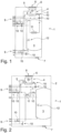
- FIG. 1 A hydraulic diagram of a room unit 1 with a housing 2 is shown schematically.
- a hot water tank 3 Within the housing 2 there is a hot water tank 3 and a heat exchanger 4 with a (finned) heat exchanger surface 5, wherein the heat exchanger 4 advantageously comprises a fan converter 6.
- the fan converter 6 With the fan converter 6, room air is sucked in through a lower inlet opening 7 of the housing 2 and directed to an upper outlet opening 8 and discharged from the housing 2.
- Drinking water, thermal energy, and wastewater are supplied to and removed from the room unit 1 via connections 9.
- Various valves 10, some of which are electrically/motorically controlled, are provided for advantageous hydraulic guidance or piping.
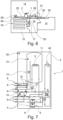
- a heat exchanger 11 is provided for heating the drinking water of the storage tank 3, e.g. as a coiled tube heat exchanger 11 according to Figure 1 or as plate heat exchanger 11 according to Figure 2
- an electric heating element 12 can optionally be provided for heating the drinking water in the storage tank 3.
- One of the heat exchangers 4 is designed as an optionally installable housing wall heater 40, which heats the (metallic) wall of the housing 2 and thus the room air.
- temperature sensors 30, 31 are shown schematically, with which the temperature of the drinking water storage tank 3 and the room air or the interior (through which room air can flow) of the housing 2 or the unit 1 can be determined and can be used advantageously for monitoring, controlling or regulating the heating system.
- the room unit 1 can advantageously be designed with switching between hot water operation and heating operation both by surface heating 40 and by two air-water heat exchangers 4 equipped with a compact fan 6 and connected hydraulically in parallel, which are designed, for example, in the form of finned tube heat exchangers 4.
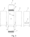
- a display 13 can be provided, with which, for example, the room unit 1 can be configured or parameterised (cf. Figure 3 ).
- FIG 4 An example of the installation and use of the room unit 1 in a two-room apartment is illustrated, which is used both for cooling and for heating the living room 14 and, if necessary, indirectly from adjacent rooms 15, for example by means of a ventilation fan 23, 24 or the like.
- a corridor/hallway 16 may not be heatable.
- one of the adjacent rooms 15 can be a bathroom/WC and, among other things, have a shower 17.
- the shower 17 draws its hot water from the room unit 1 in the living room 14 via corresponding water pipes, whereby, if necessary, an underfloor heating system 18 or heating loops in the floor of the bathroom 15 also receives heat energy from the room unit 1 and is advantageously connected to the room unit 1 via heating pipes/lines.
- FIG 4 Optionally installable and/or combinable (active, electric) blowers 23, 24 or so-called “overflow” 23, 24 or fans 23, 24 are schematically shown, which can be provided to increase or improve the air exchange or air movement in the apartment and thus to improve the heat supply to rooms 14, 15, 16. These can be installed optionally in a wall of room 14, 15, 16 and/or a door of room 14, 15, 16. Alternatively, the fans 23, 24 can also be designed as passive or pressure-controlled fan valves, through openings, or the like.
- the above-mentioned active transfer devices or fans 23, 24 advantageously enable air exchange with another room and thus, for example, maintain a living unit at a certain temperature level.
- active "transfer devices" 23, 24 or zone fans are already available on the market, but are currently mostly used only to improve indoor air quality by regulating CO2 levels and relative humidity, e.g., in rooms without windows or bathrooms.
- these or fans 23, 24 in general are advantageously used for heat distribution with selective heat input, without the use of a water- or air-guided piping system.
- the heat is distributed by the fans or ventilators 23, 24 installed in the doors/walls, which distribute or exchange the warm air and thus ensure that only one heating heat output is necessary per residential unit.
- a building 22 is shown schematically in a sectional side view, which has, for example, four floors or residential units/apartments, each with a separate/own room unit 1.
- the heat source 19 in the embodiment according to Figure 5 An air-source heat pump 19 (AHP) is used, which extracts heat energy from atmospheric air and supplies it to a (closed) heating circuit 20.
- the heating circuit 20 essentially comprises a heating flow line and a heating return line (two-pipe system), which supplies heat energy to each room unit 1 of each residential unit.
- a control unit 21 or a control device 21 is provided, which, among other things, includes the electronic/electrical control/regulation of the system.
- Figure 6 is similar or alternative to the variant according to Figure 4 a second, exemplary installation or use of the room unit 1 in a two-room apartment is illustrated, which is used both for cooling and for heating the living room 14 and here also directly from adjacent rooms 15, for example by means of heating pipes 26, ie heating flow and heating return.
- a corridor/hallway 16 may not be heated.
- one of the adjacent rooms 15 may be a bathroom/WC and, among other things, include a shower 17.
- the shower 17 draws its hot water from the room unit 1 of the living room 14 via a corresponding water pipe 25, whereas a sink 29 in the room 14 or the living/kitchen area 14 receives hot drinking water via a hot water pipe 25.
- underfloor heating 18 or heating loops in the floor of the bathroom 15 are provided, which also receives heat energy from the room unit 1 and is advantageously connected to the room unit 1 via heating pipes/lines 26. Additionally or optionally, the room 15 or a bedroom 15 has a so-called radiator 32 or heating element 32, which in turn receives heat energy via lines 26 from the room unit 1.
- a corresponding hydraulic circuit can be provided in a room unit 1 with a decentralised air-water heat pump 27 (cf. Figure 6 ), such as those used for renovation or in It can be used in new buildings.
- Room unit 1 serves as the indoor unit for the heat pump 27 and, in addition to space heating and cooling, hot water preparation, and heating circuit distribution, also advantageously controls the heat pump 27 via a bus system.
- Unit 1 is a so-called "all-in-one solution" for cost-effective renovation.
- the UWP, diaphragm expansion tank, and safety valve, etc., required for heating, can also be integrated.
- a control device 21 or the control unit 21 in the room unit 1 or on the separate or own energy source 27 or heat pump 27, e.g. outside on the outer wall of the apartment or building.
- a room unit 1 according to the invention is a complete solution for hot water preparation, heating, and cooling.
- the room unit 1 is advantageously designed as a heating and cooling center 1 in a residential unit, is installed directly in the living space 14, and releases heat there or extracts heat from the room, namely via an integrated heat exchanger 4, e.g., in the form of a fan coil unit 6 with heat exchanger surface 5 or the like.
- a so-called integrated register boiler 3 or, alternatively, a plate heat exchanger 11 with a hot water tank 3 generates and stores domestic hot water at specific times. Additional rooms 15 can be heated with hot water via the connection 9 of a heating circuit distributor or additional heat distributors. or cooled.
- An air-to-water heat pump, brine-to-water heat pump, gas heater, or district heating transfer station can be used as the energy source.
- the room unit 1 also advantageously offers the possibility of, for example, an integrated heat meter for automatic heating billing within a residential building.
- domestic hot water can be prepared electrically via an optional additional electric heating element 12 integrated in the water heater 3 as an additional heater or the like, e.g. with a photovoltaic system to use your own solar power or to increase the self-consumption of a PV system.
- the room unit 1 can be installed on a wall with the appropriate connecting cables or in the corner of a room. Air is preferably drawn in from the lower area/section of the room unit or at floor level (opening 7) and heated/cooled and discharged into the room from the upper or, if applicable, the middle area/section of the unit, either frontally or from the top or upper end of the unit, i.e., the top view surface (opening 8).
- the room temperature target and/or time programs, etc. can be advantageously set and, if necessary, energy consumption or other/additional data/information can be read.
- Additional room thermostats, etc. can be connected to a suitable control or monitoring unit, i.e., the so-called “electronics" of room unit 1.
- This "electronics" of room unit 1 For example, it distributes/controls the heating water accordingly in additional, optional heat distributors 18 of other rooms 15.
- the room units 1 can be operated with various heat/cooling generators 19. Brine-water heat pumps, air-water heat pumps 19, or other heat pumps are suitable for supplying heating and cooling water. For pure heating, district heating with a transfer station or a condensing boiler of any type can be used.
- a two-pipe system 20 is advantageously sufficient for all operating conditions, e.g., consisting of one heating flow and one heating return. This advantageously separates heating/cooling and hot water operation, e.g., two hours of hot water preparation per day, with heating/cooling operation in between. If hot water is insufficient in between, storage tank 3 or register boiler 3 can be advantageously reheated electrically (heating element 12). Due to the decentralized hot water preparation in the residential unit, a circulation line is not necessary, which saves both structural and financial effort.
- An advantageous control unit 21 is, for example, an electronic unit 21 in the part of the heat generator's hydraulics located in the house, which controls the heat generator and the room units 1 in each residential unit.
- the control unit 21 preferably communicates with the individual devices/components 1 via a bus system.
- an existing building management system can also be integrated via a bus system.
- the control unit 21 coordinates, among other things, the hot water preparation, which is temporally separate from the heating/cooling operation, with the individual Room units 1, e.g. hot water preparation twice a day, with heating or cooling operation in between.
- connection 9 of the device 1 is preferably made on the rear side of the housing 2, e.g. via eight connections described in the hydraulic plan (cf. Figures 1-3 ).
- a connection is established with the bus system to control unit 21 and an electrical power supply. Device 1 is then ready for operation.
- the advantageous apartment stations/room units 1 for hot water preparation and heating/cooling have the function of dissipating heat and cold into the installation room 14. They are installed as directly/immediately as possible in the building room 14 or living space 14 to be heated for optimal heat distribution.
- a system can be implemented, wherein the system advantageously consists of a control unit 21 and a plurality of room units 1.
- the control unit 21 is preferably an electronic control unit 21 and advantageously specifies to the individual room units 1 via a bus system (not shown in detail) whether they should hydraulically switch to hot water preparation mode or whether they can/should heat or cool depending on the room temperature.
- the control unit 21 or the control system also consists of a specially developed hydraulic circuit with several switching valves that, in combination with a heat pump, allow the following operating modes, for example:
- the hydraulic circuit ensures that storage tank 3 or buffer tank 3 can be loaded at different heights with heating water heated to different temperatures.
- buffer tank 3 is short-circuited or cold water is loaded into a separate cooling buffer tank.
- the room unit 1 is typically designed such that it does not generate heat; it does not contain a refrigeration unit; it does not utilize waste heat for heat recovery; instead, it utilizes the thermal energy contained in the heating water for hot water preparation and space heating.
- the hot water is (always) kept at >50°C, as otherwise hygiene standards would not be met.
- the integrated space heating in room unit 1 is supplied with heating water and not with refrigerant to heat rooms 14, 15, and 16.
- Room unit 1 generates hot water through hydraulic connection between the heat exchanger for space heating and the heat exchanger in the hot water tank, and not through the waste heat of a refrigeration circuit.
Landscapes
- Engineering & Computer Science (AREA)
- Chemical & Material Sciences (AREA)
- Combustion & Propulsion (AREA)
- Mechanical Engineering (AREA)
- General Engineering & Computer Science (AREA)
- Physics & Mathematics (AREA)
- Thermal Sciences (AREA)
- Life Sciences & Earth Sciences (AREA)
- Sustainable Development (AREA)
- Water Supply & Treatment (AREA)
- Steam Or Hot-Water Central Heating Systems (AREA)
Claims (12)
- Installation de production d'eau chaude potable avec au moins une pièce de bâtiment, avec au moins un raccord de sortie (17) tel qu'un robinet d'eau et/ou une tête de douche et avec une unité de production d'eau chaude potable (1) à placer/agencer dans la pièce de bâtiment (14) et pour produire de l'eau chaude potable avec un réservoir d'eau chaude potable (3) pour stocker et délivrer de l'eau potable, notamment de l'eau sanitaire, au raccord de sortie (17), au moins un dispositif d'échange de chaleur d'eau potable (11) étant prévu pour chauffer l'eau potable du réservoir d'eau chaude potable (3), au moins le réservoir d'eau chaude potable (3) et le dispositif d'échange de chaleur d'eau potable (11) étant agencés à l'intérieur d'un boîtier (2) et/ou d'une enveloppe (2), au moins une surface de chauffage (5) de la pièce de bâtiment étant prévue au moins sur le boîtier (2) et/ou l'enveloppe (2) pour chauffer/réchauffer la pièce de bâtiment (14), le boîtier (2) et/ou l'enveloppe (2) comprenant au moins une ouverture d'entrée d'air (7) pour l'entrée d'air ambiant de la pièce de bâtiment (14) et au moins une ouverture de sortie d'air (8) pour la sortie d'air ambiant dans la pièce de bâtiment (14), l'unité de production d'eau chaude sanitaire (1) étant réalisée sous forme d'élément de chauffage de pièce de la pièce de bâtiment/pièce d'habitation (14), au moins une unité de refroidissement (4, 19) étant prévue pour refroidir une surface de refroidissement (5), la surface de chauffage de pièce de bâtiment (5) étant réalisée sous la forme de la surface de refroidissement (5) de l'unité de refroidissement (4, 19) et la pièce de bâtiment (14) étant réalisée sous forme de pièce d'habitation (14), de telle sorte que l'unité de production d'eau chaude potable est placée/agencée dans la pièce d'habitation (14, 15, 16), et le raccord de sortie étant agencé dans une pièce de cuisine (14) et/ou une salle de bain/d'eau (14, 15) et/ou une pièce de toilettes (14, 15).
- Installation de production d'eau chaude potable selon la revendication 1, caractérisée en ce qu'au moins une unité d'échange de chaleur d'eau de chauffage (4) comprend la surface de chauffage de pièce de bâtiment (5), l'unité d'échange de chaleur d'eau de chauffage (4) étant agencée à l'intérieur du boîtier (2) et/ou de l'enveloppe (2).
- Installation de production d'eau chaude potable selon l'une quelconque des revendications précédentes, caractérisée en ce qu'au moins une unité de chauffage (19) est prévue pour chauffer la surface de chauffage de pièce de bâtiment (5).
- Installation de production d'eau chaude potable selon la revendication 3, caractérisée en ce que l'unité de chauffage (19) est réalisée sous forme d'appareil séparé (19) et/ou est agencée dans un boîtier d'appareil séparé.
- Installation de production d'eau chaude potable selon la revendication 3 ou 4, caractérisée en ce que l'unité de chauffage est réalisée sous forme de source d'énergie externe pour produire de l'énergie thermique, de telle sorte qu'au moins le réservoir d'eau chaude potable (3) et le dispositif d'échange de chaleur d'eau potable (11) peuvent être chauffés par l'énergie thermique de la source d'énergie externe/l'unité de chauffage.
- Installation de production d'eau chaude potable selon l'une quelconque des revendications 3 à 5, caractérisée en ce qu'une unité de fluide de chauffage et/ou au moins deux conduites de fluide de chauffage sont prévues/agencées entre le boîtier/l'enveloppe (2) et l'unité de chauffage (19) et/ou l'appareil séparé (19) et/ou le boîtier d'appareil séparé.
- Installation de production d'eau chaude potable selon la revendication 2, caractérisée en ce que l'unité d'échange de chaleur d'eau de chauffage est réalisée sous forme d'unité de refroidissement.
- Installation de production d'eau chaude potable selon l'une quelconque des revendications 3 à 6, caractérisée en ce qu'au moins l'unité de chauffage est réalisée pour produire de l'énergie de chauffage pour la pièce de bâtiment et/ou pour l'eau chaude potable du réservoir d'eau chaude potable et/ou en ce qu'au moins une unité de refroidissement est prévue pour refroidir une surface de refroidissement et/ou la pièce de bâtiment.
- Installation de production d'eau chaude potable selon l'une quelconque des revendications 3 à 6 ou 8, caractérisée en ce qu'au moins une unité de pompe à chaleur comprend l'unité de chauffage et/ou l'unité de refroidissement.
- Installation de production d'eau chaude potable selon la revendication 9, caractérisée en ce que l'unité de pompe à chaleur présente un boîtier de pompe à chaleur, des conduites de fluide, notamment des conduites d'eau, d'un circuit de chauffage et/ou de refroidissement étant prévues entre l'unité de pompe à chaleur et l'unité de production d'eau chaude potable et/ou le boîtier, l'unité de pompe à chaleur étant notamment agencée au moins partiellement sur une enveloppe extérieure telle qu'un mur extérieur et/ou un toit de bâtiment du bâtiment et/ou dans une chaufferie et/ou une cave du bâtiment.
- Installation de production d'eau chaude potable selon l'une quelconque des revendications précédentes, caractérisée en ce qu'un bâtiment présente plusieurs unités d'habitation/habitations avec au moins une pièce de bâtiment et/ou une pièce d'habitation (14), chacune des plusieurs unités d'habitation/habitations (14) présentant respectivement une unité de production d'eau chaude potable (1) et respectivement une unité de chauffage d'habitation (19) et/ou une unité de pompe à chaleur d'habitation (19) et/ou une unité de refroidissement d'habitation (19) réalisée sous forme de l'unité de chauffage (19) et/ou d'un appareil séparé (19) et/ou d'une source d'énergie externe (19).
- Installation de production d'eau chaude potable selon l'une quelconque des revendications précédentes, caractérisée en ce qu'un bâtiment présente plusieurs unités d'habitation/habitations (14) avec au moins une pièce de bâtiment et/ou une pièce d'habitation (14), chacune des plusieurs unités d'habitation/habitations (14) présentant respectivement une unité de production d'eau chaude potable (1), et une unité de chauffage (19) unique/commune et/ou une unité de pompe à chaleur (19) et/ou une unité de refroidissement (19) réalisée sous forme de l'unité de chauffage (19) et/ou d'un appareil séparé (19) et/ou d'une source d'énergie externe (19) étant notamment prévue pour les unités de production d'eau chaude potable des plusieurs unités d'habitation/habitations.
Applications Claiming Priority (1)
| Application Number | Priority Date | Filing Date | Title |
|---|---|---|---|
| DE102021111725.9A DE102021111725A1 (de) | 2021-05-05 | 2021-05-05 | Trinkwarmwasser-Erzeugungseinheit zum Erzeugen von Trinkwarmwasser |
Publications (3)
| Publication Number | Publication Date |
|---|---|
| EP4086524A1 EP4086524A1 (fr) | 2022-11-09 |
| EP4086524C0 EP4086524C0 (fr) | 2025-04-23 |
| EP4086524B1 true EP4086524B1 (fr) | 2025-04-23 |
Family
ID=81975250
Family Applications (1)
| Application Number | Title | Priority Date | Filing Date |
|---|---|---|---|
| EP22171751.5A Active EP4086524B1 (fr) | 2021-05-05 | 2022-05-05 | Installation de production d'eau chaude potable |
Country Status (2)
| Country | Link |
|---|---|
| EP (1) | EP4086524B1 (fr) |
| DE (1) | DE102021111725A1 (fr) |
Families Citing this family (3)
| Publication number | Priority date | Publication date | Assignee | Title |
|---|---|---|---|---|
| EP4680900A1 (fr) * | 2023-03-16 | 2026-01-21 | SAM 365 GmbH | Système de technologie domestique, groupe de systèmes de technologie domestique et procédé de commande d'un système de technologie domestique et/ou d'un groupe de systèmes de technologie domestique |
| DE102024001366A1 (de) * | 2024-04-27 | 2025-10-30 | Hansa Heiztechnik GmbH | Wärmemanagementsystem zur Verbindung mit einer Wärmepumpe, betreffendes Heizungssystem und Verwendung |
| DE102024112757A1 (de) * | 2024-05-07 | 2025-11-13 | Vaillant Gmbh | Verfahren zur Umrüstung einer Altheizungsanlage, Verfahren zum Betreiben einer Wärmepumpenanlage, Wärmepumpenanlage und Computerprogrammprodukt |
Family Cites Families (7)
| Publication number | Priority date | Publication date | Assignee | Title |
|---|---|---|---|---|
| DE19702903C2 (de) * | 1997-01-28 | 2000-08-24 | Stiebel Eltron Gmbh & Co Kg | Klimaanlage mit einer Wärmepumpe |
| DE19724151A1 (de) | 1997-06-07 | 1998-12-10 | Gaggenau Hausgeraete Gmbh | Kühlgerät für den Haushalt |
| DE10065216B4 (de) | 2000-12-23 | 2005-01-20 | Stiebel Eltron Gmbh & Co. Kg | Regeleinrichtung eines zentralen Lüftungsgeräts |
| DE10142779A1 (de) | 2001-08-31 | 2003-03-27 | Viessmann Werke Kg | Kompaktheizgerät |
| AT502029B1 (de) | 2005-06-09 | 2007-01-15 | Drexel Und Weiss Energieeffizi | Einrichtung zur belüftung und beheizung von gebäuden |
| DE102006019175B4 (de) | 2006-04-21 | 2008-05-08 | Stiebel Eltron Gmbh & Co. Kg | Wärmepumpenvorrichtung |
| EP3696475B9 (fr) | 2019-02-14 | 2025-02-26 | R. Nussbaum AG | Dispositif de fourniture d'eau chaude de consommation |
-
2021
- 2021-05-05 DE DE102021111725.9A patent/DE102021111725A1/de not_active Withdrawn
-
2022
- 2022-05-05 EP EP22171751.5A patent/EP4086524B1/fr active Active
Also Published As
| Publication number | Publication date |
|---|---|
| EP4086524A1 (fr) | 2022-11-09 |
| EP4086524C0 (fr) | 2025-04-23 |
| DE102021111725A1 (de) | 2022-11-10 |
Similar Documents
| Publication | Publication Date | Title |
|---|---|---|
| EP4086524B1 (fr) | Installation de production d'eau chaude potable | |
| US8122944B2 (en) | Combined potable water-surface heating and cooling system | |
| DE212018000133U1 (de) | Kombiniertes System aus einer Brauchwassererwärmung und einem Heizmedium zur Wohnungsheizung | |
| DE102020111984B4 (de) | Modulares Wärmepumpensystem | |
| DE202014001131U1 (de) | Vorrichtung zur Trinkwasserversorgung für Kalt- und Warmwasser mit Wärmepumpe | |
| US10612792B2 (en) | Air conditioning system, peripheral air-conditioning unit thereof and water pipeline upgrading method for heating purposes | |
| CH708598A1 (de) | Anordnung und Verfahren zum Raumtemperieren und Warmwasserbereitstellen. | |
| EP3444538B1 (fr) | Installation technique domestique | |
| EP0647818B1 (fr) | Système de chauffage décentralisé dans lequel usage est fait de techniques de conduites d'écoulement multiples | |
| DE29715834U1 (de) | Einrichtung zur Klimatisierung und Warmwasserbereitung | |
| DE10315802B4 (de) | Anordnung zur Versorgung von Räumen eines Gebäudes mit temperierter Luft | |
| DE20216395U1 (de) | Lüftungsgerät insbesondere für Niedrigenergiehäuser | |
| DE10015581C1 (de) | Innenraum-Klimatisierungsvorrichtung | |
| DE202014104134U1 (de) | Wohnungsstation | |
| DE60008780T2 (de) | Modularer gasbeheizter kombikessel | |
| EP1462734A1 (fr) | Installation technique domestique | |
| DE202007010849U1 (de) | Heizungssystem | |
| DE10149339C1 (de) | Heizungsanlage für ein Gebäude, insbesondere für ein Wohnhaus | |
| DE20318592U1 (de) | Hauskühlung | |
| DE102024117297A1 (de) | Raummodul für ein Gebäude, insbesondere mit einem Bad, einer Toilette, einem Hauswirtschaftsraum, einem Hausanschlussraum oder Kombinationen davon | |
| DE102018007496B4 (de) | Versorgungsvorrichtung zur Versorgung einer Nutzungseinheit mit Wärme, Kälte, Warmwasser und/oder Luft und Verfahren zum Austausch einer Versorgungsvorrichtung an einem Gebäude oder Raum | |
| DE10148585A1 (de) | Einzelraum-Heizsystem | |
| EP4722605A1 (fr) | Système de thermorégulation de l'eau d'une unité d'utilisation et dispositif de thermorégulation de l'eau associé | |
| DE202023001028U1 (de) | Heizgerät und/oder Kühlgerät | |
| AT18659U1 (de) | Wärmepumpenmodul und Gebäudeklimasystem |
Legal Events
| Date | Code | Title | Description |
|---|---|---|---|
| PUAI | Public reference made under article 153(3) epc to a published international application that has entered the european phase |
Free format text: ORIGINAL CODE: 0009012 |
|
| STAA | Information on the status of an ep patent application or granted ep patent |
Free format text: STATUS: THE APPLICATION HAS BEEN PUBLISHED |
|
| AK | Designated contracting states |
Kind code of ref document: A1 Designated state(s): AL AT BE BG CH CY CZ DE DK EE ES FI FR GB GR HR HU IE IS IT LI LT LU LV MC MK MT NL NO PL PT RO RS SE SI SK SM TR |
|
| STAA | Information on the status of an ep patent application or granted ep patent |
Free format text: STATUS: REQUEST FOR EXAMINATION WAS MADE |
|
| 17P | Request for examination filed |
Effective date: 20230320 |
|
| RBV | Designated contracting states (corrected) |
Designated state(s): AL AT BE BG CH CY CZ DE DK EE ES FI FR GB GR HR HU IE IS IT LI LT LU LV MC MK MT NL NO PL PT RO RS SE SI SK SM TR |
|
| RAP3 | Party data changed (applicant data changed or rights of an application transferred) |
Owner name: REKS GMBH |
|
| GRAP | Despatch of communication of intention to grant a patent |
Free format text: ORIGINAL CODE: EPIDOSNIGR1 |
|
| STAA | Information on the status of an ep patent application or granted ep patent |
Free format text: STATUS: GRANT OF PATENT IS INTENDED |
|
| INTG | Intention to grant announced |
Effective date: 20241025 |
|
| GRAJ | Information related to disapproval of communication of intention to grant by the applicant or resumption of examination proceedings by the epo deleted |
Free format text: ORIGINAL CODE: EPIDOSDIGR1 |
|
| STAA | Information on the status of an ep patent application or granted ep patent |
Free format text: STATUS: REQUEST FOR EXAMINATION WAS MADE |
|
| GRAP | Despatch of communication of intention to grant a patent |
Free format text: ORIGINAL CODE: EPIDOSNIGR1 |
|
| STAA | Information on the status of an ep patent application or granted ep patent |
Free format text: STATUS: GRANT OF PATENT IS INTENDED |
|
| INTC | Intention to grant announced (deleted) | ||
| INTG | Intention to grant announced |
Effective date: 20250116 |
|
| GRAS | Grant fee paid |
Free format text: ORIGINAL CODE: EPIDOSNIGR3 |
|
| GRAA | (expected) grant |
Free format text: ORIGINAL CODE: 0009210 |
|
| STAA | Information on the status of an ep patent application or granted ep patent |
Free format text: STATUS: THE PATENT HAS BEEN GRANTED |
|
| AK | Designated contracting states |
Kind code of ref document: B1 Designated state(s): AL AT BE BG CH CY CZ DE DK EE ES FI FR GB GR HR HU IE IS IT LI LT LU LV MC MK MT NL NO PL PT RO RS SE SI SK SM TR |
|
| REG | Reference to a national code |
Ref country code: GB Ref legal event code: FG4D Free format text: NOT ENGLISH |
|
| REG | Reference to a national code |
Ref country code: CH Ref legal event code: EP |
|
| REG | Reference to a national code |
Ref country code: DE Ref legal event code: R096 Ref document number: 502022003635 Country of ref document: DE |
|
| REG | Reference to a national code |
Ref country code: IE Ref legal event code: FG4D Free format text: LANGUAGE OF EP DOCUMENT: GERMAN |
|
| U01 | Request for unitary effect filed |
Effective date: 20250522 |
|
| U07 | Unitary effect registered |
Designated state(s): AT BE BG DE DK EE FI FR IT LT LU LV MT NL PT RO SE SI Effective date: 20250602 |
|
| U20 | Renewal fee for the european patent with unitary effect paid |
Year of fee payment: 4 Effective date: 20250526 |
|
| PG25 | Lapsed in a contracting state [announced via postgrant information from national office to epo] |
Ref country code: ES Free format text: LAPSE BECAUSE OF FAILURE TO SUBMIT A TRANSLATION OF THE DESCRIPTION OR TO PAY THE FEE WITHIN THE PRESCRIBED TIME-LIMIT Effective date: 20250423 |
|
| PG25 | Lapsed in a contracting state [announced via postgrant information from national office to epo] |
Ref country code: GR Free format text: LAPSE BECAUSE OF FAILURE TO SUBMIT A TRANSLATION OF THE DESCRIPTION OR TO PAY THE FEE WITHIN THE PRESCRIBED TIME-LIMIT Effective date: 20250724 Ref country code: NO Free format text: LAPSE BECAUSE OF FAILURE TO SUBMIT A TRANSLATION OF THE DESCRIPTION OR TO PAY THE FEE WITHIN THE PRESCRIBED TIME-LIMIT Effective date: 20250723 |
|
| PG25 | Lapsed in a contracting state [announced via postgrant information from national office to epo] |
Ref country code: PL Free format text: LAPSE BECAUSE OF FAILURE TO SUBMIT A TRANSLATION OF THE DESCRIPTION OR TO PAY THE FEE WITHIN THE PRESCRIBED TIME-LIMIT Effective date: 20250423 |
|
| PG25 | Lapsed in a contracting state [announced via postgrant information from national office to epo] |
Ref country code: HR Free format text: LAPSE BECAUSE OF FAILURE TO SUBMIT A TRANSLATION OF THE DESCRIPTION OR TO PAY THE FEE WITHIN THE PRESCRIBED TIME-LIMIT Effective date: 20250423 |
|
| PG25 | Lapsed in a contracting state [announced via postgrant information from national office to epo] |
Ref country code: RS Free format text: LAPSE BECAUSE OF FAILURE TO SUBMIT A TRANSLATION OF THE DESCRIPTION OR TO PAY THE FEE WITHIN THE PRESCRIBED TIME-LIMIT Effective date: 20250723 |
|
| PG25 | Lapsed in a contracting state [announced via postgrant information from national office to epo] |
Ref country code: IS Free format text: LAPSE BECAUSE OF FAILURE TO SUBMIT A TRANSLATION OF THE DESCRIPTION OR TO PAY THE FEE WITHIN THE PRESCRIBED TIME-LIMIT Effective date: 20250823 |
|
| REG | Reference to a national code |
Ref country code: CH Ref legal event code: H13 Free format text: ST27 STATUS EVENT CODE: U-0-0-H10-H13 (AS PROVIDED BY THE NATIONAL OFFICE) Effective date: 20251223 |
|
| PG25 | Lapsed in a contracting state [announced via postgrant information from national office to epo] |
Ref country code: SM Free format text: LAPSE BECAUSE OF FAILURE TO SUBMIT A TRANSLATION OF THE DESCRIPTION OR TO PAY THE FEE WITHIN THE PRESCRIBED TIME-LIMIT Effective date: 20250423 |
|
| PG25 | Lapsed in a contracting state [announced via postgrant information from national office to epo] |
Ref country code: CH Free format text: LAPSE BECAUSE OF NON-PAYMENT OF DUE FEES Effective date: 20250531 |
|
| PG25 | Lapsed in a contracting state [announced via postgrant information from national office to epo] |
Ref country code: CZ Free format text: LAPSE BECAUSE OF FAILURE TO SUBMIT A TRANSLATION OF THE DESCRIPTION OR TO PAY THE FEE WITHIN THE PRESCRIBED TIME-LIMIT Effective date: 20250423 |
|
| PG25 | Lapsed in a contracting state [announced via postgrant information from national office to epo] |
Ref country code: SK Free format text: LAPSE BECAUSE OF FAILURE TO SUBMIT A TRANSLATION OF THE DESCRIPTION OR TO PAY THE FEE WITHIN THE PRESCRIBED TIME-LIMIT Effective date: 20250423 |
|
| PG25 | Lapsed in a contracting state [announced via postgrant information from national office to epo] |
Ref country code: MC Free format text: LAPSE BECAUSE OF FAILURE TO SUBMIT A TRANSLATION OF THE DESCRIPTION OR TO PAY THE FEE WITHIN THE PRESCRIBED TIME-LIMIT Effective date: 20250423 |
|
| PLBE | No opposition filed within time limit |
Free format text: ORIGINAL CODE: 0009261 |
|
| STAA | Information on the status of an ep patent application or granted ep patent |
Free format text: STATUS: NO OPPOSITION FILED WITHIN TIME LIMIT |
|
| REG | Reference to a national code |
Ref country code: CH Ref legal event code: L10 Free format text: ST27 STATUS EVENT CODE: U-0-0-L10-L00 (AS PROVIDED BY THE NATIONAL OFFICE) Effective date: 20260304 |
|
| 26N | No opposition filed |
Effective date: 20260126 |
|
| PG25 | Lapsed in a contracting state [announced via postgrant information from national office to epo] |
Ref country code: IE Free format text: LAPSE BECAUSE OF NON-PAYMENT OF DUE FEES Effective date: 20250505 |