EP4092645A1 - Augmentation de la puissance d'aspiration pour un détecteur de fumée par aspiration (asd) permettant de réduire le temps de transport à une valeur de niveau de signal minimum détecté sans émettre de message d'interruption - Google Patents
Augmentation de la puissance d'aspiration pour un détecteur de fumée par aspiration (asd) permettant de réduire le temps de transport à une valeur de niveau de signal minimum détecté sans émettre de message d'interruption Download PDFInfo
- Publication number
- EP4092645A1 EP4092645A1 EP22159123.3A EP22159123A EP4092645A1 EP 4092645 A1 EP4092645 A1 EP 4092645A1 EP 22159123 A EP22159123 A EP 22159123A EP 4092645 A1 EP4092645 A1 EP 4092645A1
- Authority
- EP
- European Patent Office
- Prior art keywords
- air flow
- intake
- value
- fire
- control unit
- Prior art date
- Legal status (The legal status is an assumption and is not a legal conclusion. Google has not performed a legal analysis and makes no representation as to the accuracy of the status listed.)
- Granted
Links
Images
Classifications
-
- G—PHYSICS
- G08—SIGNALLING
- G08B—SIGNALLING SYSTEMS, e.g. PERSONAL CALLING SYSTEMS; ORDER TELEGRAPHS; ALARM SYSTEMS
- G08B17/00—Fire alarms; Alarms responsive to explosion
- G08B17/10—Actuation by presence of smoke or gases, e.g. automatic alarm devices for analysing flowing fluid materials by the use of optical means
-
- G—PHYSICS
- G01—MEASURING; TESTING
- G01N—INVESTIGATING OR ANALYSING MATERIALS BY DETERMINING THEIR CHEMICAL OR PHYSICAL PROPERTIES
- G01N1/00—Sampling; Preparing specimens for investigation
- G01N1/02—Devices for withdrawing samples
- G01N1/22—Devices for withdrawing samples in the gaseous state
- G01N1/24—Suction devices
-
- G—PHYSICS
- G05—CONTROLLING; REGULATING
- G05B—CONTROL OR REGULATING SYSTEMS IN GENERAL; FUNCTIONAL ELEMENTS OF SUCH SYSTEMS; MONITORING OR TESTING ARRANGEMENTS FOR SUCH SYSTEMS OR ELEMENTS
- G05B15/00—Systems controlled by a computer
- G05B15/02—Systems controlled by a computer electric
-
- G—PHYSICS
- G08—SIGNALLING
- G08B—SIGNALLING SYSTEMS, e.g. PERSONAL CALLING SYSTEMS; ORDER TELEGRAPHS; ALARM SYSTEMS
- G08B17/00—Fire alarms; Alarms responsive to explosion
- G08B17/10—Actuation by presence of smoke or gases, e.g. automatic alarm devices for analysing flowing fluid materials by the use of optical means
- G08B17/11—Actuation by presence of smoke or gases, e.g. automatic alarm devices for analysing flowing fluid materials by the use of optical means using an ionisation chamber for detecting smoke or gas
- G08B17/113—Constructional details
-
- G—PHYSICS
- G08—SIGNALLING
- G08B—SIGNALLING SYSTEMS, e.g. PERSONAL CALLING SYSTEMS; ORDER TELEGRAPHS; ALARM SYSTEMS
- G08B25/00—Alarm systems in which the location of the alarm condition is signalled to a central station, e.g. fire or police telegraphic systems
- G08B25/01—Alarm systems in which the location of the alarm condition is signalled to a central station, e.g. fire or police telegraphic systems characterised by the transmission medium
- G08B25/08—Alarm systems in which the location of the alarm condition is signalled to a central station, e.g. fire or police telegraphic systems characterised by the transmission medium using communication transmission lines
-
- G—PHYSICS
- G08—SIGNALLING
- G08B—SIGNALLING SYSTEMS, e.g. PERSONAL CALLING SYSTEMS; ORDER TELEGRAPHS; ALARM SYSTEMS
- G08B25/00—Alarm systems in which the location of the alarm condition is signalled to a central station, e.g. fire or police telegraphic systems
- G08B25/01—Alarm systems in which the location of the alarm condition is signalled to a central station, e.g. fire or police telegraphic systems characterised by the transmission medium
- G08B25/10—Alarm systems in which the location of the alarm condition is signalled to a central station, e.g. fire or police telegraphic systems characterised by the transmission medium using wireless transmission systems
-
- G—PHYSICS
- G08—SIGNALLING
- G08B—SIGNALLING SYSTEMS, e.g. PERSONAL CALLING SYSTEMS; ORDER TELEGRAPHS; ALARM SYSTEMS
- G08B29/00—Checking or monitoring of signalling or alarm systems; Prevention or correction of operating errors, e.g. preventing unauthorised operation
- G08B29/02—Monitoring continuously signalling or alarm systems
- G08B29/04—Monitoring of the detection circuits
- G08B29/043—Monitoring of the detection circuits of fire detection circuits
-
- G—PHYSICS
- G08—SIGNALLING
- G08B—SIGNALLING SYSTEMS, e.g. PERSONAL CALLING SYSTEMS; ORDER TELEGRAPHS; ALARM SYSTEMS
- G08B29/00—Checking or monitoring of signalling or alarm systems; Prevention or correction of operating errors, e.g. preventing unauthorised operation
- G08B29/12—Checking intermittently signalling or alarm systems
- G08B29/14—Checking intermittently signalling or alarm systems checking the detection circuits
- G08B29/145—Checking intermittently signalling or alarm systems checking the detection circuits of fire detection circuits
Definitions
- the invention relates to a method for operating an aspirating smoke detector, such an aspirating smoke detector and a computer program product for carrying out the operating method according to the invention.
- an aspirating smoke detector such an aspirating smoke detector
- a computer program product for carrying out the operating method according to the invention.
- aspirating smoke detectors or aspirating fire detectors are also referred to as ASD (for Aspirated Smoke Detector) in technical jargon.
- the aspirating smoke detector is provided for detecting a fire in a room to be monitored and for outputting a fire alarm if a fire is detected, typically to a fire alarm control panel (BMZ).
- room air is sucked in by means of a suction unit of the aspirating smoke detector via a suction pipe of the aspirating smoke detector provided with suction openings for smoke to be detected or for combustion gas to be detected and supplied to a fire detector unit of the aspirating smoke detector for metrological determination of a signal level of a fire parameter.
- the suction capacity of the suction unit for generating an air flow through the suction pipe is adjusted to a nominal air flow value for normal operation, i.e. to a nominal air flow value provided for normal operation.
- the suction power is increased from a minimum signal level value of the signal level in order to shorten the transport time of sucked room air with smoke and/or fire gas through the suction pipe to the fire detector unit.
- the aspirating smoke detector considered here comprises at least one fire detector unit for the metrological determination of a signal level of a fire parameter, an aspirating unit, a power control unit for adjusting the aspirating power of the aspirating unit and a connected to the aspirating unit, Intake pipe provided with intake openings for intake of room air with smoke and/or fire gas to be detected.
- the aspirating smoke detector also includes an air flow meter, in particular a flow meter, for detecting an air flow of the aspirated room air and an electronic control unit connected to the fire detector unit, to the air flow meter and to the power control unit.
- the latter is set up to set the intake power of the intake unit to a nominal air flow value for normal operation using the power control unit, to increase the intake power from a minimum signal level value using the power control unit to shorten the transport time and to issue a fire alarm if a fire is detected.
- the suction unit and the fire detector unit typically form a structural unit.
- Such a method and such an aspirating smoke detector are from EP 2 244 236 A1 known.
- By increasing the fan speed and thus increasing the suction power the transport time of sucked room air with smoke through the suction pipe to the fire detector unit is reduced. This enables faster fire detection.
- Normal operation means fire-free or smoke-free normal operation. It is available, for example, after commissioning or after maintenance of an aspirating smoke detector.
- intake pipe generally refers to a pipe system or also a hose system.
- the intake pipe can comprise a single pipe, preferably made of a plastic, or several partial pipes, which are split up by means of a pipe distributor, for example.
- the suction tube typically has a circular cross-section with a diameter in the range 1 cm to 5 cm, preferably in the range 2 cm to 3 cm.
- the intake pipe has a minimum pipe length of 30 m, preferably 50 m.
- a large number of intake openings are present or introduced along the intake pipe. They may be spaced an equal distance along the intake pipe, such as 4m to 8m apart.
- the signal level of a fire parameter to be determined by measurement is typically a concentration level or a concentration value of detected smoke or of a detected fire gas as a possible fire parameter.
- Smoke contains smoke particles of different particle sizes, which are also referred to as smoke aerosols.
- a typical fire gas is, for example, carbon monoxide or ammonia.
- the fire detector unit can have an optical detector unit, such as, for example, according to the scattered light principle or according to the transmitted light principle, or a gas sensor that is sensitive to fire gases, such as, for example, a CO gas sensor.
- the minimum signal level value is in particular dimensioned in such a way that there is a sufficiently high probability of a possible fire event, ie it is significant for a possible fire event.
- the determination of the minimum signal level value can be based on empirical values from a similar fire monitoring environment or can be carried out by means of an on-site fire test.
- the signal level of a fire parameter to be determined by measurement is typically a concentration level or a concentration value of detected smoke or of a detected fire gas as a possible fire parameter.
- the minimum signal level value is dimensioned in such a way that there is a sufficiently high probability of a possible fire event, i.e. it is significant for a possible fire event.
- the suction unit - typically a fan - and the fire detector unit are usually, but not necessarily, housed in a common housing as a unit. Seen in the direction of flow, the suction unit can be upstream or downstream of the fire detector unit.
- the fire detector unit can have an optical detector unit based on the principle of scattered light or transmitted light and/or a gas sensor unit for fire gases.
- Aspirating smoke detectors usually have a fan (aspirator). This extracts air samples from rooms via an intake pipe and feeds them to a fire detector unit.
- the intake pipes can extend over several 100 m. Aspirated smoke must therefore be detected over the entire length up to the fire detector unit.
- the time required for this is also referred to as dead time or transport time.
- the transport time can be in the range of minutes.
- the maximum transport time for a pipe length of 200 m, an average flow rate of 1 m/s and smoke suction at a pipe end remote from the fire detector unit is 200 seconds.
- An "ASD planner” usually calculates the essential parameters so that an aspirating smoke detector meets the relevant standards, such as the relevant European standard EN 54-20, here in the version of February 2009 that is valid at the time of the present patent application, or the for North America relevant standard UL268, preferably from the 6th or 7th edition.
- Various parameters play a role here, such as the length of the pipe, the size of the room, the number of suction openings, the suction pressure and the sensitivity of the fire detector unit.
- Various software-supported project planning tools are known for the technical design of an aspirating smoke detector, such as the ASYST project planning tool from Siemens. As soon as the parameters have been determined, a technician assembles the intake pipe, drills intake openings in the form of holes in the intake pipe and configures the fire detector unit according to the specifications.
- the intake power of the fan is also adjusted via the set speed in order to set an air flow with a nominal air flow value through the intake pipe. This speed then remains constant over the lifetime of the detector in smoke- and fire-free normal operation.
- an aspirating smoke detector is parameterized with a low fan speed in order to extend its service life and to minimize the noise level during aspiration.
- the reason for the static setting is the detection of interruptions with an associated increase in the air flow or the detection of blockages in the aspiration openings due to dirt with an associated decrease in the air flow over the course of the operating time of the aspirating smoke detector.
- the aspirating smoke detector must issue a fault within a period of 300 seconds specified in the standard.
- the UL268 standard preferably from the 6th or 7th edition, 90 seconds apply instead of the aforementioned 300 seconds.
- the nominal airflow value measured in liters per second or in liters per minute, is typically set when an aspirating smoke detector is commissioned.
- EP 2 407 946 A1 it is an object of the present invention to specify an improved method for operating an aspirating smoke detector. Another object of the invention is to specify a more reliable method for operating an aspirating smoke detector.
- Another object of the invention is to specify an improved aspirating smoke detector. Finally, it is an object of the invention to specify an aspirating smoke detector that works more reliably during operation.
- an interruption message is output for the method in fire-free or smoke-free normal operation if the air flow exceeds an upper limit value for a minimum period of time.
- the intake capacity is increased from the minimum signal level value, i.e. when the minimum signal level value is exceeded, in particular to shorten the transport time, only to the extent that the air flow does not exceed the upper limit value, or the intake capacity is increased from the minimum signal level value, i.e. when it is exceeded of the minimum signal level value, in particular to shorten the transport time, only for a period less than the minimum period in which the air flow exceeds the upper limit value.
- the suction power for shortening the transportation time is used only within the minimum period increased so that the airflow exceeds the upper limit.
- the purposeful performance-related and possibly time-limited increase in the suction performance advantageously means that, in addition to the fire detection that is possible more quickly, the output of a false interruption message is suppressed. An unnecessary inspection of the aspirating smoke detector by a service specialist is avoided. Nevertheless, the method according to the invention does not impair the monitoring of the aspirating smoke detector for an interruption and blockage, which is prescribed in the exemplary standard described at the outset and works independently of the fire detection.
- the intake power is only increased in such a way that the air flow does not or just not exceed the nominal air flow value, this increase is in principle not limited in time. In practice, however, regardless of whether a fire event is detected or not, preferably after a specified waiting time has elapsed, such as e.g. after 10, 20 or 30 minutes, the intake power is reduced again in such a way that the air flow again reaches the nominal air flow value.
- the intake power is increased in such a way that the air flow exceeds the nominal air flow value, for example by 1.2 to 5 times, preferably by 2 to 3 times, the interruption message is still not output if this increase is limited to the minimum period of time from the time the upper limit is exceeded.
- the intake capacity of the intake unit is reduced in such a way that the air flow falls below the upper limit value again.
- the intake power is reduced in particular in a period of 1 s to 20 s, preferably of 5 s to 10 s, before the end of the minimum period of time. This resets a timer in the control of the aspirating smoke detector. It is then possible to start increasing the intake power above the upper limit value again without the interruption message being output.
- the suction capacity of the suction unit is increased to shorten the transport time in such a way that the air flow does not exceed the upper limit value, or the suction capacity is only increased for a period of time that is less than the minimum period of time, in which the air flow exceeds the upper limit value, namely when a warning message, in particular a caution or attention signal, is received from a higher-level fire alarm control panel or control center, e.g. via a detector or bus line which connects the higher-level fire control panel or control center with the aspirating smoke detector.
- the connection between the aspirating smoke detector and the fire alarm control panel or control center can be wireless, e.g. via a WLAN, Bluetooth or a mobile 3G, 4G or 5G data connection.
- the aforementioned (data) connections can also be based on an Internet protocol.
- the fire alarm control panel or the control center can also be implemented as a cloud application in a cloud infrastructure.
- the aspirating smoke detector can receive the warning message "via the cloud" from a higher-level cloud fire alarm control panel or cloud control center.
- the warning message is issued if, for example, at least one other aspirating smoke detector is in the vicinity of this aspirating smoke detector a fire alarm or an impending fire has already been reported to the fire alarm control panel or the control center, for example in the form of a pre-alarm.
- the local correlation increases the probability of an actual fire in the vicinity of the installed aspirating smoke detector. In this case, an "anticipatory" increase in suction power is justified for the earliest possible fire detection.
- a blockage message is issued if the air flow falls below a lower limit value for a minimum period of time.
- the upper limit value for the air flow is set at 1.2 times the nominal air flow value.
- the lower limit value for the air flow is set in particular at 0.8 times the nominal air flow value.
- the minimum time period is set in particular to a value in the range from 60 seconds to 600 seconds, preferably to a value of 90 seconds or 300 seconds or to a value of 90 seconds ⁇ 3 seconds or 300 seconds ⁇ 3 seconds.
- the upper and lower limit values for the air flow in relation to the nominal air flow value and a duration value for the minimum period are specified by a national, regional or international standard, in particular by the European standard EN 54-20, preferably with the February 2009 edition .
- the object of the invention is achieved by an aspirating smoke detector in which the electronic control unit is also set up or programmed to output an interruption message provided for normal operation if the detected air flow exceeds a predetermined upper limit value for a minimum period of time.
- the control unit is set up or programmed to increase the intake power (by means of the power control unit) from the minimum signal level value only to the extent that the air flow does not exceed the upper limit value.
- the control unit is set up or programmed to increase the intake power (by means of the power control unit) from the minimum signal level value, ie when the minimum signal level value is exceeded, only for a period of time less than the minimum period of time in which the air flow exceeds the upper limit value.
- control unit is set up or programmed to increase the intake power from the minimum signal level value, i.e. when the minimum signal level value is exceeded, using the power control unit only within the minimum period of time in such a way that the set air flow exceeds the upper limit value.
- the aspirating capacity is only increased in such a way that the air flow does not or just not exceed the nominal air flow value, this increase is in principle not limited in time. In practice, however, regardless of whether a fire event is detected or not, preferably at the latest after a specified waiting time has elapsed, such as after 10, 20 or 30 minutes, the intake power is reduced again such that the air flow again reaches the nominal air flow value.
- the aspirating power is increased in such a way that the air flow exceeds the nominal air flow value, e.g. if this increase is limited to the minimum period from the time the upper limit was exceeded.
- the intake power is reduced in particular in a period of 1 s to 20 s, preferably of 5 s to 10 s, before the end of the minimum period of time. This resets a timer in the control of the aspirating smoke detector.
- the control unit can also be set up to start increasing the intake power above the upper limit value again after the intake power has been reduced, without the interruption message being output.
- the aspirating smoke detector has a communication interface connected to the control unit.
- the control unit is set up to increase the suction capacity of the suction unit in order to shorten the transport time if a warning message is received from the communication interface, in particular a caution or attention signal.
- control unit is set up or programmed in this case to increase the intake power of the intake unit by means of the power control unit in such a way that the air flow does not exceed the upper limit value, or to increase the intake power only for a period of time that is less than the minimum period of time in which the airflow exceeds the upper limit.
- the communication interface can be, for example, a wired communication interface for connecting a detector or bus line, which connects the higher-level fire control center or control center with the aspirating smoke detector.
- the communication interface can be a wireless communication interface, such as a WLAN, Bluetooth or a 3G, 4G or 5G mobile data interface.
- the aforementioned communication interface can be based on an Internet protocol, for example.
- control unit is set up to reduce the intake power, in particular shortly before the end of the minimum period of time is reached, by means of the power control unit in such a way that the air flow falls below the upper limit value again.
- “Shortly before the minimum period is reached” means a period of 1 s to 20 s, preferably 5 s to 10 s, before the minimum period expires.
- control unit of the aspirating smoke detector is set up or programmed to analyze and evaluate the signal level of the fire parameter to determine whether or not a fire has occurred. It is also set up or programmed to reduce the intake capacity of the intake unit after the end of the analysis and evaluation and independently of the minimum period of time in such a way that the air flow falls below the upper limit value again, in particular that the air flow returns to the nominal air flow value. In the event that no fire event can be detected, the aspirating smoke detector is in normal operation again.
- the electronic control unit is set up or programmed to output a blockage message if the air flow recorded falls below a predetermined lower limit value for a predetermined minimum period of time.
- air flow refers to the air volume flow V ⁇ or the air mass flow ⁇ .
- ⁇ ⁇ ⁇ V ⁇
- the latter are linked to one another via the density ⁇ .
- the density ⁇ is therefore proportional to the air pressure ⁇ and inversely proportional to the air temperature T.
- the density ⁇ is essentially constant during normal operation of the aspirating smoke detector, i.e. changes by less than 3%, in particular by less than 2%. Such changes in density therefore have no practical influence on the air flow monitoring for the aspirating smoke detector.
- the air volume flow can be measured, for example, using a vane anemometer as a flow meter. The air volume flow can be determined from the measured mean flow rate multiplied by the known internal cross-section of the pipe.
- the air volume flow can be measured, for example, by means of a thermal air flow sensor, such as a hot-wire anemometer, whose output signal is, however, a measure of the air mass flow ⁇ .
- a thermal air flow sensor such as a hot-wire anemometer
- an uncompensated thermal air flow sensor can be used as a flow meter.
- such a thermal air flow meter can include a compensation device, as is described in the initially mentioned EP 2 407 946 A1 is described.
- the compensation device can have a temperature sensor and possibly a pressure sensor or humidity sensor.
- a compensated thermal air flow sensor can therefore function as a flow meter.
- a corresponding temperature, air pressure or humidity sensor can be integrated in the intake unit or in the thermal hot-wire anemometer itself.
- the electronic control unit has a non-volatile memory for data access to the upper and lower limit values and to the nominal air flow value and to the minimum period of time.
- the upper limit is 1.2 times and the lower limit is 0.8 times the stored nominal airflow value.
- the minimum period of time is in particular set to a value in the range from 60 seconds to 600 seconds, preferably to a value of 90 seconds or 300 seconds or to a value of 90 seconds ⁇ 3 seconds or 300 seconds ⁇ 3 seconds.
- the non-volatile memory is, for example, an EPROM.
- the upper and lower limits and the minimum period of time may be specified in a national, regional or international standard, such as the standard EN 54-20, preferably as of February 2009.
- the aspirating unit of the aspirating smoke detector according to the invention can be a ventilator or ventilator, the suction power of which increases as the speed n of the ventilator increases.
- the electronic control unit is preferably a microcontroller, which is usually present or required "anyway" for the overall control of the aspirating smoke detector.
- the microcontroller can have one or more integrated A/D converters for the metrological acquisition of the previously described input variables such as air volume flow, air mass flow, signal level and, if necessary, air temperature, air pressure and humidity. It can also have analog and/or digital input and output units (I/O) and communication interfaces for outputting a fire alarm, an interruption message or a blockage message.
- I/O analog and/or digital input and output units
- the upper and lower limit values for the airflow, the nominal airflow value, the minimum time period and the minimum signal level value can be stored in a non-volatile memory (EPROM) of the microcontroller.
- EPROM non-volatile memory
- the power control unit and/or electronic components for signal conditioning or signal processing of the aforementioned input variables can already be integrated in the microcontroller.
- the object of the invention is achieved by a computer program product for carrying out the operating method according to the invention on an electronic control unit, in particular on a microcontroller, of an aspirating smoke detector.
- the electronic control unit includes an electronic memory such as a RAM or EPROM for storing the computer program product as well as for storing the minimum signal level value and the nominal air flow value as operating parameters. If necessary, the upper limit value for the air flow, the lower limit value for the air flow and/or the minimum period of time can be stored in the electronic memory as further operating parameters.
- the computer program product is in particular an electronic file that can be loaded into the electronic memory of the electronic control unit.
- the computer program product can be stored, for example, on an optical or magnetic storage medium, such as a CD, DVD or Blu-ray disc, or on a magnetic hard drive.
- the computer program product can be stored on a memory stick, such as a USB stick.
- the computer program product can also be downloaded at least indirectly via an intranet or via the Internet loaded into the electronic memory of the electronic control unit.
- the faster fire detection made possible by the invention can advantageously be “retrofitted” by updating the operating software of the electronic control unit, even in the case of aspirating smoke detectors that have already been installed.
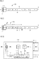
- FIG 1 shows an exemplary structure of an ASD aspirating smoke detector in smoke-free normal operation.
- An intake/detector unit ADE can be seen on the left as a structural unit, to which an intake pipe R with a large number of intake openings OF arranged in a distributed manner is connected.
- the latter are usually holes that are introduced into the intake manifold R.
- the suction openings OF typically have a non-uniform cross-section in order to achieve essentially the same "hole sensitivity" for all suction openings OF. That is to say, in normal operation, each of the intake openings OF sucks in approximately the same intake volume per unit of time.
- a calibration hole present at a right-hand end of the pipe is denoted by K.
- the intake/detector unit ADE shown comprises an intake unit L in the form of a fan, such as a radial fan, and a fire detector unit DET upstream in the direction of flow.
- v M is denotes the mean flow velocity.
- the air flow or air volume flow sucked in by the suction unit L corresponds to the volume per time from the product of the mean flow velocity v M and the cross-section of the inside of the suction pipe R.
- FIG 2 shows the example according to FIG 1 in the event of a detected fire.
- Room air with smoke to be detected is sucked in at an intake opening OF, symbolized by a flame symbol, and transported through the intake pipe R to the fire detector unit DET.
- the lightning bolt on the DET fire detector unit symbolizes a detected fire event. This is the case when a detection signal DL output by the fire detector unit DET exceeds a predetermined minimum detection level MIN.
- T An associated transport time is denoted by T.
- the transport time T results from the product of the mean flow velocity v M and the transport distance ST shown. As described above, the transport time T can be up to several minutes.
- FIG. 3 shows an example of an aspirating smoke detector ASD according to the invention.
- the functional structure of the aspiration/detector unit ADE is shown in detail.
- a pipe connection AN to which the suction pipe R is connected can be seen in the right-hand part of the suction/detector unit ADE realized as a structural unit.
- the aspiration/detector unit ADE itself includes the fire detector unit DET for the metrological determination of the signal level DL of a fire parameter. The latter is a smoke concentration level in the present example.
- the aspirating smoke detector ASD or the aspirating/detector unit ADE also includes a power control unit DR, which is set up for setting an aspirating power P of the aspirating unit L.
- the intake unit L is a fan, the intake power P of which changes the fan speed n L can be adjusted.
- the aspirating smoke detector ASD or the aspirating/detector unit ADE has an air flow meter SEN for detecting an air flow V ⁇ , ⁇ of the aspirated room air.
- the air flow is an air volume flow V ⁇ or an air mass flow ⁇ .
- the air flow meter SEN outputs a corresponding air flow measurement signal, which represents the air volume flow V ⁇ or the air mass flow ⁇ .
- the aspirating smoke detector ASD or the aspirating/detector unit ADE has an electronic control unit MC connected to the fire detector unit DET, to the air flow meter SEN and to the power control unit DR.
- the latter is typically a microcontroller and is set up or programmed to set the intake power P of the intake unit L to a nominal air flow value NW for (smoke-free) normal operation using the power control unit DR.
- the intake power P can be set in the form of an open or closed control loop, based on a currently recorded air volume flow V ⁇ or air mass flow ⁇ in comparison with the nominal air flow value NW stored in an electronic memory MEM of the control unit MC.
- the control unit MC is also set up to issue a fire alarm AL when a fire is detected and set up to issue an interruption message U in normal operation if the detected air flow V ⁇ , ⁇ exceeds a predetermined upper limit value V ⁇ +, ⁇ + for a minimum period of time ZR.
- the fire alarm AL and, if applicable, the interruption message U and a blockage message V can be output by means of the electronic control unit MC, for example at a bus interface of the suction/detector unit ADE.
- the control unit MC is also set up or programmed to increase the intake power P by means of the power control unit DR from a minimum signal level value MIN of the signal level DL, ie when the minimum signal level value is exceeded SIG, to shorten the transport time T of aspirated room air with smoke and/or with fire gas through the intake pipe R to the fire detector unit DET.
- control unit MC is set up or programmed according to the invention to increase the intake power P by means of the power control unit DR from the detected minimum signal level value MIN only in such a way that the set air flow V ⁇ , ⁇ does not exceed the upper limit value V ⁇ +, ⁇ +.
- Both the minimum signal level value MIN and the upper limit value V ⁇ +, ⁇ + for the air volume flow V ⁇ or for the air mass flow ⁇ can be stored in the electronic memory MEM for a mathematical comparison by the control unit MC.
- the electronic control unit MC can be set up to increase the intake power P from the minimum signal level value MIN only for a period of time less than the minimum period ZR, in which the air flow V ⁇ , ⁇ exceeds the upper limit value V ⁇ +, ⁇ +.
- the electronic control unit MC can be set up or programmed to reduce the intake power P by means of the power control unit DR (shortly) before the end of the minimum period ZR is reached in such a way that the air flow V ⁇ , ⁇ exceeds the upper limit value V ⁇ +, ⁇ + falls below again.
- the electronic control unit MC can be set up to output a blockage message V if the detected air flow V ⁇ , ⁇ falls below a predefined lower limit value V ⁇ -, ⁇ - for a predefined minimum period ZR.
- This lower limit value V ⁇ -, ⁇ - can also be stored in the electronic memory MEM for a mathematical comparison by the control unit MC.
- a computer program product PRG as well as the minimum signal level value MIN and the nominal air flow value NW as Operating parameters PAR and, if applicable, the upper and lower limit values V ⁇ +, ⁇ + ; V ⁇ -, ⁇ - for the air flow V ⁇ , ⁇ and/or the minimum period of time ZR can be stored as further operating parameters PAR in the electronic memory MEM of the electronic control unit MC, preferably in a non-volatile manner.
- the computer program product PRG is set up on an electronic control unit MC, preferably on a processor-supported microcontroller, of the aspirating smoke detector ASD to carry out the operating method according to the invention. It includes corresponding suitable program steps and program routines for operating, ie for controlling and monitoring, the aspirating smoke detector ASD.
Landscapes
- Physics & Mathematics (AREA)
- General Physics & Mathematics (AREA)
- Engineering & Computer Science (AREA)
- Emergency Management (AREA)
- Business, Economics & Management (AREA)
- Chemical & Material Sciences (AREA)
- Analytical Chemistry (AREA)
- Computer Security & Cryptography (AREA)
- Health & Medical Sciences (AREA)
- Life Sciences & Earth Sciences (AREA)
- Automation & Control Theory (AREA)
- Molecular Biology (AREA)
- Biochemistry (AREA)
- General Health & Medical Sciences (AREA)
- Immunology (AREA)
- Pathology (AREA)
- Biomedical Technology (AREA)
- General Engineering & Computer Science (AREA)
- Computer Networks & Wireless Communication (AREA)
- Fire-Detection Mechanisms (AREA)
- Fire Alarms (AREA)
Priority Applications (3)
| Application Number | Priority Date | Filing Date | Title |
|---|---|---|---|
| CA3159017A CA3159017C (fr) | 2021-05-18 | 2022-05-16 | Accroissement de la puissance d'aspiration d'un detecteur de fumee aspirant pour reduire le temps de transport d'une valeur de niveau de signal minimale detectee sans la sortie d'un signal interrompu |
| US17/745,241 US11704987B2 (en) | 2021-05-18 | 2022-05-16 | Increasing the suction power in an aspirating smoke detector (ASD) to shorten the transport time from a detected minimum signal level value without the output of an interruption signal |
| CN202210537451.3A CN115376262B (zh) | 2021-05-18 | 2022-05-18 | 抽取式烟雾检测器及其操作方法和计算机程序产品 |
Applications Claiming Priority (1)
| Application Number | Priority Date | Filing Date | Title |
|---|---|---|---|
| EP21174278 | 2021-05-18 |
Publications (2)
| Publication Number | Publication Date |
|---|---|
| EP4092645A1 true EP4092645A1 (fr) | 2022-11-23 |
| EP4092645B1 EP4092645B1 (fr) | 2025-01-08 |
Family
ID=75977628
Family Applications (1)
| Application Number | Title | Priority Date | Filing Date |
|---|---|---|---|
| EP22159123.3A Active EP4092645B1 (fr) | 2021-05-18 | 2022-02-28 | Augmentation de la puissance d'aspiration pour un détecteur de fumée par aspiration (asd) permettant de réduire le temps de transport à une valeur de niveau de signal minimum détecté sans émettre de message d'interruption |
Country Status (5)
| Country | Link |
|---|---|
| US (1) | US11704987B2 (fr) |
| EP (1) | EP4092645B1 (fr) |
| CN (1) | CN115376262B (fr) |
| CA (1) | CA3159017C (fr) |
| DE (1) | DE202022003140U1 (fr) |
Cited By (2)
| Publication number | Priority date | Publication date | Assignee | Title |
|---|---|---|---|---|
| CN118258101A (zh) * | 2024-05-10 | 2024-06-28 | 北京泰豪智能工程有限公司 | 一种大型公共建筑的能源诊断方法 |
| WO2024193894A1 (fr) * | 2023-03-20 | 2024-09-26 | Siemens Schweiz Ag | Vérification d'un dispositif de surveillance de flux d'air d'un détecteur de fumée par aspiration dans un mode de test par augmentation et abaissement de la vitesse de rotation de ventilateur du détecteur de fumée par aspiration |
Families Citing this family (1)
| Publication number | Priority date | Publication date | Assignee | Title |
|---|---|---|---|---|
| US12198531B2 (en) * | 2022-01-19 | 2025-01-14 | Tyco Fire & Security Gmbh | Smoke detector self-test |
Citations (4)
| Publication number | Priority date | Publication date | Assignee | Title |
|---|---|---|---|---|
| EP1006500A2 (fr) * | 1998-12-04 | 2000-06-07 | Pittway Corporation | Détecteur de fumée avec unité d'aspiration et capteur de débit |
| EP1638062A1 (fr) * | 2004-09-09 | 2006-03-22 | HEKATRON Technik GmbH | Détecteur de fumée à aspiration et méthode de son fonctionnement |
| EP2244236A1 (fr) | 2009-04-23 | 2010-10-27 | Honeywell International Inc. | Détecteur de fumée aspirant à vitesse d'air variable |
| EP2407946A1 (fr) | 2010-07-15 | 2012-01-18 | Siemens Schweiz AG | Détection d'encrassements et de ruptures dans un détecteur de fumées par aspiration (ASD) |
Family Cites Families (6)
| Publication number | Priority date | Publication date | Assignee | Title |
|---|---|---|---|---|
| US5945924A (en) * | 1996-01-29 | 1999-08-31 | Marman; Douglas H. | Fire and smoke detection and control system |
| EP2309468A1 (fr) * | 2009-10-09 | 2011-04-13 | Amrona AG | Procédé, dispositif et produit de programme informatique pour la projection d'un système de détection d'incendie du type aspirateur |
| HK1213630A1 (zh) | 2012-10-16 | 2016-07-08 | 爱克斯崔里斯科技有限公司 | 微粒探测寻址技术 |
| EP3091517B1 (fr) * | 2015-05-06 | 2017-06-28 | Siemens Schweiz AG | Détecteur de fumée à écran diffusant ouvert et appareil de contrôle pour un tel détecteur de fumée à écran diffusant ouvert |
| US12096916B2 (en) * | 2017-12-28 | 2024-09-24 | Cilag Gmbh International | Method of sensing particulate from smoke evacuated from a patient, adjusting the pump speed based on the sensed information, and communicating the functional parameters of the system to the hub |
| JP7269026B2 (ja) * | 2018-09-28 | 2023-05-08 | ホーチキ株式会社 | 可搬式の煙検知装置、固定式の煙検知装置及び煙発生位置の特定方法 |
-
2022
- 2022-02-28 EP EP22159123.3A patent/EP4092645B1/fr active Active
- 2022-02-28 DE DE202022003140.8U patent/DE202022003140U1/de active Active
- 2022-05-16 CA CA3159017A patent/CA3159017C/fr active Active
- 2022-05-16 US US17/745,241 patent/US11704987B2/en active Active
- 2022-05-18 CN CN202210537451.3A patent/CN115376262B/zh active Active
Patent Citations (4)
| Publication number | Priority date | Publication date | Assignee | Title |
|---|---|---|---|---|
| EP1006500A2 (fr) * | 1998-12-04 | 2000-06-07 | Pittway Corporation | Détecteur de fumée avec unité d'aspiration et capteur de débit |
| EP1638062A1 (fr) * | 2004-09-09 | 2006-03-22 | HEKATRON Technik GmbH | Détecteur de fumée à aspiration et méthode de son fonctionnement |
| EP2244236A1 (fr) | 2009-04-23 | 2010-10-27 | Honeywell International Inc. | Détecteur de fumée aspirant à vitesse d'air variable |
| EP2407946A1 (fr) | 2010-07-15 | 2012-01-18 | Siemens Schweiz AG | Détection d'encrassements et de ruptures dans un détecteur de fumées par aspiration (ASD) |
Cited By (2)
| Publication number | Priority date | Publication date | Assignee | Title |
|---|---|---|---|---|
| WO2024193894A1 (fr) * | 2023-03-20 | 2024-09-26 | Siemens Schweiz Ag | Vérification d'un dispositif de surveillance de flux d'air d'un détecteur de fumée par aspiration dans un mode de test par augmentation et abaissement de la vitesse de rotation de ventilateur du détecteur de fumée par aspiration |
| CN118258101A (zh) * | 2024-05-10 | 2024-06-28 | 北京泰豪智能工程有限公司 | 一种大型公共建筑的能源诊断方法 |
Also Published As
| Publication number | Publication date |
|---|---|
| US20220383721A1 (en) | 2022-12-01 |
| CN115376262A (zh) | 2022-11-22 |
| CA3159017A1 (fr) | 2022-11-18 |
| DE202022003140U1 (de) | 2025-01-20 |
| CA3159017C (fr) | 2024-01-30 |
| US11704987B2 (en) | 2023-07-18 |
| EP4092645B1 (fr) | 2025-01-08 |
| CN115376262B (zh) | 2025-04-04 |
Similar Documents
| Publication | Publication Date | Title |
|---|---|---|
| EP4092645B1 (fr) | Augmentation de la puissance d'aspiration pour un détecteur de fumée par aspiration (asd) permettant de réduire le temps de transport à une valeur de niveau de signal minimum détecté sans émettre de message d'interruption | |
| EP2500882B1 (fr) | Système d'alarme incendie et de gaz inflammable et procédé associé | |
| EP2407946B1 (fr) | Détection d'encrassements et de ruptures dans un détecteur de fumées par aspiration (ASD) | |
| DE102004021663A1 (de) | Umgebungsbedingungsdetektor mit mehreren Sensoren und einer einzelnen Steuereinheit | |
| EP2270762B1 (fr) | Détecteur de fumée et procédé de contrôle des impuretés sur les ouvertures de passage des fumées | |
| DE69221756T2 (de) | Leckermittlungssystem | |
| EP1634261A1 (fr) | Procede et dispositif pour reconnaitre et localiser un incendie | |
| DE69315463T2 (de) | Subsonische Venturi-proportionale und isokinetische Probenentnahmeverfahren und Vorrichtung | |
| DE102004036989A1 (de) | Detektor mit Staubfilter und Luftstromüberwachungseinheit | |
| EP2848913A1 (fr) | Appareil de détection pour la détermination de particules fines | |
| EP3220141A1 (fr) | Procédé de vérification d'un capteur de gaz et dispositif de mesure de gaz, détecteur de gaz comprenant un dispositif de vérification d'un capteur de gaz | |
| EP3465647A1 (fr) | Procédé et avertisseur de danger pour la détection de fumée | |
| EP3392855B1 (fr) | Procédé et dispositif destinés à aligner un détecteur de fumée | |
| CH681827A5 (fr) | ||
| EP4264590A1 (fr) | Cellule électrochimique et procédé de fabrication d'une cellule électrochimique | |
| EP1224641A1 (fr) | Dispositif de detection de fumee | |
| EP3612279B1 (fr) | Installation d'extinction d'incendie, système d'extinction d'incendie comportant cette dernière, ainsi que procédé pour la détermination de la propagation d'un feu | |
| DE69313739T2 (de) | Rauchdetektierungsvorrichtung für Feueralarm | |
| DD297706A5 (de) | Verfahren zur ueberpruefung des bestehens einer rohrleitungsverbindung zwischen zwei endpunkten | |
| DE102006045055B3 (de) | Gasmeldeeinrichtung und Verfahren zum Überprüfen einer solchen | |
| EP0344618B1 (fr) | Dispositif de prélèvement d'échantillon de gaz | |
| EP1360669B1 (fr) | Procede et dispositif pour surveiller des installations souterraines | |
| EP2297717A1 (fr) | Détermination du délai de réponse d'un avertisseur de danger | |
| WO2024193894A1 (fr) | Vérification d'un dispositif de surveillance de flux d'air d'un détecteur de fumée par aspiration dans un mode de test par augmentation et abaissement de la vitesse de rotation de ventilateur du détecteur de fumée par aspiration | |
| DE102015015151B4 (de) | Gasmesssystem mit einer Gasmessvorichtung und einer Pumpeneinrichtung und Verfahren zum Betrieb einer Gasmessvorrichtung mittels einer Pumpeinrichtung |
Legal Events
| Date | Code | Title | Description |
|---|---|---|---|
| REG | Reference to a national code |
Ref country code: DE Ref legal event code: R138 Ref document number: 202022003140 Country of ref document: DE Free format text: GERMAN DOCUMENT NUMBER IS 502022002605 |
|
| PUAI | Public reference made under article 153(3) epc to a published international application that has entered the european phase |
Free format text: ORIGINAL CODE: 0009012 |
|
| STAA | Information on the status of an ep patent application or granted ep patent |
Free format text: STATUS: THE APPLICATION HAS BEEN PUBLISHED |
|
| AK | Designated contracting states |
Kind code of ref document: A1 Designated state(s): AL AT BE BG CH CY CZ DE DK EE ES FI FR GB GR HR HU IE IS IT LI LT LU LV MC MK MT NL NO PL PT RO RS SE SI SK SM TR |
|
| STAA | Information on the status of an ep patent application or granted ep patent |
Free format text: STATUS: REQUEST FOR EXAMINATION WAS MADE |
|
| 17P | Request for examination filed |
Effective date: 20230523 |
|
| RBV | Designated contracting states (corrected) |
Designated state(s): AL AT BE BG CH CY CZ DE DK EE ES FI FR GB GR HR HU IE IS IT LI LT LU LV MC MK MT NL NO PL PT RO RS SE SI SK SM TR |
|
| STAA | Information on the status of an ep patent application or granted ep patent |
Free format text: STATUS: EXAMINATION IS IN PROGRESS |
|
| 17Q | First examination report despatched |
Effective date: 20231012 |
|
| GRAP | Despatch of communication of intention to grant a patent |
Free format text: ORIGINAL CODE: EPIDOSNIGR1 |
|
| STAA | Information on the status of an ep patent application or granted ep patent |
Free format text: STATUS: GRANT OF PATENT IS INTENDED |
|
| INTG | Intention to grant announced |
Effective date: 20240913 |
|
| GRAS | Grant fee paid |
Free format text: ORIGINAL CODE: EPIDOSNIGR3 |
|
| GRAA | (expected) grant |
Free format text: ORIGINAL CODE: 0009210 |
|
| STAA | Information on the status of an ep patent application or granted ep patent |
Free format text: STATUS: THE PATENT HAS BEEN GRANTED |
|
| AK | Designated contracting states |
Kind code of ref document: B1 Designated state(s): AL AT BE BG CH CY CZ DE DK EE ES FI FR GB GR HR HU IE IS IT LI LT LU LV MC MK MT NL NO PL PT RO RS SE SI SK SM TR |
|
| REG | Reference to a national code |
Ref country code: GB Ref legal event code: FG4D Free format text: NOT ENGLISH |
|
| REG | Reference to a national code |
Ref country code: CH Ref legal event code: EP |
|
| REG | Reference to a national code |
Ref country code: DE Ref legal event code: R096 Ref document number: 502022002605 Country of ref document: DE |
|
| REG | Reference to a national code |
Ref country code: IE Ref legal event code: FG4D Free format text: LANGUAGE OF EP DOCUMENT: GERMAN |
|
| REG | Reference to a national code |
Ref country code: NL Ref legal event code: FP |
|
| REG | Reference to a national code |
Ref country code: LT Ref legal event code: MG9D |
|
| P01 | Opt-out of the competence of the unified patent court (upc) registered |
Free format text: CASE NUMBER: APP_17831/2025 Effective date: 20250411 |
|
| PG25 | Lapsed in a contracting state [announced via postgrant information from national office to epo] |
Ref country code: RS Free format text: LAPSE BECAUSE OF FAILURE TO SUBMIT A TRANSLATION OF THE DESCRIPTION OR TO PAY THE FEE WITHIN THE PRESCRIBED TIME-LIMIT Effective date: 20250408 |
|
| PG25 | Lapsed in a contracting state [announced via postgrant information from national office to epo] |
Ref country code: PL Free format text: LAPSE BECAUSE OF FAILURE TO SUBMIT A TRANSLATION OF THE DESCRIPTION OR TO PAY THE FEE WITHIN THE PRESCRIBED TIME-LIMIT Effective date: 20250108 |
|
| PGFP | Annual fee paid to national office [announced via postgrant information from national office to epo] |
Ref country code: DE Payment date: 20250417 Year of fee payment: 4 |
|
| PG25 | Lapsed in a contracting state [announced via postgrant information from national office to epo] |
Ref country code: ES Free format text: LAPSE BECAUSE OF FAILURE TO SUBMIT A TRANSLATION OF THE DESCRIPTION OR TO PAY THE FEE WITHIN THE PRESCRIBED TIME-LIMIT Effective date: 20250108 |
|
| PG25 | Lapsed in a contracting state [announced via postgrant information from national office to epo] |
Ref country code: NO Free format text: LAPSE BECAUSE OF FAILURE TO SUBMIT A TRANSLATION OF THE DESCRIPTION OR TO PAY THE FEE WITHIN THE PRESCRIBED TIME-LIMIT Effective date: 20250408 Ref country code: IS Free format text: LAPSE BECAUSE OF FAILURE TO SUBMIT A TRANSLATION OF THE DESCRIPTION OR TO PAY THE FEE WITHIN THE PRESCRIBED TIME-LIMIT Effective date: 20250508 |
|
| PG25 | Lapsed in a contracting state [announced via postgrant information from national office to epo] |
Ref country code: HR Free format text: LAPSE BECAUSE OF FAILURE TO SUBMIT A TRANSLATION OF THE DESCRIPTION OR TO PAY THE FEE WITHIN THE PRESCRIBED TIME-LIMIT Effective date: 20250108 |
|
| PG25 | Lapsed in a contracting state [announced via postgrant information from national office to epo] |
Ref country code: LV Free format text: LAPSE BECAUSE OF FAILURE TO SUBMIT A TRANSLATION OF THE DESCRIPTION OR TO PAY THE FEE WITHIN THE PRESCRIBED TIME-LIMIT Effective date: 20250108 Ref country code: PT Free format text: LAPSE BECAUSE OF FAILURE TO SUBMIT A TRANSLATION OF THE DESCRIPTION OR TO PAY THE FEE WITHIN THE PRESCRIBED TIME-LIMIT Effective date: 20250508 |
|
| PG25 | Lapsed in a contracting state [announced via postgrant information from national office to epo] |
Ref country code: GR Free format text: LAPSE BECAUSE OF FAILURE TO SUBMIT A TRANSLATION OF THE DESCRIPTION OR TO PAY THE FEE WITHIN THE PRESCRIBED TIME-LIMIT Effective date: 20250409 Ref country code: BG Free format text: LAPSE BECAUSE OF FAILURE TO SUBMIT A TRANSLATION OF THE DESCRIPTION OR TO PAY THE FEE WITHIN THE PRESCRIBED TIME-LIMIT Effective date: 20250108 |
|
| PGFP | Annual fee paid to national office [announced via postgrant information from national office to epo] |
Ref country code: CH Payment date: 20250512 Year of fee payment: 4 |
|
| PG25 | Lapsed in a contracting state [announced via postgrant information from national office to epo] |
Ref country code: SE Free format text: LAPSE BECAUSE OF FAILURE TO SUBMIT A TRANSLATION OF THE DESCRIPTION OR TO PAY THE FEE WITHIN THE PRESCRIBED TIME-LIMIT Effective date: 20250108 |
|
| PG25 | Lapsed in a contracting state [announced via postgrant information from national office to epo] |
Ref country code: SM Free format text: LAPSE BECAUSE OF FAILURE TO SUBMIT A TRANSLATION OF THE DESCRIPTION OR TO PAY THE FEE WITHIN THE PRESCRIBED TIME-LIMIT Effective date: 20250108 |
|
| REG | Reference to a national code |
Ref country code: DE Ref legal event code: R097 Ref document number: 502022002605 Country of ref document: DE |
|
| PG25 | Lapsed in a contracting state [announced via postgrant information from national office to epo] |
Ref country code: DK Free format text: LAPSE BECAUSE OF FAILURE TO SUBMIT A TRANSLATION OF THE DESCRIPTION OR TO PAY THE FEE WITHIN THE PRESCRIBED TIME-LIMIT Effective date: 20250108 |
|
| PG25 | Lapsed in a contracting state [announced via postgrant information from national office to epo] |
Ref country code: MC Free format text: LAPSE BECAUSE OF FAILURE TO SUBMIT A TRANSLATION OF THE DESCRIPTION OR TO PAY THE FEE WITHIN THE PRESCRIBED TIME-LIMIT Effective date: 20250108 |
|
| PG25 | Lapsed in a contracting state [announced via postgrant information from national office to epo] |
Ref country code: LU Free format text: LAPSE BECAUSE OF NON-PAYMENT OF DUE FEES Effective date: 20250228 |
|
| PG25 | Lapsed in a contracting state [announced via postgrant information from national office to epo] |
Ref country code: EE Free format text: LAPSE BECAUSE OF FAILURE TO SUBMIT A TRANSLATION OF THE DESCRIPTION OR TO PAY THE FEE WITHIN THE PRESCRIBED TIME-LIMIT Effective date: 20250108 Ref country code: CZ Free format text: LAPSE BECAUSE OF FAILURE TO SUBMIT A TRANSLATION OF THE DESCRIPTION OR TO PAY THE FEE WITHIN THE PRESCRIBED TIME-LIMIT Effective date: 20250108 |
|
| PG25 | Lapsed in a contracting state [announced via postgrant information from national office to epo] |
Ref country code: RO Free format text: LAPSE BECAUSE OF FAILURE TO SUBMIT A TRANSLATION OF THE DESCRIPTION OR TO PAY THE FEE WITHIN THE PRESCRIBED TIME-LIMIT Effective date: 20250108 |
|
| PG25 | Lapsed in a contracting state [announced via postgrant information from national office to epo] |
Ref country code: SK Free format text: LAPSE BECAUSE OF FAILURE TO SUBMIT A TRANSLATION OF THE DESCRIPTION OR TO PAY THE FEE WITHIN THE PRESCRIBED TIME-LIMIT Effective date: 20250108 |
|
| PLBE | No opposition filed within time limit |
Free format text: ORIGINAL CODE: 0009261 |
|
| STAA | Information on the status of an ep patent application or granted ep patent |
Free format text: STATUS: NO OPPOSITION FILED WITHIN TIME LIMIT |
|
| REG | Reference to a national code |
Ref country code: BE Ref legal event code: MM Effective date: 20250228 |
|
| 26N | No opposition filed |
Effective date: 20251009 |
|
| PG25 | Lapsed in a contracting state [announced via postgrant information from national office to epo] |
Ref country code: BE Free format text: LAPSE BECAUSE OF NON-PAYMENT OF DUE FEES Effective date: 20250228 |
|
| PG25 | Lapsed in a contracting state [announced via postgrant information from national office to epo] |
Ref country code: IE Free format text: LAPSE BECAUSE OF NON-PAYMENT OF DUE FEES Effective date: 20250228 |
|
| PGFP | Annual fee paid to national office [announced via postgrant information from national office to epo] |
Ref country code: NL Payment date: 20260209 Year of fee payment: 5 |
|
| PGFP | Annual fee paid to national office [announced via postgrant information from national office to epo] |
Ref country code: GB Payment date: 20260310 Year of fee payment: 5 |
|
| PGFP | Annual fee paid to national office [announced via postgrant information from national office to epo] |
Ref country code: AT Payment date: 20260301 Year of fee payment: 5 |
|
| PGFP | Annual fee paid to national office [announced via postgrant information from national office to epo] |
Ref country code: IT Payment date: 20260225 Year of fee payment: 5 |
|
| PGFP | Annual fee paid to national office [announced via postgrant information from national office to epo] |
Ref country code: FR Payment date: 20260213 Year of fee payment: 5 |