EP4092837B1 - Douille de lampe d'appareils de cuisson à liaison de contact non rivée - Google Patents
Douille de lampe d'appareils de cuisson à liaison de contact non rivée Download PDFInfo
- Publication number
- EP4092837B1 EP4092837B1 EP22158398.2A EP22158398A EP4092837B1 EP 4092837 B1 EP4092837 B1 EP 4092837B1 EP 22158398 A EP22158398 A EP 22158398A EP 4092837 B1 EP4092837 B1 EP 4092837B1
- Authority
- EP
- European Patent Office
- Prior art keywords
- contact
- holder
- cooking device
- socket
- supply
- Prior art date
- Legal status (The legal status is an assumption and is not a legal conclusion. Google has not performed a legal analysis and makes no representation as to the accuracy of the status listed.)
- Active
Links
Images



Classifications
-
- H—ELECTRICITY
- H01—ELECTRIC ELEMENTS
- H01R—ELECTRICALLY-CONDUCTIVE CONNECTIONS; STRUCTURAL ASSOCIATIONS OF A PLURALITY OF MUTUALLY-INSULATED ELECTRICAL CONNECTING ELEMENTS; COUPLING DEVICES; CURRENT COLLECTORS
- H01R33/00—Coupling devices specially adapted for supporting apparatus and having one part acting as a holder providing support and electrical connection via a counterpart which is structurally associated with the apparatus, e.g. lamp holders; Separate parts thereof
- H01R33/97—Holders with separate means to prevent loosening of the coupling or unauthorised removal of apparatus held
-
- H—ELECTRICITY
- H01—ELECTRIC ELEMENTS
- H01R—ELECTRICALLY-CONDUCTIVE CONNECTIONS; STRUCTURAL ASSOCIATIONS OF A PLURALITY OF MUTUALLY-INSULATED ELECTRICAL CONNECTING ELEMENTS; COUPLING DEVICES; CURRENT COLLECTORS
- H01R33/00—Coupling devices specially adapted for supporting apparatus and having one part acting as a holder providing support and electrical connection via a counterpart which is structurally associated with the apparatus, e.g. lamp holders; Separate parts thereof
- H01R33/05—Two-pole devices
- H01R33/06—Two-pole devices with two current-carrying pins, blades or analogous contacts, having their axes parallel to each other
- H01R33/09—Two-pole devices with two current-carrying pins, blades or analogous contacts, having their axes parallel to each other for baseless lamp bulb
-
- H—ELECTRICITY
- H01—ELECTRIC ELEMENTS
- H01R—ELECTRICALLY-CONDUCTIVE CONNECTIONS; STRUCTURAL ASSOCIATIONS OF A PLURALITY OF MUTUALLY-INSULATED ELECTRICAL CONNECTING ELEMENTS; COUPLING DEVICES; CURRENT COLLECTORS
- H01R13/00—Details of coupling devices of the kinds covered by groups H01R12/70 or H01R24/00 - H01R33/00
- H01R13/02—Contact members
- H01R13/04—Pins or blades for co-operation with sockets
- H01R13/08—Resiliently-mounted rigid pins or blades
-
- H—ELECTRICITY
- H01—ELECTRIC ELEMENTS
- H01R—ELECTRICALLY-CONDUCTIVE CONNECTIONS; STRUCTURAL ASSOCIATIONS OF A PLURALITY OF MUTUALLY-INSULATED ELECTRICAL CONNECTING ELEMENTS; COUPLING DEVICES; CURRENT COLLECTORS
- H01R13/00—Details of coupling devices of the kinds covered by groups H01R12/70 or H01R24/00 - H01R33/00
- H01R13/02—Contact members
- H01R13/10—Sockets for co-operation with pins or blades
- H01R13/11—Resilient sockets
- H01R13/112—Resilient sockets forked sockets having two legs
-
- H—ELECTRICITY
- H01—ELECTRIC ELEMENTS
- H01R—ELECTRICALLY-CONDUCTIVE CONNECTIONS; STRUCTURAL ASSOCIATIONS OF A PLURALITY OF MUTUALLY-INSULATED ELECTRICAL CONNECTING ELEMENTS; COUPLING DEVICES; CURRENT COLLECTORS
- H01R13/00—Details of coupling devices of the kinds covered by groups H01R12/70 or H01R24/00 - H01R33/00
- H01R13/40—Securing contact members in or to a base or case; Insulating of contact members
-
- H—ELECTRICITY
- H01—ELECTRIC ELEMENTS
- H01R—ELECTRICALLY-CONDUCTIVE CONNECTIONS; STRUCTURAL ASSOCIATIONS OF A PLURALITY OF MUTUALLY-INSULATED ELECTRICAL CONNECTING ELEMENTS; COUPLING DEVICES; CURRENT COLLECTORS
- H01R13/00—Details of coupling devices of the kinds covered by groups H01R12/70 or H01R24/00 - H01R33/00
- H01R13/40—Securing contact members in or to a base or case; Insulating of contact members
- H01R13/42—Securing in a demountable manner
- H01R13/428—Securing in a demountable manner by resilient locking means on the contact members; by locking means on resilient contact members
- H01R13/432—Securing in a demountable manner by resilient locking means on the contact members; by locking means on resilient contact members by stamped-out resilient tongue snapping behind shoulder in base or case
-
- H—ELECTRICITY
- H01—ELECTRIC ELEMENTS
- H01R—ELECTRICALLY-CONDUCTIVE CONNECTIONS; STRUCTURAL ASSOCIATIONS OF A PLURALITY OF MUTUALLY-INSULATED ELECTRICAL CONNECTING ELEMENTS; COUPLING DEVICES; CURRENT COLLECTORS
- H01R33/00—Coupling devices specially adapted for supporting apparatus and having one part acting as a holder providing support and electrical connection via a counterpart which is structurally associated with the apparatus, e.g. lamp holders; Separate parts thereof
- H01R33/02—Single-pole devices, e.g. holder for supporting one end of a tubular incandescent or neon lamp
-
- H—ELECTRICITY
- H01—ELECTRIC ELEMENTS
- H01R—ELECTRICALLY-CONDUCTIVE CONNECTIONS; STRUCTURAL ASSOCIATIONS OF A PLURALITY OF MUTUALLY-INSULATED ELECTRICAL CONNECTING ELEMENTS; COUPLING DEVICES; CURRENT COLLECTORS
- H01R33/00—Coupling devices specially adapted for supporting apparatus and having one part acting as a holder providing support and electrical connection via a counterpart which is structurally associated with the apparatus, e.g. lamp holders; Separate parts thereof
- H01R33/05—Two-pole devices
- H01R33/06—Two-pole devices with two current-carrying pins, blades or analogous contacts, having their axes parallel to each other
-
- H—ELECTRICITY
- H01—ELECTRIC ELEMENTS
- H01R—ELECTRICALLY-CONDUCTIVE CONNECTIONS; STRUCTURAL ASSOCIATIONS OF A PLURALITY OF MUTUALLY-INSULATED ELECTRICAL CONNECTING ELEMENTS; COUPLING DEVICES; CURRENT COLLECTORS
- H01R33/00—Coupling devices specially adapted for supporting apparatus and having one part acting as a holder providing support and electrical connection via a counterpart which is structurally associated with the apparatus, e.g. lamp holders; Separate parts thereof
- H01R33/94—Holders formed as intermediate parts for linking a counter-part to a coupling part
-
- H—ELECTRICITY
- H01—ELECTRIC ELEMENTS
- H01R—ELECTRICALLY-CONDUCTIVE CONNECTIONS; STRUCTURAL ASSOCIATIONS OF A PLURALITY OF MUTUALLY-INSULATED ELECTRICAL CONNECTING ELEMENTS; COUPLING DEVICES; CURRENT COLLECTORS
- H01R4/00—Electrically-conductive connections between two or more conductive members in direct contact, i.e. touching one another; Means for effecting or maintaining such contact; Electrically-conductive connections having two or more spaced connecting locations for conductors and using contact members penetrating insulation
- H01R4/28—Clamped connections, spring connections
- H01R4/48—Clamped connections, spring connections utilising a spring, clip, or other resilient member
- H01R4/4809—Clamped connections, spring connections utilising a spring, clip, or other resilient member using a leaf spring to bias the conductor toward the busbar
- H01R4/4828—Spring-activating arrangements mounted on or integrally formed with the spring housing
- H01R4/483—Pivoting arrangements, e.g. lever pushing on the spring
-
- H—ELECTRICITY
- H01—ELECTRIC ELEMENTS
- H01R—ELECTRICALLY-CONDUCTIVE CONNECTIONS; STRUCTURAL ASSOCIATIONS OF A PLURALITY OF MUTUALLY-INSULATED ELECTRICAL CONNECTING ELEMENTS; COUPLING DEVICES; CURRENT COLLECTORS
- H01R13/00—Details of coupling devices of the kinds covered by groups H01R12/70 or H01R24/00 - H01R33/00
- H01R13/40—Securing contact members in or to a base or case; Insulating of contact members
- H01R13/42—Securing in a demountable manner
- H01R13/428—Securing in a demountable manner by resilient locking means on the contact members; by locking means on resilient contact members
-
- H—ELECTRICITY
- H01—ELECTRIC ELEMENTS
- H01R—ELECTRICALLY-CONDUCTIVE CONNECTIONS; STRUCTURAL ASSOCIATIONS OF A PLURALITY OF MUTUALLY-INSULATED ELECTRICAL CONNECTING ELEMENTS; COUPLING DEVICES; CURRENT COLLECTORS
- H01R4/00—Electrically-conductive connections between two or more conductive members in direct contact, i.e. touching one another; Means for effecting or maintaining such contact; Electrically-conductive connections having two or more spaced connecting locations for conductors and using contact members penetrating insulation
- H01R4/28—Clamped connections, spring connections
- H01R4/48—Clamped connections, spring connections utilising a spring, clip, or other resilient member
- H01R4/4809—Clamped connections, spring connections utilising a spring, clip, or other resilient member using a leaf spring to bias the conductor toward the busbar
- H01R4/48185—Clamped connections, spring connections utilising a spring, clip, or other resilient member using a leaf spring to bias the conductor toward the busbar adapted for axial insertion of a wire end
- H01R4/4819—Clamped connections, spring connections utilising a spring, clip, or other resilient member using a leaf spring to bias the conductor toward the busbar adapted for axial insertion of a wire end the spring shape allowing insertion of the conductor end when the spring is unbiased
- H01R4/4821—Single-blade spring
-
- H—ELECTRICITY
- H01—ELECTRIC ELEMENTS
- H01R—ELECTRICALLY-CONDUCTIVE CONNECTIONS; STRUCTURAL ASSOCIATIONS OF A PLURALITY OF MUTUALLY-INSULATED ELECTRICAL CONNECTING ELEMENTS; COUPLING DEVICES; CURRENT COLLECTORS
- H01R4/00—Electrically-conductive connections between two or more conductive members in direct contact, i.e. touching one another; Means for effecting or maintaining such contact; Electrically-conductive connections having two or more spaced connecting locations for conductors and using contact members penetrating insulation
- H01R4/28—Clamped connections, spring connections
- H01R4/48—Clamped connections, spring connections utilising a spring, clip, or other resilient member
- H01R4/4809—Clamped connections, spring connections utilising a spring, clip, or other resilient member using a leaf spring to bias the conductor toward the busbar
- H01R4/4846—Busbar details
- H01R4/485—Single busbar common to multiple springs
Definitions
- Such lamp sockets are widespread in the prior art. They accommodate lamps of different standards, in particular with plug-in bases such as the G9 standard or screw bases with the E14 or E39 standard, for example to illuminate the interior of cooking appliances.
- the socket is fixed, for example, by means of a metal retaining ring in a light recess in a wall of the cooking appliance and covered with a light glass.
- the lamp glass is located in the cooking chamber, whereas the socket is arranged outside of the cooking chamber.
- a cooking appliance light is, for example, in the application's own DE 10 2006 002 667 A1 described and has a socket according to the preamble of claim 1 as a component.
- the socket At its end facing away from the lamp glass or the lamp, the socket is provided with two supply contacts, which are used for connection to an external power supply and are provided with corresponding connection conductors for this purpose.
- the supply contacts are connected to socket contacts, which are seated in a socket recess in the socket stone and form an electrical connection with socket contacts on the lamp.
- EP 0 320 875 A2 discloses a cooking appliance lamp socket.
- the object of the invention is to simplify the construction of a generic cooking appliance lamp holder.
- the invention is solved by a cooking appliance lamp holder with the features of claim 1, in particular with its characterizing features, according to which the supply contact and the socket contact are two separate components and the socket contact is held by the supply contact fixed to the socket stone.
- the invention has recognized that the attachment of the supply contacts to the setting stone used in the prior art can be optimized.
- the supply contacts have been positioned on the setting stone, whereupon the fastening has to be carried out using a separate fastening means, for example a rivet or a screw.
- Manual work is often required for correct positioning as well as for the actual fastening process.
- the supply contact carries the fastening means itself, in particular if the fastening means is a one-piece and/or cohesive component of the supply contact, an alignment of the fastening means with the supply contact is no longer necessary, so that this work step, which requires extreme precision and is therefore expensive, can be omitted.
- the supply contact to carry a materially bonded rivet and for this to be pressed into a rivet recess after the supply contact has been positioned on the setting stone using a corresponding tool. This can cause the rivet to become detached from the supply contact.
- the supply contact and the socket contact are two separate components and the socket contact is held by the supply contact fixed on the socket insulator.
- the invention further provides that the supply contact is arranged in the contact cavity and is accessible via an insertion opening in the contact cavity. This not only increases the safety of the socket by making it difficult or impossible for people to touch the supply contacts, in particular if the supply contacts are seated completely within the contact cavity. In addition, this type of socket construction facilitates the fixing of the socket contact by the supply contact.
- the fastening contour is formed by the walls of the contact cavity and is engaged behind by the fastening means of the supply contact.
- the fastening means is designed as at least one fastening arm that is plastically deformable or has elastic recovery and is connected to the supply contact.
- elastically restoring fastening arms are provided, which act as latching means.
- the fastening arms are plastically deformed by means of a tool in such a way that they engage behind a corresponding fastening contour.
- the fastening contour is designed as a wall projection, which the fastening arm engages behind.
- the contact cavity has a first receiving space for the socket contact and a second receiving space for the supply contact, and that the first receiving space and the second receiving space share a common receiving section with one another, in particular when the socket contact and the supply contact are seated in the common receiving section and the socket contact is held in a supporting manner on the supply contact.
- the fixing of the socket contact by the supply contact is particularly preferred if the socket contact and the supply contact are inserted along a common insertion direction through the insertion opening into the contact cavity and the socket contact is arranged in front of the supply contact in the insertion direction.
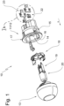
- a cooking appliance light is provided with the reference number 10 and in figure 1 shown in exploded view.
- the cooking appliance light 10 shown comprises a cooking appliance lamp socket 11 formed by a socket stone 12 which forms a receiving recess 14 on its top side facing a lamp glass 13 .
- the receiving recess 14 is delimited by a wall 15 and has an insertion opening 16 which is surrounded by a mounting flange 17 .
- a retaining ring 18 that can be inserted into the receiving recess 14 serves to fix the cooking device lamp socket 11 in a light recess of a cooking device wall.
- the retaining ring 18 also fixes the lamp glass 13 to the socket stone 12 and provides a retaining spring by means of which the lamp base 19 of a G9 lamp is locked in a socket recess of the socket stone 12 .
- the socket stone 12 On its underside facing away from the lamp glass 13, the socket stone 12 forms two sockets 21, each of which holds a socket contact 22 and a supply contact 23 in a manner to be described later.
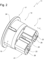
- FIG 2 shows the cooking appliance lamp socket 11 in a perspective view of its underside.
- the wall 15 carries a centering rib 24, by means of which the cooking appliance lamp socket 11 can be arranged in the correct position in the cooking appliance.
- the sockets 21 of the setting stone 12 are separated from one another by a ventilation gap 25 and each have a contact cavity 26.
- Each contact cavity 26 is accessible via an insertion opening 27, via each of which a socket contact 22 and a supply contact 23 can be introduced into the respective contact cavity 26 in the direction of insertion X.
- the insertion openings 27 are on the underside of the setting stone 12.
- the direction of insertion X is directed toward the lamp glass 12.
- figure 3 12 now shows the cooking appliance lamp socket 11 viewed from below, ie in the direction of insertion X.
- the insertion openings 27 of the contact cavities 26 can be seen very well in this representation.
- this representation allows an insight into the contact cavities 26 and the supply contact 23 located in each contact cavity and the socket contact 22 also located there.
- FIG. 1b shows the the figure 1 Removed arrangement of seated in the socket 21 socket contacts 22 and supply contacts 23 in an enlarged view.
- Each socket contact 22 has a flat plug 30 on its end facing the insertion opening 27. This is followed in the insertion direction X, ie in the direction of the lamp glass 13, by a clamping section 31 from which clamping lugs 32 are released.
- a contact section 34 is then arranged in front of the clamping section 31 and carries two fastening means 33 in the form of fastening arms 35 which are opposite one another and hold the clamping section 31 between them.
- the fastening arm 35 stretches from the contact section 34 counter to the insertion direction X in the direction of the underside of the socket stone 12 or in the direction of the flat plug 30.
- the direction of the lamp glass 13 or in the direction of insertion X forward lying end face 36 of the supply contact 23 serves as a support structure for fixing the socket contact 22.
- the supply contact 23 is a stamped and bent part with an essentially plate-like shape.
- the clamping lugs 32 are exhibited at an angle to the rolling sides.
- the mounting arms are in Figure 1B exhibited at an angle to the punched edges.
- the socket contact 22 also a stamped and bent part, has an approximately U-shaped or C-shaped cross-sectional contour.
- a first contact leg 40 is connected to a second contact leg 42 via a support leg 41, with the free ends of the first contact leg 40 and the second contact leg 42 moving counter to the insertion direction X in the direction of the insertion opening 27 of the socket 21, i.e. in the direction of the underside of the socket stone 12 are directed.
- the first contact limb 40 has a pressure spring 43 which is notched out of the material of the contact limb and is exhibited in a resiliently restoring manner in the direction of the second contact limb 42, ie in the interior of the U-shaped socket contact 22.
- the second contact leg 42 of the socket contact 22 is resiliently elastic away from the first contact leg 40, ie in the same direction as the pressure spring 43 is issued.
- figure 7 shows the setting stone 12 in a vertical sectional view along section line VV in figure 3 , In which case the representation of the seated socket contacts 22 and the seated supply contacts 23 has also been dispensed with here.
- each connecting piece 21 forms a contact cavity 26 which is accessible via an insertion opening 27 .
- a first accommodation space 50 and a second accommodation space 51 are formed within each contact cavity 26 .
- the first receiving space 50 runs through the contact cavity 26 as a diametrically extending slot 52 through the contact cavity 26, which is opposite to the insertion direction X, ie in the direction of the insertion opening 27, open.
- the second receiving space is arranged between the slot ends and shares a common receiving section 53 with the first receiving space.
- the location of the receiving spaces 50, 51 in the socket 21 of the socket stone 12 is also once again from figure 8 out, which is a sectional view according to VIII-VIII in figure 7 is.
- the socket contacts 22 and supply contacts 23 are not shown.
- the slot-like first receiving space 50 passes through the second receiving space 51.
- the common receiving space 53 is formed, in which the end face 36 meets the support leg 41 when the socket and supply contacts 22, 23 are inserted.
- the arrangement of socket contact and supply contact 23 in the receiving spaces 50, 51 then corresponds to that in figure 3 shown contact arrangement.
- FIG 5 shows the sectional view accordingly figure 7 with socket and supply contacts 22, 23 seated in the respective contact cavity 26 of each socket 21.
- the socket contact 22 must first be inserted into the second receiving space 51 in the insertion direction X in the socket block 12.
- the free end of the first contact leg 40 engages behind a protruding retaining lug 28, which is formed by the wall of the contact cavity 26, whereas the free end of the second contact leg 42 is located on an in figure 5 not visible wall section supports.
- the socket contact 22 experiences such a Prefixing that prevents the same from accidentally slipping out of the setting stone 12 during assembly.
- the supply contact 23 is pushed into the first receiving space 50, the slot 52.
- the insertion movement of the supply contact 23 in the insertion direction X ends when the end face 36 comes to rest on the inside of the support leg 51 of the socket contact 22, which sits in the common receiving section 53 of the first receiving space 50 and the second receiving space 51.
- the pressure spring 43 rests against the contact section 34 of the supply contact 23 and ensures the required electrical contact between socket contact 22 and supply contact 23.
- the second contact leg 42 of socket contact 22 sits in socket receptacle 29 of socket insulator 12, so that the socket contacts of a lamp in this embodiment of a G9 lamp 20 can contact them electrically.
- figure 4 shows the setting stone 12 together with the contacts used according to the section line IV-IV in FIG figure 3 .
- the supply contact 23 is pushed into the contact cavity 26 of the socket 21 in the insertion direction X and rests with its end face 36 on the support leg 41 of the socket contact 22 and holds it in the second receiving space 51 .
- the fastening arms 35 of the supply contact 23 because of their lateral spread directed towards the contact cavity wall, engage behind a fastening contour formed by the contact cavity wall, which is formed here as a wall projection 54 .
- a socket base 55 formed by socket insulator 12 serves as a movement limit stop in plug-in direction X, which delimits contact cavities 26 in plug-in direction X (see also figure 5 ).
- fastening arms 35 are spring-loaded fastening means that are spread outwards, i.e. in the direction of the contact cavity wall, these are initially displaced inwards when the supply contact 23 is pushed into the respective connection piece 21 until they have slid past the wall projection 54 .
- the spring-return elasticity of the material then leads to a spreading movement in the initial position, whereby the wall projection 54 is gripped behind, so that a pull-out movement of the supply contact 23 counter to the insertion direction X from the setting block 12 is reliably prevented.
- the fastening means are designed as plastically deformable fastening arms, they point in a straight line, ie not spread, before the completed assembly of the supply contact 23, against the insertion direction X or in the direction of the flat plug 30.
- a forming tool is inserted between the respective fastening arm 35 and the clamping section 31 located between the fastening arms 35, which spreads the fastening arms 35 outwards in the sense of plastic deformation until they securely grip behind the wall projection 54 and a retraction movement of the supply contact 23 counter to the insertion direction X is certain impede.
Landscapes
- Connecting Device With Holders (AREA)
- Fastening Of Light Sources Or Lamp Holders (AREA)
Claims (12)
- Douille de lampe pour appareil de cuisson (11), comprenant :- un bloc de douille (12),- au moins un contact d'alimentation (23) qui sert à connecter un conducteur de raccordement pour l'alimentation en tension d'une lampe,- au moins un contact de douille (22) qui connecté de façon électrique au contact d'alimentation (23) et qui sert à connecter un contact de culot de la lampe,- une cavité de contact (26) qui est formée par le bloc de douille (12) et à l'intérieur de laquelle le contact de douille (22) est agencé, et- le moyen de fixation (33) à l'aide desquels le contact d'alimentation (23) est fixé au bloc de douille (12),dans laquelle- le moyen de fixation (33) font partie intégrante du contact d'alimentation (23) et/ou sont joints par assemblage à celui-ci, et- le bloc de douille (12) présente un contour de fixation à l'intérieur duquel le moyen de fixation (33) du contact d'alimentation (23) s'engagent,caractérisée en ce que- le contact d'alimentation (23) et le contact de douille (22) sont deux composants distincts l'un de l'autre, et- le contact de douille (22) est maintenu par le contact d'alimentation (23) fixé au bloc de douille (12).
- Douille de lampe pour appareil de cuisson selon la revendication 1, caractérisée en ce que le bloc de douille (12) comporte un évidement de réception (14) sur sa face supérieure orientée en direction d'un verre de lampe (13).
- Douille de lampe d'appareil de cuisson selon la revendication 2, caractérisée en ce qu'une bague de retenue (18) est logée à l'intérieur de l'évidement de réception (14) et retient la douille de lampe d'appareil de cuisson (11) à l'intérieur d'un évidement de lampe d'un appareil de cuisson.
- Douille de lampe d'appareil de cuisson (11) selon l'une quelconque des revendications 1 à 3, caractérisée en ce que le contact d'alimentation (23) est agencé à l'intérieur de la cavité de contact (26) et est accessible par l'intermédiaire d'une ouverture d'insertion (27) de la cavité de contact (26).
- Douille de lampe d'appareil de cuisson (11) selon les revendications 2 et 4, caractérisée en ce que le contour de fixation est formé par les parois de la cavité de contact (26) et est engagé par l'arrière par les moyens de fixation (33) du contact d'alimentation (23).
- Douille de lampe d'appareil de cuisson (11) selon l'une quelconque des revendications précédentes, caractérisée en ce que les moyens de fixation (33) se présentent sous la forme d'au moins un bras de fixation (35) qui est connecté au contact d'alimentation (23) de façon plastiquement déformable ou avec une élasticité de rappel.
- Douille de lampe d'appareil de cuisson (11) selon les revendications 2, 4, 5 et 6, caractérisée en ce que le contour de fixation se présente sous la forme d'une saillie de paroi qui est engagée par l'arrière par le bras de fixation (35).
- Douille de lampe d'appareil de cuisson (11) selon les revendications 1 et 4, caractérisée en ce que la cavité de contact (26) présente un premier espace de réception (50) pour le contact de douille (22) et un second espace de réception (51) pour le contact d'alimentation (23), et en ce que le premier espace de réception (50) et le second espace de réception (51) partagent une section de réception commune (53).
- Douille de lampe d'appareil de cuisson (11) selon les revendications 3 et 8, caractérisée en ce que le contact de douille (22) et le contact d'alimentation (23) sont logés à l'intérieur de la section de réception commune (53) et le contact de douille (22) est maintenu en prenant appui sur le contact d'alimentation (23).
- Douille de lampe d'appareil de cuisson (11) selon la revendication 9, caractérisée en ce que le contact de douille (22) et le contact d'alimentation (23) sont insérés à l'intérieur de la cavité de contact (26) le long d'une direction d'insertion commune (X) à travers l'ouverture d'insertion (27), et en ce que le contact de douille (22) est disposé en amont du contact d'alimentation (23) dans la direction d'insertion (X).
- Douille de lampe d'appareil de cuisson selon la revendication 4, caractérisée en ce que l'ouverture d'insertion (27) est située sur la face inférieure du bloc de douille (12).
- Douille de lampe d'appareil de cuisson selon les revendications 10 et 11, caractérisée en ce que la direction d'insertion est orientée en direction d'un verre de lampe (13).
Applications Claiming Priority (1)
| Application Number | Priority Date | Filing Date | Title |
|---|---|---|---|
| DE102021112796.3A DE102021112796B3 (de) | 2021-05-18 | 2021-05-18 | Lampenfassung mit ungenieteter Kontaktanbindung |
Publications (2)
| Publication Number | Publication Date |
|---|---|
| EP4092837A1 EP4092837A1 (fr) | 2022-11-23 |
| EP4092837B1 true EP4092837B1 (fr) | 2023-08-16 |
Family
ID=80449142
Family Applications (1)
| Application Number | Title | Priority Date | Filing Date |
|---|---|---|---|
| EP22158398.2A Active EP4092837B1 (fr) | 2021-05-18 | 2022-02-24 | Douille de lampe d'appareils de cuisson à liaison de contact non rivée |
Country Status (5)
| Country | Link |
|---|---|
| US (1) | US11843207B2 (fr) |
| EP (1) | EP4092837B1 (fr) |
| CN (1) | CN115377765A (fr) |
| DE (1) | DE102021112796B3 (fr) |
| PL (1) | PL4092837T3 (fr) |
Citations (1)
| Publication number | Priority date | Publication date | Assignee | Title |
|---|---|---|---|---|
| EP0320875A2 (fr) * | 1987-12-15 | 1989-06-21 | Bosch-Siemens HausgerÀ¤te GmbH | Dispositif d'éclairage pour appareils domestiques tels que fours |
Family Cites Families (9)
| Publication number | Priority date | Publication date | Assignee | Title |
|---|---|---|---|---|
| US3810072A (en) | 1972-11-22 | 1974-05-07 | Microdot Inc | Socket |
| US4804343A (en) * | 1988-04-11 | 1989-02-14 | General Motors Corporation | Lamp socket assembly |
| DE19860588C2 (de) * | 1998-12-29 | 2001-03-01 | Schnippering Hugo Gmbh Co Kg | Lampenfassung aus Isolierstoff für H 7-Lampen |
| DE29922089U1 (de) | 1999-12-16 | 2000-03-30 | BJB GmbH & Co.KG, 59755 Arnsberg | Elektrischer Anschlußkontakt und Lampenfassung mit einem solchen Kontakt |
| DE10163056B4 (de) * | 2001-12-21 | 2004-07-08 | Bjb Gmbh & Co.Kg | Lampenfassung |
| DE102006002667B4 (de) | 2006-01-19 | 2007-11-29 | Bjb Gmbh & Co.Kg | Elektrische Leuchte, insbesondere zum Einbau in Küchengeräte |
| KR101614543B1 (ko) * | 2009-09-07 | 2016-04-22 | 타이코에이엠피 주식회사 | 웨지벌브용 소켓 |
| FR2977391B1 (fr) * | 2011-06-30 | 2016-08-05 | Tbi | Douille hybride pour ampoule mono-filament ou bi-filament |
| DE102021112797B3 (de) * | 2021-05-18 | 2022-06-23 | Bjb Gmbh & Co. Kg | Lampenfassung mit Belüftungskanal |
-
2021
- 2021-05-18 DE DE102021112796.3A patent/DE102021112796B3/de active Active
-
2022
- 2022-02-24 PL PL22158398.2T patent/PL4092837T3/pl unknown
- 2022-02-24 EP EP22158398.2A patent/EP4092837B1/fr active Active
- 2022-03-20 US US17/699,127 patent/US11843207B2/en active Active
- 2022-04-18 CN CN202210401195.5A patent/CN115377765A/zh active Pending
Patent Citations (1)
| Publication number | Priority date | Publication date | Assignee | Title |
|---|---|---|---|---|
| EP0320875A2 (fr) * | 1987-12-15 | 1989-06-21 | Bosch-Siemens HausgerÀ¤te GmbH | Dispositif d'éclairage pour appareils domestiques tels que fours |
Also Published As
| Publication number | Publication date |
|---|---|
| CN115377765A (zh) | 2022-11-22 |
| US11843207B2 (en) | 2023-12-12 |
| DE102021112796B3 (de) | 2022-06-23 |
| US20220376449A1 (en) | 2022-11-24 |
| EP4092837A1 (fr) | 2022-11-23 |
| PL4092837T3 (pl) | 2024-02-19 |
Similar Documents
| Publication | Publication Date | Title |
|---|---|---|
| DE10126957B4 (de) | Steckverbindung mit Mitteln zur Verhinderung eines unvollständig verbundenen Zustands | |
| DE20007001U1 (de) | Stecker mit einer Hülse | |
| DE2409075A1 (de) | Elektrischer verbinder | |
| EP1662620A2 (fr) | Connexion électrique | |
| DE69500937T2 (de) | Lampenfassung | |
| DE2811774A1 (de) | Elektrischer buchsenkontakt | |
| EP1443609B1 (fr) | Dispositif de retenue pour une pièce d'insertion de contacts dans un boîtier de connecteur | |
| DE102012109059B4 (de) | Halterung eines Leuchtmittels in der Öffnung eines Reflektors | |
| DE29823160U1 (de) | Lampenfassung aus Isolierstoff für H 7-Lampen | |
| WO2020212122A1 (fr) | Borne à ressort et procédé de fabrication d'une borne à ressort | |
| EP3633802A1 (fr) | Prise de courant d'appareil, connecteur d'appareil et système de connecteur d'appareil | |
| DE69901151T2 (de) | Elektrischer und/oder optischer Steckverbinder | |
| DE102021112796B3 (de) | Lampenfassung mit ungenieteter Kontaktanbindung | |
| DE4205974C1 (en) | Electrical plug connector with built-in latching for pins - provides section formed on housing that locates against pin flange and is held by latch stage | |
| DE19860588C2 (de) | Lampenfassung aus Isolierstoff für H 7-Lampen | |
| EP1528639A1 (fr) | Boítier de connecteur ayant un pont de court-circuit | |
| BE1026101B1 (de) | Kontaktelement mit einem Kontaktkörper und einem daran angeordneten Federelement | |
| DE202016102265U1 (de) | Befestigungselement zur Verbindung zwischen einer LED-Platine und einem Leuchten-Bauteil | |
| DE202021102681U1 (de) | Lampenfassung mit ungenieteter Kontaktanbindung | |
| WO2019086066A1 (fr) | Connecteur enfichable | |
| EP1401062B1 (fr) | Système de contact à fiche pour appareils ménagers | |
| DE19854440A1 (de) | Verlängerungsstück für Leuchtstofflampen | |
| EP0664583A1 (fr) | Douille pour petite lampe à incandescence | |
| DE102004030109B4 (de) | Verbindungsvorrichtung zum lösbaren Verbinden einer Lampe mit einem Reflektor | |
| DE102006022206B3 (de) | Elektrischer Steckanschluß |
Legal Events
| Date | Code | Title | Description |
|---|---|---|---|
| PUAI | Public reference made under article 153(3) epc to a published international application that has entered the european phase |
Free format text: ORIGINAL CODE: 0009012 |
|
| STAA | Information on the status of an ep patent application or granted ep patent |
Free format text: STATUS: THE APPLICATION HAS BEEN PUBLISHED |
|
| STAA | Information on the status of an ep patent application or granted ep patent |
Free format text: STATUS: REQUEST FOR EXAMINATION WAS MADE |
|
| AK | Designated contracting states |
Kind code of ref document: A1 Designated state(s): AL AT BE BG CH CY CZ DE DK EE ES FI FR GB GR HR HU IE IS IT LI LT LU LV MC MK MT NL NO PL PT RO RS SE SI SK SM TR |
|
| 17P | Request for examination filed |
Effective date: 20221114 |
|
| RBV | Designated contracting states (corrected) |
Designated state(s): AL AT BE BG CH CY CZ DE DK EE ES FI FR GB GR HR HU IE IS IT LI LT LU LV MC MK MT NL NO PL PT RO RS SE SI SK SM TR |
|
| STAA | Information on the status of an ep patent application or granted ep patent |
Free format text: STATUS: EXAMINATION IS IN PROGRESS |
|
| 17Q | First examination report despatched |
Effective date: 20230126 |
|
| GRAP | Despatch of communication of intention to grant a patent |
Free format text: ORIGINAL CODE: EPIDOSNIGR1 |
|
| STAA | Information on the status of an ep patent application or granted ep patent |
Free format text: STATUS: GRANT OF PATENT IS INTENDED |
|
| RIC1 | Information provided on ipc code assigned before grant |
Ipc: H01R 13/428 20060101ALN20230406BHEP Ipc: H01R 4/48 20060101ALN20230406BHEP Ipc: H01R 33/06 20060101ALI20230406BHEP Ipc: H01R 13/432 20060101ALI20230406BHEP Ipc: H01R 13/08 20060101AFI20230406BHEP |
|
| INTG | Intention to grant announced |
Effective date: 20230510 |
|
| GRAS | Grant fee paid |
Free format text: ORIGINAL CODE: EPIDOSNIGR3 |
|
| GRAA | (expected) grant |
Free format text: ORIGINAL CODE: 0009210 |
|
| STAA | Information on the status of an ep patent application or granted ep patent |
Free format text: STATUS: THE PATENT HAS BEEN GRANTED |
|
| AK | Designated contracting states |
Kind code of ref document: B1 Designated state(s): AL AT BE BG CH CY CZ DE DK EE ES FI FR GB GR HR HU IE IS IT LI LT LU LV MC MK MT NL NO PL PT RO RS SE SI SK SM TR |
|
| REG | Reference to a national code |
Ref country code: CH Ref legal event code: EP |
|
| REG | Reference to a national code |
Ref country code: DE Ref legal event code: R096 Ref document number: 502022000089 Country of ref document: DE |
|
| REG | Reference to a national code |
Ref country code: IE Ref legal event code: FG4D Free format text: LANGUAGE OF EP DOCUMENT: GERMAN |
|
| REG | Reference to a national code |
Ref country code: LT Ref legal event code: MG9D |
|
| REG | Reference to a national code |
Ref country code: NL Ref legal event code: MP Effective date: 20230816 |
|
| P01 | Opt-out of the competence of the unified patent court (upc) registered |
Effective date: 20231211 |
|
| PG25 | Lapsed in a contracting state [announced via postgrant information from national office to epo] |
Ref country code: GR Free format text: LAPSE BECAUSE OF FAILURE TO SUBMIT A TRANSLATION OF THE DESCRIPTION OR TO PAY THE FEE WITHIN THE PRESCRIBED TIME-LIMIT Effective date: 20231117 |
|
| PG25 | Lapsed in a contracting state [announced via postgrant information from national office to epo] |
Ref country code: IS Free format text: LAPSE BECAUSE OF FAILURE TO SUBMIT A TRANSLATION OF THE DESCRIPTION OR TO PAY THE FEE WITHIN THE PRESCRIBED TIME-LIMIT Effective date: 20231216 |
|
| PG25 | Lapsed in a contracting state [announced via postgrant information from national office to epo] |
Ref country code: SE Free format text: LAPSE BECAUSE OF FAILURE TO SUBMIT A TRANSLATION OF THE DESCRIPTION OR TO PAY THE FEE WITHIN THE PRESCRIBED TIME-LIMIT Effective date: 20230816 Ref country code: RS Free format text: LAPSE BECAUSE OF FAILURE TO SUBMIT A TRANSLATION OF THE DESCRIPTION OR TO PAY THE FEE WITHIN THE PRESCRIBED TIME-LIMIT Effective date: 20230816 Ref country code: PT Free format text: LAPSE BECAUSE OF FAILURE TO SUBMIT A TRANSLATION OF THE DESCRIPTION OR TO PAY THE FEE WITHIN THE PRESCRIBED TIME-LIMIT Effective date: 20231218 Ref country code: NO Free format text: LAPSE BECAUSE OF FAILURE TO SUBMIT A TRANSLATION OF THE DESCRIPTION OR TO PAY THE FEE WITHIN THE PRESCRIBED TIME-LIMIT Effective date: 20231116 Ref country code: NL Free format text: LAPSE BECAUSE OF FAILURE TO SUBMIT A TRANSLATION OF THE DESCRIPTION OR TO PAY THE FEE WITHIN THE PRESCRIBED TIME-LIMIT Effective date: 20230816 Ref country code: LV Free format text: LAPSE BECAUSE OF FAILURE TO SUBMIT A TRANSLATION OF THE DESCRIPTION OR TO PAY THE FEE WITHIN THE PRESCRIBED TIME-LIMIT Effective date: 20230816 Ref country code: LT Free format text: LAPSE BECAUSE OF FAILURE TO SUBMIT A TRANSLATION OF THE DESCRIPTION OR TO PAY THE FEE WITHIN THE PRESCRIBED TIME-LIMIT Effective date: 20230816 Ref country code: IS Free format text: LAPSE BECAUSE OF FAILURE TO SUBMIT A TRANSLATION OF THE DESCRIPTION OR TO PAY THE FEE WITHIN THE PRESCRIBED TIME-LIMIT Effective date: 20231216 Ref country code: HR Free format text: LAPSE BECAUSE OF FAILURE TO SUBMIT A TRANSLATION OF THE DESCRIPTION OR TO PAY THE FEE WITHIN THE PRESCRIBED TIME-LIMIT Effective date: 20230816 Ref country code: GR Free format text: LAPSE BECAUSE OF FAILURE TO SUBMIT A TRANSLATION OF THE DESCRIPTION OR TO PAY THE FEE WITHIN THE PRESCRIBED TIME-LIMIT Effective date: 20231117 Ref country code: FI Free format text: LAPSE BECAUSE OF FAILURE TO SUBMIT A TRANSLATION OF THE DESCRIPTION OR TO PAY THE FEE WITHIN THE PRESCRIBED TIME-LIMIT Effective date: 20230816 |
|
| PG25 | Lapsed in a contracting state [announced via postgrant information from national office to epo] |
Ref country code: ES Free format text: LAPSE BECAUSE OF FAILURE TO SUBMIT A TRANSLATION OF THE DESCRIPTION OR TO PAY THE FEE WITHIN THE PRESCRIBED TIME-LIMIT Effective date: 20230816 |
|
| PG25 | Lapsed in a contracting state [announced via postgrant information from national office to epo] |
Ref country code: SM Free format text: LAPSE BECAUSE OF FAILURE TO SUBMIT A TRANSLATION OF THE DESCRIPTION OR TO PAY THE FEE WITHIN THE PRESCRIBED TIME-LIMIT Effective date: 20230816 Ref country code: RO Free format text: LAPSE BECAUSE OF FAILURE TO SUBMIT A TRANSLATION OF THE DESCRIPTION OR TO PAY THE FEE WITHIN THE PRESCRIBED TIME-LIMIT Effective date: 20230816 Ref country code: ES Free format text: LAPSE BECAUSE OF FAILURE TO SUBMIT A TRANSLATION OF THE DESCRIPTION OR TO PAY THE FEE WITHIN THE PRESCRIBED TIME-LIMIT Effective date: 20230816 Ref country code: EE Free format text: LAPSE BECAUSE OF FAILURE TO SUBMIT A TRANSLATION OF THE DESCRIPTION OR TO PAY THE FEE WITHIN THE PRESCRIBED TIME-LIMIT Effective date: 20230816 Ref country code: DK Free format text: LAPSE BECAUSE OF FAILURE TO SUBMIT A TRANSLATION OF THE DESCRIPTION OR TO PAY THE FEE WITHIN THE PRESCRIBED TIME-LIMIT Effective date: 20230816 Ref country code: CZ Free format text: LAPSE BECAUSE OF FAILURE TO SUBMIT A TRANSLATION OF THE DESCRIPTION OR TO PAY THE FEE WITHIN THE PRESCRIBED TIME-LIMIT Effective date: 20230816 Ref country code: SK Free format text: LAPSE BECAUSE OF FAILURE TO SUBMIT A TRANSLATION OF THE DESCRIPTION OR TO PAY THE FEE WITHIN THE PRESCRIBED TIME-LIMIT Effective date: 20230816 |
|
| REG | Reference to a national code |
Ref country code: DE Ref legal event code: R097 Ref document number: 502022000089 Country of ref document: DE |
|
| PLBE | No opposition filed within time limit |
Free format text: ORIGINAL CODE: 0009261 |
|
| STAA | Information on the status of an ep patent application or granted ep patent |
Free format text: STATUS: NO OPPOSITION FILED WITHIN TIME LIMIT |
|
| 26N | No opposition filed |
Effective date: 20240517 |
|
| PG25 | Lapsed in a contracting state [announced via postgrant information from national office to epo] |
Ref country code: SI Free format text: LAPSE BECAUSE OF FAILURE TO SUBMIT A TRANSLATION OF THE DESCRIPTION OR TO PAY THE FEE WITHIN THE PRESCRIBED TIME-LIMIT Effective date: 20230816 |
|
| PG25 | Lapsed in a contracting state [announced via postgrant information from national office to epo] |
Ref country code: MC Free format text: LAPSE BECAUSE OF FAILURE TO SUBMIT A TRANSLATION OF THE DESCRIPTION OR TO PAY THE FEE WITHIN THE PRESCRIBED TIME-LIMIT Effective date: 20230816 |
|
| PG25 | Lapsed in a contracting state [announced via postgrant information from national office to epo] |
Ref country code: LU Free format text: LAPSE BECAUSE OF NON-PAYMENT OF DUE FEES Effective date: 20240224 |
|
| PG25 | Lapsed in a contracting state [announced via postgrant information from national office to epo] |
Ref country code: LU Free format text: LAPSE BECAUSE OF NON-PAYMENT OF DUE FEES Effective date: 20240224 |
|
| PG25 | Lapsed in a contracting state [announced via postgrant information from national office to epo] |
Ref country code: BG Free format text: LAPSE BECAUSE OF FAILURE TO SUBMIT A TRANSLATION OF THE DESCRIPTION OR TO PAY THE FEE WITHIN THE PRESCRIBED TIME-LIMIT Effective date: 20230816 |
|
| PG25 | Lapsed in a contracting state [announced via postgrant information from national office to epo] |
Ref country code: BG Free format text: LAPSE BECAUSE OF FAILURE TO SUBMIT A TRANSLATION OF THE DESCRIPTION OR TO PAY THE FEE WITHIN THE PRESCRIBED TIME-LIMIT Effective date: 20230816 |
|
| REG | Reference to a national code |
Ref country code: BE Ref legal event code: MM Effective date: 20240229 |
|
| PG25 | Lapsed in a contracting state [announced via postgrant information from national office to epo] |
Ref country code: BE Free format text: LAPSE BECAUSE OF NON-PAYMENT OF DUE FEES Effective date: 20240229 |
|
| PG25 | Lapsed in a contracting state [announced via postgrant information from national office to epo] |
Ref country code: FR Free format text: LAPSE BECAUSE OF NON-PAYMENT OF DUE FEES Effective date: 20240229 |
|
| PG25 | Lapsed in a contracting state [announced via postgrant information from national office to epo] |
Ref country code: IE Free format text: LAPSE BECAUSE OF NON-PAYMENT OF DUE FEES Effective date: 20240224 |
|
| PG25 | Lapsed in a contracting state [announced via postgrant information from national office to epo] |
Ref country code: IE Free format text: LAPSE BECAUSE OF NON-PAYMENT OF DUE FEES Effective date: 20240224 Ref country code: FR Free format text: LAPSE BECAUSE OF NON-PAYMENT OF DUE FEES Effective date: 20240229 Ref country code: BE Free format text: LAPSE BECAUSE OF NON-PAYMENT OF DUE FEES Effective date: 20240229 |
|
| PG25 | Lapsed in a contracting state [announced via postgrant information from national office to epo] |
Ref country code: CY Free format text: LAPSE BECAUSE OF FAILURE TO SUBMIT A TRANSLATION OF THE DESCRIPTION OR TO PAY THE FEE WITHIN THE PRESCRIBED TIME-LIMIT; INVALID AB INITIO Effective date: 20220224 |
|
| REG | Reference to a national code |
Ref country code: CH Ref legal event code: PL |
|
| PG25 | Lapsed in a contracting state [announced via postgrant information from national office to epo] |
Ref country code: CH Free format text: LAPSE BECAUSE OF NON-PAYMENT OF DUE FEES Effective date: 20250228 |
|
| PG25 | Lapsed in a contracting state [announced via postgrant information from national office to epo] |
Ref country code: TR Free format text: LAPSE BECAUSE OF FAILURE TO SUBMIT A TRANSLATION OF THE DESCRIPTION OR TO PAY THE FEE WITHIN THE PRESCRIBED TIME-LIMIT Effective date: 20230816 |
|
| PGFP | Annual fee paid to national office [announced via postgrant information from national office to epo] |
Ref country code: DE Payment date: 20260217 Year of fee payment: 5 |
|
| PGFP | Annual fee paid to national office [announced via postgrant information from national office to epo] |
Ref country code: AT Payment date: 20260301 Year of fee payment: 5 |
|
| PGFP | Annual fee paid to national office [announced via postgrant information from national office to epo] |
Ref country code: IT Payment date: 20260227 Year of fee payment: 5 |
|
| PGFP | Annual fee paid to national office [announced via postgrant information from national office to epo] |
Ref country code: PL Payment date: 20260212 Year of fee payment: 5 |