EP4096972B1 - Kleinflächiges wischen - Google Patents
Kleinflächiges wischen Download PDFInfo
- Publication number
- EP4096972B1 EP4096972B1 EP21700295.5A EP21700295A EP4096972B1 EP 4096972 B1 EP4096972 B1 EP 4096972B1 EP 21700295 A EP21700295 A EP 21700295A EP 4096972 B1 EP4096972 B1 EP 4096972B1
- Authority
- EP
- European Patent Office
- Prior art keywords
- wiper blade
- drive shaft
- wiping
- wiping system
- rotation
- Prior art date
- Legal status (The legal status is an assumption and is not a legal conclusion. Google has not performed a legal analysis and makes no representation as to the accuracy of the status listed.)
- Active
Links
Images





Classifications
-
- B—PERFORMING OPERATIONS; TRANSPORTING
- B60—VEHICLES IN GENERAL
- B60S—SERVICING, CLEANING, REPAIRING, SUPPORTING, LIFTING, OR MANOEUVRING OF VEHICLES, NOT OTHERWISE PROVIDED FOR
- B60S1/00—Cleaning of vehicles
- B60S1/02—Cleaning windscreens, windows or optical devices
- B60S1/04—Wipers or the like, e.g. scrapers
- B60S1/32—Wipers or the like, e.g. scrapers characterised by constructional features of wiper blade arms or blades
- B60S1/34—Wiper arms; Mountings therefor
- B60S1/3425—Constructional aspects of the arm
- B60S1/3445—Joints between elements
- B60S1/3459—Joints between elements the element being a mounting head and a shaft
-
- B—PERFORMING OPERATIONS; TRANSPORTING
- B60—VEHICLES IN GENERAL
- B60S—SERVICING, CLEANING, REPAIRING, SUPPORTING, LIFTING, OR MANOEUVRING OF VEHICLES, NOT OTHERWISE PROVIDED FOR
- B60S1/00—Cleaning of vehicles
- B60S1/02—Cleaning windscreens, windows or optical devices
- B60S1/56—Cleaning windscreens, windows or optical devices specially adapted for cleaning other parts or devices than front windows or windscreens
- B60S1/566—Cleaning windscreens, windows or optical devices specially adapted for cleaning other parts or devices than front windows or windscreens including wiping devices
-
- B—PERFORMING OPERATIONS; TRANSPORTING
- B60—VEHICLES IN GENERAL
- B60S—SERVICING, CLEANING, REPAIRING, SUPPORTING, LIFTING, OR MANOEUVRING OF VEHICLES, NOT OTHERWISE PROVIDED FOR
- B60S1/00—Cleaning of vehicles
- B60S1/02—Cleaning windscreens, windows or optical devices
- B60S1/04—Wipers or the like, e.g. scrapers
- B60S1/32—Wipers or the like, e.g. scrapers characterised by constructional features of wiper blade arms or blades
- B60S1/38—Wiper blades
- B60S1/3848—Flat-type wiper blade, i.e. without harness
- B60S1/3872—Flat-type wiper blade, i.e. without harness without connector, e.g. connection to wiper arm via squeegee or vertebra
-
- B—PERFORMING OPERATIONS; TRANSPORTING
- B60—VEHICLES IN GENERAL
- B60S—SERVICING, CLEANING, REPAIRING, SUPPORTING, LIFTING, OR MANOEUVRING OF VEHICLES, NOT OTHERWISE PROVIDED FOR
- B60S1/00—Cleaning of vehicles
- B60S1/02—Cleaning windscreens, windows or optical devices
- B60S1/04—Wipers or the like, e.g. scrapers
- B60S1/32—Wipers or the like, e.g. scrapers characterised by constructional features of wiper blade arms or blades
- B60S1/34—Wiper arms; Mountings therefor
- B60S1/3425—Constructional aspects of the arm
- B60S1/3427—Arm piece, link piece and mounting head formed as one element
-
- B—PERFORMING OPERATIONS; TRANSPORTING
- B60—VEHICLES IN GENERAL
- B60S—SERVICING, CLEANING, REPAIRING, SUPPORTING, LIFTING, OR MANOEUVRING OF VEHICLES, NOT OTHERWISE PROVIDED FOR
- B60S1/00—Cleaning of vehicles
- B60S1/02—Cleaning windscreens, windows or optical devices
- B60S1/04—Wipers or the like, e.g. scrapers
- B60S1/32—Wipers or the like, e.g. scrapers characterised by constructional features of wiper blade arms or blades
- B60S1/34—Wiper arms; Mountings therefor
- B60S1/3425—Constructional aspects of the arm
- B60S1/3436—Mounting heads
- B60S1/344—Flat-type mounting heads
-
- B—PERFORMING OPERATIONS; TRANSPORTING
- B60—VEHICLES IN GENERAL
- B60S—SERVICING, CLEANING, REPAIRING, SUPPORTING, LIFTING, OR MANOEUVRING OF VEHICLES, NOT OTHERWISE PROVIDED FOR
- B60S1/00—Cleaning of vehicles
- B60S1/02—Cleaning windscreens, windows or optical devices
- B60S1/04—Wipers or the like, e.g. scrapers
- B60S1/32—Wipers or the like, e.g. scrapers characterised by constructional features of wiper blade arms or blades
- B60S1/34—Wiper arms; Mountings therefor
- B60S1/3425—Constructional aspects of the arm
- B60S1/3443—Wiper shafts
-
- B—PERFORMING OPERATIONS; TRANSPORTING
- B60—VEHICLES IN GENERAL
- B60S—SERVICING, CLEANING, REPAIRING, SUPPORTING, LIFTING, OR MANOEUVRING OF VEHICLES, NOT OTHERWISE PROVIDED FOR
- B60S1/00—Cleaning of vehicles
- B60S1/02—Cleaning windscreens, windows or optical devices
- B60S1/46—Cleaning windscreens, windows or optical devices using liquid; Windscreen washers
- B60S1/48—Liquid supply therefor
- B60S1/52—Arrangement of nozzles; Liquid spreading means
- B60S1/522—Arrangement of nozzles; Liquid spreading means moving liquid spreading means, e.g. arranged in wiper arms
- B60S1/524—Arrangement of nozzles; Liquid spreading means moving liquid spreading means, e.g. arranged in wiper arms arranged in wiper blades
-
- B—PERFORMING OPERATIONS; TRANSPORTING
- B60—VEHICLES IN GENERAL
- B60S—SERVICING, CLEANING, REPAIRING, SUPPORTING, LIFTING, OR MANOEUVRING OF VEHICLES, NOT OTHERWISE PROVIDED FOR
- B60S1/00—Cleaning of vehicles
- B60S1/02—Cleaning windscreens, windows or optical devices
- B60S1/04—Wipers or the like, e.g. scrapers
- B60S1/32—Wipers or the like, e.g. scrapers characterised by constructional features of wiper blade arms or blades
- B60S1/38—Wiper blades
- B60S2001/3812—Means of supporting or holding the squeegee or blade rubber
- B60S2001/3825—Means of supporting or holding the squeegee or blade rubber the squeegee mounted directly to or in wiper blade arm
Definitions
- the present invention relates to the field of wiping, and more particularly the field of wiping systems dedicated to motor vehicles. It relates to a wiping system comprising a shaft and a broom, and to a shaft and a broom as such of such a wiping system.
- a wiping system comprising at least one blade for wiping a glass surface, such as for example a windshield.
- a wiper blade is driven, via an arm, by a drive motor between two extreme positions.
- the wiper blade is linked to the arm via a ball joint, which requires complex connections.
- These wiping solutions are suitable for a large glazed surface, but less so for small surfaces due to their bulk, their cost, and their complexity.
- a general object of the invention is to propose a reliable and simple wiping solution, particularly suitable for wiping a small surface such as that of a camera for an autonomous vehicle.
- a wiping blade is proposed for a wiping system, in particular for wiping a camera of a motor vehicle.
- the blade comprises a connection device capable of a removable connection with a drive shaft of the wiper blade, this connection device comprising a first orientation which allows assembly and disassembly relative to a drive shaft , and a second orientation which does not allow this assembly and disassembly.
- connection device further comprises an opening at one end of the wiper blade, comprising at least two enlarged portions for its assembly and disassembly.
- the broom further comprises an anti-rotation means, in particular by at least one protuberance at the level of an opening of its connection device or by a flange comprising at least one housing for cooperating with at least one stop of a drive shaft.
- the broom further comprises a mount forming slides for the removable fixation by translation of a wiping element intended to come into contact with the surface to be wiped.
- a wiping system which according to another aspect of the invention comprises a drive shaft and a wiping blade as described above, said blade being removably fixed on this drive shaft.
- the system further comprises an operating configuration in which an elastic means exerts a force on the wiper blade tending to keep it abutting against at least one stop of the drive shaft, in particular a pin , to lock the wiper blade in this operating configuration.
- the wiper blade and the drive shaft comprise respective connection devices configured to allow their assembly and/or disassembly by their successive actuation according to a first relative translation movement parallel to the axis of the drive shaft.
- the wiper blade and the drive shaft comprise respective anti-rotation means configured to form an anti-rotation device of the wiper blade relative to the drive shaft in said configuration of functioning.
- the drive shaft comprises a first portion with grooves forming an anti-rotation means
- the wiper blade comprises an opening with protuberances of format corresponding to the grooves, configured to be housed in the grooves in said configuration operation of the wiping system and form an anti-rotation device.
- the drive shaft comprises a pin forming an anti-rotation means and a locking stop
- the wiper blade comprising an anti-rotation collar comprising housings configured to cooperate with the pin in said operating configuration of the system wiping, thus forming an anti-rotation means and means for locking the wiper blade to the drive shaft.
- the elastic means comprises an elastic washer, in particular arranged between two flat washers.
- a camera or lighting device for an autonomous vehicle which according to another aspect of the invention comprises at least one wiping system as described above.
- a vehicle preferably an autonomous vehicle, which according to another aspect of the invention comprises a wiping system, a camera or a lighting device as described above.
- THE figures 1 to 11 illustrate a wiping system according to a first embodiment of the invention.
- This wiping system comprises on the one hand a drive shaft 1, which will also be more simply called shaft 1, or arm, intended to be driven in rotation on itself around its longitudinal axis by a motor, not shown , and on the other hand a wiping blade 20 comprising a wiping element 21 designed to remain in contact with a surface to be wiped, not shown.
- the wiping blade 20 is rotated by the shaft 1, allowing its wiping element 21 to wipe the surface.
- the wiping blade 20 is removably mounted on the shaft 1, according to a user-friendly, simple and reliable solution, as will be detailed below.
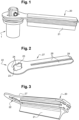
- FIG 2 represents the mount 27 of the wiper blade 20, which comprises a first end forming a connection device 22, capable of cooperating with the shaft 1, from which extend two flat, rectilinear and parallel blades 28, separated by a slot 29, to a second end of the wiper blade 20 opposite the connection device 22.
- This connection device 22 has a generally circular external shape, in the shape of a disc, and comprises a central opening fulfilling more particularly the function of connection.
- This opening generally has a circular shape, enlarged by a rectangular part forming two enlarged portions 23 relative to the circular opening, that is to say increasing the dimension of the opening. Between these two enlarged portions 23, the opening generally comprises a circular part, interrupted by two slots or protuberances 24 narrowing the opening, extending towards the center of the connection device 22.
- the mount 27 forms a rigid frame, preferably in metal, of the wiper blade 20.
- FIG. 3 illustrates the wiping blade 20, on which a wiping element 21 is mounted on the frame 27.
- the wiping element 21 comprises lateral grooves allowing cooperation with the blades 28 of the frame 27.
- the wiping element 21 can thus be translated in sliding connection along the blades 28 of the frame.
- the wiping element 21 also comprises an extension, opposite the mount 27, forming a wiping blade intended for a contact with the surface to be wiped, in a known manner.
- a tip not shown, can possibly be added to block the wiping element 21 after its assembly on the mount 27.
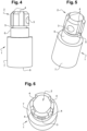
- THE figures 4 to 6 represent more particularly the shaft 1 of the wiping system. It comprises a first end forming a connection device 2 intended to cooperate with the wiper blade 20. This first end comprises a first portion having grooves 4 extending parallel to the axis of the shaft 1 on its periphery. This end further comprises a through cylindrical opening 3, perpendicular to the axis of the shaft 1, intended to receive a pin 13, for example visible on the Figure 9 .
- the shaft 1 comprises a second portion 5 of circular section of reduced diameter, corresponding substantially to the diameter measured from one groove 4 to another of the first portion. It then comprises a third portion 6 of larger diameter than the second portion, corresponding substantially to the diameter of the first portion apart from the grooves 4. Finally, it comprises a fourth portion 7 of even larger diameter, which extends up to at a second end 9 intended for a connection with a drive motor, not shown.
- the wiping system further comprises an elastic means, shown on the Figure 7 , intended for mounting on shaft 1, to cooperate with the wiper blade, as will be specified later.
- the elastic means comprises two flat washers 14 arranged on either side of an elastic washer 15, for example of the onduflex ® type.
- FIGS. 8 and 9 represent the shaft 1 on which the elastic means is mounted. It appears that a first flat washer 14 rests on the end of the fourth portion 7 of largest diameter of the shaft, the two other washers 14, 15 coming to rest on this first flat washer 14.
- Figure 9 further represents a pin 13 inserted in the aforementioned cylindrical opening 3 of the shaft 1.
- FIG 1 represents the fully assembled wiping system.
- THE figures 10 and 11 represent this wiping system mounted but removing certain elements to better visualize certain details, in particular the relative positioning of the different elements at the level of their connection.
- the Figure 11 allows you to visualize the positioning seen from below of the mount 27 on the shaft 1.
- Assembling the wiping system first includes mounting the elastic means on the shaft 1, then the pin 13 which secures everything together. At this stage, the wiping system is in the state represented by the Figure 9 .
- the mount 27 of the wiper blade is then mounted on the shaft 1. Its connection device 22 is brought close to the corresponding connection device 2 of the shaft 1. For this, the mount 27 is oriented so that its widened portions 23 come opposite the pin 13. Their dimensions are designed to allow the passage of the pin 13 through the opening formed in the connection device 22 of the mount, which represents the female connectors of the connection.
- the protuberances 24 come opposite the grooves 4: these shapes are provided so that the protuberances 24 can penetrate into the grooves 4.
- the mount 27 can be translated along the shaft 1. This translation is continued until the mount 27 comes into contact with a flat washer 14 of the elastic means. The movement is then continued by compressing the elastic means, more precisely the elastic washer 15, until the connection device 22 of the mount 27 reaches the second portion 5 of the shaft 1: in this position, the mount 27 is then rotated by a quarter turn, then released. It rises automatically until it abuts against pin 13, under the effect of the elastic means. In final position or operating configuration, particularly visible on the figures 10 and 11 , the mount 27 is therefore located at the level of the first portion of the shaft 1, and no longer at the level of the second portion 5 of smaller diameter.
- connection device 2 of the shaft 1 comprises four grooves 4, uniformly distributed around the periphery of the shaft 1.
- This geometry fulfills the anti-rotation function of the mount 27 relative to the shaft 1, and guarantees reliable subsequent training of the mount 27 by the shaft 1. Finally, the mount 27 remains permanently under the elastic pressure of the elastic means, abutting against the pin 13, which forms a locking means. This arrangement guarantees the correct positioning of the wiping blade, the wiping element 21 of which thus remains in effective contact against the surface to be wiped.
- Dismantling of the wiper blade is carried out by the reverse operation.
- the wiper blade is first pressed, against the elastic means, to reach the second portion 5 of the shaft 1, which allows its rotation of one quarter turn, allowing the widened portions 23 to be repositioned in alignment with the pin 13, then authorizing the translation of the wiper blade and its removal from the shaft 1.
- connection devices 2, 22 respectively of the shaft 1 and the wiper blade 20 could be different from that shown, since they allow a first assembly/disassembly position and a second position of functioning.
- the passage from the first position to the second position could be done by a rotation other than a quarter turn.
- the geometry of the elements could be different, since it makes it possible to fulfill the anti-rotation function of the wiper blade relative to the shaft in the second operating position. So any groove, notch, etc., could be used.
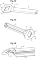
- THE figures 12 to 14 illustrate a variant of the first embodiment, in which the wiper blade 20 differs, the shaft 1 remaining identical.
- the mount 27 of the wiping blade 20 has a connection device 22 identical to that of the embodiment described above, but includes a different blade 28, for receiving a wiping element 21.
- the single blade 28 has a gutter profile, open on the side facing the surface to be wiped. This shape allows the blade 28 to have two lower holding claws. This profile allows the insertion and translation of a wiping element 21, the base of which has a corresponding capital I section (with two rods perpendicular to the two ends of the I).
- such a wiper blade has a narrower width than that of the wiper blade described previously, which reduces the disruption to the operation of the element to be wiped, for example a camera of a motor vehicle.
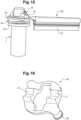
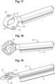
- THE figures 15 to 22 illustrate a second embodiment of the invention, which mainly differs from the first embodiment in that it comprises an anti-rotation collar 16, positioned between the wiper blade 20 and the pin 13, thus fulfilling the anti-rotation function -rotation.
- This solution makes it possible to simplify the geometry of shaft 1, as will be described below.
- the wiping blade 20 first comprises a frame 27 and a wiping element 21 identical to those of the variant of the first embodiment.
- the anti-rotation collar 16, more particularly visible on the Figure 16 is intended for mounting on the wiper blade 20, as shown on the figures 18 and 19 . It comprises two housings 17, of V-shaped section, aligned, of shape adapted to cooperate with the two ends of the pin 13, as is visible on the figures 15 , 21 and 22 . It further comprises two extensions 19 forming connection elements for its mounting on a wiper blade 20.
- the anti-rotation collar 16 is fixed at the level of the connection device 22 of the mount 27 of the wiper blade.
- the connection device 22 comprises two lateral openings 25 which come opposite the extensions 19 of the anti-rotation collar 16, thus making it possible to fix the latter either by clipping, or by screwing, or by any other mechanical solution or by gluing.
- the anti-rotation collar 16 comprises a central opening of shape identical to that of the opening of the connection device 22 of the frame, or of larger surface area, which superimposes with this opening of the connection device 22.
- the anti-rotation collar 16 the shaft 1 of the wiping system, particularly visible on the Figure 20 , has a simplified shape compared to that of shaft 1 of the first embodiment.
- the first three portions of this shaft 1 are replaced by a single cylindrical portion 6, comprising the cylindrical opening 3 for receiving a pin 13.
- the same elastic means in particular the three washers 14, 15, 14 mentioned above, can be positioned around the shaft 1 as in the first embodiment.
- connection device 22 of the wiper blade 20 is similarly simplified. It no longer includes the protuberances 24 since the shaft 1 no longer includes splines 4. It includes a substantially circular central part, of diameter slightly greater than that of the cylindrical portion 6 of the shaft 1, and two enlarged portions 23, of shape corresponding to that of the pin 13.
- the wiper blade is thus mounted on the shaft, then turned a quarter turn so as to position the housings 17 of the anti-rotation collar 16 under the ends of the pin 13.
- these housings 17 cooperate with the pin 13, this arrangement being held firmly under the effect of the elastic hub 15. By this means, the wiper blade cannot escape to shaft 1, nor turn around this shaft 1.
- the figures 21 and 22 illustrate more precisely the relative positioning of the anti-rotation collar 16 and the shaft 1, in particular the pin 13. It thus appears that the anti-rotation collar participates not only in the aforementioned anti-rotation function, but also in the function locking the wiper blade 20 in operating configuration.
- the anti-rotation collar 16 could not be a separate element, but come from the same part with all or part of the wiping blade, as will be the case in the embodiment represented by the Figure 28 .
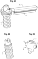
- this third embodiment differs from the two previous ones in that the shaft 1 is in the form of two distinct main components fixed to each other.
- the bottom axis 7 is simplified, perforated, as represented by the Figure 24 .
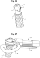
- the high axis 6, represented by the Figure 25 includes connectors allowing it to cooperate with the bottom axis 7, for fixing for example by welding, to form a resulting shaft 1, shown on the Figure 26 , of overall shape similar to the tree of the second embodiment.
- the pin 13 is no longer an independent element but can form the same part with the high axis. Indeed, it is thus possible to mount the elastic means, in particular the three washers 14, 15, 14 mentioned above on the lower axis 7, before fixing the upper axis 6, thus securing the elastic means and finalizing the tree 1.
- THE figures 27 to 35 illustrate a variant of the third embodiment, in which the wiping blade integrates a device for dispensing a cleaning liquid.
- the wiping system includes a pipe 30 for supplying the wiping blade 20 with cleaning liquid.
- THE figures 28 to 31 thus illustrate the mount 27 of the wiper blade 20. It comprises a first end piece 32 comprising the connection device 22 for the shaft 1, then a cleaning liquid inlet portion, comprising an inlet connector 33, then an outlet 35 allowing the direction of the cleaning liquid towards the wiping element 21, then the surface to be wiped.
- Two parallel 28 blades can be fixed in this first tip 32.
- a second tip 34 is positioned at the opposite end of said two blades 28, to form the frame 27 visible on the figures 29 and 31 .
- a wiping element 21 is then fixed to this mount 27, to form the wiping blade 20 shown in Figure 32 .
- a curved pipe 30, to match the shape of the shaft 1, shown on the Figure 33 comprises one end fixed to the inlet connector 33, then a second end 31 intended for connection with a cleaning liquid supply device, not shown.
- the shaft 1 comprises lugs 8 at its second end 9, for clipping the pipe 30 at its second end 31, where it takes a rectilinear shape parallel to the shaft 1, to minimize the increased overall size through pipe 30.
- the frame 27 can be made of metal, or even rigid plastic.
- the wiping element 21 is preferably made of rubber, in a known manner.
- the collar can be plastic or metal.
- Shaft 1 is preferably made of metal.
- any other elastic means could be used, comprising for example at least one spring, in particular helical or leaf spring.
- the elastic means could be mounted on the wiper blade 20, at the level of its connection device 22, and not on the shaft.
- the drive shaft 1 and the wiper blade 20 can take different shapes.
- the pin of the shaft 1 could take any other shape allowing it to form a stop for the wiper blade 20 in operating configuration.
- the pin forms two symmetrically opposed stops around the axis of the shaft, to ensure the stability of the operating configuration.
- the shaft could alternatively comprise more than two stops, for example three or four stops, distributed around its axis.
- the shaft advantageously has symmetry around its axis, which also represents its axis of rotation.
- the anti-rotation device can also take any form other than those shown: it comprises complementary anti-rotation means arranged on the drive shaft 1 and on the wiper blade 20.
- the anti-rotation device can be independent of the broom locking means or confused with it.
- the first embodiment uses splines distributed regularly around the shaft. Alternatively, any notch machined into the shaft could be used.
- connection of the drive shaft 1 and the wiper blade 20 can also be different, since it allows their removable assembly involving a simple relative rotation, and bringing into play an anti-rotation device and a device for locking, with the participation of an elastic means.
- the wiper blade thus comprises a female connection device, and the shaft 1 a complementary male connection device. These female/male parts could be reversed.
- the wiper blade 20, or more simply a sub-part such as a mount 27, or even a sub-part 32 of the mount 27, comprises a connection device 22 capable of a removable connection with a shaft 1 driving the wiper blade 20, this connection device 22 comprising a first orientation which allows assembly/disassembly relative to a drive shaft 1, and a second orientation which does not allow this assembly/disassembly.
- the invention is particularly suitable for wiping small active surfaces of cameras or lighting devices, in particular for motor vehicle. However, it remains compatible with any other application requiring cleaning of a surface.
Landscapes
- Engineering & Computer Science (AREA)
- Mechanical Engineering (AREA)
- Pivots And Pivotal Connections (AREA)
- Ink Jet (AREA)
- Cleaning In General (AREA)
- Water Supply & Treatment (AREA)
- Pens And Brushes (AREA)
- Studio Devices (AREA)
Claims (12)
- Wischerblatt (20) für ein Wischersystem, insbesondere zum Wischen einer Kamera eines Kraftfahrzeugs, welches eine Verbindungsvorrichtung (22) umfasst, die für eine lösbare Verbindung mit einer Antriebswelle (1) des Wischerblatts (20) geeignet ist, wobei diese Verbindungsvorrichtung (22) eine erste Ausrichtung, welche die Montage/Demontage bezüglich einer Antriebswelle (1) ermöglicht, und eine zweite Ausrichtung, welche diese Montage/Demontage nicht ermöglicht, aufweist, dadurch gekennzeichnet, dass die Verbindungsvorrichtung (22) eine Öffnung an einem Ende des Wischerblatts (20) umfasst, die mindestens zwei verbreiterte Abschnitte (23) für ihre Montage und Demontage umfasst.
- Wischerblatt (20) für ein Wischersystem nach einem der vorhergehenden Ansprüche, dadurch gekennzeichnet, dass es ein Verdrehsicherungsmittel umfasst, insbesondere durch mindestens einen Vorsprung (24) an einer Öffnung seiner Verbindungsvorrichtung (22) oder durch einen Flansch (16), der mindestens eine Aufnahme (19) zum Zusammenwirken mit mindestens einem Anschlag einer Antriebswelle (1) umfasst.
- Wischerblatt (20) für ein Wischersystem nach einem der vorhergehenden Ansprüche, dadurch gekennzeichnet, dass es eine Halterung (27) umfasst, die Gleitführungen zur lösbaren Befestigung eines Wischelements (21) durch Verschiebung bildet, das dazu bestimmt ist, mit der zu wischenden Fläche in Kontakt zu kommen.
- Wischersystem, dadurch gekennzeichnet, dass es eine Antriebswelle (1) und ein Wischerblatt (20) nach einem der vorhergehenden Ansprüche, das lösbar an dieser Antriebswelle (1) befestigt ist, umfasst.
- Wischersystem nach dem vorhergehenden Anspruch, dadurch gekennzeichnet, dass es eine Betriebskonfiguration aufweist, in der ein elastisches Mittel (15) eine Kraft auf das Wischerblatt (20) ausübt, die bestrebt ist, es an mindestens einem Anschlag der Antriebswelle (1), insbesondere einem Zapfen (13), in Anlage zu halten, um das Wischerblatt (20) in dieser Betriebskonfiguration zu verriegeln.
- Wischersystem nach einem der Ansprüche 4 oder 5, dadurch gekennzeichnet, dass das Wischerblatt (20) und die Antriebswelle (1) jeweilige Verbindungsvorrichtungen (22, 2) umfassen, die dafür ausgelegt sind, ihre Montage und/oder Demontage durch ihre Betätigung nacheinander gemäß einer ersten relativen Translationsbewegung parallel zur Achse der Antriebswelle (1) und danach gemäß einer zweiten relativen Rotationsbewegung um die Achse der Antriebswelle (1) zu ermöglichen.
- Wischersystem nach einem der Ansprüche 5 oder 6, dadurch gekennzeichnet, dass das Wischerblatt (20) und die Antriebswelle (1) jeweilige Verdrehsicherungsmittel umfassen, die dafür ausgelegt sind, eine Verdrehsicherungsvorrichtung des Wischerblatts (20) in Bezug auf die Antriebswelle (1) in der Betriebskonfiguration zu bilden.
- Wischersystem nach dem vorhergehenden Anspruch, dadurch gekennzeichnet, dass die Antriebswelle (1) einen ersten Abschnitt mit Längsnuten (4) umfasst, die ein Verdrehsicherungsmittel bilden, und dadurch, dass das Wischerblatt eine Öffnung mit Vorsprüngen (24) mit einem den Längsnuten entsprechenden Format umfasst, die dafür ausgelegt sind, in der Betriebskonfiguration des Wischersystems in den Längsnuten (4) aufgenommen zu werden und eine Verdrehsicherungsvorrichtung zu bilden.
- Wischersystem nach Anspruch 7, dadurch gekennzeichnet, dass die Antriebswelle (1) einen Zapfen (13) umfasst, der ein Verdrehsicherungsmittel und einen Verriegelungsanschlag bildet, und dadurch, dass das Wischerblatt (20) einen Verdrehsicherungsflansch (16) umfasst, der Aufnahmen (19) umfasst, die dafür ausgelegt sind, in der Betriebskonfiguration des Wischersystems mit dem Zapfen (13) zusammenzuwirken, und der somit ein Verdrehsicherungsmittel und ein Verriegelungsmittel des Wischerblatts (20) auf der Antriebswelle (1) bildet.
- Wischersystem nach einem der Ansprüche 5 bis 9, dadurch gekennzeichnet, dass das elastische Mittel eine Federscheibe (15) umfasst, die insbesondere zwischen zwei Unterlegscheiben (14) angeordnet ist.
- Kamera oder Beleuchtungsvorrichtung für ein Kraftfahrzeug, dadurch gekennzeichnet, dass sie mindestens ein Wischersystem nach einem der Ansprüche 4 bis 10 umfasst.
- Kraftfahrzeug, vorzugsweise autonomes Kraftfahrzeug, dadurch gekennzeichnet, dass es mindestens ein Wischersystem nach einem der Ansprüche 4 bis 10 oder eine Kamera oder eine Beleuchtungsvorrichtung nach Anspruch 11 umfasst.
Applications Claiming Priority (2)
| Application Number | Priority Date | Filing Date | Title |
|---|---|---|---|
| FR2000820A FR3106548B1 (fr) | 2020-01-28 | 2020-01-28 | Essuyage pour petite surface |
| PCT/EP2021/050412 WO2021151646A1 (fr) | 2020-01-28 | 2021-01-11 | Essuyage pour petite surface |
Publications (2)
| Publication Number | Publication Date |
|---|---|
| EP4096972A1 EP4096972A1 (de) | 2022-12-07 |
| EP4096972B1 true EP4096972B1 (de) | 2024-03-20 |
Family
ID=70154711
Family Applications (1)
| Application Number | Title | Priority Date | Filing Date |
|---|---|---|---|
| EP21700295.5A Active EP4096972B1 (de) | 2020-01-28 | 2021-01-11 | Kleinflächiges wischen |
Country Status (8)
| Country | Link |
|---|---|
| US (1) | US20230055368A1 (de) |
| EP (1) | EP4096972B1 (de) |
| JP (1) | JP7631355B2 (de) |
| KR (1) | KR20220127270A (de) |
| CN (1) | CN115038621A (de) |
| DE (1) | DE112021000750T5 (de) |
| FR (1) | FR3106548B1 (de) |
| WO (1) | WO2021151646A1 (de) |
Families Citing this family (1)
| Publication number | Priority date | Publication date | Assignee | Title |
|---|---|---|---|---|
| DE102024102034A1 (de) * | 2024-01-24 | 2025-07-24 | Bayerische Motoren Werke Aktiengesellschaft | Scheibenwischer für ein kraftfahrzeug |
Family Cites Families (26)
| Publication number | Priority date | Publication date | Assignee | Title |
|---|---|---|---|---|
| US381915A (en) * | 1888-05-01 | Haeey e | ||
| US2964775A (en) * | 1953-01-02 | 1960-12-20 | Anderson Co | Means for attaching a wiper arm to a shaft |
| US3041093A (en) * | 1960-01-08 | 1962-06-26 | Gen Motors Corp | Windshield wiper arm attachment |
| US2994900A (en) * | 1960-07-01 | 1961-08-08 | Trico Products Corp | Windscreen wipers |
| US3247541A (en) * | 1963-08-31 | 1966-04-26 | Rau Swf Autozubehoer | Windshield wiper |
| US3512205A (en) * | 1968-07-05 | 1970-05-19 | Trico Products Corp | Windshield wiper arm |
| DE7037380U (de) * | 1970-10-09 | 1972-03-23 | Bosch R Gmbh | Scheibenwischerarm fuer kraftfahrzeuge |
| US3716888A (en) * | 1971-08-26 | 1973-02-20 | Trico Products Corp | Windshield wiper arm |
| JPS513552Y2 (de) * | 1971-10-04 | 1976-02-02 | ||
| US4266883A (en) * | 1979-04-16 | 1981-05-12 | Trico Products Corporation | Windshield wiper linkage |
| US4566146A (en) * | 1984-04-30 | 1986-01-28 | The Anderson Company Of Indiana | Retainer clip for a wiper arm |
| JPH061817B2 (ja) * | 1986-11-20 | 1994-01-05 | 富士電機株式会社 | 相補型電界効果トランジスタ |
| JPS63129658U (de) * | 1987-02-17 | 1988-08-24 | ||
| JPH02227353A (ja) * | 1989-02-28 | 1990-09-10 | Mitsubishi Electric Corp | 車輌塔載距離測定装置 |
| FR2827203B1 (fr) * | 2001-07-12 | 2003-10-03 | Toolmatic Bvba | Tete d'aspiration, couronne et rallonge pour forage a sec |
| DE10259479A1 (de) * | 2002-12-19 | 2004-07-01 | Robert Bosch Gmbh | Wischhebel |
| KR100537950B1 (ko) * | 2003-12-06 | 2005-12-20 | 동양기전 주식회사 | 와이퍼 조립체 |
| JP2007053448A (ja) * | 2005-08-15 | 2007-03-01 | Fujifilm Corp | 撮影装置 |
| US8392633B2 (en) * | 2008-06-25 | 2013-03-05 | Hewlett-Packard Development Company, L.P. | Scheduling requesters of a shared storage resource |
| DE102012201063A1 (de) * | 2012-01-25 | 2013-07-25 | Robert Bosch Gmbh | Wischvorrichtung |
| DE102013222993A1 (de) * | 2013-11-12 | 2015-05-28 | Robert Bosch Gmbh | Scheibenwischvorrichtung |
| DE102014110064A1 (de) * | 2014-07-17 | 2016-01-21 | Valeo Systèmes d'Essuyage | Wischvorrichtung zum Reinigen einer Fahrzeugscheibe und Wischblatt für eine Wischvorrichtung |
| DE102014215686A1 (de) * | 2014-08-07 | 2016-02-11 | Robert Bosch Gmbh | Finray-Wischer mit Klemmvorrichtung |
| US9731688B2 (en) * | 2014-10-31 | 2017-08-15 | Waymo Llc | Passive wiper system |
| FR3050158B1 (fr) * | 2016-04-13 | 2019-08-09 | Valeo Systemes D'essuyage | Systeme d’essuyage d’un pare-brise de vehicule |
| CN207790628U (zh) * | 2018-01-25 | 2018-08-31 | 北京图森未来科技有限公司 | 一种无人驾驶车辆及其传感器装置和清洁机构 |
-
2020
- 2020-01-28 FR FR2000820A patent/FR3106548B1/fr not_active Expired - Fee Related
-
2021
- 2021-01-11 CN CN202180011595.9A patent/CN115038621A/zh active Pending
- 2021-01-11 KR KR1020227026206A patent/KR20220127270A/ko not_active Withdrawn
- 2021-01-11 DE DE112021000750.5T patent/DE112021000750T5/de active Pending
- 2021-01-11 JP JP2022545866A patent/JP7631355B2/ja active Active
- 2021-01-11 EP EP21700295.5A patent/EP4096972B1/de active Active
- 2021-01-11 US US17/795,694 patent/US20230055368A1/en not_active Abandoned
- 2021-01-11 WO PCT/EP2021/050412 patent/WO2021151646A1/fr not_active Ceased
Also Published As
| Publication number | Publication date |
|---|---|
| JP2023512016A (ja) | 2023-03-23 |
| DE112021000750T5 (de) | 2022-11-10 |
| JP7631355B2 (ja) | 2025-02-18 |
| FR3106548A1 (fr) | 2021-07-30 |
| FR3106548B1 (fr) | 2022-10-28 |
| KR20220127270A (ko) | 2022-09-19 |
| WO2021151646A1 (fr) | 2021-08-05 |
| US20230055368A1 (en) | 2023-02-23 |
| CN115038621A (zh) | 2022-09-09 |
| EP4096972A1 (de) | 2022-12-07 |
Similar Documents
| Publication | Publication Date | Title |
|---|---|---|
| EP2027000B1 (de) | Vorrichtung zur befestigung eines scheibenwischerblattes an einem arm | |
| EP1833708A1 (de) | Anpassbarer windschutzscheiben-flachwischer und zugehöriges lösbares verbindungsteil | |
| FR3066457A1 (fr) | Adaptateur destine a relier un balai d'essuyage a un bras d'entrainement d'un systeme d'essuyage | |
| FR2979876A1 (fr) | Ensemble de connexion pour systeme d'essuyage d'un vehicule automobile | |
| EP4096972B1 (de) | Kleinflächiges wischen | |
| FR3059961B1 (fr) | Adaptateur pour balai d'essuie glace | |
| EP2965957B1 (de) | Schwenkbares verbindungselement für ein scheibenwischerblatt eines fahrzeugs | |
| EP3081442B1 (de) | Scheibenwischer und wischereinheit, die einen solchen scheibenwischer umfasst | |
| FR3100504A1 (fr) | Maneton, boîte à rotule et système de tringlerie d’actionnement d’essuie-glaces correspondant et son procédé d’assemblage | |
| EP4144599A1 (de) | Adapter für reinigungssystem | |
| EP4214097A1 (de) | Adapter für eine kraftfahrzeugwischeranlage | |
| EP3375675B1 (de) | Abdeckung, verbindungsvorrichtung für die montage eines scheibenwischerblatts auf einem entsprechenden scheibenwischerarm, und entsprechendes scheibenwischsystem | |
| EP3604051A1 (de) | Einheit zum verbinden eines antriebsarms eines scheibenwischers mit einer motorwelle eines fahrzeugs | |
| FR2732083A1 (fr) | Dispositif de connexion a montage simplifie pour assembler deux profiles | |
| WO2024184338A1 (fr) | Adaptateur pour l'assemblage d'un balai à un bras d'essuie-glace | |
| WO2025146496A1 (fr) | Adaptateur pour l'assemblage d'un balai à un bras d'essuie-glace | |
| WO2025146493A1 (fr) | Adaptateur pour l'assemblage d'un balai à un bras d'essuie-glace | |
| WO2023208726A1 (fr) | Ensemble de connexion d'un système d'essuyage | |
| EP4124518A1 (de) | Verbindungsvorrichtung zwischen wischblatt und antriebsarm | |
| WO2025146495A1 (fr) | Adaptateur pour l'assemblage d'un balai à un bras d'essuie-glace | |
| WO2018050326A1 (fr) | Adaptateur pour la connexion d'un balai d'essuyage a un bras d'entrainement d'un systeme d'essuyage pour vehicule automobile | |
| WO2022058349A1 (fr) | Systeme d'essuyage pour vehicule automobile | |
| FR3152139A1 (fr) | Adaptateur pour l’assemblage d’un balai à un bras d’essuie-glace | |
| FR3143494A1 (fr) | Adaptateur d’un système d’essuyage | |
| FR2903466A1 (fr) | Systeme d'ecrou flottant |
Legal Events
| Date | Code | Title | Description |
|---|---|---|---|
| STAA | Information on the status of an ep patent application or granted ep patent |
Free format text: STATUS: UNKNOWN |
|
| STAA | Information on the status of an ep patent application or granted ep patent |
Free format text: STATUS: THE INTERNATIONAL PUBLICATION HAS BEEN MADE |
|
| PUAI | Public reference made under article 153(3) epc to a published international application that has entered the european phase |
Free format text: ORIGINAL CODE: 0009012 |
|
| STAA | Information on the status of an ep patent application or granted ep patent |
Free format text: STATUS: REQUEST FOR EXAMINATION WAS MADE |
|
| 17P | Request for examination filed |
Effective date: 20220705 |
|
| AK | Designated contracting states |
Kind code of ref document: A1 Designated state(s): AL AT BE BG CH CY CZ DE DK EE ES FI FR GB GR HR HU IE IS IT LI LT LU LV MC MK MT NL NO PL PT RO RS SE SI SK SM TR |
|
| DAV | Request for validation of the european patent (deleted) | ||
| DAX | Request for extension of the european patent (deleted) | ||
| GRAP | Despatch of communication of intention to grant a patent |
Free format text: ORIGINAL CODE: EPIDOSNIGR1 |
|
| STAA | Information on the status of an ep patent application or granted ep patent |
Free format text: STATUS: GRANT OF PATENT IS INTENDED |
|
| INTG | Intention to grant announced |
Effective date: 20231218 |
|
| GRAS | Grant fee paid |
Free format text: ORIGINAL CODE: EPIDOSNIGR3 |
|
| GRAA | (expected) grant |
Free format text: ORIGINAL CODE: 0009210 |
|
| STAA | Information on the status of an ep patent application or granted ep patent |
Free format text: STATUS: THE PATENT HAS BEEN GRANTED |
|
| AK | Designated contracting states |
Kind code of ref document: B1 Designated state(s): AL AT BE BG CH CY CZ DE DK EE ES FI FR GB GR HR HU IE IS IT LI LT LU LV MC MK MT NL NO PL PT RO RS SE SI SK SM TR |
|
| REG | Reference to a national code |
Ref country code: GB Ref legal event code: FG4D Free format text: NOT ENGLISH |
|
| REG | Reference to a national code |
Ref country code: CH Ref legal event code: EP |
|
| REG | Reference to a national code |
Ref country code: DE Ref legal event code: R096 Ref document number: 602021010648 Country of ref document: DE |
|
| REG | Reference to a national code |
Ref country code: IE Ref legal event code: FG4D Free format text: LANGUAGE OF EP DOCUMENT: FRENCH |
|
| PG25 | Lapsed in a contracting state [announced via postgrant information from national office to epo] |
Ref country code: LT Free format text: LAPSE BECAUSE OF FAILURE TO SUBMIT A TRANSLATION OF THE DESCRIPTION OR TO PAY THE FEE WITHIN THE PRESCRIBED TIME-LIMIT Effective date: 20240320 |
|
| REG | Reference to a national code |
Ref country code: LT Ref legal event code: MG9D |
|
| PG25 | Lapsed in a contracting state [announced via postgrant information from national office to epo] |
Ref country code: GR Free format text: LAPSE BECAUSE OF FAILURE TO SUBMIT A TRANSLATION OF THE DESCRIPTION OR TO PAY THE FEE WITHIN THE PRESCRIBED TIME-LIMIT Effective date: 20240621 |
|
| PG25 | Lapsed in a contracting state [announced via postgrant information from national office to epo] |
Ref country code: RS Free format text: LAPSE BECAUSE OF FAILURE TO SUBMIT A TRANSLATION OF THE DESCRIPTION OR TO PAY THE FEE WITHIN THE PRESCRIBED TIME-LIMIT Effective date: 20240620 Ref country code: HR Free format text: LAPSE BECAUSE OF FAILURE TO SUBMIT A TRANSLATION OF THE DESCRIPTION OR TO PAY THE FEE WITHIN THE PRESCRIBED TIME-LIMIT Effective date: 20240320 |
|
| REG | Reference to a national code |
Ref country code: NL Ref legal event code: MP Effective date: 20240320 |
|
| PG25 | Lapsed in a contracting state [announced via postgrant information from national office to epo] |
Ref country code: RS Free format text: LAPSE BECAUSE OF FAILURE TO SUBMIT A TRANSLATION OF THE DESCRIPTION OR TO PAY THE FEE WITHIN THE PRESCRIBED TIME-LIMIT Effective date: 20240620 Ref country code: NO Free format text: LAPSE BECAUSE OF FAILURE TO SUBMIT A TRANSLATION OF THE DESCRIPTION OR TO PAY THE FEE WITHIN THE PRESCRIBED TIME-LIMIT Effective date: 20240620 Ref country code: LT Free format text: LAPSE BECAUSE OF FAILURE TO SUBMIT A TRANSLATION OF THE DESCRIPTION OR TO PAY THE FEE WITHIN THE PRESCRIBED TIME-LIMIT Effective date: 20240320 Ref country code: HR Free format text: LAPSE BECAUSE OF FAILURE TO SUBMIT A TRANSLATION OF THE DESCRIPTION OR TO PAY THE FEE WITHIN THE PRESCRIBED TIME-LIMIT Effective date: 20240320 Ref country code: GR Free format text: LAPSE BECAUSE OF FAILURE TO SUBMIT A TRANSLATION OF THE DESCRIPTION OR TO PAY THE FEE WITHIN THE PRESCRIBED TIME-LIMIT Effective date: 20240621 Ref country code: FI Free format text: LAPSE BECAUSE OF FAILURE TO SUBMIT A TRANSLATION OF THE DESCRIPTION OR TO PAY THE FEE WITHIN THE PRESCRIBED TIME-LIMIT Effective date: 20240320 Ref country code: BG Free format text: LAPSE BECAUSE OF FAILURE TO SUBMIT A TRANSLATION OF THE DESCRIPTION OR TO PAY THE FEE WITHIN THE PRESCRIBED TIME-LIMIT Effective date: 20240320 |
|
| REG | Reference to a national code |
Ref country code: AT Ref legal event code: MK05 Ref document number: 1667567 Country of ref document: AT Kind code of ref document: T Effective date: 20240320 |
|
| PG25 | Lapsed in a contracting state [announced via postgrant information from national office to epo] |
Ref country code: SE Free format text: LAPSE BECAUSE OF FAILURE TO SUBMIT A TRANSLATION OF THE DESCRIPTION OR TO PAY THE FEE WITHIN THE PRESCRIBED TIME-LIMIT Effective date: 20240320 Ref country code: LV Free format text: LAPSE BECAUSE OF FAILURE TO SUBMIT A TRANSLATION OF THE DESCRIPTION OR TO PAY THE FEE WITHIN THE PRESCRIBED TIME-LIMIT Effective date: 20240320 |
|
| PG25 | Lapsed in a contracting state [announced via postgrant information from national office to epo] |
Ref country code: NL Free format text: LAPSE BECAUSE OF FAILURE TO SUBMIT A TRANSLATION OF THE DESCRIPTION OR TO PAY THE FEE WITHIN THE PRESCRIBED TIME-LIMIT Effective date: 20240320 |
|
| PG25 | Lapsed in a contracting state [announced via postgrant information from national office to epo] |
Ref country code: NL Free format text: LAPSE BECAUSE OF FAILURE TO SUBMIT A TRANSLATION OF THE DESCRIPTION OR TO PAY THE FEE WITHIN THE PRESCRIBED TIME-LIMIT Effective date: 20240320 |
|
| PG25 | Lapsed in a contracting state [announced via postgrant information from national office to epo] |
Ref country code: IS Free format text: LAPSE BECAUSE OF FAILURE TO SUBMIT A TRANSLATION OF THE DESCRIPTION OR TO PAY THE FEE WITHIN THE PRESCRIBED TIME-LIMIT Effective date: 20240720 |
|
| PG25 | Lapsed in a contracting state [announced via postgrant information from national office to epo] |
Ref country code: PT Free format text: LAPSE BECAUSE OF FAILURE TO SUBMIT A TRANSLATION OF THE DESCRIPTION OR TO PAY THE FEE WITHIN THE PRESCRIBED TIME-LIMIT Effective date: 20240722 Ref country code: SM Free format text: LAPSE BECAUSE OF FAILURE TO SUBMIT A TRANSLATION OF THE DESCRIPTION OR TO PAY THE FEE WITHIN THE PRESCRIBED TIME-LIMIT Effective date: 20240320 |
|
| PG25 | Lapsed in a contracting state [announced via postgrant information from national office to epo] |
Ref country code: ES Free format text: LAPSE BECAUSE OF FAILURE TO SUBMIT A TRANSLATION OF THE DESCRIPTION OR TO PAY THE FEE WITHIN THE PRESCRIBED TIME-LIMIT Effective date: 20240320 |
|
| PG25 | Lapsed in a contracting state [announced via postgrant information from national office to epo] |
Ref country code: CZ Free format text: LAPSE BECAUSE OF FAILURE TO SUBMIT A TRANSLATION OF THE DESCRIPTION OR TO PAY THE FEE WITHIN THE PRESCRIBED TIME-LIMIT Effective date: 20240320 Ref country code: EE Free format text: LAPSE BECAUSE OF FAILURE TO SUBMIT A TRANSLATION OF THE DESCRIPTION OR TO PAY THE FEE WITHIN THE PRESCRIBED TIME-LIMIT Effective date: 20240320 |
|
| PG25 | Lapsed in a contracting state [announced via postgrant information from national office to epo] |
Ref country code: AT Free format text: LAPSE BECAUSE OF FAILURE TO SUBMIT A TRANSLATION OF THE DESCRIPTION OR TO PAY THE FEE WITHIN THE PRESCRIBED TIME-LIMIT Effective date: 20240320 |
|
| PG25 | Lapsed in a contracting state [announced via postgrant information from national office to epo] |
Ref country code: PL Free format text: LAPSE BECAUSE OF FAILURE TO SUBMIT A TRANSLATION OF THE DESCRIPTION OR TO PAY THE FEE WITHIN THE PRESCRIBED TIME-LIMIT Effective date: 20240320 |
|
| PG25 | Lapsed in a contracting state [announced via postgrant information from national office to epo] |
Ref country code: SK Free format text: LAPSE BECAUSE OF FAILURE TO SUBMIT A TRANSLATION OF THE DESCRIPTION OR TO PAY THE FEE WITHIN THE PRESCRIBED TIME-LIMIT Effective date: 20240320 |
|
| PG25 | Lapsed in a contracting state [announced via postgrant information from national office to epo] |
Ref country code: SM Free format text: LAPSE BECAUSE OF FAILURE TO SUBMIT A TRANSLATION OF THE DESCRIPTION OR TO PAY THE FEE WITHIN THE PRESCRIBED TIME-LIMIT Effective date: 20240320 Ref country code: SK Free format text: LAPSE BECAUSE OF FAILURE TO SUBMIT A TRANSLATION OF THE DESCRIPTION OR TO PAY THE FEE WITHIN THE PRESCRIBED TIME-LIMIT Effective date: 20240320 Ref country code: RO Free format text: LAPSE BECAUSE OF FAILURE TO SUBMIT A TRANSLATION OF THE DESCRIPTION OR TO PAY THE FEE WITHIN THE PRESCRIBED TIME-LIMIT Effective date: 20240320 Ref country code: PT Free format text: LAPSE BECAUSE OF FAILURE TO SUBMIT A TRANSLATION OF THE DESCRIPTION OR TO PAY THE FEE WITHIN THE PRESCRIBED TIME-LIMIT Effective date: 20240722 Ref country code: PL Free format text: LAPSE BECAUSE OF FAILURE TO SUBMIT A TRANSLATION OF THE DESCRIPTION OR TO PAY THE FEE WITHIN THE PRESCRIBED TIME-LIMIT Effective date: 20240320 Ref country code: IS Free format text: LAPSE BECAUSE OF FAILURE TO SUBMIT A TRANSLATION OF THE DESCRIPTION OR TO PAY THE FEE WITHIN THE PRESCRIBED TIME-LIMIT Effective date: 20240720 Ref country code: ES Free format text: LAPSE BECAUSE OF FAILURE TO SUBMIT A TRANSLATION OF THE DESCRIPTION OR TO PAY THE FEE WITHIN THE PRESCRIBED TIME-LIMIT Effective date: 20240320 Ref country code: EE Free format text: LAPSE BECAUSE OF FAILURE TO SUBMIT A TRANSLATION OF THE DESCRIPTION OR TO PAY THE FEE WITHIN THE PRESCRIBED TIME-LIMIT Effective date: 20240320 Ref country code: CZ Free format text: LAPSE BECAUSE OF FAILURE TO SUBMIT A TRANSLATION OF THE DESCRIPTION OR TO PAY THE FEE WITHIN THE PRESCRIBED TIME-LIMIT Effective date: 20240320 Ref country code: AT Free format text: LAPSE BECAUSE OF FAILURE TO SUBMIT A TRANSLATION OF THE DESCRIPTION OR TO PAY THE FEE WITHIN THE PRESCRIBED TIME-LIMIT Effective date: 20240320 |
|
| PG25 | Lapsed in a contracting state [announced via postgrant information from national office to epo] |
Ref country code: IT Free format text: LAPSE BECAUSE OF FAILURE TO SUBMIT A TRANSLATION OF THE DESCRIPTION OR TO PAY THE FEE WITHIN THE PRESCRIBED TIME-LIMIT Effective date: 20240320 |
|
| REG | Reference to a national code |
Ref country code: DE Ref legal event code: R097 Ref document number: 602021010648 Country of ref document: DE |
|
| PG25 | Lapsed in a contracting state [announced via postgrant information from national office to epo] |
Ref country code: IT Free format text: LAPSE BECAUSE OF FAILURE TO SUBMIT A TRANSLATION OF THE DESCRIPTION OR TO PAY THE FEE WITHIN THE PRESCRIBED TIME-LIMIT Effective date: 20240320 |
|
| PG25 | Lapsed in a contracting state [announced via postgrant information from national office to epo] |
Ref country code: DK Free format text: LAPSE BECAUSE OF FAILURE TO SUBMIT A TRANSLATION OF THE DESCRIPTION OR TO PAY THE FEE WITHIN THE PRESCRIBED TIME-LIMIT Effective date: 20240320 |
|
| PLBE | No opposition filed within time limit |
Free format text: ORIGINAL CODE: 0009261 |
|
| STAA | Information on the status of an ep patent application or granted ep patent |
Free format text: STATUS: NO OPPOSITION FILED WITHIN TIME LIMIT |
|
| PG25 | Lapsed in a contracting state [announced via postgrant information from national office to epo] |
Ref country code: DK Free format text: LAPSE BECAUSE OF FAILURE TO SUBMIT A TRANSLATION OF THE DESCRIPTION OR TO PAY THE FEE WITHIN THE PRESCRIBED TIME-LIMIT Effective date: 20240320 |
|
| 26N | No opposition filed |
Effective date: 20241223 |
|
| PG25 | Lapsed in a contracting state [announced via postgrant information from national office to epo] |
Ref country code: SI Free format text: LAPSE BECAUSE OF FAILURE TO SUBMIT A TRANSLATION OF THE DESCRIPTION OR TO PAY THE FEE WITHIN THE PRESCRIBED TIME-LIMIT Effective date: 20240320 |
|
| REG | Reference to a national code |
Ref country code: CH Ref legal event code: PL |
|
| PG25 | Lapsed in a contracting state [announced via postgrant information from national office to epo] |
Ref country code: LU Free format text: LAPSE BECAUSE OF NON-PAYMENT OF DUE FEES Effective date: 20250111 Ref country code: MC Free format text: LAPSE BECAUSE OF FAILURE TO SUBMIT A TRANSLATION OF THE DESCRIPTION OR TO PAY THE FEE WITHIN THE PRESCRIBED TIME-LIMIT Effective date: 20240320 |
|
| GBPC | Gb: european patent ceased through non-payment of renewal fee |
Effective date: 20250111 |
|
| PG25 | Lapsed in a contracting state [announced via postgrant information from national office to epo] |
Ref country code: BE Free format text: LAPSE BECAUSE OF NON-PAYMENT OF DUE FEES Effective date: 20250131 Ref country code: GB Free format text: LAPSE BECAUSE OF NON-PAYMENT OF DUE FEES Effective date: 20250111 |
|
| PG25 | Lapsed in a contracting state [announced via postgrant information from national office to epo] |
Ref country code: CH Free format text: LAPSE BECAUSE OF NON-PAYMENT OF DUE FEES Effective date: 20250131 |
|
| REG | Reference to a national code |
Ref country code: BE Ref legal event code: MM Effective date: 20250131 |
|
| PG25 | Lapsed in a contracting state [announced via postgrant information from national office to epo] |
Ref country code: IE Free format text: LAPSE BECAUSE OF NON-PAYMENT OF DUE FEES Effective date: 20250111 |
|
| PGFP | Annual fee paid to national office [announced via postgrant information from national office to epo] |
Ref country code: DE Payment date: 20260114 Year of fee payment: 6 |
|
| PGFP | Annual fee paid to national office [announced via postgrant information from national office to epo] |
Ref country code: FR Payment date: 20260128 Year of fee payment: 6 |