EP4099466A2 - Sulfid-festelektrolyt und all-solid-state-batterie - Google Patents
Sulfid-festelektrolyt und all-solid-state-batterie Download PDFInfo
- Publication number
- EP4099466A2 EP4099466A2 EP22186534.8A EP22186534A EP4099466A2 EP 4099466 A2 EP4099466 A2 EP 4099466A2 EP 22186534 A EP22186534 A EP 22186534A EP 4099466 A2 EP4099466 A2 EP 4099466A2
- Authority
- EP
- European Patent Office
- Prior art keywords
- solid electrolyte
- sulfide solid
- sulfide
- crystalline structure
- examples
- Prior art date
- Legal status (The legal status is an assumption and is not a legal conclusion. Google has not performed a legal analysis and makes no representation as to the accuracy of the status listed.)
- Granted
Links
Images


Classifications
-
- H—ELECTRICITY
- H01—ELECTRIC ELEMENTS
- H01B—CABLES; CONDUCTORS; INSULATORS; SELECTION OF MATERIALS FOR THEIR CONDUCTIVE, INSULATING OR DIELECTRIC PROPERTIES
- H01B1/00—Conductors or conductive bodies characterised by the conductive materials; Selection of materials as conductors
- H01B1/06—Conductors or conductive bodies characterised by the conductive materials; Selection of materials as conductors mainly consisting of other non-metallic substances
- H01B1/10—Conductors or conductive bodies characterised by the conductive materials; Selection of materials as conductors mainly consisting of other non-metallic substances sulfides
-
- C—CHEMISTRY; METALLURGY
- C01—INORGANIC CHEMISTRY
- C01B—NON-METALLIC ELEMENTS; COMPOUNDS THEREOF; METALLOIDS OR COMPOUNDS THEREOF NOT COVERED BY SUBCLASS C01C
- C01B25/00—Phosphorus; Compounds thereof
- C01B25/14—Sulfur, selenium, or tellurium compounds of phosphorus
-
- H—ELECTRICITY
- H01—ELECTRIC ELEMENTS
- H01M—PROCESSES OR MEANS, e.g. BATTERIES, FOR THE DIRECT CONVERSION OF CHEMICAL ENERGY INTO ELECTRICAL ENERGY
- H01M10/00—Secondary cells; Manufacture thereof
- H01M10/05—Accumulators with non-aqueous electrolyte
- H01M10/052—Li-accumulators
- H01M10/0525—Rocking-chair batteries, i.e. batteries with lithium insertion or intercalation in both electrodes; Lithium-ion batteries
-
- H—ELECTRICITY
- H01—ELECTRIC ELEMENTS
- H01M—PROCESSES OR MEANS, e.g. BATTERIES, FOR THE DIRECT CONVERSION OF CHEMICAL ENERGY INTO ELECTRICAL ENERGY
- H01M10/00—Secondary cells; Manufacture thereof
- H01M10/05—Accumulators with non-aqueous electrolyte
- H01M10/056—Accumulators with non-aqueous electrolyte characterised by the materials used as electrolytes, e.g. mixed inorganic/organic electrolytes
- H01M10/0561—Accumulators with non-aqueous electrolyte characterised by the materials used as electrolytes, e.g. mixed inorganic/organic electrolytes the electrolyte being constituted of inorganic materials only
- H01M10/0562—Solid materials
-
- H—ELECTRICITY
- H01—ELECTRIC ELEMENTS
- H01M—PROCESSES OR MEANS, e.g. BATTERIES, FOR THE DIRECT CONVERSION OF CHEMICAL ENERGY INTO ELECTRICAL ENERGY
- H01M4/00—Electrodes
- H01M4/02—Electrodes composed of, or comprising, active material
- H01M4/13—Electrodes for accumulators with non-aqueous electrolyte, e.g. for lithium-accumulators; Processes of manufacture thereof
-
- H—ELECTRICITY
- H01—ELECTRIC ELEMENTS
- H01M—PROCESSES OR MEANS, e.g. BATTERIES, FOR THE DIRECT CONVERSION OF CHEMICAL ENERGY INTO ELECTRICAL ENERGY
- H01M4/00—Electrodes
- H01M4/02—Electrodes composed of, or comprising, active material
- H01M4/62—Selection of inactive substances as ingredients for active masses, e.g. binders, fillers
-
- C—CHEMISTRY; METALLURGY
- C01—INORGANIC CHEMISTRY
- C01P—INDEXING SCHEME RELATING TO STRUCTURAL AND PHYSICAL ASPECTS OF SOLID INORGANIC COMPOUNDS
- C01P2002/00—Crystal-structural characteristics
- C01P2002/70—Crystal-structural characteristics defined by measured X-ray, neutron or electron diffraction data
- C01P2002/74—Crystal-structural characteristics defined by measured X-ray, neutron or electron diffraction data by peak-intensities or a ratio thereof only
-
- H—ELECTRICITY
- H01—ELECTRIC ELEMENTS
- H01M—PROCESSES OR MEANS, e.g. BATTERIES, FOR THE DIRECT CONVERSION OF CHEMICAL ENERGY INTO ELECTRICAL ENERGY
- H01M4/00—Electrodes
- H01M4/02—Electrodes composed of, or comprising, active material
- H01M2004/026—Electrodes composed of, or comprising, active material characterised by the polarity
- H01M2004/027—Negative electrodes
-
- H—ELECTRICITY
- H01—ELECTRIC ELEMENTS
- H01M—PROCESSES OR MEANS, e.g. BATTERIES, FOR THE DIRECT CONVERSION OF CHEMICAL ENERGY INTO ELECTRICAL ENERGY
- H01M2300/00—Electrolytes
- H01M2300/0017—Non-aqueous electrolytes
- H01M2300/0065—Solid electrolytes
- H01M2300/0068—Solid electrolytes inorganic
-
- Y—GENERAL TAGGING OF NEW TECHNOLOGICAL DEVELOPMENTS; GENERAL TAGGING OF CROSS-SECTIONAL TECHNOLOGIES SPANNING OVER SEVERAL SECTIONS OF THE IPC; TECHNICAL SUBJECTS COVERED BY FORMER USPC CROSS-REFERENCE ART COLLECTIONS [XRACs] AND DIGESTS
- Y02—TECHNOLOGIES OR APPLICATIONS FOR MITIGATION OR ADAPTATION AGAINST CLIMATE CHANGE
- Y02E—REDUCTION OF GREENHOUSE GAS [GHG] EMISSIONS, RELATED TO ENERGY GENERATION, TRANSMISSION OR DISTRIBUTION
- Y02E60/00—Enabling technologies; Technologies with a potential or indirect contribution to GHG emissions mitigation
- Y02E60/10—Energy storage using batteries
Definitions
- the present invention relates to a method for producing a sulfide solid electrolyte, a sulfide solid electrolyte, an all-solid-state battery, and a method for selecting a raw material compound for use in producing a sulfide solid electrolyte.
- Nonaqueous electrolyte secondary batteries typified by lithium-ion nonaqueous electrolyte secondary batteries are, because of the high energy density, heavily used in electronic devices such as personal computers and communication terminals, and automobiles.
- the nonaqueous electrolyte secondary battery typically including an electrode assembly with a pair of electrically isolated electrodes and a nonaqueous electrolyte interposed between the electrodes is configured for charge-discharge through ion transfer between the both electrodes.
- Patent Document 1 mentions the production of a sulfide solid electrolyte that has a composition of 75Li 2 S-25P 2 S 5 -yLi 3 N with Li 2 S, P 2 S 5 , and Li 3 N as starting materials.
- Patent Document 2 mentions the production of a sulfide solid electrolyte with the use of a raw material composition composed of Li 2 S, P 2 S 5 , LiBr, LiI, and Li 3 N.
- Patent Document 1 mentions that the sulfide solid electrolyte contains N, thereby making it possible to improve the atmospheric stability (water resistance) of the sulfide solid electrolyte.
- the use of LisN as a raw material for the sulfide solid electrolyte has, however, the problem of N discharged to the outside of the system.
- Patent Document 2 mentions that a raw material composition containing Li 2 S, P 2 S 5 , LiI, and LiBr is made amorphous and then subjected to a heat treatment to precipitate a high Li-ion conductive phase.
- the excessively high heat treatment temperature has, however, the problem of precipitating a low Li-ion conductive phase.
- Patent Document 3 mentions that the addition of Li 3 N can increase the difference between the temperature at which a high Li-ion conductive phase is produced and the temperature at which a low Li-ion conductive phase is produced, but the difference is as small as approximately 30°C at a maximum, and further improvements have been required.
- the present invention has been made based on the above-described circumstances, and an object of an aspect of the present invention is to provide a method for producing a sulfide solid electrolyte, a method for selecting a raw material compound for use in producing a sulfide solid electrolyte, and an all-solid-state battery including the sulfide solid electrolyte, which are capable of suppressing the discharge of N to the outside of the system in the process of producing the sulfide solid electrolyte.
- An object of another aspect of the present invention is to obtain a sulfide solid electrolyte with thermal stability improved, and provide a method for producing the sulfide solid electrolyte, and an all-solid-state battery including the sulfide solid electrolyte.
- An aspect of the present invention made to solve the above problems is a method for producing a sulfide solid electrolyte, including: preparing a composition containing P, S, N, an element A, and an element M; reacting the composition to obtain an intermediate; and heating the intermediate to obtain a sulfide solid electrolyte, where the composition includes a raw material compound containing N, the element A, and the element M.
- A represents at least one element selected from the group consisting of Li, Na, and K.
- M represents at least one element selected from the group consisting of Al, Ta, Si, Sc, Mg, Nb, B, Hf, C, P, Zr, and Ti.
- Another aspect of the present invention is a method for selecting a raw material compound for use in producing a sulfide solid electrolyte, including: selecting a candidate material containing N, an element A', and an element M' as a candidate for the raw material compound; and calculating defect generation energy E Ndefect of N inside the candidate material with the use of the first principle calculation, where the candidate material is selected as the raw material compound when the E Ndefect is 4.00 eV or more.
- A represents at least one element selected from the group consisting of Li, Na, and K.
- X represents at least one element selected from the group consisting of Cl, Br, and I.
- M represents at least one element selected from the group consisting of Al, Ta, Si, Sc, Mg, Nb, B, Hf, C, P, Zr, and Ti.
- the method for producing a sulfide solid electrolyte, the method for selecting a raw material compound for use in producing a sulfide solid electrolyte, and the sulfide solid electrolyte according to an aspect of the present invention are capable of suppressing the discharge of N to the outside of the system in the process of producing the sulfide solid electrolyte.
- the sulfide solid electrolyte according to another aspect of the present invention can provide a sulfide solid electrolyte with thermal stability improved.
- a method for producing a sulfide solid electrolyte according to an aspect of the present invention is a method for producing a sulfide solid electrolyte, including: preparing a composition containing P, S, N, an element A, and an element M; reacting the composition to obtain an intermediate; and heating the intermediate to obtain a sulfide solid electrolyte, where the composition includes a raw material compound containing N, the element A, and the element M.
- A represents at least one element selected from the group consisting of Li, Na, and K.
- M represents at least one element selected from the group consisting of Al, Ta, Si, Sc, Mg, Nb, B, Hf, C, P, Zr, and Ti.
- composition means a mixture obtained by mixing two or more compounds.
- raw material compound means a specific compound constituting the above composition.
- the inventors have found that the use of a raw material compound containing: at least one element A selected from the group consisting of Li, Na, and K; at least one element M selected from the group consisting of Al, Ta, Si, Sc, Mg, Nb, B, Hf, C, P, Zr, and Ti; and N can suppress the discharge of N to the outside of the system in the process of producing a sulfide solid electrolyte, thereby achieving the present invention.
- the method for producing the sulfide solid electrolyte is capable of suppressing the discharge of N to the outside of the system in the process of producing the sulfide solid electrolyte. For this reason, the content of N contained in the sulfide solid electrolyte is easily controlled. The reason therefor is not clear, but the following reason is presumed.
- the defect generation energy of N is high, thereby making defects of N unlikely to be generated in the process of synthesizing the sulfide solid electrolyte, and thus making an N 2 gas unlikely to be generated.
- the discharge of N to the outside of the system can be suppressed in the process of producing the sulfide solid electrolyte.
- the element M refers to an element such that the defect generation energy of N in a compound represented by Li ⁇ M ⁇ N ( ⁇ and ⁇ represent numerical values that provide stoichiometric ratios depending on the type of element M), calculated by the first principle calculation described later, is 4.00 eV or more.
- the definition of the defect generation energy of N will be described later.
- the raw material compound containing N, the element A, and the element M preferably contains Li, N, the element A, and the element M.
- the raw material compound containing N, the element A, and the element M may be obtained by reacting a nitride of the element M and a nitride of the element A, or an industrially manufactured and sold compound may be used.
- the element M is preferably one element selected from the group consisting of Al, Ta, Si, Sc, Mg, Nb, B, Hf, C, and P. These elements are elements such that the defect generation energy of N calculated by the first principle calculation described later is 4.10 eV or more.
- the element M is more preferably at least one element selected from the group consisting of Al, Ta, Si, Sc, Mg, Nb, and B. These elements are elements such that the defect generation energy of N calculated by the first principle calculation described later is 4.35 eV or more.
- the composition preferably includes a raw material compound containing a lithium sulfide and a phosphorus sulfide, and the above-mentioned N, element A, and element M. These compounds are easy to handle, thus allowing the manufacturability of the sulfide solid electrolyte to be enhanced.
- the element A contains Li, the content ratio of Li to P in the composition is 2.30 or more and 4.20 or less in terms of mole ratio, and the content ratio of N to P in the composition is 0.0100 or more and 1.20 or less in terms of mole ratio. Further, more preferably, the element A contains Li, the content ratio of Li to P in the composition is 2.77 or more and 3.38 or less in terms of mole ratio, and the content ratio of N to P in the composition is 0.280 or more and 0.650 or less in terms of mole ratio. This makes it possible to provide a sulfide solid electrolyte that has excellent atmospheric stability and high ion conductivity at 25°C.
- composition preferably contains an element X.
- X is at least one element selected from the group consisting of Cl, Br, and I.
- a sulfide solid electrolyte containing Li, P, S, and the element X produces a metastable phase with a high ion conductivity (hereinafter, also referred to as an HICP (High Ion Conduction Phase)) (Patent Document 2).
- HICP High Ion Conduction Phase
- such a sulfide solid electrolyte contains N, thereby increasing the difference between the heat treatment temperature at which an HICP is precipitated and the heat treatment temperature at which the HICP undergoes a phase transition to another phase with a low ion conductivity (hereinafter, also referred to as a LICP (Low Ion Conduction Phase)) (Patent Document 3).
- Patent Document 3 because the sulfide solid electrolyte is produced with the use of Li 3 N, N is discharged to the outside of the system in the process of producing the sulfide solid electrolyte, and the effect of the HICP expanding the stable heat treatment temperature range fails to be achieved sufficiently.
- the method for producing the sulfide solid electrolyte suppresses the discharge of N to the outside of the system. For this reason, the effect of improving the thermal stability of the HICP can be sufficiently produced.
- the content ratio of Li to P in the composition is 3.10 or more and 4.20 or less in terms of mole ratio
- the content ratio of N to P in the composition is 0.0600 or more and 0.750 or less in terms of mole ratio
- the content ratio of X to P in the composition is 0.180 or more and 1.30 or less in terms of mole ratio.
- a sulfide solid electrolyte according to another aspect of the present invention is a sulfide solid electrolyte produced by the method for producing the sulfide solid electrolyte.
- Such a sulfide solid electrolyte suppresses the discharge of N to the outside of the system in the process of producing the sulfide solid electrolyte, thus allowing various effects of containing N to be produced sufficiently.
- An all-solid-state battery includes a sulfide solid electrolyte produced by the method for producing the sulfide solid electrolyte.
- Such an all-solid-state battery suppresses the discharge of N to the outside of the system in the process of producing the sulfide solid electrolyte, thus allowing various effects of containing N to be produced sufficiently.
- a method for selecting a raw material compound for use in producing a sulfide solid electrolyte is a method for selecting a raw material compound for use in producing a sulfide solid electrolyte, including: selecting a candidate material containing N, an element A', and an element M' as a candidate for the raw material compound; and calculating defect generation energy E Ndefect of N inside the candidate material with the use of the first principle calculation, where the candidate material is selected as the raw material compound when the E Ndefect is 4.00 eV or more.
- the E Ndefect is calculated for each N-occupied site, and the E Ndefect that has the lowest value is used as the E Ndefect of the candidate material.
- the raw material compound selected by the selection method is high in N defect generation energy and unlikely to generate N defects in the process of synthesizing the sulfide solid electrolyte, and thus unlikely to generate an N 2 gas. For this reason, the production of a sulfide solid electrolyte with the use of the above-mentioned raw material compound makes it possible to suppress the discharge of N to the outside of the system in the process of producing the sulfide solid electrolyte.
- the candidate material is 4.10 eV or more, it is preferable to select the candidate material as the raw material compound.
- the candidate material is 4.35 eV or more, it is more preferable to select the candidate material as the raw material compound.
- a method for producing a sulfide solid electrolyte according to another aspect of the present invention is a method for producing a sulfide solid electrolyte, including: preparing a composition including a raw material compound selected by the method for selecting a raw material compound for use in producing the sulfide solid electrolyte; reacting the composition to obtain an intermediate; and heating the intermediate to obtain the sulfide solid electrolyte.
- a sulfide solid electrolyte according to another aspect of the present invention is a sulfide solid electrolyte produced by the production method.
- Such a sulfide solid electrolyte suppresses the discharge of N to the outside of the system in the process of producing the sulfide solid electrolyte, thus allowing various effects of containing N to be produced sufficiently.
- An all-solid-state battery includes a sulfide solid electrolyte produced with the use of the raw material compound selected by the selection method.
- a sulfide solid electrolyte suppresses the discharge of N to the outside of the system in the process of the production, thus allowing various effects of containing N to be produced sufficiently.
- a sulfide solid electrolyte according to another aspect of the present invention is a sulfide solid electrolyte that contains P, S, N, an element A, an element X, and an element M as constituent elements and that has a crystalline structure.
- A represents at least one element selected from the group consisting of Li, Na, and K.
- X represents at least one element selected from the group consisting of Cl, Br, and I.
- M represents at least one element selected from the group consisting of Al, Ta, Si, Sc, Mg, Nb, B, Hf, C, P, Zr, and Ti.
- Such a sulfide solid electrolyte is capable of enhancing the thermal stability of the HICP, as compared with a sulfide solid electrolyte composed of only Li, P, S, N, and the element X.
- the element M is preferably at least one element selected from the group consisting of Al, Ta, Si, Sc, Mg, Nb, and B.
- the sulfide solid electrolyte has the crystalline structure mentioned above, thereby providing a favorable Li ion conductivity.
- An all-solid-state battery is all-solid-state battery including a sulfide solid electrolyte that contains P, S, N, an element A, an element X, and an element M as constituent elements and that has a crystalline structure.
- Patent Documents 2 and 3 mentions, however, that the sulfide solid electrolytes containing Li, P, S, N, Br, and I has a high Li-ion conductive phase that undergoes a phase transition to a low Li-ion conductive phase when the heating temperature is increased. More specifically, the operating temperature of the all-solid-state battery including such a sulfide solid electrolyte is limited by the phase transition temperature of the high Li-ion conductive phase.
- the sulfide solid electrolyte is higher in the thermal stability of the HICP than conventional sulfide solid electrolyte containing no element M.
- the all-solid-state battery including the sulfide solid electrolyte according to the present invention can fully enjoy the advantage of the all-solid-state battery that allows the raised upper limit of the operating temperature of the battery.
- a sulfide solid electrolyte according to another aspect of the present invention is a sulfide solid electrolyte that contains P, S, N, an element A, and an element M and has crystallinity.
- A represents at least one element selected from the group consisting of Li, Na, and K.
- M represents at least one element selected from the group consisting of Al, Ta, Si, Sc, Mg, Nb, B, Hf, C, P, Zr, and Ti.
- Such a sulfide solid electrolyte suppresses the discharge of N to the outside of the system in the process of producing the sulfide solid electrolyte, thereby allowing the atmospheric stability and the like to be enhanced.
- the element M is preferably at least one element selected from the group consisting of Al, Ta, Si, Sc, Mg, Nb, and B.
- a method for producing a sulfide solid electrolyte according to an embodiment of the present invention includes: a preparation step of preparing a composition containing P, S, N, an element A, and an element M; a reaction step of reacting the composition to obtain an intermediate; and a heating step of heating the intermediate to obtain a sulfide solid electrolyte, and the composition includes a raw material compound containing N, the element A, and the element M.
- A is at least one element selected from the group consisting of Li, Na, and K.
- M is at least one element selected from the group consisting of Al, Ta, Si, Sc, Mg, Nb, B, Hf, C, P, Zr, and Ti.
- Fig. 1 is a flowchart showing an example of a method for producing a sulfide solid electrolyte according to the present embodiment, which will be described below in accordance with the flowchart.
- composition is preferably a mixture of one or more raw material compounds containing N, Li, and the element M (hereinafter, also referred to as Li-M-N-containing compounds) and one or more raw material compounds containing Li, P, and S.
- Fig. 1 first, Li 3 N and a nitride of the element M are prepared and mixed in a mortar or the like. Next, a pellet of the mixed raw material compounds is produced. Next, the above-mentioned pellet is subjected to a heat treatment to produce a Li-M-N-containing compound.
- the means for preparing the Li-M-N-containing compound is not limited thereto, and the Li-M-N-containing compound may be prepared by other methods.
- the raw materials for the Li-M-N-containing compound may be two or more compounds containing any of N, Li, and the element M.
- the Li-M-N-containing compound may be prepared by mechanical milling.
- the M-N-containing compound an industrially manufactured and sold compound may be prepared.
- a lithium composite nitride of the element M is suitably used as the Li-M-N-containing compound.
- the lithium composite nitride of the element M include lithium composite nitrides such as Li 3/2 Al 1/2 N, Li 3/2 B 1/2 N, Li 5/3 Si 1/3 N, Li 9/5 Si 3/10 N, Li 7/4 P 1/4 N, LiMgN, LiHf 1/2 N, Li 3/2 Sc 1/2 N, LiZr 1/2 N, Li 5/3 Ti 1/3 N, Li 4/3 Ta 1/3 N, Li 7/4 Ta 1/4 N, Li 7/4 Nb 1/4 N, and LiC 1/2 N.
- Li 3/2 Al 1/2 N, Li 3/2 B 1/2 N, and Li 5/3 Si 1/3 N are preferable because of the easy availability.
- Li 3/2 Al 1/2 N is particularly preferable from the viewpoint of suppressing the precipitation of Li 2 S
- Li 3/2 B 1/2 N and Li 5/3 Si 1/3 N are particularly preferable from the viewpoint of improving the thermal stability of the HICP.
- Li 3/2 Al 1/2 N and Li 3/2 B 1/2 N are particularly preferable from the viewpoint of suppressing the discharge of N to the outside of the system in the process of producing the sulfide solid electrolyte.
- Examples of the raw material compound containing the element M include an oxide of the element M, a sulfide of the element M, a nitride of the element M, and an alloy of the element M and Li.
- Examples of the sulfide of the element M include Al 2 S 3 and SiS 2 .
- Examples of the nitride of the element M include AlN, Si 3 N 4 , BN, and Mg 3 N 2 .
- For the raw material compound containing the element M one compound may be used alone, or two or more compounds may be used in mixture.
- the element M in the production method is not particularly limited as long as the element M is at least one element selected from the group consisting of Al, Ta, Si, Sc, Mg, Nb, B, Hf, C, P, Zr, and Ti.
- the element M is preferably any of Al, Ta, Si, Sc, Mg, Nb, B, Hf, C, and P, more preferably any of Al, Ta, Si, Sc, Mg, Nb, and B, from the viewpoint of more reliably suppressing the discharge of N to the outside of the system in the process of producing the sulfide solid electrolyte.
- the element M is further preferably any of Al, Si, and B because of easily available.
- the element M may be Al.
- Examples of the raw material compound containing N include Li 3 N, PN, P 3 N 5 , S 4 N 4 , S 2 N 2 , and S 4 N 2 . Among these compounds, Li 3 N is preferable.
- the raw material compound containing N one compound may be used alone, or two or more compounds may be used in mixture.
- Examples of the raw material compound containing Li include Li 2 S, Li 2 O, Li 3 N, Li 2 CO 3 , and metallic lithium. Among these compounds, Li 2 S is preferable.
- the raw material compound containing Li one compound may be used alone, or two or more compounds may be mixed and used.
- Examples of the raw material compound containing P include P 2 S 3 , P 2 S 5 , P 2 O 5 , P 3 N 5 , and elemental phosphorus. Among these compounds, P 2 S 3 and P 2 S 5 are preferable, and P 2 S 5 is particularly preferable.
- the raw material compound containing P one compound may be used alone, or two or more compounds may be used in mixture.
- Examples of the raw material compound containing S include Li 2 S, P 2 S 3 , P 2 S 5 , sulfides of the element M, and elemental sulfur.
- the raw material compound containing S one compound may be used alone, or two or more compounds may be mixed and used.
- the above-mentioned composition preferably includes the Li compound, the P compound, and the Li-M-N-containing compound, and at least one of the Li compound and the P compound more preferably contains S.
- a lithium sulfide, a phosphorus sulfide, and a compound represented by the general formula Li ⁇ M ⁇ N ( ⁇ and ⁇ represent numerical values that provide stoichiometric ratios depending on the type of the element M) are further preferably contained as the Li compound, the P compound, and the Li-M-N-containing compound.
- the sulfide solid electrolyte may possibly have atmospheric stability decreased because of the precipitation of Li 2 S in the case where the Li content is high, or have an ion conductivity decreased in the case where the Li content is low. Further, the sulfide solid electrolyte may possibly have atmospheric stability decreased because of the precipitation of Li 2 S in the case where the content of N is high, or fail to sufficiently produce the effects of containing N such as improved atmospheric stability in the case where the content of N is low.
- the element ratios of the above-mentioned composition in a mixture preferably satisfy the following formulas respectively in terms of mole ratio at the same time. 2.30 ⁇ Li / P ⁇ 4.20 0.01 00 ⁇ N / P ⁇ 1.20
- Li/P and N/P more preferably satisfy the following formulas at the same time. 2.36 ⁇ Li / P ⁇ 4.12 0.02 00 ⁇ N / P ⁇ 1.11
- Li/P and N/P further preferably satisfy the following formulas at the same time. 2.36 ⁇ Li / P ⁇ 4.00 0.06 00 ⁇ N / P ⁇ 0.900
- Li/P and N/P even more preferably satisfy the following formulas at the same time. 2.60 ⁇ Li / P ⁇ 3.40 0.190 ⁇ N / P ⁇ 0.710
- the above Li/P and the above N/P satisfy the following equations at the same time. 2.77 ⁇ Li / P ⁇ 3.38 0.280 ⁇ N / P ⁇ 0.650
- the respective elemental mole ratios of Li, P, S, N, and the element M in the composition mentioned above preferably satisfy the general formula (100 - z)(yLi 2 S ⁇ (1 - y)P 2 S 5 ) ⁇ zLi ⁇ M ⁇ N (where 0 ⁇ z ⁇ 40, 0.50 ⁇ y ⁇ 0.75, ⁇ and ⁇ represent numerical values that provide stoichiometric ratios depending on the type of the element M).
- This makes it possible to produce a sulfide solid electrolyte that is excellent in atmospheric stability and ionic conductivity at 25°C.
- the general formula mentioned above is intended to show the content ratios of Li, S, P, N, and the element M, and not intended to specify that the composition is composed of Li 2 S, P 2 S 5 , and Li ⁇ M ⁇ N.
- z in the general formula mentioned above is preferably more than 0 and 40 or less, more preferably 1 or more and 30 or less. z in the general formula falls within the range mentioned above, thereby making it possible to a sulfide solid electrolyte that is excellent in atmospheric stability and ion conductivity. Further, with 1 ⁇ z ⁇ 30, it is possible to produce a sulfide solid electrolyte that has an increased ion conductivity at 25°C.
- y in the general formula mentioned above is preferably 0.50 or more and 0.75 or less, more preferably 0.67 or more and 0.70 or less.
- the content ratios of Li 2 S and P 2 S 5 in the composition mentioned above falls within the ranges mentioned above, thereby making it possible to produce a sulfide solid electrolyte that has an increased ion conductivity at 25°C.
- ⁇ and ⁇ in the general formula mentioned above represent numerical values that provide stoichiometric ratios depending on the type of the element M.
- the values of ⁇ and ⁇ are not particularly limited, but may be, for example, 0.80 ⁇ ⁇ ⁇ 3.0 and 0.10 ⁇ ⁇ ⁇ 1.2.
- the composition containing Li, P, S, N, and the element M is subjected to mechanical milling to react the above-mentioned composition, thereby providing an intermediate.
- the means for obtaining the intermediate is not limited thereto, and the intermediate may be obtained by other methods.
- a melt quenching method or the like may be employed.
- the mechanical milling may be either dry or wet, but is preferably wet because the raw material compounds can be mixed more homogeneously.
- Examples of the mechanical milling include case-driven mills, medium stirring mills, milling with a high-speed rotary crusher, roller mills, and jet mills.
- Examples of the case-driven mill include rotary mills, vibration mills, and planetary mills.
- Examples of the medium stirring mill include attritors and bead mills.
- Examples of the milling with a high-speed rotary crusher include hammer mills and pin mills.
- the case-driven mills are preferable, and the planetary mills are particularly preferable.
- the intermediate obtained in the reaction step may have a crystalline structure, but is preferably so-called sulfide glass.
- the "sulfide glass” means a sulfide solid electrolyte including an amorphous structure.
- the intermediate is sulfide glass, there are few crystal phases with low atmospheric stability such as Li 2 S, and a sulfide solid electrolyte can be obtained in which N, the element M, and the like are highly dispersed.
- the intermediate is subjected to a heat treatment at a temperature that is equal to or higher than the crystallization temperature, thereby producing a sulfide solid electrolyte.
- the heat treatment may be performed under a reduced-pressure atmosphere or under an inert gas atmosphere.
- the crystallization temperature can be determined by measurement with a differential scanning calorimeter (DSC).
- DSC differential scanning calorimeter
- the heat treatment temperature is preferably 250°C or higher and 400°C or lower, and in order to obtain a ⁇ -Li 3 PS 4 crystalline structure, the heat treatment temperature is preferably 200°C or higher and 400°C or lower.
- the heat treatment temperature is preferably 250°C or higher and 400°C or lower. This is because a phase transition to Li 4 P 2 S 6 , which is a stable phase, may be caused in the case of a heat treatment at a high temperature such as 500°C.
- the method for producing a sulfide solid electrolyte according to the present invention is not to be considered limited to the embodiment mentioned above, and can be put into practice in various modified and improved aspects, besides the aspects mentioned above.
- Li 2 S-P 2 S 5 -based sulfide solid electrolyte has been described as an example in the embodiment mentioned above, an LGPS-type sulfide solid electrolyte or an argyrodite-type sulfide solid electrolyte may be produced by the production method.
- LGPS-type sulfide solid electrolyte examples include Li 10 GeP 2 S 12 .
- Examples of the argyrodite-type sulfide solid electrolyte include Li 6 PS 5 Cl.
- the LGPS-type sulfide solid electrolyte can be produced by adding a raw material compound containing Ge to the above-mentioned composition in the preparation step mentioned above.
- the raw material compound containing Ge include GeS 2 .
- the element ratios of the above-mentioned composition preferably satisfy the following formulas in terms of mole ratio at the same time. 5.01 ⁇ Li / P ⁇ 5.61 0.0051 ⁇ N / P ⁇ 0.41
- the content ratios of the elements in the composition fall within the ranges mentioned above, thereby making it possible to produce a sulfide solid electrolyte that has a crystal phase of Li 10 GeP 2 S 12 and has a high ion conductivity at 25°C.
- X is at least one element selected from the group consisting of Cl, Br, and I.
- a sulfide solid electrolyte that contains Li, P, S, N, the element X, and the element M and has crystallinity is produced by adding a raw material compound containing the element X to the above-mentioned composition. This makes it possible to produce a sulfide solid electrolyte that has an HICP and improved thermal stability of HICP.
- lithium halides examples include LiCl, LiBr, and LiI.
- sulfur halides examples include SCl 2 , S 2 Cl 2 , SBr 2 , S 2 Br 2 , SI 2 , and S 2 I 2 .
- Examples of the phosphorus halides include PCl 3 , PCl 5 , POCl 3 , PBr 3 , PBr 5 , POBr 3 , PI 3 , PCI 4 , and P 2 I 4 .
- halides of the element M include AlBr 3 , BBr 3 , AlCl 3 , AlBr 3 , AlI 3 , SiCl 3 , SiCl 4 , SiBr 4 , SiI 4 , SiBrI 3 , SiBr 2 I 2 , SiBr 3 I, BCl 3 , BBr 3 , and BI 3 .
- the lithium halides and the phosphorus halides are preferable, and the lithium halides are more preferable.
- LiBr and LiI are preferable as the lithium halides.
- the raw material compound containing the element X one compound may be used alone, or two or more compounds may be used in mixture.
- the above-mentioned composition may, as the element X, contain one element alone, or two or more elements.
- Br or I is preferably contained alone as the element X, and more preferably, Br is contained alone.
- the content of Br with respect to the total amount of Br and I in the composition is preferably 1 mol% or more and 99 mol% or less, more preferably 5 mol% or more and 80 mol% or less.
- the sulfide solid electrolyte may possibly have atmospheric stability decreased because of the precipitation of Li 2 S in the case where the Li content is high, or fail to have any HICP deposited in the case where the Li content is low. Further, the sulfide solid electrolyte may possibly have atmospheric stability decreased because of the precipitation of Li 2 S in the case where the content of N is high, or fail to sufficiently produce the effects of containing N in the case where the content of N is low. Further, in the case where the content of the element X is high, a crystal phase of lithium halide may remain in the sulfide solid electrolyte, thereby decreasing the ion conductivity, or the effect of containing the element X may possibly fail to be sufficiently produced in the case where content is low.
- the element ratios of the above-mentioned composition in the preparation step of Modification Example 2 in a mixture preferably satisfy the following formulas respectively in terms of mole ratio at the same time. 3.10 ⁇ Li / P ⁇ 4.20 0.0600 ⁇ N / P ⁇ 0.750 0.180 ⁇ X / P ⁇ 1.30
- Li/P, N/P, and X/P more preferably satisfy the following formulas at the same time. 3.10 ⁇ Li / P ⁇ 3.90 0.0900 ⁇ N / P ⁇ 0.750 0.180 ⁇ X / P ⁇ 1.00
- the respective elemental mole ratios of Li, P, S, N, the element X, and the element M in the composition mentioned above preferably satisfy the general formula (100 - z) ⁇ (1 - y)[xLi 2 S ⁇ (1 - x)P 2 S 5 ] ⁇ yLi ⁇ M ⁇ N ⁇ zLiX (where 0.50 ⁇ x ⁇ 0.80, 0 ⁇ y ⁇ 0.50, 5 ⁇ z ⁇ 40, ⁇ and ⁇ represent numerical values that provide stoichiometric ratios depending on the type of element M), and more preferably, x, y, and z respectively meet 0.67 ⁇ x ⁇ 0.73, 0.10 ⁇ y ⁇ 0.30 and 10 ⁇ z ⁇ 30. This makes it possible improve the thermal stability of the HICP.
- the general formula mentioned above can be also expressed by (100 - z 1 - z 2 ) ⁇ (1 - y)[xLi 2 S ⁇ (1 - x)P 2 S 5 ] ⁇ yLi ⁇ M ⁇ N ⁇ z 1 LiX 1 ⁇ z 2 LiX 2 (where 0.50 ⁇ x ⁇ 0.80, 0 ⁇ y ⁇ 0.50, 5 ⁇ (z 1 + z 2 ) ⁇ 40, and ⁇ represent numerical values that provide stoichiometric ratios depending on the type of element M), and in this case, x, y, z 1 , and z 2 preferably respectively meet 0.67 ⁇ x ⁇ 0.73, 0.10 ⁇ y ⁇ 0.30, and 10 ⁇ (z 1 + z 2 ) ⁇ 30.
- the general formula mentioned above is intended to show the content ratios of Li, S, P, N, the element M, and the element X, and not intended to specify that the composition is composed of Li 2 S, P 2 S 5 , Li ⁇ M ⁇ N, and LiX.
- x, y, and z preferably respectively meet 0.50 ⁇ x ⁇ 0.80, 0 ⁇ y ⁇ 0.50, and 5 ⁇ z ⁇ 40, more preferably 0.60 ⁇ x ⁇ 0.75, 0.050 ⁇ y ⁇ 0.40, and 10 ⁇ z ⁇ 30, further preferably 0.67 ⁇ x ⁇ 0.73, 0.10 ⁇ y ⁇ 0.30, and 15 ⁇ z ⁇ 25.
- the raw material for use in the reaction step of Modification Example 2 preferably includes a Li compound, a P compound, a halogen compound, and a Li-M-N-containing compound, and more preferably, at least one of the above-mentioned Li compound and P compound contains an S element.
- a lithium sulfide, a phosphorus sulfide, a lithium halide, and a compound represented by the general formula Li ⁇ M ⁇ N ( ⁇ and ⁇ represent numerical values that provide stoichiometric ratios depending on the type of the element M) are further preferably contained as the Li compound, the P compound, the halogenated compound, and the Li-M-N-containing compound.
- an intermediate is subjected to a heat treatment at a temperature that is equal to or higher than the crystallization temperature, thereby producing a sulfide solid electrolyte.
- the heat treatment may be performed under a reduced-pressure atmosphere or under an inert gas atmosphere.
- the crystallization temperature can be determined by measurement with a differential scanning calorimeter (DSC).
- a sulfide solid electrolyte that has an HICP is produced.
- the HICP is presumed to undergo a phase transition to any of an LICP or a specific crystalline structure C, and then further undergo a phase transition to ⁇ -Li 3 PS 4 .
- the HICP has the highest ion conductivity.
- the lower limit of the heat treatment temperature is preferably equal to or higher than the formation temperature T H of the HICP.
- the upper limit of the heat treatment temperature is preferably equal to or lower than the formation temperature T ⁇ of ⁇ -Li 3 PS 4 , more preferably equal to or lower than the formation temperature T L of the LICP or the formation temperature Tc of the specific crystalline structure C.
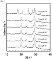
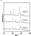
- T H , T L , T C , and T ⁇ can be determined by XRD measurement.
- T ⁇ - T H preferably meets T ⁇ - T H ⁇ 40°C, more preferably T ⁇ - T H ⁇ 50°C, further preferably T ⁇ - T H ⁇ 60°C, particularly preferably T ⁇ - T H ⁇ 70°C.
- the sulfide solid electrolyte produced according to Modification Example 2 has a wide range of heat treatment temperature in which the ion conductivity is not decreased. More specifically, even if the heat treatment temperature deviates from the intended temperature in the heat treatment step, the ion conductivity of the produced sulfide solid electrolyte may be less likely to be decreased. Accordingly, the aspect of Modification Example 2 has the advantage of being capable of producing a sulfide solid electrolyte with a high ion conductivity without the need for strict temperature control in the heat treatment step.
- This crystalline structure refers to the crystal phase described in Patent Document 2 and the like, and a crystal phase with a high Li ion conductivity.
- This crystalline structure refers to the crystal phase described in Patent Document 2 and the like, and a crystal phase with a low Li ion conductivity.
- the X-ray diffraction measurement with the CuKa line used in this specification is made in accordance with the following procedure.
- the airtight sample holder for X-ray diffraction measurement is filled with the solid electrolyte powder to be subjected to the measurement under an argon atmosphere with a dew point of -50°C or lower.
- Powder X-ray diffraction measurement is made with the use of an X-ray diffractometer ("MiniFlex II" from Rigaku Corporation).
- the diffracted X-ray is detected by a high-speed one-dimensional detector (model number: D/teX Ultra 2) through a K ⁇ filter with a thickness of 30 ⁇ m.
- the sampling width is 0.01°
- the scan speed is 5°/min
- the divergent slit width is 0.625°
- the lightreceiving slit width is 13 mm (OPEN)
- the scattering slit width is 8 mm.
- the method for producing a sulfide solid electrolyte according to the present invention is capable of suppressing, through the use of the raw material compound containing N, the element A, and the element M, the discharge of N to the outside of the system in the process of producing a sulfide solid electrolyte.
- the present inventors use the first principle calculation.
- the raw material compound is selected in accordance with the procedure described in (1) to (3).
- the first principle calculation is a calculation method of predicting properties in a non-empirical manner, which is an approach that is capable of calculating the total energy of a model including atoms with known atomic numbers and spatial coordinates, and the energy band structure of electrons.
- the calculation of the force acting on the atoms allows structural optimization, and allows the lattice constant, the stable structure at 0 K, the band gap, etc. to be calculated.
- the calculation method includes two roughly classified types of "wave function theory” system and "density functional theory” system.
- the calculation method used in the specification of the present application is based on the density functional theory.
- the defect generation energy E Ndefect of N refers to an energy value required for desorbing N from the crystalline structure to generate defects.
- the defect generation energy of N refers to a value calculated with the use of the total energy E perfect of a crystalline structure including no defects, the total energy E Nvacancy of a crystalline structure including N defects, and the chemical potential ⁇ N of an N atom, which is defined by the following formula (1).
- E Ndefect E Nvacancy + ⁇ N ⁇ E perfect
- the E Ndefect is calculated for each N-occupied site, and the E Ndefect that has the lowest value is used as the E Ndefect of the candidate material.
- composition and crystalline structure of the candidate material can be arbitrarily selected from those available from known publications, databases, and the like.
- the candidate material is not particularly limited as long as the material is a compound containing N, the element A', and the element M', but is preferably a compound that is stable under ordinary temperatures and pressures.
- the element A' is a metal element.
- the element M' is an element other than nitrogen belonging to any of Group 2 to Group 15 of the periodic table, and is an element that is different from the element A'.
- N is a nitrogen element.
- the element A' is not particularly limited, but is preferably any of an alkali metal element, an alkaline earth metal element, and an aluminum element, more preferably at least one selected from Li, Na, K, Mg, Ca, and Al, further preferably, Li. This makes it easy to operate the sulfide solid electrolyte as a battery.
- the defect generation energy of N is calculated for the candidate material represented by Li ⁇ M' ⁇ N ( ⁇ and ⁇ represent numerical values that provide stoichiometric ratios depending on the type of element M), and Li 3 N. More specifically, Li is selected as the element A'.
- B, Mg, Al, Si, P, Ca, Sr, Ti, V, Cr, Mn, Fe, Co, Ni, Zn, Ga, Ge, Sr, Y, Zr, Nb, In, Sn, Ce, Hf, Ta, and C are evaluated as the element M'.
- VASP Vienna Ab-initio Simulation Package
- the Hubbard U eff values shown in Table 1 are used as the calculation conditions for the first principle calculation for materials containing transition metal elements V, Cr, Mn, Fe, Co, and Ni where the 3d orbitals are the outermost shell orbitals, and the 3d orbitals are not closed shells in the states of cations with valences considered stable, with electrons in the 3d orbitals. Thus, the effect of electron localization in the d-orbitals is reflected in the calculation.
- the Hubbard U eff values shown in Table 1 are cited from the calculation conditions for the first principle calculation performed in the crystalline structure database: Materials Project (https://materialsproject.org/#search/materials) (as of August 22, 2019). The U eff values are obtained by searching the database for materials containing V, Cr, Mn, Fe, Co, and Ni. [Table 1] Element Ueff / eV V 3.25 Cr 3.70 Mn 3.90 Fe 5.30 Co 3.32 Ni 6.20
- the calculation model cell is designed such that the lattice constants a, b, and c are all approximately 10 ⁇ to the extent that the total number of atoms is not more than 200, in order to reduce the interaction between N defects.
- Table 2 shows the lattice constants used in the calculation of some candidate materials. [Table 2] Composition Number of atom / a / ⁇ b / ⁇ c / ⁇ ⁇ / deg. ⁇ / deg. ⁇ / deg.
- Table 3 shows the element M', and the chemical composition and defect generation energy E Ndefect of N for each candidate material.
- each element of V, Y, Ga, Ca, Ce, Sn, Zn, Ge, Cr, Mn, Sr, In, Co, Ni, and Fe has low N defect generation energy E Ndefect zf_0nT of 3.88 eV or less in Li ⁇ M' ⁇ N.
- the candidate materials containing any of V, Y, Ga, Ca, Ce, Sn, Zn, Ge, Cr, Mn, Sr, In, Co, Ni, and Fe as the element M' are predicted to be likely to generate N defects, and fail to achieve the effect of the present invention for suppressing the discharge of N to the outside of the system in the process of producing the sulfide solid electrolyte or achieve the reduced effect.
- each element of Al, Ta, Si, Sc, Mg, Nb, B, Hf, C, P, Zr, and Ti has high N defect generation energy E Ndefect of 4.00 eV or more in Li ⁇ M' ⁇ N.
- the candidate materials containing any of Al, Ta, Si, Sc, Mg, Nb, B, Hf, C, P, Zr, and Ti as the element M' are predicted to be unlikely to generate N defects, and extremely likely to achieve the effect of the present invention for suppressing the discharge of N to the outside of the system in the process of producing the sulfide solid electrolyte.
- the candidate materials are, as the defect generation energy E Ndefect of N has a larger value, predicted to, be less likely to generate N defects, and be capable of further suppressing the discharge of N to the outside of the system in the process of producing the sulfide solid electrolyte.
- the defect generation energy E Ndefect of N of the candidate material is 4.00 eV or more, preferably 4.10 eV or more, more preferably 4.20 eV or more, further preferably 4.30 eV or more, particularly preferably 4.35 eV or more.
- the calculation is performed for the case of containing Li as the element A'. More specifically, the first principle calculation is performed with Li ⁇ M' ⁇ N as a model.
- the present invention is, however, not limited thereto.
- the element A' has only to be a metal element, and for example, candidate materials containing any of Na, K, Mg, Ca, and Al as the element A' may be selected, and the raw material compound may be selected with the use of the first principle calculation.
- a sulfide solid electrolyte according to an embodiment of the present invention is a composition containing P, S, N, an element A, and an element M, which is produced by a production method including: preparing a raw material compound containing N, the element A, and the element M; reacting the composition to obtain an intermediate; and heating the intermediate to obtain a sulfide solid electrolyte.
- the sulfide solid electrolyte will be described with reference to, as an example, a case of containing Li as the element A.
- the sulfide solid electrolyte has a crystalline structure.
- the phrase "to have a crystalline structure” means that a peak derived from the crystalline structure of the sulfide solid electrolyte is observed in the X-ray diffraction pattern in the X-ray diffraction measurement.
- the sulfide solid electrolyte may contain an amorphous portion.
- Examples of the crystalline structure of the sulfide solid electrolyte include an HICP, a LGPS type, an argyrodite type, Li 7 P 3 S 11 , and Thio-LISICON series.
- the HICP, the LGPS type, the argyrodite type, and Li 7 P 3 S 11 are preferable from the viewpoint of lithium ion conductivity, and among these structures, Li 7 P 3 S 11 is more preferable because of the high stability to Li.
- the above-mentioned configuration provides a sulfide solid electrolyte capable of increasing the first coulombic efficiency of an all-solid-state battery including the solid electrolyte.
- the diffraction peaks in the first crystalline structure may fall within the above-mentioned ranges of 2 ⁇ , within the ranges of ⁇ 0.3°, or within the ranges of ⁇ 0.1°.
- LGPS-type sulfide solid electrolyte examples include Li 10 GeP 2 S 12 .
- Examples of the argyrodite-type sulfide solid electrolyte include Li 6 PS 5 Cl.
- the sulfide solid electrolyte preferably contains, as a main component, an anion structure that has a so-called ortho composition.
- the electrolyte preferably contains the PS 4 3- structure as a main component.
- the "main component” herein means that the ratio of a specific component to all of the components is 50 mol% or more.
- the content of the anion structure that has an ortho composition to the whole anion structure constituting the sulfide solid electrolyte is 50 mol% or more and less than 100 mol%, preferably 60 mol% or more and less than 100 mol%, more preferably 70 mol% or more and less than 100 mol%, further preferably 80 mol% or more and less than 100 mol%, particularly preferably 90 mol% or more and less than 100 mol%.
- the sulfide solid electrolyte preferably contains substantially no cross-linked sulfur. Since cross-linked sulfur reacts with water to produce hydrogen sulfide, atmospheric stability can be improved by containing substantially no cross-linked sulfur.
- the electrolyte in the case where the sulfide solid electrolyte is a Li 2 S-P 2 S 5 -based solid electrolyte, the electrolyte preferably contains substantially no S 3 P-S-PS 3 structure.
- Containing substantially no cross-linked sulfur can be confirmed by the fact that the peak corresponding to the cross-linked sulfur structure is not detected in measuring the Raman spectroscopy spectrum with a laser of 532 nm in excitation wavelength.
- containing substantially no S 3 P-S-PS 3 structure can be confirmed by the fact that no peak is detected at 402 cm -1 in measuring the Raman spectroscopy spectrum with a laser of 532 nm in excitation wavelength.
- the sulfide solid electrolyte is allowed to contain a small amount of crosslinked sulfur.
- the ratio I P /I O of the intensity I P of the peak belonging to cross-linked sulfur to the intensity I O of the peak belonging to the anion structure of the ortho composition in Raman spectroscopy spectrum measurement is preferably 0.7 or less, more preferably 0.5 or less, further preferably 0.35 or less.
- the peak intensity at 417 cm -1 derived from the PS 4 3- structure corresponds to the I O mentioned above
- the peak intensity at 402 cm -1 derived from the S 3 P-S-PS 3 structure corresponds to the I P mentioned above.
- the sulfide solid electrolyte preferably contains substantially no Li 2 S. Since Li 2 S reacts with water to produce hydrogen sulfide, atmospheric stability can be improved by containing substantially no Li 2 S.
- the sulfide solid electrolyte may possibly have atmospheric stability decreased because of the precipitation of Li 2 S in the case where the Li content is high, or have an ion conductivity decreased in the case where the Li content is low. Further, the sulfide solid electrolyte may possibly have atmospheric stability decreased because of the precipitation of Li 2 S in the case where the content of N is high, or fail to sufficiently produce the effects of containing N such as improved atmospheric stability in the case where the content of N is low.
- the element ratios of the sulfide solid electrolyte preferably satisfy the following formulas respectively in terms of mole ratio at the same time. 2.30 ⁇ Li / P ⁇ 4.20 0.01 00 ⁇ N / P ⁇ 1.20
- Li/P and N/P more preferably satisfy the following formulas at the same time. 2.36 ⁇ Li / P ⁇ 4.12 0.02 00 ⁇ N / P ⁇ 1.11
- Li/P and N/P further preferably satisfy the following formulas at the same time. 2.36 ⁇ Li / P ⁇ 4.00 0.06 00 ⁇ N / P ⁇ 0.900
- Li/P and N/P even more preferably satisfy the following formulas at the same time. 2.60 ⁇ Li / P ⁇ 3.40 0.190 ⁇ N / P ⁇ 0.710
- the above Li/P and the above N/P satisfy the following equations at the same time. 2.77 ⁇ Li / P ⁇ 3.38 0.280 ⁇ N / P ⁇ 0.650
- the sulfide solid electrolyte preferably has a composition represented by the general formula (100 - z)(yLi 2 S ⁇ (1 - y)P 2 S 5 ) ⁇ zLi ⁇ M ⁇ N (where 0 ⁇ z ⁇ 40, 0.50 ⁇ y ⁇ 0.75, and ⁇ represent numerical values that provide stoichiometric ratios depending on the type of the element M).
- the sulfide solid electrolyte has a composition represented by the general formula mentioned above, the atmospheric stability and the ion conductivity at 25°C can be further improved. It is to be noted that the general formula mentioned above is intended to show the content ratios of Li, S, P, N, and the element M, and not intended to specify that the composition is composed of Li 2 S, P 2 S 5 , and Li ⁇ M ⁇ N.
- the lower limit of the ion conductivity of the sulfide solid electrolyte at 25°C is preferably 0.4 ⁇ 10 -3 S/cm, more preferably 1.0 ⁇ 10 -3 S/cm, further preferably 1.5 ⁇ 10 -3 S/cm.
- the ion conductivity of the sulfide solid electrolyte at 25°C falls within the range mentioned above, thereby allowing the rate characteristics of an all-solid-state battery to be improved.
- the ion conductivity of the sulfide solid electrolyte at 25°C is determined from measurement of the alternating-current impedance by the following method. Under an argon atmosphere with a dew point of -50°C or lower, 120 mg of the sample powder is put into a powder molder of 10 mm in inner diameter, and then subjected to uniaxial pressing at a pressure of 50 MPa or less per sample area with the use of a hydraulic press. After pressure release, a SUS316L powder is put as a current collector onto the upper and lower surfaces of the sample, and then subjected to uniaxial pressing at a pressure of 360 MPa per pellet area for 5 minutes, thereby providing a pellet for ion conductivity measurement.
- This pellet for ion conductivity measurement is inserted into an HS cell from Hohsen Corp. to measure the alternating-current impedance.
- the measurement conditions are an applied voltage amplitude of 20 mV, a frequency range of 1 MHz to 100 mHz, and a measurement temperature of 25°C.
- the sulfide solid electrolyte can be suitably used as a solid electrolyte for an all-solid-state battery.
- a sulfide solid electrolyte according to another embodiment of the present invention contains Li, P, S, N, an element X, and an element M.
- the element X represents at least one element selected from the group consisting of Cl, Br, and I.
- the sulfide solid electrolyte may contain one selected from the group consisting of Al, B, and Si as the element M, and may contain Al as the element M.
- the sulfide solid electrolyte may possibly have no HICP deposited because of the precipitation of Li 2 S in the case where the Li content is high, or have an ion conductivity decreased in the case where the Li content is low. Further, the sulfide solid electrolyte may possibly have atmospheric stability decreased because of the precipitation of Li 2 S in the case where the content of N is high, or fail to sufficiently produce the effects of containing N in the case where the content of N is low.
- a crystal phase of lithium halide may remain in the sulfide solid electrolyte, thereby decreasing the ion conductivity, or the effect of containing the element X may possibly fail to be sufficiently produced in the case where content is low.
- the content ratio Li/P of the Li to the P, the content ratio N/P of the N to the P, and the content ratio X/P of the X to the P preferably satisfy the following formulas respectively in terms of mole ratio at the same time. 3.10 ⁇ Li / P ⁇ 4.20 0.0600 ⁇ N / P ⁇ 0.750 0.180 ⁇ X / P ⁇ 1.30
- Li/P, N/P, and X/P more preferably satisfy the following formulas at the same time. 3.10 ⁇ Li / P ⁇ 3.90 0.0900 ⁇ N / P ⁇ 0.750 0.180 ⁇ X / P ⁇ 1.00
- the sulfide solid electrolyte has a composition represented by the general formula (100 - z) ⁇ (1 - y)[xLi 2 S ⁇ (1 - x)P 2 S 5 ] ⁇ yLi ⁇ M ⁇ N ⁇ zLiX (where 0.50 ⁇ x ⁇ 0.80, 0 ⁇ y ⁇ 0.50, 5 ⁇ z ⁇ 40, ⁇ and ⁇ represent numerical values that provide stoichiometric ratios depending on the type of element M), and more preferably, x, y, and z respectively meet 0.67 ⁇ x ⁇ 0.73, 0.10 ⁇ y ⁇ 0.30 and 10 ⁇ z ⁇ 30.
- the sulfide solid electrolyte has a composition represented by the general formula mentioned above, the thermal stability of the HICP can be further improved.
- the general formula mentioned above can be also expressed by (100 - z 1 - z 2 ) ⁇ (1 - y)[xLi 2 S ⁇ (1 - x)P 2 S 5 ] ⁇ yLi ⁇ M ⁇ N ⁇ z i LiX 1 ⁇ z 2 LiX 2 (where 0.50 ⁇ x ⁇ 0.80, 0 ⁇ y ⁇ 0.50, 5 ⁇ (z 1 + z 2 ) ⁇ 40, ⁇ and ⁇ represent numerical values that provide stoichiometric ratios depending on the type of element M), and x, y, z 1 , and z 2 in this case preferably respectively meet 0.67 ⁇ x ⁇ 0.73, 0.10 ⁇ y ⁇ 0.30, and 10 ⁇ (z 1 + z 2 ) ⁇ 30.
- the general formula mentioned above is intended to show the content ratios of Li, S, P, N, the element M, and the element X, and not intended to specify that the composition is composed of Li 2 S, P 2 S 5 , Li ⁇ M ⁇ N, and LiX.
- x, y, and z preferably respectively meet 0.50 ⁇ x ⁇ 0.80, 0 ⁇ y ⁇ 0.50, and 5 ⁇ z ⁇ 40, more preferably 0.60 ⁇ x ⁇ 0.75, 0.050 ⁇ y ⁇ 0.40, and 10 ⁇ z ⁇ 30, further preferably 0.67 ⁇ x ⁇ 0.73, 0.10 ⁇ y ⁇ 0.30, and 15 ⁇ z ⁇ 25.
- the sulfide solid electrolyte preferably contains, as the element X, Br or I alone, more preferably Br alone. In addition, it is also preferable to contain Br and I at the same time.
- the content of Br with respect to the total amount of Br and I contained in the sulfide solid electrolyte is preferably 1 mol% or more and 99 mol% or less, more preferably 5 mol% or more and 80 mol% or less.
- the diffraction peak intensity ratio I L /I H indicates the abundance ratio between the HICP and LICP included in the sulfide solid electrolyte. More specifically, the fact that the diffraction peak intensity ratio I L /I H is low indicates that the amount of the LICP is relatively small with respect to the HICP.
- the ion conductivity of the sulfide solid electrolyte according to Embodiment 2 at 25°C is preferably 2.0 ⁇ 10 -3 S/cm or more, more preferably 2.5 ⁇ 10 -3 S/cm or more, further preferably 3.0 ⁇ 10 -3 S/cm or more, particularly preferably 4.0 ⁇ 10 -3 S/cm or more.
- the configuration mentioned above allows the high rate discharge performance of the all-solid-state battery including the sulfide solid electrolyte to be improved.
- the all-solid-state battery includes a negative electrode layer, a solid electrolyte layer, and a positive electrode layer.
- Fig. 2 is a schematic cross-sectional view illustrating an all-solid-state battery according to an embodiment of the present invention.
- the all-solid-state battery 10 which serves as a secondary battery, has a negative electrode layer 1 and a positive electrode layer 2 disposed with a solid electrolyte layer 3 interposed therebetween.
- the negative electrode layer 1 has a negative electrode substrate layer 4 and a negative composite layer 5, and the negative electrode substrate layer 4 serves as the outermost layer of the negative electrode layer 1.
- the positive electrode layer 2 has a positive electrode substrate layer 7 and a positive composite layer 6, and the positive electrode substrate layer 7 serves as the outermost layer of the positive electrode layer 2.
- the positive composite layer 6, the solid electrolyte layer 3, the negative composite layer 5, and the negative electrode substrate layer 4 are stacked in this order on the positive electrode substrate layer 7.
- the negative electrode layer 1, the solid electrolyte layer 3, the positive electrode layer 2, or a combination thereof contains the sulfide solid electrolyte.
- the negative electrode layer 1, the solid electrolyte layer 3, the positive electrode layer 2, or a combination thereof contains the sulfide solid electrolyte, and the first coulombic efficiency is thus excellent.
- the sulfide solid electrolyte has excellent reduction resistance
- the negative electrode layer 1 and/or the solid electrolyte layer 3 preferably contain the sulfide solid electrolyte. The configuration mentioned above makes the effect of the present invention much greater.
- the all-solid-state battery may be used in combination with other solid electrolytes besides the sulfide solid electrolyte.
- the other solid electrolytes may be sulfide solid electrolytes other than the sulfide solid electrolyte described above, or may be oxide-based solid electrolytes, dry polymer electrolytes, gel polymer electrolytes, or pseudo solid electrolytes.
- the sulfide solid electrolytes other than the sulfide solid electrolyte described above preferably has high Li ion conductivity, and examples thereof can include Li 2 S-P 2 S 5 , Li 2 S-P 2 S 5 -LiI, Li 2 S-P 2 S 5 -LiCl, Li 2 S-P 2 S 5 -LiBr, Li 2 SP 2 S 5 -Li 2 O, Li 2 S-P 2 S 5 -Li 2 O-LiI, Li 2 S-P 2 S 5 -Li 3 N, Li 2 S-SiS 2 , Li 2 S-SiS 2 -LiI, Li 2 S-SiS 2 -LiBr, Li 2 S-SiS 2 -LiCl, Li 2 S-SiS 2 -B 2 S 3 -LiI, Li 2 S-SiS 2 -P 2 S 5 -LiI, Li 2 S-B 2 S 3 , Li 2 SP 2 S 5 -
- Li 2 S-P 2 S 5 Li 10 GeP 2 S 12 , and the like are preferable from the viewpoint of favorable lithium ion conductivity.
- xLi 2 S ⁇ (100 - x)P 2 S 5 70 ⁇ x ⁇ 80 is preferable.
- the negative electrode layer 1 includes the negative electrode substrate layer 4 and the negative composite layer 5 stacked on the surface of the negative electrode substrate layer 4.
- the negative electrode layer 1 may have an intermediate layer, not shown, between the negative electrode substrate layer 4 and the negative composite layer 5.
- the negative electrode substrate layer 4 is a layer with conductivity.
- the material of the negative electrode substrate layer 4 is not limited as long as the material is a conductor.
- Examples of the material can include one or more metals selected from the group consisting of copper, aluminum, titanium, nickel, tantalum, niobium, hafnium, zirconium, zinc, tungsten, bismuth, antimony, gold, silver, iron, platinum, chromium, tin, and indium, and alloys containing one or more of these metals, as well as stainless-steel alloys.
- the lower limit of the average thickness of the negative electrode substrate layer 4 is preferably 3 pm, more preferably 5 pm, further preferably 8 pm.
- the upper limit of the average thickness of the negative electrode substrate layer 4 is preferably 200 pm, more preferably 100 pm, further preferably 50 pm.
- the average thickness of the negative electrode substrate layer 4 is adjusted to be equal to or more than the lower limit mentioned above, thereby allowing the strength of the negative electrode substrate layer 4 to be sufficiently increased, and thus allowing the negative electrode layer 1 to be favorably formed.
- the average thickness of the negative electrode substrate layer 4 is adjusted to be equal to or less than the upper limit mentioned above, thereby allowing the volumes of other constituent elements to be sufficiently secured.
- the negative composite layer 5 can be formed from a so-called negative composite including a negative active material.
- the negative composite may contain a negative electrode mixture or a negative electrode composite containing the negative active material and the sulfide solid electrolyte.
- the negative composite contains, if necessary, optional components such as a solid electrolyte other than the sulfide solid electrolyte, a conductive agent, a binder, and a filler.
- negative active material a material capable of occluding and releasing lithium ions is typically used.
- Specific negative active materials include metallic lithium; metals or semimetals such as Si and Sn; metal oxides or semimetal oxides such as Si oxides and Sn oxides; polyphosphate compounds; carbon materials such as graphite, non-graphitic carbon (graphitizable carbon or non-graphitizable carbon); and lithium metal composite oxides such as lithium titanate.
- the lower limit of the content of the negative active material in the negative composite is preferably 10% by mass, more preferably 15% by mass.
- the upper limit of the content of the negative active material is preferably 60% by mass, more preferably 70% by mass, further preferably 80% by mass, particularly preferably 90% by mass, and may be 95% by mass.
- the content of the negative active material falls within the range mentioned above, thereby allowing the electric capacity of the all-solid-state battery to be increased.
- the negative electrode mixture is a mixture prepared by mixing the negative active material and the sulfide solid electrolyte by mechanical milling or the like.
- the mixture of the negative active material and the sulfide solid electrolyte can be obtained by mixing the particulate negative active material and the particulate sulfide solid electrolyte.
- Examples of the negative electrode composite include a composite with a chemical or physical bond between the negative active material and the sulfide solid electrolyte, and a composite mechanically formed from the negative active material and the sulfide solid electrolyte.
- the composite mentioned above has the negative active material and the sulfide solid electrolyte present in one particle, and examples of the composite include an aggregate formed by the negative active material and the sulfide solid electrolyte, and the negative active material with a film containing the sulfide solid electrolyte, formed on at least a part of the surface of the material.
- the negative electrode mixture or the negative composite may contain a solid electrolyte other than the sulfide solid electrolyte.
- the negative active material and sulfide solid electrolyte contained in the negative composite constitute the negative electrode mixture or the negative electrode composite, thereby allowing the ion conductivity to be improved.
- the lower limit of the content of the solid electrolyte in the negative composite may be 5% by mass, and is preferably 10% by mass.
- the upper limit of the content of the solid electrolyte in the negative composite is preferably 90% by mass, more preferably 85% by mass, further preferably 80% by mass, particularly preferably 75% by mass.
- the content of the solid electrolyte falls within the range mentioned above, thereby allowing the electric capacity of the all-solid-state battery to be increased.
- the negative composite may contain the sulfide solid electrolyte, or may contain a solid electrolyte other than the sulfide solid electrolyte.
- the conductive agent mentioned above is not particularly limited.
- examples of such a conductive agent include natural or artificial graphite, carbon black such as furnace black, acetylene black, and ketjen black, metals, and conductive ceramics.
- Examples of the form of the conductive agent include powdery and fibrous forms.
- the content of the conductive agent in the negative composite can be, for example, 0.5% by mass or more and 30% by mass or less.
- the negative composite may contain no conductive agent.
- the binder (binding agent) mentioned above is not particularly limited.
- the binder include thermoplastic resins such as fluororesins (polytetrafluoroethylene (PTFE), polyvinylidene fluoride (PVDF), etc.), polyethylene, polypropylene, polyimide, and polyacrylic acid; elastomers such as an ethylene-propylene-diene rubber (EPDM), sulfonated EPDM, a styrene-butadiene rubber (SBR), and fluororubber; and polysaccharide polymers.
- thermoplastic resins such as fluororesins (polytetrafluoroethylene (PTFE), polyvinylidene fluoride (PVDF), etc.), polyethylene, polypropylene, polyimide, and polyacrylic acid
- elastomers such as an ethylene-propylene-diene rubber (EPDM), sulfonated EPDM, a styrene-butadiene rubber
- the filler mentioned above is not particularly limited.
- the main component of the filler include polyolefins such as polypropylene and polyethylene, silica, alumina, zeolite, glass, and carbon.
- the lower limit of the average thickness of the negative composite layer 5 is preferably 30 pm, more preferably 60 pm.
- the upper limit of the average thickness of the negative composite layer 5 is preferably 1000 pm, more preferably 500 pm, further preferably 200 pm.
- the average thickness of the negative composite layer 5 is adjusted to be equal to or more than the lower limit mentioned above, thereby making it possible to obtain an all-solid-state battery with a high energy density.
- the average thickness of the negative composite layer 5 is adjusted to be equal to or less than the upper limit mentioned above, thereby making it possible to obtain an all-solid-state battery including a negative electrode that is excellent in rate characteristics and high in active material utilization.
- the intermediate layer mentioned above which is a coating layer on the surface of the negative electrode substrate layer 4, includes conductive particles such as carbon particles, thereby reducing the contact resistance between the negative electrode substrate layer 4 and the negative composite layer 5.
- the structure of the intermediate layer is not particularly limited, and can be formed from, for example, a composition containing a resin binder and conductive particles.
- the positive electrode layer 2 includes the positive electrode substrate layer 7 and the positive composite layer 6 stacked on the surface of the positive electrode substrate layer 7. Like the negative electrode layer 1, the positive electrode layer 2 may have an intermediate layer between the positive electrode substrate layer 7 and the positive composite layer 6. This intermediate layer may have the same structure as the intermediate layer of the negative electrode layer 1.
- the positive electrode substrate layer 7 may have the same structure as the negative electrode substrate layer 4.
- the material of the positive electrode substrate layer 7 is not limited as long as the material is a conductor.
- Examples of the material can include one or more metals selected from the group consisting of copper, aluminum, titanium, nickel, tantalum, niobium, hafnium, zirconium, zinc, tungsten, bismuth, antimony, gold, silver, iron, platinum, chromium, tin, and indium, and alloys containing one or more of these metals, as well as stainless-steel alloys.
- the lower limit of the average thickness of the positive electrode substrate layer 7 is preferably 3 ⁇ m, more preferably 5 ⁇ m.
- the upper limit of the average thickness of the positive electrode substrate layer 7 is preferably 200 ⁇ m, more preferably 100 pm, further preferably 50 pm.
- the average thickness of the positive electrode substrate layer 7 is adjusted to be equal to or more than the lower limit mentioned above, thereby allowing the strength of the positive electrode substrate layer 7 to be sufficiently increased, and thus allowing the positive electrode layer 2 to be formed favorably.
- the average thickness of the positive electrode substrate layer 7 is adjusted to be equal to or less than the upper limit mentioned above, thereby allowing the volumes of the other constituent elements to be sufficiently secured.
- the positive composite layer 6 can be formed from a so-called positive composite including a positive active material.
- the positive composite may contain a positive electrode mixture or a positive electrode composite including a positive active material and a solid electrolyte.
- the sulfide solid electrolyte may be used as the solid electrolyte mentioned above.
- the positive composite that forms the positive composite layer 6 includes optional components such as a solid electrolyte, a conductive agent, a binder, and a filler, if necessary. It is to be noted that the positive composite layer may have a form containing no solid electrolyte.
- the positive active material included in the positive composite layer 6 known materials typically for use in all-solid-state batteries can be used.
- the positive active material include composite oxides represented by Li x MeO y (Me represents at least one transition metal) (Li x CoO 2 , Li x NiO 2 , Li x MnO 3 , Li x Ni ⁇ Co (1- ⁇ ) O 2 , Li x Ni ⁇ Mn ⁇ Co (1- ⁇ - ⁇ ) O 2 , and the like that have a layered ⁇ -NaFeO 2 -type crystalline structure, and Li x Mn 2 O 4 , Li x Ni ⁇ Mn (2- ⁇ ) O 4 , and the like that have a spinel-type crystalline structure), and polyanion compounds represented by Li w Me x (AO y ) z (Me represents at least one transition metal, and A represents, for example, P, Si, B, V, or the like) (LiFePO 4 , LiMnPO 4 , LiN
- Lithium alloys such as Li-Al, Li-In, Li-Sn, Li-Pb, Li-Bi, Li-Ga, Li-Sr, Li-Si, Li-Zn, Li-Cd, Li-Ca, and Li-Ba, and materials that are more electropositive in oxidation-reduction potential than the negative electrode material, other than the compounds represented by the general formulas mentioned above, such as MnO 2 , FeO 2 , TiO 2 , V 2 O 5 , V 6 O 13 , and TiS 2 can be used as the positive active material.
- the lower limit of the content of the positive active material in the positive composite is preferably 10% by mass, more preferably 15% by mass.
- the upper limit of the content of the positive active material is preferably 60% by mass, more preferably 70% by mass, further preferably 80% by mass, particularly preferably 90% by mass, and may be 95% by mass.
- the content of the positive active material falls within the range mentioned above, thereby allowing the electric capacity of the all-solid-state battery to be increased.
- the positive electrode mixture is a mixture prepared by mixing the positive active material and a solid electrolyte or the like by mechanical milling or the like, as in the case of the negative electrode.
- the mixture of the positive active material and the solid electrolyte or the like can be obtained by mixing the particulate positive active material and the particulate solid electrolyte or the like.
- Examples of the positive electrode composite also include, as in the case of the negative electrode, a composite with a chemical or physical bond between the positive active material and the solid electrolyte or the like, and a composite mechanically formed from the positive active material and the solid electrolyte or the like.
- the composite mentioned above has the positive active material and the solid electrolyte or the like present in one particle, and examples of the composite include an aggregate formed by the positive active material and the solid electrolyte or the like, and the positive active material with a film containing the solid electrolyte or the like, formed on at least a part of the surface of the material.
- the positive electrode mixture or the positive electrode composite may contain a solid electrolyte other than the sulfide solid electrolyte.
- the positive active material and the solid electrolyte or the like contained in the positive composite constitute the positive electrode mixture or the positive electrode composite, thereby allowing the ion conductivity to be improved.
- the lower limit of the content of the solid electrolyte may be 5% by mass, and is preferably 10% by mass.
- the upper limit of the content of the solid electrolyte in the positive composite is preferably 90% by mass, more preferably 85% by mass, further preferably 80% by mass, particularly preferably 75% by mass.
- the content of the solid electrolyte falls within the range mentioned above, thereby allowing the electric capacity of the all-solid-state battery to be increased.
- the lower limit of the average thickness of the positive composite layer 6 is preferably 30 ⁇ m, more preferably 60 ⁇ m.
- the upper limit of the average thickness of the positive composite layer 6 is preferably 1000 ⁇ m, more preferably 500 ⁇ m, further preferably 200 ⁇ m.
- the average thickness of the positive composite layer 6 is adjusted to be equal to or more than the lower limit mentioned above, thereby making it possible to obtain an all-solid-state battery with a high energy density.
- the average thickness of the positive composite layer 6 is adjusted to be equal to or less than the upper limit mentioned above, thereby making it possible to obtain an all-solid-state battery including a negative electrode that is excellent in high rate discharge performance and high in active material utilization.
- the solid electrolyte layer 3 contains an electrolyte for solid electrolyte layers.
- the electrolyte for solid electrolyte layers can include oxide-based solid electrolytes, other sulfide solid electrolytes, dry polymer electrolytes, gel polymer electrolytes, and pseudo solid electrolytes, besides the sulfide solid electrolyte described above.
- these electrolytes from viewpoints such as favorable ion conductivity and easy interface formation, sulfide solid electrolytes are preferable, and the sulfide solid electrolyte described above is more preferable.
- the solid electrolyte layer 3 contains the sulfide solid electrolyte, thereby allowing the solid electrolyte layer to exhibit a high ion conductivity, and thus allowing the internal resistance of the all-solid-state battery to be reduced.
- the content of the sulfide solid electrolyte with respect to the total amount of the solid electrolytes included in the all-solid-state battery is preferably 50% by mass or more and 100% by mass or less, more preferably 70% by mass or more and 100% by mass or less, further preferably 80% by mass or more and 100% by mass or less, even more preferably 90% by mass or more and 100% by mass or less.
- the solid electrolyte included in the all-solid-state battery is preferably composed only of the sulfide solid electrolyte.
- the all-solid-state battery configured as mentioned above makes it possible to fully enjoy the advantage of the all-solid-state battery that allows the raised upper limit of the operating temperature of the battery.
- the electrolyte for solid electrolyte layers may have a crystalline structure, or may be amorphous without having a crystalline structure. Oxides such as Li 3 PO 4 , halogens, halogen compounds, and the like may be added to the electrolyte for solid electrolyte layers.
- the average thickness of the solid electrolyte layer 3 is preferably 1 pm or more and 50 pm or less, more preferably 3 pm or more and 20 pm or less.
- the average thickness of the solid electrolyte layer 3 falls within the range mentioned above, thereby making it possible to reliably insulate the positive electrode and the negative electrode while increasing the energy density of the all-solid-state battery.
- the method for manufacturing the all-solid-state battery mainly includes, for example, a sulfide solid electrolyte preparation step, a negative composite preparation step, a step of preparing an electrolyte for solid electrolyte layers, a positive composite preparation step, and a stacking step of stacking a negative electrode layer, a solid electrolyte layer, and a positive electrode layer.
- a sulfide solid electrolyte is prepared by the method for producing a sulfide solid electrolyte.
- a negative composite for forming the negative electrode layer is prepared.
- this step includes, for example, using a mechanical milling method or the like to mix the negative active material and the sulfide solid electrolyte and prepare a mixture or a composite of the negative active material and the sulfide solid electrolyte.
- the electrolyte for solid electrolyte layers for forming the solid electrolyte layer is prepared.
- the electrolyte can be obtained through treatment of predetermined materials for the electrolyte for solid electrolyte layers by a mechanical milling method.
- the electrolyte for solid electrolyte layers may be prepared by heating predetermined materials for the electrolyte for solid electrolyte layers to the melting temperature or higher to melt and mix the both materials at a predetermined ratio and quench the mixture in accordance with a melt quenching method.
- a positive composite for forming the positive electrode layer is prepared.
- the method for preparing the positive composite is not particularly limited, and may be selected appropriately depending on the purpose. Examples of the method include compression molding of the positive active material, mechanical milling treatment of predetermined materials for the positive composite, and sputtering with a target material for the positive active material.
- this step includes, for example, using a mechanical milling method or the like to mix the positive active material and the sulfide solid electrolyte and prepare a mixture or a composite of the positive active material and the sulfide solid electrolyte.
- the negative electrode layer including the negative electrode substrate layer and the negative composite layer, the solid electrolyte layer, and the positive electrode layer including the positive electrode substrate layer and the positive composite layer are stacked.
- the negative electrode layer, the solid electrolyte layer, and the positive electrode layer may be formed in sequence, or vice versa, and the order of forming the respective layers is not particularly limited.
- the negative electrode layer is formed by pressure molding of the negative electrode substrate and the negative composite
- the solid electrolyte layer is formed by pressure molding of the electrolyte for solid electrolyte layers
- the positive electrode layer is formed by pressure molding of the positive electrode substrate and the positive composite.
- the negative electrode layer, the solid electrolyte layer, and the positive electrode layer may be stacked by pressure molding of the negative electrode substrate, the negative composite, the electrolyte for solid electrolyte layers, the positive electrode substrate, and the positive composite at the same time.
- the positive electrode layer, the negative electrode layer, or these layers may be molded in advance, and subjected to pressure molding with the solid electrolyte layer to stack the layers.
- the present invention is not to be considered limited to the embodiment mentioned above, and can be put into practice in various modified and improved aspects, besides the aspects mentioned above.
- the raw material compound containing N, element A, and element M has been described with reference to the raw material compound containing only N, Li, and the element M as an example in the above embodiment, the present invention is not limited thereto.
- the raw material compound containing N, element A, and the element M may further contain other elements as long as the present invention can solve the problems.
- the configuration of the all-solid-state battery according to the present invention is not to be considered particularly limited, and may include other layers such as an intermediate layer and an adhesive layer, besides the negative electrode layer, the positive electrode layer, and the solid electrolyte layer.
- Li 3 N and AlN were weighed so as to be 1.2 : 1 in terms of mole ratio, mixed in a mortar, and then pelletized.
- Li 3/2 Al 1/2 N was prepared by heat treatment at 750°C for 1 hour. It was confirmed by XRD measurement that the main phase of the prepared Li 3/2 Al 1/2 N was Li 3/2 Al 1/2 N.
- Li 2 S 99.98%, Aldrich
- P 2 S 5 99%, Aldrich
- Li 3/2 Al 1/2 N were weighed so as to be 56 : 24 : 20 in terms of mole ratio, and then mixed in a mortar to prepare a composition containing Li, P, S, N, and Al.
- the above-mentioned composition was put in a hermetically sealed 80 mL zirconia pot containing 160 g of zirconia balls with a diameter of 4 mm.
- the sample was subjected to milling treatment for 45 hours at a revolution speed of 510 rpm with a planetary ball mill (from FRITSCH, model number: Premium line P-7), thereby providing an intermediate.
- the above-mentioned intermediate was subjected to a heat treatment for 2 hours to obtain a sulfide solid electrolyte.
- This heat treatment was performed at a temperature that was equal to or higher than the crystallization temperature and not 100°C higher than the crystallization temperature.
- the crystallization temperature was determined by measuring the DSC. The DSC measurement was made under the following conditions. More specifically, the temperature was raised from room temperature to 400°C at 10°C/min with the use of a DSC device (Thermo Plus DSC8230 from Rigaku Corporation) and a hermetically sealed pan made of SUS.
- composition, intermediate, and sulfide solid electrolyte prepared in accordance with the above-mentioned synthesis procedure were respectively referred to as a sample a, a sample b, and a sample c.
- Li 3 N and BN were weighed so as to be 1.1 : 1 in terms of mole ratio, mixed in a mortar, and then pelletized.
- Li 3/2 B 1/2 N was prepared by heat treatment at 800°C for 10 minutes. It was confirmed by XRD measurement that the main phase of the prepared Li 3/2 B 1/2 N was Li 3/2 B 1/2 N.
- Li 2 S 99.98%, Aldrich
- P 2 S 5 99%, Aldrich
- Li 3/2 B 1/2 N were weighed so as to be 56 : 24 : 20 in terms of mole ratio, and then mixed in a mortar to prepare a composition containing Li, P, S, N, and B.
- Li 2 S 99.98%, Aldrich
- P 2 S 5 99%, Aldrich
- Li 3 N were weighed so as to be 56.8 : 27.0 : 16.2 in terms of mole ratio, and then mixed in a mortar to prepare a composition containing Li, P, S, and N.
- Li 2 S 99.98%, Aldrich
- P 2 S 5 99%, Aldrich
- Li 3 N and AlN were weighed so as to be 56 : 24 : 10 : 10 in terms of mole ratio, and then mixed in a mortar to prepare a composition containing Li, P, S, N, and Al.
- Li 3 N and VN were weighed so as to be 3 : 1 in terms of mole ratio, mixed in a mortar, and then pelletized.
- Li 7/4 V 1/4 N was prepared by heat treatment at 750°C for 10 hours. It was confirmed by XRD measurement that the main phase of the prepared Li 7/4 V 1/4 N was Li 7/4 V 1/4 N.
- Li 2 S 99.98%, Aldrich
- P 2 S 5 99%, Aldrich
- Li 7/4 V 1/4 N were weighed so as to be 56 : 24 : 20 in terms of mole ratio, and then mixed in a mortar to prepare a composition containing Li, P, S, N, and V
- X-ray diffraction measurement was made by the following method. With the use of airtight sample holder for X-ray diffraction measurement, the sulfide solid electrolyte powders according to the examples and comparative examples were packed under an argon atmosphere with a dew point of -50°C or lower. Powder X-ray diffraction measurement was made with the use of an X-ray diffractometer ("miniFlex II" from Rigaku Corporation).
- the radiation source was a CuKa line
- the tube voltage was 30 kV
- the tube current was 15 mA
- diffracted X-rays were detected by a high-speed one-dimensional detector (model number: D/teX Ultra 2) through a K ⁇ filter with a thickness of 30 ⁇ m.
- the sampling width was 0.01°
- the scan speed was 5°/min
- the divergent slit width was 0.625°
- the light receiving slit width was 13 mm (OPEN)
- the scattering slit width was 8 mm.
- the ion conductivity at 25°C was determined by measuring the alternating-current impedance with the use of "VMP-300" from (Bio-Logic) in accordance with the method described above. It is to be noted that for some of the examples and comparative examples, the ion conductivity was also measured at each temperature of -30°C, -20°C, -10°C, 0°C, and 50°C, and the activation energy (E a ) was calculated by the Arrhenius equation.
- Table 4 shows the XRD patterns and the ion conductivity ( ⁇ 25 ) at 25°C for Example 1, Example 2, Comparative Example 1, Comparative Example 2, and Comparative Example 3.
- the sulfide solid electrolytes according to all of the examples and comparative examples have peaks observed in the XRD spectra, and have the specific crystalline structure A.
- the sulfide solid electrolytes according to Example 1, Example 2, and Comparative Example 3 show the same level of ion conductivity.
- Example 1, Example 2, Comparative Example 1, Comparative Example 2, and Comparative Example 3 can be considered to have similar structures.
- Example 1 Specific Crystalline Structure A 1.7 ⁇ 10 -3
- Example 2 Specific Crystalline Structure A 1.5 ⁇ 10 -3
- Comparative Example 1 Specific Crystalline Structure A - Comparative Example 2
- Specific Crystalline Structure A - Comparative Example 3 Specific Crystalline Structure A 1.5 ⁇ 10 -3
- Example 2 For each of the samples according to Example 1, Example 2, Comparative Example 1 and Comparative Example 2, the contents of Li, B, Al, and P in the sample were determined with the use of an ICP emission spectrophotometer. In addition, for each of the samples according to Example 1, Example 2, and Comparative Examples 1 to 3, the content of N in the sample was determined with the use of an oxygen/nitrogen/hydrogen analyzer. From this analysis result, the rate of change in the content ratio of N in the sample was calculated. Table 5 shows the analysis results. It is to be noted that "no change" in the table indicates that the rate of change in the content ratio of N for the sample a was ⁇ 5% by mass or less.
- Example 1 and Example 2 undergo extraordinarily little change in the content ratio of N in the sample a, the sample b, and the sample c. More specifically, it is determined that Example 1 and Example 2 undergo extraordinarily little change in the content of N even through each step of the reaction step and the heat treatment step, thereby suppressing the discharge of N to the outside of the system.
- a sulfide solid electrolyte represented by the compositional formula 85(0.80(0.70Li 2 S ⁇ 0.30P 2 S 5 ) ⁇ 0.20Li 3/2 Al 1/2 N) ⁇ 10LiBr ⁇ 5LiI was synthesized by the following treatment.
- Li 3 N and AlN were weighed so as to be 1.2 : 1 in terms of mole ratio, mixed in a mortar, and then pelletized.
- Li 3/2 Al 1/2 N was prepared by heat treatment at 750°C for 1 hour. It was confirmed by XRD measurement that the main phase of the prepared Li 3/2 Al 1/2 N was Li 3/2 Al 1/2 N.
- Li 2 S 99.98%, Aldrich
- P 2 S 5 99%, Aldrich
- LiBr 99.999%, Aldrich
- LiI 99.999%, Aldrich
- Li 3/2 Al 1/2 N Li 2 S (99.98%, Aldrich), P 2 S 5 (99%, Aldrich), LiBr (99.999%, Aldrich), LiI (99.999%, Aldrich), and Li 3/2 Al 1/2 N were weighed so as to be 47.6 : 20.4 : 10 : 5 : 17 in terms of mole ratio, and then mixed in a mortar.
- This mixed sample was put in a hermetically sealed 80 mL zirconia pot containing 160 g of zirconia balls with a diameter of 4 mm.
- the sample was subjected to milling for 45 hours at a revolution speed of 510 rpm with a planetary ball mill (from FRITSCH, model number: Premium line P-7).
- the milled sample was subjected to a heat treatment at 245°C for 2 hours to obtain a sulfide solid electrolyte according to Example 3.
- This heat treatment temperature was set so as to be equal to or higher than the crystallization temperature, and so as not to be 100°C higher than the crystallization temperature.
- the crystallization temperature was determined by retrieving a part of the sample after the milling treatment and subjecting the part to DSC measurement.
- the DSC measurement was made under the following conditions. More specifically, the temperature was raised from room temperature to 400°C at 10°C/min with the use of a DSC device (Thermo Plus DSC8230 from Rigaku Corporation) and a hermetically sealed pan made of SUS.
- Sulfide solid electrolytes according to Comparative Example 4 and Comparative Example 5 were synthesized similarly to Example 3 except that the compositions of the sulfide solid electrolytes were changed to 85(0.75Li 2 S ⁇ 0.25P 2 S 5 ) ⁇ 10LiBr ⁇ 5LiI and 85(0.72Li 2 S ⁇ 0.25P 2 S 5 ⁇ 0.020Li 3 N) ⁇ 10LiBr.5LiI, and that the heat treatment temperatures were both set to 225°C.
- samples obtained at the heat treatment temperatures of 215°C, 230°C, 275°C, 290°C, and 310°C were also synthesized in addition to the sample obtained at the heat treatment temperature of 255°C.
- samples obtained at the heat treatment temperatures of 235°C, 290°C, 310°C, and 330°C were also synthesized in addition to the sample obtained at the heat treatment temperature of 275°C.
- samples obtained at the heat treatment temperatures of 230°C, 270°C, 290°C, 310°C, and 330°C were also synthesized in addition to the sample obtained at the heat treatment temperature of 270°C.
- samples obtained at the heat treatment temperatures of 230°C, 290°C, 310°C, and 330°C were also synthesized in addition to the sample obtained at the heat treatment temperature of 270°C.
- samples obtained at the heat treatment temperatures of 210°C and 230°C were also synthesized in addition to the sample obtained at the heat treatment temperature of 250°C.
- Example 4-1 to Example 4-6 The sulfide solid electrolytes synthesized at the respective heat treatment temperatures are respectively referred to as Example 4-1 to Example 4-6, Example 5-1 to Example 5-5, Example 6-1 to Example 6-5, Example 7-1 to Example 7-5, and Comparative Example 6-1 to Comparative Example 6-3 in ascending order of heat treatment temperature.
- Sulfide solid electrolytes according to Example 8 and Comparative Example 7 were synthesized similarly to Example 1 except that the compositions of the sulfide solid electrolytes were changed to 75(0.80(0.70Li 2 S ⁇ 0.30P 2 S 5 ) ⁇ 0.20Li 3/2 Al 1/2 N) ⁇ 15LiBr ⁇ 10LiI and 75(0.72Li 2 S ⁇ 0.25P 2 S 5 ⁇ 0.020Li 3 N) ⁇ 15LiBr ⁇ 10LiI and that the heat treatment temperatures were respectively set to 215°C and 195°C.
- Example 9 Sulfide solid electrolytes according to Example 9, Example 10, Example 11, and Comparative Example 8 were synthesized similarly to Example 3 except that the compositions of the sulfide solid electrolytes were changed to 90(0.80(0.70Li 2 S ⁇ 0.30P 2 S 5 ) ⁇ 0.20Li 3/2 Al 1/2 N) ⁇ 10LiBr, 80(0.80(0.70Li 2 S ⁇ 0.30P 2 S 5 ) ⁇ 0.20Li 3/2 Al 1/2 N) ⁇ 20LiBr, 70(0.80(0.70Li 2 S ⁇ 0.30P 2 S 5 ) ⁇ 0.20Li 3/2 Al 1/2 N) ⁇ 30LiBr, and 90(0.72Li 2 S ⁇ 0.25P 2 S 5 ⁇ 0.020Li 3 N) ⁇ 10LiBr, and that the heat treatment temperatures were respectively set to 265°C, 250°C, 240°C, and 225°C.
- Sulfide solid electrolytes according to Example 12 and Comparative Example 13 were synthesized similarly to Example 3 except that the compositions of the sulfide solid electrolytes were changed to 90(0.80(0.70Li 2 S ⁇ 0.30P 2 S 5 )0.20Li 3/2 Al 1/2 N) ⁇ 10LiI and 80(0.80(0.7Li 2 S0.30P 2 S 5 ) ⁇ 0.20Li 3/2 Al 1/2 N)20LiI and that the heat treatment temperatures were respectively set to 255°C and 240°C.
- Sulfide solid electrolytes according to Examples 14 to 17 were synthesized similarly to Example 3 except that the compositions of the sulfide solid electrolytes were changed to 80(0.97(0.745Li 2 S ⁇ 0.255P 2 S 5 ) ⁇ 0.03Li 3/2 B 1/2 N) ⁇ 12LiBr ⁇ 8LiI, 80(0.95(0.74Li 2 S ⁇ 0.26P 2 S 5 )0.05Li 3/2 B 1/2 N)12LiBr8LiI, 80(0.90(0.73Li 2 S ⁇ 0.27P 2 S 5 ) ⁇ 0.10Li 3/2 B 1/2 N) ⁇ 12LiBr ⁇ 8LiI, and 80(0.85(0.715Li 2 S ⁇ 0.285P 2 S 5 ) ⁇ 0.15Li 3/2 B 1/2 N) ⁇ 12LiBr ⁇ 8LiI, and that the heat treatment temperatures were each set to 250°C.
- Sulfide solid electrolytes according to Examples 18 to 20 were synthesized similarly to Example 3 except that the compositions of the sulfide solid electrolytes were changed to 75(0.80(0.70Li 2 S ⁇ 0.30P 2 S 5 ) ⁇ 0.20Li 3/2 B 1/2 N) ⁇ 15LiBr ⁇ 10LiI, 70(0.80(0.70Li 2 S ⁇ 0.30P 2 S 5 ) ⁇ 0.20Li 3/2 B 1/2 N) ⁇ 17LiBr ⁇ 13LiI, and 65(0.80(0.70Li 2 S ⁇ 0.30P 2 S 5 ) ⁇ 0.20Li 3/2 B 1/2 N) ⁇ 20LiBr ⁇ 15LiI, and that the heat treatment temperatures were respectively set to 230°C, 195°C, and 185°C.
- the sulfide solid electrolytes according to Examples 3 to 20 are represented by the general formulas (100 - z 1 - z 2 ) ⁇ (1 - y)[xLi 2 S ⁇ (1 - x)P 2 S 5 ] ⁇ yLi ⁇ M ⁇ N ⁇ z 1 LiX 1 ⁇ z 2 LiX 2 .
- the sulfide solid electrolytes according to Comparative Examples 5 to 7 are represented by the general formulas (100 - z 1 - z 2 ) ⁇ (x - 1.5y)Li 2 S ⁇ (1 - x)P 2 S 5 ⁇ yLi 3 N ⁇ z 1 LiX 1 ⁇ z 2 LiX 2 .
- Tables 6 to 12 show the crystalline structures identified from the XRD patterns of Examples 3 to 20 and Comparative Examples 4 to 8.
- Table 13 shows the crystalline structures identified from the XRD patterns of Examples 4-1 to 4-6, Examples 5-1 to 5-5, Examples 6-1 to 6-5, Examples 7-1 to 7-5, and Comparative Examples 6-1 to 6-3.
- the "Unknown” represents a peak from which the crystal phase is unknown.
- FIG. 3 shows the XRD patterns of Examples 4-1 to 4-6.
- Fig. 4 shows the XRD patterns of Comparative Examples 6-1 to 6-3.
- Tables 6 to 12 show the ion conductivity ( ⁇ 25 ) at 25°C and the activation energy (E a ) for Examples 3 to 20 and Comparative Examples 4 to 8.
- Table 13 shows the ion conductivity ( ⁇ 25 ) at 25°C and activation energy (E a ) for Examples 4-1 to 4-6, Examples 5-1 to 5-5, Examples 6-1 to 6-5, Examples 7-1 to 7-5, and Comparative Examples 6-1 to 6-3.
- DSC measurement was made by the following method. The temperature was raised from room temperature to 400°C at 10°C/min with the use of a DSC device (Thermo Plus DSC8230 from Rigaku Corporation) and a hermetically sealed pan made of SUS.
- a DSC device Thermo Plus DSC8230 from Rigaku Corporation
- a hermetically sealed pan made of SUS.
- the lower limit of the heat treatment temperature at which the ion conductivity is decreased is increased for the sulfide solid electrolyte according to Example 3 as compared with the sulfide solid electrolytes according to Comparative Example 4 and Comparative Example 5.
- the sulfide solid electrolyte according to Example 8 shows a high ion conductivity, in spite of the heat treatment at a higher temperature than that for the sulfide solid electrolyte according to Comparative Example 7. More specifically, it can be understood that the lower limit of the heat treatment temperature at which the ion conductivity is decreased is increased for the sulfide solid electrolyte according to Example 8 as compared with the sulfide solid electrolyte according to Comparative Example 7. This is believed to be because the phase transition of HICP to LICP was suppressed in the sulfide solid electrolyte according to Example 8.
- Example 9 has no HICP or LICP produced, whereas Example 9 has an HICP produced. More specifically, the effect of being capable of producing an HICP with a lower content of element X is recognized in the case where the sulfide solid electrolyte contains Li, P, S, N, the element X, and element M than in the case of containing no element M.
- the sulfide solid electrolytes according to Examples 6 and 14 to 17 have larger differences in temperature between the crystallization peak presumed to be derived from the HICP and the crystallization peak derived from ⁇ -Li 3 PS 4 than the sulfide solid electrolyte according to Comparative Example 6.
- the crystallization peak presumed to be derived from the HICP and the crystallization peak derived from ⁇ -Li 3 PS 4 were respectively observed at around 190°C and 260°C in Comparative Example 6, whereas the peaks were respectively observed around 190°C and 280°C in Example 14. From the foregoing, it can be understood that the sulfide solid electrolyte according to the examples widens the temperature range for the stable presence of the HICP, thereby improving the thermal stability of the high Li-ion conductive phase.
- crystallization peak presumed to be derived from the HICP in Fig. 6 refers to a peak observed in the range of approximately 180°C to 220°C.
- crystallization peaks derived from ⁇ -Li 3 PS 4 in Fig. 6 refer to the peaks observed respectively around 345°C, around 280°C, around 300°C, around 310°C, around 335°C, and around 260°C in Example 6, Examples 14 to 16, and Comparative Example 6.
- the sulfide solid electrolytes according to the examples increase the lower limit of the heat treatment temperature at which the ion conductivity is decreased, thereby widening the range of heat treatment temperature in which the ion conductivity is not decreased. More specifically, the sulfide solid electrolyte containing Li, P, S, N, the element X, and the element M was excellent in the thermal stability of the HICP. This is believed to be because the discharge of N to the outside of the system in the process of the production was suppressed, thereby sufficiently producing the effect of improving the thermal stability by the sulfide solid electrolyte containing N.
- the method for producing a sulfide solid electrolyte according to an embodiment of the present invention is capable of suppressing the discharge of N to the outside of the system, and additionally suppressing the precipitation of Li 2 S.
- the precipitation of Li 2 S can be suppressed, thereby allowing an improvement in the atmospheric stability of the sulfide solid electrolyte.
- Li 3 N and AlN were weighed so as to be 1.2 : 1 in terms of mole ratio, mixed in a mortar, and then pelletized. Next, Li 3/2 Al 1/2 N was prepared by heat treatment at 750°C for 1 hour.
- Li 2 S 99.98%, Aldrich
- P 2 S 5 99%, Aldrich
- Li 3/2 Al 1/2 N were weighed so as to be 69.3 : 29.7 : 1.0 in terms of mole ratio, and then mixed in a mortar.
- This mixed sample was put in a hermetically sealed 80 mL zirconia pot containing 160 g of zirconia balls with a diameter of 4 mm. The sample was subjected to milling for 45 hours at a revolution speed of 510 rpm with a planetary ball mill (from FRITSCH, model number: Premium line P-7).
- the milled sample was subjected to a heat treatment for 2 hours to obtain a sulfide solid electrolyte according to Example 1.
- This heat treatment was performed at a temperature that was equal to or higher than the crystallization temperature and equal to or lower than the crystallization temperature plus 100°C.
- the crystallization temperature was determined by measuring the DSC. The DSC measurement was made under the following conditions. More specifically, the temperature was raised from room temperature to 400°C at 10°C/min with the use of a DSC device (Thermo Plus DSC8230 from Rigaku Corporation) and a hermetically sealed pan made of SUS.
- Sulfide solid electrolytes according to Examples 22 to 29 were synthesized similarly to Example 21 except that the value of z in the compositional formula (100 - z)(yLi 2 S ⁇ (1 - y)P 2 S 5 ) ⁇ zLi ⁇ ⁇ M ⁇ N of the sulfide solid electrolyte was changed to 5, 7, 10, 15, 20, 25, 30, and 40.
- Li 3 N and BN were weighed so as to be 1.1 : 1 in terms of mole ratio, mixed in a mortar, then pelletized, and then subjected to a heat treatment at 800°C for 10 minutes to prepare Li 3/2 B 1/2 N.
- a heat treatment at 800°C for 10 minutes to prepare Li 3/2 B 1/2 N.
- the main phase was Li 3/2 B 1/2 N.
- Sulfide solid electrolytes according to Examples 33 to 36 were synthesized similarly to Example 21 except for changing Li ⁇ M ⁇ N to Li 3/2 B 1/2 N and changing the value of z respectively to 1, 10, 20, and 30 in the compositional formula (100 - z)(yLi 2 S ⁇ (1 - y)P 2 S 5 ) ⁇ zLi ⁇ M ⁇ N of the sulfide solid electrolyte.
- Li 3 N and Si 3 N 4 were weighed so as to be 5.1 : 1 in terms of mole ratio, mixed in a mortar, then pelletized, and then subjected to a heat treatment at 800°C for 10 minutes to prepare Li 5/3 Si 1/3 N.
- a heat treatment at 800°C for 10 minutes to prepare Li 5/3 Si 1/3 N.
- the main phase was Li 5/3 Si 1/3 N.
- Sulfide solid electrolytes according to Examples 37 to 41 were synthesized similarly to Example 21 except for changing Li ⁇ M ⁇ N to Li 5/3 Si 1/3 N and changing the value of z respectively to 1.5, 15, 20, 30, and 45 in the compositional formula (100 - z)(yLi 2 S ⁇ (1 - y)P 2 S 5 ) ⁇ zLi ⁇ ⁇ M ⁇ N of the sulfide solid electrolyte.
- a sulfide solid electrolyte according to Comparative Example 9 was synthesized similarly to Example 21 except for changing Li ⁇ M ⁇ N to Li 3 N and changing the value of z to 20 in the compositional formula (100 - z)(yLi 2 S ⁇ (1 - y)P 2 S 5 ) ⁇ zLi ⁇ M ⁇ N of the sulfide solid electrolyte.
- X-ray diffraction measurement was made by the method described above.
- the ion conductivity ( ⁇ 25 ) at 25°C was determined by measuring the alternating-current impedance with the use of "VMP-300" from (Bio-Logic) in accordance with the method described above.
- Raman spectra were measured by the following method. With the use of a laser Raman spectrophotometer ("LabRAM HR Revolution" manufactured by Horiba, Ltd.), Raman spectrometry was performed in the wave number range of 100 cm -1 to 1800 cm -1 under the conditions of excitation laser wavelength: 532 nm (YAG laser) and grating 600 gr/mm.
- the sulfide solid electrolyte according to Comparative Example 9 has only an observed peak derived from the crystalline structure of Li 2 S. From this result, it is determined that the use of Li 3 N makes Li 2 S more likely to be precipitated.
- the sulfide solid electrolytes according to Examples 27 to 29, 32, 39, and 40 have no peak of Li 2 S observed, in spite of their higher content ratios Li/P of Li to P than that of the sulfide solid electrolyte according to Comparative Example 10.
- Example 29 has no peak of Li 2 S observed in spite of the fact that the content ratio of Li to P is 4.00, which is higher than those of Comparative Example 9 and Comparative Example 10.
- the sulfide solid electrolytes according to Examples 26 and 35 have no peak of Li 2 S observed in spite of substantially the same Li/P as that of the sulfide solid electrolyte according to Comparative Example 10.
- the sulfide solid electrolyte according to Example 32 has no peak of Li 2 S observed in spite of substantially the same value of y as and the same Li/P as those of Comparative Example 10.
- the sulfide solid electrolyte tends to have Li 2 S precipitated in the case of a higher content of Li, the results were obtained as mentioned above, and it has been thus suggested that the precipitation of Li 2 S is suppressed in the method for producing the sulfide solid electrolytes according to the examples.
- Example 28 Example 29, Example 36, Example 40, and Example 41, it has been suggested that the precipitation of Li 2 S is remarkably suppressed in the case of containing Al as the element M.
- the all-solid-state battery including the sulfide solid electrolyte according to the present invention is suitably used as, for example, a lithium-ion all-solid-state battery for HEVs.
Landscapes
- Chemical & Material Sciences (AREA)
- Engineering & Computer Science (AREA)
- Chemical Kinetics & Catalysis (AREA)
- Electrochemistry (AREA)
- General Chemical & Material Sciences (AREA)
- Manufacturing & Machinery (AREA)
- Inorganic Chemistry (AREA)
- Materials Engineering (AREA)
- Organic Chemistry (AREA)
- General Physics & Mathematics (AREA)
- Condensed Matter Physics & Semiconductors (AREA)
- Physics & Mathematics (AREA)
- Secondary Cells (AREA)
- Conductive Materials (AREA)
- Battery Electrode And Active Subsutance (AREA)
- Glass Compositions (AREA)
Applications Claiming Priority (6)
| Application Number | Priority Date | Filing Date | Title |
|---|---|---|---|
| JP2018161831 | 2018-08-30 | ||
| JP2018232775 | 2018-12-12 | ||
| JP2019045347 | 2019-03-13 | ||
| JP2019103611 | 2019-06-03 | ||
| EP19854345.6A EP3828979A4 (de) | 2018-08-30 | 2019-08-30 | Verfahren zur herstellung eines sulfidfestelektrolyten, sulfidfestelektrolyt, feststoffbatterie und verfahren zur auswahl der zur herstellung des sulfidfestelektrolyten verwendeten rohstoffverbindung |
| PCT/JP2019/034139 WO2020045634A1 (ja) | 2018-08-30 | 2019-08-30 | 硫化物固体電解質の製造方法、硫化物固体電解質、全固体電池、及び硫化物固体電解質の製造に用いる原料化合物の選択方法 |
Related Parent Applications (1)
| Application Number | Title | Priority Date | Filing Date |
|---|---|---|---|
| EP19854345.6A Division EP3828979A4 (de) | 2018-08-30 | 2019-08-30 | Verfahren zur herstellung eines sulfidfestelektrolyten, sulfidfestelektrolyt, feststoffbatterie und verfahren zur auswahl der zur herstellung des sulfidfestelektrolyten verwendeten rohstoffverbindung |
Publications (3)
| Publication Number | Publication Date |
|---|---|
| EP4099466A2 true EP4099466A2 (de) | 2022-12-07 |
| EP4099466A3 EP4099466A3 (de) | 2023-01-11 |
| EP4099466B1 EP4099466B1 (de) | 2025-08-13 |
Family
ID=69643664
Family Applications (6)
| Application Number | Title | Priority Date | Filing Date |
|---|---|---|---|
| EP22185068.8A Active EP4099463B1 (de) | 2018-08-30 | 2019-08-30 | Sulfidfestelektrolyt und festkörperbatterie |
| EP22185070.4A Pending EP4099465A3 (de) | 2018-08-30 | 2019-08-30 | Sulfidfestelektrolyt und festkörperbatterie |
| EP19854345.6A Pending EP3828979A4 (de) | 2018-08-30 | 2019-08-30 | Verfahren zur herstellung eines sulfidfestelektrolyten, sulfidfestelektrolyt, feststoffbatterie und verfahren zur auswahl der zur herstellung des sulfidfestelektrolyten verwendeten rohstoffverbindung |
| EP22185069.6A Pending EP4099464A3 (de) | 2018-08-30 | 2019-08-30 | Sulfidfestelektrolyt und festkörperbatterie |
| EP19855520.3A Active EP3828980B1 (de) | 2018-08-30 | 2019-08-30 | Sulfidfestelektrolyt und festkörperbatterie |
| EP22186534.8A Active EP4099466B1 (de) | 2018-08-30 | 2019-08-30 | Sulfid-festelektrolyt und all-solid-state-batterie |
Family Applications Before (5)
| Application Number | Title | Priority Date | Filing Date |
|---|---|---|---|
| EP22185068.8A Active EP4099463B1 (de) | 2018-08-30 | 2019-08-30 | Sulfidfestelektrolyt und festkörperbatterie |
| EP22185070.4A Pending EP4099465A3 (de) | 2018-08-30 | 2019-08-30 | Sulfidfestelektrolyt und festkörperbatterie |
| EP19854345.6A Pending EP3828979A4 (de) | 2018-08-30 | 2019-08-30 | Verfahren zur herstellung eines sulfidfestelektrolyten, sulfidfestelektrolyt, feststoffbatterie und verfahren zur auswahl der zur herstellung des sulfidfestelektrolyten verwendeten rohstoffverbindung |
| EP22185069.6A Pending EP4099464A3 (de) | 2018-08-30 | 2019-08-30 | Sulfidfestelektrolyt und festkörperbatterie |
| EP19855520.3A Active EP3828980B1 (de) | 2018-08-30 | 2019-08-30 | Sulfidfestelektrolyt und festkörperbatterie |
Country Status (5)
| Country | Link |
|---|---|
| US (4) | US12362384B2 (de) |
| EP (6) | EP4099463B1 (de) |
| JP (52) | JP7424293B2 (de) |
| CN (2) | CN112673506A (de) |
| WO (2) | WO2020045633A1 (de) |
Families Citing this family (26)
| Publication number | Priority date | Publication date | Assignee | Title |
|---|---|---|---|---|
| EP4099463B1 (de) | 2018-08-30 | 2025-03-05 | GS Yuasa International Ltd. | Sulfidfestelektrolyt und festkörperbatterie |
| US11984552B2 (en) * | 2018-11-16 | 2024-05-14 | Samsung Electronics Co., Ltd. | Phase-transition solid electrolyte material and all solid secondary battery including the same |
| CN110554021A (zh) * | 2019-09-16 | 2019-12-10 | 吉林师范大学 | 一种SPR在近红外具有强SERS活性的Ag/TiS2分层复合基底及其制备方法 |
| WO2021172159A1 (ja) * | 2020-02-28 | 2021-09-02 | 株式会社Gsユアサ | 固体電解質、固体電解質の製造方法及び蓄電素子 |
| JP7440303B2 (ja) | 2020-03-06 | 2024-02-28 | 株式会社神戸製鋼所 | エレクトロスラグ溶接用フラックス及びエレクトロスラグ溶接方法 |
| WO2021188535A1 (en) * | 2020-03-16 | 2021-09-23 | Solid Power, Inc. | Solid electrolyte material and solid-state battery made therewith |
| US11522169B2 (en) * | 2020-08-13 | 2022-12-06 | The Regents Of The University Of California | Sulfide-based all-solid-state battery including surface heat-treated positive electrode active material and method of manufacturing the same |
| KR20220039386A (ko) * | 2020-09-22 | 2022-03-29 | 삼성에스디아이 주식회사 | 고체이온전도체 화합물, 이를 포함하는 고체전해질, 이를 포함하는 전기화학 셀, 및 이의 제조방법 |
| EP4246630A4 (de) * | 2020-12-10 | 2024-07-31 | GS Yuasa International Ltd. | Festelektrolyt, verfahren zur herstellung eines festelektrolyts, energiespeicherelement, elektronische vorrichtung und automobil |
| JP7484737B2 (ja) * | 2021-01-19 | 2024-05-16 | トヨタ自動車株式会社 | 硫化物固体電解質、前駆体、全固体電池および硫化物固体電解質の製造方法 |
| JPWO2022239614A1 (de) * | 2021-05-11 | 2022-11-17 | ||
| CN113363568B (zh) * | 2021-06-29 | 2022-04-19 | 深圳高能时代科技有限公司 | 一种制备硫化物固态电解质的方法 |
| CN113471521B (zh) * | 2021-06-30 | 2022-08-19 | 国联汽车动力电池研究院有限责任公司 | 一种无机硫化物固体电解质及其制备方法 |
| CN113363569B (zh) * | 2021-06-30 | 2023-05-05 | 国联汽车动力电池研究院有限责任公司 | 一种高稳定性无机硫化物固体电解质及其制备方法 |
| WO2023090289A1 (ja) * | 2021-11-16 | 2023-05-25 | 三井金属鉱業株式会社 | 固体電解質及びその製造方法 |
| JP2023111106A (ja) | 2022-01-31 | 2023-08-10 | ルネサスエレクトロニクス株式会社 | 半導体装置、および半導体装置の製造方法 |
| CN119156676A (zh) | 2022-04-19 | 2024-12-17 | 株式会社杰士汤浅国际 | 固体电解质、蓄电元件和固体电解质的制造方法 |
| CN114883642B (zh) * | 2022-05-13 | 2025-04-01 | 上海屹锂新能源科技有限公司 | 一种钼掺杂的硫银锗矿型硫化物电解质及其制备方法 |
| EP4625440A4 (de) | 2022-11-30 | 2026-04-29 | Gs Yuasa Int Ltd | Festelektrolyt, festelektrolyt für eine positive elektrode, verbundstoff, positive elektrode für ein energiespeicherelement und energiespeicherelement |
| WO2024203814A1 (ja) * | 2023-03-28 | 2024-10-03 | 三井金属鉱業株式会社 | 固体電解質及びその製造方法 |
| JP7732482B2 (ja) * | 2023-05-26 | 2025-09-02 | トヨタ自動車株式会社 | 固体電解質粒子 |
| JP2025069111A (ja) | 2023-10-17 | 2025-04-30 | 株式会社Gsユアサ | 硫化物固体電解質、硫化物固体電解質の製造方法、蓄電素子用正極及び蓄電素子 |
| WO2025159169A1 (ja) * | 2024-01-26 | 2025-07-31 | 株式会社Gsユアサ | 硫化物固体電解質、硫化物固体電解質用材料、硫化物固体電解質の製造方法、及び蓄電素子 |
| JP2025142533A (ja) | 2024-03-18 | 2025-10-01 | キヤノン株式会社 | 撮像システム、撮像システムの制御方法およびプログラム |
| WO2025197831A1 (ja) * | 2024-03-21 | 2025-09-25 | Agc株式会社 | 硫化物固体電解質及びリチウムイオン二次電池の製造方法、並びに、硫化物固体電解質 |
| WO2026049027A1 (ja) * | 2024-08-29 | 2026-03-05 | 株式会社Gsユアサ | 固体電解質、固体電解質の製造方法及び蓄電素子 |
Citations (3)
| Publication number | Priority date | Publication date | Assignee | Title |
|---|---|---|---|---|
| JP2015011898A (ja) | 2013-06-28 | 2015-01-19 | トヨタ自動車株式会社 | 硫化物固体電解質材料の製造方法 |
| JP2018041671A (ja) | 2016-09-08 | 2018-03-15 | トヨタ自動車株式会社 | 硫化物固体電解質、リチウム固体電池および硫化物固体電解質の製造方法 |
| JP2018156735A (ja) | 2017-03-15 | 2018-10-04 | トヨタ自動車株式会社 | 硫化物固体電解質及びその製造方法 |
Family Cites Families (25)
| Publication number | Priority date | Publication date | Assignee | Title |
|---|---|---|---|---|
| JPS56116276A (en) | 1980-02-15 | 1981-09-11 | Citizen Watch Co Ltd | Solid electrochemical cell |
| DE69936706T2 (de) | 1998-12-03 | 2008-04-30 | Sumitomo Electric Industries, Ltd. | Lithiumspeicherbatterie |
| JP3578015B2 (ja) | 1998-12-03 | 2004-10-20 | 住友電気工業株式会社 | リチウム二次電池 |
| CA2270771A1 (fr) * | 1999-04-30 | 2000-10-30 | Hydro-Quebec | Nouveaux materiaux d'electrode presentant une conductivite de surface elevee |
| US7419746B2 (en) | 2003-06-27 | 2008-09-02 | Matsushita Electric Industrial Co., Ltd. | Solid electrolyte and all solid state battery using the same |
| JP3677509B2 (ja) | 2003-06-27 | 2005-08-03 | 松下電器産業株式会社 | 固体電解質およびそれを用いた全固体電池 |
| JP5423725B2 (ja) | 2011-05-17 | 2014-02-19 | トヨタ自動車株式会社 | 正極活物質粒子及びその製造方法 |
| JP5443445B2 (ja) | 2011-07-06 | 2014-03-19 | トヨタ自動車株式会社 | 硫化物固体電解質材料、リチウム固体電池、および、硫化物固体電解質材料の製造方法 |
| JP5888609B2 (ja) * | 2012-02-06 | 2016-03-22 | 国立大学法人東京工業大学 | 硫化物固体電解質材料、電池および硫化物固体電解質材料の製造方法 |
| JP5971756B2 (ja) | 2012-09-11 | 2016-08-17 | トヨタ自動車株式会社 | 硫化物固体電解質 |
| JP6037444B2 (ja) * | 2013-01-17 | 2016-12-07 | 国立大学法人東京工業大学 | 硫化物固体電解質材料、電池および硫化物固体電解質材料の製造方法 |
| US9379383B2 (en) | 2013-06-17 | 2016-06-28 | Electronics And Telecommunications Research Institute | Lithium battery and method of preparing the same |
| JP6165546B2 (ja) | 2013-08-09 | 2017-07-19 | 株式会社日立製作所 | 固体電解質および全固体リチウムイオン二次電池 |
| JP6208570B2 (ja) | 2013-12-18 | 2017-10-04 | トヨタ自動車株式会社 | 硫化物固体電解質材料 |
| JP5780322B2 (ja) | 2014-02-13 | 2015-09-16 | トヨタ自動車株式会社 | 硫化物固体電解質材料およびリチウム固体電池 |
| JP6678405B2 (ja) * | 2015-07-09 | 2020-04-08 | 国立大学法人東京工業大学 | リチウム固体電解質 |
| JP6798797B2 (ja) | 2016-05-27 | 2020-12-09 | 出光興産株式会社 | 固体電解質の製造方法 |
| EP3601159A4 (de) | 2017-03-29 | 2020-11-25 | Solid Power, Inc. | Festelektrolytmaterial und damit hergestellte festkörperbatterie |
| US10396395B2 (en) | 2017-03-31 | 2019-08-27 | Tokyo Institute Of Technology | Solid electrolyte material and method for producing the same |
| JP6986468B2 (ja) | 2017-03-31 | 2021-12-22 | 国立大学法人東京工業大学 | 固体電解質材料およびその製造方法 |
| US10431849B2 (en) | 2017-04-21 | 2019-10-01 | GM Global Technology Operations LLC | High energy density alkali metal batteries incorporating solid electrolytes |
| JP6568141B2 (ja) | 2017-04-27 | 2019-08-28 | 古河機械金属株式会社 | リチウムイオン電池用固体電解質材料およびリチウムイオン電池用固体電解質材料の製造方法 |
| CN114976221A (zh) | 2017-11-14 | 2022-08-30 | 出光兴产株式会社 | 含金属元素的硫化物类固体电解质及其制造方法 |
| EP4099463B1 (de) | 2018-08-30 | 2025-03-05 | GS Yuasa International Ltd. | Sulfidfestelektrolyt und festkörperbatterie |
| JP7563033B2 (ja) | 2020-08-06 | 2024-10-08 | 株式会社Gsユアサ | 硫化物固体電解質、蓄電素子及び硫化物固体電解質の製造方法 |
-
2019
- 2019-08-30 EP EP22185068.8A patent/EP4099463B1/de active Active
- 2019-08-30 WO PCT/JP2019/034138 patent/WO2020045633A1/ja not_active Ceased
- 2019-08-30 WO PCT/JP2019/034139 patent/WO2020045634A1/ja not_active Ceased
- 2019-08-30 CN CN201980055986.3A patent/CN112673506A/zh active Pending
- 2019-08-30 EP EP22185070.4A patent/EP4099465A3/de active Pending
- 2019-08-30 US US17/270,762 patent/US12362384B2/en active Active
- 2019-08-30 EP EP19854345.6A patent/EP3828979A4/de active Pending
- 2019-08-30 JP JP2020539630A patent/JP7424293B2/ja active Active
- 2019-08-30 EP EP22185069.6A patent/EP4099464A3/de active Pending
- 2019-08-30 JP JP2020539631A patent/JP7435452B2/ja active Active
- 2019-08-30 CN CN201980056007.6A patent/CN112740458A/zh active Pending
- 2019-08-30 US US17/270,728 patent/US12288842B2/en active Active
- 2019-08-30 EP EP19855520.3A patent/EP3828980B1/de active Active
- 2019-08-30 EP EP22186534.8A patent/EP4099466B1/de active Active
-
2024
- 2024-01-17 JP JP2024005315A patent/JP2024041952A/ja active Pending
- 2024-02-06 JP JP2024016670A patent/JP2024050822A/ja active Pending
- 2024-02-16 JP JP2024022173A patent/JP2024056927A/ja active Pending
- 2024-02-26 JP JP2024026235A patent/JP2024059818A/ja active Pending
- 2024-03-18 JP JP2024042111A patent/JP2024069528A/ja active Pending
- 2024-03-18 JP JP2024042110A patent/JP2024073592A/ja active Pending
- 2024-04-17 JP JP2024066452A patent/JP2024096917A/ja active Pending
- 2024-04-17 JP JP2024066451A patent/JP2024099631A/ja active Pending
- 2024-05-17 JP JP2024080607A patent/JP2024105619A/ja active Pending
- 2024-05-17 JP JP2024080606A patent/JP2024105618A/ja active Pending
- 2024-06-14 JP JP2024096481A patent/JP2024116357A/ja active Pending
- 2024-06-14 JP JP2024096482A patent/JP2024116358A/ja active Pending
- 2024-07-12 JP JP2024112102A patent/JP2024133707A/ja active Pending
- 2024-07-12 JP JP2024112101A patent/JP2024138470A/ja active Pending
- 2024-08-09 JP JP2024133934A patent/JP2024156970A/ja active Pending
- 2024-08-09 JP JP2024133932A patent/JP2024156969A/ja active Pending
- 2024-09-06 JP JP2024153603A patent/JP2024164307A/ja active Pending
- 2024-09-06 JP JP2024153599A patent/JP2024174957A/ja active Pending
- 2024-10-04 JP JP2024174666A patent/JP2025004118A/ja active Pending
- 2024-10-04 JP JP2024174667A patent/JP2025004119A/ja active Pending
- 2024-11-01 JP JP2024192551A patent/JP2025016664A/ja active Pending
- 2024-11-01 JP JP2024192552A patent/JP2025016665A/ja active Pending
- 2024-12-02 JP JP2024209195A patent/JP2025029050A/ja active Pending
- 2024-12-02 JP JP2024209196A patent/JP2025029051A/ja active Pending
-
2025
- 2025-01-06 JP JP2025000145A patent/JP2025061002A/ja active Pending
- 2025-01-06 JP JP2025000144A patent/JP2025061001A/ja active Pending
- 2025-02-05 JP JP2025017195A patent/JP2025069364A/ja active Pending
- 2025-02-05 JP JP2025017196A patent/JP2025069365A/ja active Pending
- 2025-03-07 JP JP2025035966A patent/JP2025085007A/ja active Pending
- 2025-03-07 JP JP2025035965A patent/JP2025087849A/ja active Pending
- 2025-03-17 US US19/081,713 patent/US20250210703A1/en active Pending
- 2025-04-07 JP JP2025062839A patent/JP2025102985A/ja active Pending
- 2025-04-07 JP JP2025062838A patent/JP2025111496A/ja active Pending
- 2025-05-07 JP JP2025077070A patent/JP2025111794A/ja active Pending
- 2025-05-07 JP JP2025077069A patent/JP2025111793A/ja active Pending
- 2025-06-06 JP JP2025094553A patent/JP2025124863A/ja active Pending
- 2025-06-06 JP JP2025094552A patent/JP2025131758A/ja active Pending
- 2025-06-06 US US19/231,081 patent/US20260112689A1/en active Pending
- 2025-07-07 JP JP2025114188A patent/JP2025157308A/ja active Pending
- 2025-07-07 JP JP2025114189A patent/JP2025138856A/ja active Pending
- 2025-08-06 JP JP2025131095A patent/JP2025163196A/ja active Pending
- 2025-08-06 JP JP2025131094A patent/JP2025169303A/ja active Pending
- 2025-09-05 JP JP2025147295A patent/JP2025172923A/ja active Pending
- 2025-09-05 JP JP2025147294A patent/JP2025179183A/ja active Pending
- 2025-10-06 JP JP2025167951A patent/JP2026009998A/ja active Pending
- 2025-10-06 JP JP2025167962A patent/JP2026004512A/ja active Pending
- 2025-11-05 JP JP2025186033A patent/JP2026016742A/ja active Pending
- 2025-11-05 JP JP2025186035A patent/JP2026016743A/ja active Pending
- 2025-12-05 JP JP2025234697A patent/JP2026035861A/ja active Pending
- 2025-12-05 JP JP2025234695A patent/JP2026035860A/ja active Pending
-
2026
- 2026-01-05 JP JP2026000074A patent/JP2026062896A/ja active Pending
- 2026-01-05 JP JP2026000071A patent/JP2026053689A/ja active Pending
Patent Citations (3)
| Publication number | Priority date | Publication date | Assignee | Title |
|---|---|---|---|---|
| JP2015011898A (ja) | 2013-06-28 | 2015-01-19 | トヨタ自動車株式会社 | 硫化物固体電解質材料の製造方法 |
| JP2018041671A (ja) | 2016-09-08 | 2018-03-15 | トヨタ自動車株式会社 | 硫化物固体電解質、リチウム固体電池および硫化物固体電解質の製造方法 |
| JP2018156735A (ja) | 2017-03-15 | 2018-10-04 | トヨタ自動車株式会社 | 硫化物固体電解質及びその製造方法 |
Non-Patent Citations (1)
| Title |
|---|
| MATERIALS PROJECT, 22 August 2019 (2019-08-22), Retrieved from the Internet <URL:https://materialsproject.org/#search/materials> |
Also Published As
Similar Documents
| Publication | Publication Date | Title |
|---|---|---|
| EP4099466B1 (de) | Sulfid-festelektrolyt und all-solid-state-batterie | |
| JP7326163B2 (ja) | イオン導電性化合物およびそれに関連する使用 | |
| US11670798B2 (en) | Solid electrolyte for a lithium-ion electrochemical cell | |
| US20200381772A1 (en) | Solid electrolyte, preparation method thereof, and all-solid-state battery employing the same | |
| EP3736832B1 (de) | Festelektrolytmaterial und batterie | |
| EP4300517A1 (de) | Sulfidfestelektrolyt, verfahren zur herstellung eines sulfidfestelektrolyten, energiespeicherelement, elektronische vorrichtung und automobil |
Legal Events
| Date | Code | Title | Description |
|---|---|---|---|
| PUAI | Public reference made under article 153(3) epc to a published international application that has entered the european phase |
Free format text: ORIGINAL CODE: 0009012 |
|
| STAA | Information on the status of an ep patent application or granted ep patent |
Free format text: STATUS: THE APPLICATION HAS BEEN PUBLISHED |
|
| AC | Divisional application: reference to earlier application |
Ref document number: 3828979 Country of ref document: EP Kind code of ref document: P |
|
| AK | Designated contracting states |
Kind code of ref document: A2 Designated state(s): AL AT BE BG CH CY CZ DE DK EE ES FI FR GB GR HR HU IE IS IT LI LT LU LV MC MK MT NL NO PL PT RO RS SE SI SK SM TR |
|
| PUAL | Search report despatched |
Free format text: ORIGINAL CODE: 0009013 |
|
| AK | Designated contracting states |
Kind code of ref document: A3 Designated state(s): AL AT BE BG CH CY CZ DE DK EE ES FI FR GB GR HR HU IE IS IT LI LT LU LV MC MK MT NL NO PL PT RO RS SE SI SK SM TR |
|
| RIC1 | Information provided on ipc code assigned before grant |
Ipc: H01M 4/02 20060101ALN20221206BHEP Ipc: H01M 4/13 20100101ALI20221206BHEP Ipc: H01M 4/62 20060101ALI20221206BHEP Ipc: H01B 1/10 20060101ALI20221206BHEP Ipc: H01M 10/052 20100101ALI20221206BHEP Ipc: H01M 4/58 20100101ALI20221206BHEP Ipc: H01B 1/06 20060101ALI20221206BHEP Ipc: C01B 25/14 20060101ALI20221206BHEP Ipc: H01M 10/0562 20100101AFI20221206BHEP Ipc: H01M 10/0525 20100101ALI20221206BHEP |
|
| STAA | Information on the status of an ep patent application or granted ep patent |
Free format text: STATUS: REQUEST FOR EXAMINATION WAS MADE |
|
| 17P | Request for examination filed |
Effective date: 20230704 |
|
| RBV | Designated contracting states (corrected) |
Designated state(s): AL AT BE BG CH CY CZ DE DK EE ES FI FR GB GR HR HU IE IS IT LI LT LU LV MC MK MT NL NO PL PT RO RS SE SI SK SM TR |
|
| GRAP | Despatch of communication of intention to grant a patent |
Free format text: ORIGINAL CODE: EPIDOSNIGR1 |
|
| STAA | Information on the status of an ep patent application or granted ep patent |
Free format text: STATUS: GRANT OF PATENT IS INTENDED |
|
| RIC1 | Information provided on ipc code assigned before grant |
Ipc: H01M 4/02 20060101ALN20250221BHEP Ipc: H01M 4/13 20100101ALI20250221BHEP Ipc: H01M 4/62 20060101ALI20250221BHEP Ipc: H01B 1/10 20060101ALI20250221BHEP Ipc: H01M 10/0525 20100101ALI20250221BHEP Ipc: H01M 10/052 20100101ALI20250221BHEP Ipc: H01M 4/58 20100101ALI20250221BHEP Ipc: H01B 1/06 20060101ALI20250221BHEP Ipc: C01B 25/14 20060101ALI20250221BHEP Ipc: H01M 10/0562 20100101AFI20250221BHEP |
|
| INTG | Intention to grant announced |
Effective date: 20250311 |
|
| GRAS | Grant fee paid |
Free format text: ORIGINAL CODE: EPIDOSNIGR3 |
|
| GRAA | (expected) grant |
Free format text: ORIGINAL CODE: 0009210 |
|
| STAA | Information on the status of an ep patent application or granted ep patent |
Free format text: STATUS: THE PATENT HAS BEEN GRANTED |
|
| AC | Divisional application: reference to earlier application |
Ref document number: 3828979 Country of ref document: EP Kind code of ref document: P |
|
| AK | Designated contracting states |
Kind code of ref document: B1 Designated state(s): AL AT BE BG CH CY CZ DE DK EE ES FI FR GB GR HR HU IE IS IT LI LT LU LV MC MK MT NL NO PL PT RO RS SE SI SK SM TR |
|
| REG | Reference to a national code |
Ref country code: GB Ref legal event code: FG4D |
|
| REG | Reference to a national code |
Ref country code: CH Ref legal event code: EP |
|
| REG | Reference to a national code |
Ref country code: DE Ref legal event code: R096 Ref document number: 602019074293 Country of ref document: DE |
|
| REG | Reference to a national code |
Ref country code: IE Ref legal event code: FG4D |
|
| PGFP | Annual fee paid to national office [announced via postgrant information from national office to epo] |
Ref country code: DE Payment date: 20250829 Year of fee payment: 7 |
|
| REG | Reference to a national code |
Ref country code: NL Ref legal event code: MP Effective date: 20250813 |
|
| PG25 | Lapsed in a contracting state [announced via postgrant information from national office to epo] |
Ref country code: IS Free format text: LAPSE BECAUSE OF FAILURE TO SUBMIT A TRANSLATION OF THE DESCRIPTION OR TO PAY THE FEE WITHIN THE PRESCRIBED TIME-LIMIT Effective date: 20251213 |
|
| PG25 | Lapsed in a contracting state [announced via postgrant information from national office to epo] |
Ref country code: NO Free format text: LAPSE BECAUSE OF FAILURE TO SUBMIT A TRANSLATION OF THE DESCRIPTION OR TO PAY THE FEE WITHIN THE PRESCRIBED TIME-LIMIT Effective date: 20251113 |
|
| REG | Reference to a national code |
Ref country code: LT Ref legal event code: MG9D |
|
| PG25 | Lapsed in a contracting state [announced via postgrant information from national office to epo] |
Ref country code: PT Free format text: LAPSE BECAUSE OF FAILURE TO SUBMIT A TRANSLATION OF THE DESCRIPTION OR TO PAY THE FEE WITHIN THE PRESCRIBED TIME-LIMIT Effective date: 20251215 |
|
| PG25 | Lapsed in a contracting state [announced via postgrant information from national office to epo] |
Ref country code: FI Free format text: LAPSE BECAUSE OF FAILURE TO SUBMIT A TRANSLATION OF THE DESCRIPTION OR TO PAY THE FEE WITHIN THE PRESCRIBED TIME-LIMIT Effective date: 20250813 |
|
| PG25 | Lapsed in a contracting state [announced via postgrant information from national office to epo] |
Ref country code: NL Free format text: LAPSE BECAUSE OF FAILURE TO SUBMIT A TRANSLATION OF THE DESCRIPTION OR TO PAY THE FEE WITHIN THE PRESCRIBED TIME-LIMIT Effective date: 20250813 Ref country code: HR Free format text: LAPSE BECAUSE OF FAILURE TO SUBMIT A TRANSLATION OF THE DESCRIPTION OR TO PAY THE FEE WITHIN THE PRESCRIBED TIME-LIMIT Effective date: 20250813 |
|
| PG25 | Lapsed in a contracting state [announced via postgrant information from national office to epo] |
Ref country code: GR Free format text: LAPSE BECAUSE OF FAILURE TO SUBMIT A TRANSLATION OF THE DESCRIPTION OR TO PAY THE FEE WITHIN THE PRESCRIBED TIME-LIMIT Effective date: 20251114 |
|
| PG25 | Lapsed in a contracting state [announced via postgrant information from national office to epo] |
Ref country code: SE Free format text: LAPSE BECAUSE OF FAILURE TO SUBMIT A TRANSLATION OF THE DESCRIPTION OR TO PAY THE FEE WITHIN THE PRESCRIBED TIME-LIMIT Effective date: 20250813 |
|
| PG25 | Lapsed in a contracting state [announced via postgrant information from national office to epo] |
Ref country code: LV Free format text: LAPSE BECAUSE OF FAILURE TO SUBMIT A TRANSLATION OF THE DESCRIPTION OR TO PAY THE FEE WITHIN THE PRESCRIBED TIME-LIMIT Effective date: 20250813 |
|
| PG25 | Lapsed in a contracting state [announced via postgrant information from national office to epo] |
Ref country code: BG Free format text: LAPSE BECAUSE OF FAILURE TO SUBMIT A TRANSLATION OF THE DESCRIPTION OR TO PAY THE FEE WITHIN THE PRESCRIBED TIME-LIMIT Effective date: 20250813 Ref country code: PL Free format text: LAPSE BECAUSE OF FAILURE TO SUBMIT A TRANSLATION OF THE DESCRIPTION OR TO PAY THE FEE WITHIN THE PRESCRIBED TIME-LIMIT Effective date: 20250813 |
|
| PG25 | Lapsed in a contracting state [announced via postgrant information from national office to epo] |
Ref country code: RS Free format text: LAPSE BECAUSE OF FAILURE TO SUBMIT A TRANSLATION OF THE DESCRIPTION OR TO PAY THE FEE WITHIN THE PRESCRIBED TIME-LIMIT Effective date: 20251113 |
|
| PG25 | Lapsed in a contracting state [announced via postgrant information from national office to epo] |
Ref country code: ES Free format text: LAPSE BECAUSE OF FAILURE TO SUBMIT A TRANSLATION OF THE DESCRIPTION OR TO PAY THE FEE WITHIN THE PRESCRIBED TIME-LIMIT Effective date: 20250813 |
|
| REG | Reference to a national code |
Ref country code: AT Ref legal event code: MK05 Ref document number: 1825712 Country of ref document: AT Kind code of ref document: T Effective date: 20250813 |
|
| PG25 | Lapsed in a contracting state [announced via postgrant information from national office to epo] |
Ref country code: RO Free format text: LAPSE BECAUSE OF FAILURE TO SUBMIT A TRANSLATION OF THE DESCRIPTION OR TO PAY THE FEE WITHIN THE PRESCRIBED TIME-LIMIT Effective date: 20250813 |
|
| REG | Reference to a national code |
Ref country code: CH Ref legal event code: H13 Free format text: ST27 STATUS EVENT CODE: U-0-0-H10-H13 (AS PROVIDED BY THE NATIONAL OFFICE) Effective date: 20260324 |
|
| PG25 | Lapsed in a contracting state [announced via postgrant information from national office to epo] |
Ref country code: SM Free format text: LAPSE BECAUSE OF FAILURE TO SUBMIT A TRANSLATION OF THE DESCRIPTION OR TO PAY THE FEE WITHIN THE PRESCRIBED TIME-LIMIT Effective date: 20250813 |
|
| PG25 | Lapsed in a contracting state [announced via postgrant information from national office to epo] |
Ref country code: DK Free format text: LAPSE BECAUSE OF FAILURE TO SUBMIT A TRANSLATION OF THE DESCRIPTION OR TO PAY THE FEE WITHIN THE PRESCRIBED TIME-LIMIT Effective date: 20250813 |
|
| PG25 | Lapsed in a contracting state [announced via postgrant information from national office to epo] |
Ref country code: AT Free format text: LAPSE BECAUSE OF FAILURE TO SUBMIT A TRANSLATION OF THE DESCRIPTION OR TO PAY THE FEE WITHIN THE PRESCRIBED TIME-LIMIT Effective date: 20250813 |
|
| PG25 | Lapsed in a contracting state [announced via postgrant information from national office to epo] |
Ref country code: LU Free format text: LAPSE BECAUSE OF NON-PAYMENT OF DUE FEES Effective date: 20250830 Ref country code: IT Free format text: LAPSE BECAUSE OF FAILURE TO SUBMIT A TRANSLATION OF THE DESCRIPTION OR TO PAY THE FEE WITHIN THE PRESCRIBED TIME-LIMIT Effective date: 20250813 |
|
| PG25 | Lapsed in a contracting state [announced via postgrant information from national office to epo] |
Ref country code: CZ Free format text: LAPSE BECAUSE OF FAILURE TO SUBMIT A TRANSLATION OF THE DESCRIPTION OR TO PAY THE FEE WITHIN THE PRESCRIBED TIME-LIMIT Effective date: 20250813 Ref country code: CH Free format text: LAPSE BECAUSE OF NON-PAYMENT OF DUE FEES Effective date: 20250831 |
|
| PG25 | Lapsed in a contracting state [announced via postgrant information from national office to epo] |
Ref country code: EE Free format text: LAPSE BECAUSE OF FAILURE TO SUBMIT A TRANSLATION OF THE DESCRIPTION OR TO PAY THE FEE WITHIN THE PRESCRIBED TIME-LIMIT Effective date: 20250813 Ref country code: SK Free format text: LAPSE BECAUSE OF FAILURE TO SUBMIT A TRANSLATION OF THE DESCRIPTION OR TO PAY THE FEE WITHIN THE PRESCRIBED TIME-LIMIT Effective date: 20250813 |