EP4105385A1 - Bodenplatte für den bau und verfahren zur herstellung einer solchen bodenplatte - Google Patents
Bodenplatte für den bau und verfahren zur herstellung einer solchen bodenplatte Download PDFInfo
- Publication number
- EP4105385A1 EP4105385A1 EP22179654.3A EP22179654A EP4105385A1 EP 4105385 A1 EP4105385 A1 EP 4105385A1 EP 22179654 A EP22179654 A EP 22179654A EP 4105385 A1 EP4105385 A1 EP 4105385A1
- Authority
- EP
- European Patent Office
- Prior art keywords
- slab
- concrete
- mpa
- connectors
- gpa
- Prior art date
- Legal status (The legal status is an assumption and is not a legal conclusion. Google has not performed a legal analysis and makes no representation as to the accuracy of the status listed.)
- Withdrawn
Links
- 238000004519 manufacturing process Methods 0.000 title claims abstract description 21
- 238000010276 construction Methods 0.000 title abstract description 11
- 238000000034 method Methods 0.000 title description 13
- 239000004567 concrete Substances 0.000 claims abstract description 74
- 238000010008 shearing Methods 0.000 claims abstract 2
- 239000000853 adhesive Substances 0.000 claims description 16
- 230000001070 adhesive effect Effects 0.000 claims description 16
- 239000000203 mixture Substances 0.000 claims description 16
- 238000005452 bending Methods 0.000 claims description 15
- 239000011210 fiber-reinforced concrete Substances 0.000 claims description 10
- 239000011150 reinforced concrete Substances 0.000 claims description 10
- 238000013461 design Methods 0.000 claims description 6
- 239000010426 asphalt Substances 0.000 claims description 4
- 229910000831 Steel Inorganic materials 0.000 description 16
- 239000010959 steel Substances 0.000 description 16
- 239000000835 fiber Substances 0.000 description 13
- 239000002184 metal Substances 0.000 description 10
- 230000006835 compression Effects 0.000 description 7
- 238000007906 compression Methods 0.000 description 7
- 230000002787 reinforcement Effects 0.000 description 7
- OKTJSMMVPCPJKN-UHFFFAOYSA-N Carbon Chemical compound [C] OKTJSMMVPCPJKN-UHFFFAOYSA-N 0.000 description 4
- 229910052799 carbon Inorganic materials 0.000 description 4
- 238000005266 casting Methods 0.000 description 4
- 238000012938 design process Methods 0.000 description 4
- 238000010586 diagram Methods 0.000 description 4
- 238000002955 isolation Methods 0.000 description 4
- 230000000295 complement effect Effects 0.000 description 3
- 238000009826 distribution Methods 0.000 description 3
- CURLTUGMZLYLDI-UHFFFAOYSA-N Carbon dioxide Chemical compound O=C=O CURLTUGMZLYLDI-UHFFFAOYSA-N 0.000 description 2
- 239000002861 polymer material Substances 0.000 description 2
- 238000004513 sizing Methods 0.000 description 2
- 230000005483 Hooke's law Effects 0.000 description 1
- 229920000914 Metallic fiber Polymers 0.000 description 1
- 238000004873 anchoring Methods 0.000 description 1
- 229910002092 carbon dioxide Inorganic materials 0.000 description 1
- 239000001569 carbon dioxide Substances 0.000 description 1
- 238000005336 cracking Methods 0.000 description 1
- 230000007423 decrease Effects 0.000 description 1
- 238000000151 deposition Methods 0.000 description 1
- 230000000694 effects Effects 0.000 description 1
- 238000009415 formwork Methods 0.000 description 1
- 238000003780 insertion Methods 0.000 description 1
- 230000037431 insertion Effects 0.000 description 1
- 239000007788 liquid Substances 0.000 description 1
- 239000000463 material Substances 0.000 description 1
- 239000007769 metal material Substances 0.000 description 1
- 239000002436 steel type Substances 0.000 description 1
- 239000003351 stiffener Substances 0.000 description 1
- 229920002994 synthetic fiber Polymers 0.000 description 1
- 239000012209 synthetic fiber Substances 0.000 description 1
- 238000012360 testing method Methods 0.000 description 1
- 238000012546 transfer Methods 0.000 description 1
Images



Classifications
-
- E—FIXED CONSTRUCTIONS
- E01—CONSTRUCTION OF ROADS, RAILWAYS, OR BRIDGES
- E01C—CONSTRUCTION OF, OR SURFACES FOR, ROADS, SPORTS GROUNDS, OR THE LIKE; MACHINES OR AUXILIARY TOOLS FOR CONSTRUCTION OR REPAIR
- E01C5/00—Pavings made of prefabricated single units
- E01C5/06—Pavings made of prefabricated single units made of units with cement or like binders
- E01C5/065—Pavings made of prefabricated single units made of units with cement or like binders characterised by their structure or component materials, e.g. concrete layers of different structure, special additives
-
- E—FIXED CONSTRUCTIONS
- E01—CONSTRUCTION OF ROADS, RAILWAYS, OR BRIDGES
- E01B—PERMANENT WAY; PERMANENT-WAY TOOLS; MACHINES FOR MAKING RAILWAYS OF ALL KINDS
- E01B3/00—Transverse or longitudinal sleepers; Other means resting directly on the ballastway for supporting rails
- E01B3/28—Transverse or longitudinal sleepers; Other means resting directly on the ballastway for supporting rails made from concrete or from natural or artificial stone
- E01B3/40—Slabs; Blocks; Pot sleepers; Fastening tie-rods to them
-
- E—FIXED CONSTRUCTIONS
- E01—CONSTRUCTION OF ROADS, RAILWAYS, OR BRIDGES
- E01C—CONSTRUCTION OF, OR SURFACES FOR, ROADS, SPORTS GROUNDS, OR THE LIKE; MACHINES OR AUXILIARY TOOLS FOR CONSTRUCTION OR REPAIR
- E01C5/00—Pavings made of prefabricated single units
- E01C5/06—Pavings made of prefabricated single units made of units with cement or like binders
- E01C5/08—Reinforced units with steel frames
Definitions
- the present invention relates to a pavement slab, in particular railway, road, port or airport, or structure, in particular building or public works, as well as a method of manufacturing such a slab.
- the invention there is a concrete slab of good performance, in particular for work in bending, while having only a part of the slab which is made of a more efficient concrete than the rest of the slab.
- the use of said at least one connecting element makes it possible to ensure mechanical bonding between the first part of the slab and the second part of the slab at the interface between the two parts of the slab. This bonding allows a relevant transfer of loads between the two slab parts by shear resistance at the interface to provide the entire hybrid slab with increased performance. Thanks to the invention, it is thus possible to obtain a high-performance hybrid concrete slab, with a reduced carbon footprint.
- the second slab part is preferably arranged above the first slab part, in the final on-site position of the slab.
- the first slab part has an upper surface covered at least in part by the second slab part.
- the lower surface of the second slab part is then at least partly in contact, in particular direct or indirect, with the upper surface of the first slab part.
- the interface between the first and the second slab parts is constituted at the level of the upper surface of the first slab part and the lower surface of the second part of slab.
- Said at least one connecting element is located at this interface, being, according to the embodiments, present only at the interface or present at the interface and extending inside the first and second slab parts .
- slab it is necessary to understand a piece of construction, in particular of a roadway or possibly of a structure, of generally rectangular, square, circular or other shape, in particular more complex, whether it is approximately as wide as it is long or long and narrow like a beam, a crossbeam or a sill.
- a slab can be provided to support rails or other pavement or construction elements.
- the second slab part can partially cover the first slab part, in one or more overlap zones, which may or may not be connected to each other.
- the first slab part and the second slab part do not have the same shape or the same dimensions, the first slab part having an area greater than that of the second slab part.
- the second slab part entirely covers the first slab part.
- the first slab part has for example an overall rectangular shape, a U-shape, an H-shape, a rectangular shape hollowed out in a central portion or another shape suitable for a slab.
- the performance of the first concrete being higher than that of the second concrete
- the strength class of the first concrete is higher than the strength class of the second concrete
- the first concrete is preferably an unreinforced fiber-reinforced concrete.
- fiber concrete is meant a concrete containing a plurality of fibers such as metal fibers, synthetic fibers, structural fibers or micro-fissuring fibers which are distributed homogeneously with a preferential or random orientation.
- the first concrete is preferably high-performance or ultra-performance.
- the second concrete is advantageously an unreinforced and non-fibered standard concrete, for example a filling concrete.
- the second concrete contains microcracking fibres.
- standard concrete is meant a concrete that does not have particularly high performance.
- the first and second slab parts and said at least one connecting element preferably have no metal reinforcement.
- the slab is unreinforced, being completely devoid of metal reinforcement. This makes it possible to reduce the costs and dimensions of the slab compared to that of the prior art dimensioned according to the standards in force.
- At least the first slab part can be prefabricated on a manufacturing site separate from the destination site. This helps control its quality and ensure high performance.
- Said at least one connecting element makes it possible to take up a shear force at the interface between the first part of the slab and the second part of the slab.
- said at least one connecting element is attached and fixed in the first slab part, in particular on the manufacturing site of the first slab part.
- the second slab part can be cast on the site of destination of the slab, then being cast on and around said at least one connecting element.
- the second part of the slab is also prefabricated, being produced, in particular, by pouring the second concrete onto the first part of the slab provided with said at least one connecting element, on the manufacturing site of the first part of the slab.
- Said at least one connecting element may comprise a plurality of connectors, preferably not connected to each other other than via the first and second slab parts.
- Such connectors preferably comprise a metal, in particular a steel, it being possible for the metal to be coated at least partially with a polymer material.
- the connectors are for example chosen from the group consisting of connectors in the form of vertical rods, for example studs, or curved at their end(s), connectors in the form of rods with welded head(s) ), connectors formed from a bolted assembly, in particular comprising at least one bolt and one nut, U-shaped connectors, U-shaped connectors with curved ends and other suitable shapes and types of connectors.
- the connectors can be chosen from those of the Stabox® range marketed by the company Max Frank.
- all of the connectors for the same slab are of the same type.
- the connectors can be arranged equidistant from each other within the slab.
- the connectors are arranged in groups or in rows in order to optimize the dimensioning.
- the connectors are preferably positioned in the zones where the shear forces are maximum.
- the connectors can be embedded in the slab, not being visible from the side of the upper surface of the slab, in particular formed by the upper surface of the second part of the slab, nor from the side of the lower surface of the slab, in particular formed by the surface lower part of the first slab.
- the connectors protrude from the side of the upper surface of the slab and/or from the side of the lower surface of the slab.
- Such connectors can have a Young's modulus E s equal to 200 GPa (standard construction steel) and a tensile strength f equal to 500 MPa (standard construction steel). However, it is possible to use steels with much higher strengths, for example with a tensile strength f of between 500 MPa and 1300 MPa.
- said at least one connecting element comprises a plurality of connectors
- the first and second slab parts are directly in contact with each other at the interface, except of course where the connectors are present.
- said at least one connecting element comprises an adhesive composition, such as bitumen, placed at the interface between the first tile part and the second tile part.
- an adhesive composition can be deposited on the first part of the slab before depositing, in particular casting, the second part of the slab. It may be present only on the zone or zones in which the first part of the slab is covered by the second part of the slab when the latter only partially covers the first part of the slab. As a variant, it is present over the entire upper surface of the first slab part, whether the second slab part partially or completely covers the first slab part.
- the first and the second tile parts are in indirect contact with each other, at least in the areas where the adhesive composition is present, being separated from each other at the interface by the adhesive composition .
- said at least one connecting element comprises at least one relief, in particular a plurality of reliefs, formed on the surface of the first part of the slab which is intended to be in contact with the second part. slab, in particular on the upper surface of the first slab part.
- the second part of the slab advantageously has, on the overlap zone or zones, a surface, in particular the lower one, having at least one relief complementary to that of the surface of the first part of the slab.
- Such a complementary relief can be formed by casting the second slab part on the relief of the first slab part.
- said at least one connecting element comprises at least one relief
- the first and second slab parts are directly in contact with each other at the interface.
- connecting elements are formed for example of a plurality of connectors and of an adhesive composition, or of a plurality of connectors and at least one relief, or even an adhesive composition and at least one relief, or even a plurality of connectors, an adhesive composition and at least one relief.
- the first slab part may extend over a height less than half the total height of the slab, preferably over a height of between 10% and 50% of the total height of the slab, in particular equal to approximately 25% the total height of the slab.
- the second slab part has a height preferably greater than the height of the first slab part. This minimizes panel costs while maximizing panel performance.
- the height of the first slab part is for example between 4 and 10 cm, for example equal to 7 cm and the height of the second slab part is for example between 10 and 30 cm, for example equal to 13 cm.
- the total height of the slab can be between approximately 14 cm and 40 cm, being for example equal to 20 cm.
- the first slab part may comprise, on its surface intended to be in contact, in particular direct or indirect, with the second slab part, in particular on its upper surface, at least one reserve forming a hollow relief in order to be able to receive a dry network or wet.
- the reserve(s) will then not be in contact with the second slab part, independently of said at least one connecting element.
- the second slab part can be made on the manufacturing site of the first slab part.
- the method may include a final step of transporting the slab to the destination site and placing the slab on this destination site.
- the second part of the slab is made on the site of destination of the slab, when the first part of the slab is in place in this destination site.
- the method comprises a step consisting in transporting the first part of the slab, where appropriate with said at least one connecting element, to the destination site of the slab.
- said at least one connecting element is an adhesive composition, in particular a bitumen
- this adhesive composition can be applied to the first part of the slab once the latter is in place on the destination site.
- the equivalent Young's modulus of the slab can be determined from a weighted arithmetic mean of the thicknesses.
- the Young's modulus can be determined using a formula making it possible to obtain a range of values with a minimum Young's modulus and a maximum Young's modulus.
- the dimensioning of said at least one connecting element, in particular connectors, is made so as to join the two slab parts and allow the operation of the slab formed by the two slab parts as a single element.
- the connectors are made of steel, they are preferably sized to mainly support the shear forces.
- the dimensions can be obtained by exact modeling and calibrated by dimensioning according to standards, in particular the Eurocode. They can then be confirmed by the modeling of steels in beam of Euler Bernoulli.
- the aim is to optimize the spacing between the connectors, so as to reduce the excess reinforcement. This can make it possible to optimize the shape of the connectors and make it possible to obtain a more efficient geometry than that proposed by the standards, in particular by the Eurocode.
- the design process After having implemented the design process, it is possible to implement the process for manufacturing the slab as defined above and obtain the slab as defined above.
- the design process can thus form a set of preliminary steps present in the process for manufacturing the slab.
- Such a slab can be a pavement slab, in particular for a railway pavement, road, port or airport. It can alternatively constitute a slab of work in particular of the building or public works.
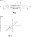
- the slab 1 has a generally rectangular shape, with a total height H equal to 20 cm, measured along the vertical axis Z.
- the slab 1 comprises a first part of slab 2 made of a first concrete.
- the slab 1 comprises a second part of the slab 3 covering at least partially, in this example totally, the first part of the slab 2, the second part of the slab 3 being made of a second concrete, different from the first concrete, the performance of the first concrete being higher than that of the second concrete.
- the first slab part 2 and the second slab part 3, as well as their interface, extend in planes perpendicular to the vertical axis Z.
- the slab 1 extends in a plane perpendicular to the axis vertical Z.
- the slab 1 further comprises at least one connecting element, in this example a plurality of connecting elements, connecting the first part of the slab 2 and the second part of the slab 3.
- the connecting element(s) is/are configured ) and arranged so as to take up a shear force at the interface between the first part of the slab 2 and the second part of the slab 3.
- the first slab part 2 has a height h 1 of 5 cm while the second slab part 3 has a height h2 of 15 cm.
- the second slab part 3 is arranged above the first slab part 2, at least in the final position on site of the slab 1.
- the upper surface 5 of the first slab part 2 is in contact, in this direct example, with the lower surface 6 of the second slab part 3, except of course in the zones occupied by the connecting elements 4.
- the connecting elements 4 are formed in this example by a plurality of connectors 10 each comprising a rectilinear rod, made in this example of metal, in particular of steel, arranged vertically parallel to the axis Z within the slab 1.
- the connectors 10 are all of the same type in this example.
- the connectors 10 comprise a metal stud wrapped in a polymer material.
- the connectors 10 are completely embedded in the slab 1, that is to say projecting neither below the lower surface 7 of the first part of slab 2 nor above the surface upper 8 of the second slab part 3, as visible on the picture 2 .
- the connectors 10 are arranged in rows 11, equidistant within a row 11, the rows 11 also being equidistant from each other.
- a row 11 of connectors 10 is shown on the picture 3 .
- the connectors 10 are not connected to each other other than by the first and the second slab parts 2 and 3.
- the connectors 10 have in this example a Young's modulus E s equal to 200 GPa and a tensile strength f equal to 500 MPa. In this example, the connectors are 13 cm in length.
- the first concrete constituting the first part of slab 2 is in this example an unreinforced fiber-reinforced concrete, the fibers present in the concrete being structural metal fibers, for example the fibers known under the name Dramix ® 3D marketed by the company BEKAERT, having a length between 20 mm and 70 mm, dispersed within the concrete.
- the fibers present in the concrete being structural metal fibers, for example the fibers known under the name Dramix ® 3D marketed by the company BEKAERT, having a length between 20 mm and 70 mm, dispersed within the concrete.
- the second concrete is of the conventional, non-reinforced concrete type.
- the height h 1 of the first slab part 2 which measures 5 cm, corresponds to 25% of the total height H, equal to 20 cm, of the slab 1, the height h2, which is 15 cm, from the second part of slab 3 forming 75% of the total height H.
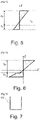
- the cross section of slab 1 remains flat in the deformation. Moreover, in the particular case of slab 1, there is no discontinuity in the deformation at the interface between the two layers, these being considered glued, an effect obtained thanks to the presence of the connecting elements 4 .
- the deformation is continuous even if the Young's modulus varies, which generates a discontinuity of the stress in the first part of slab 2 because the Young's modulus is higher, and decreases the stress in the second part of slab 3 because the elastic modulus is lower, as can be seen on the figure 6 .
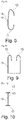
- the figure 8 illustrates the possibility of making the connector 10 C-shaped with the ends of the hooks 12 and 13 connected by a substantially vertical part 14, central.
- the hook 12 forms the lower end of the connector 10 and is intended to extend into the first slab part 2.
- the second hook 13 forms the upper end of the connector 10 and is intended to extend into the second part of slab 3.
- the presence of the hook 13 can be useful for handling the slab 1 during manufacture, in the context of transport from a manufacturing site of the first part of slab 2 with insertion of the connectors 10 to a site of destination for example.
- the connector 10 comprises only the vertical part 14 and only one of the two hooks 12 and 13.
- the connector 10 has a U-shape as in the example of the figure 7 , with, at each free end of the U, a hook shape 15. This hook shape facilitates handling as in the example of the figure 8 .
- the connector 10 comprises a vertical rod 16 as well as a welded head 17 arranged at each end of the vertical rod 16 and extending transversely thereto, that is to say perpendicular to the axis Z once positioned within slab 1.
- the connector 10 comprises only one head 17 at an upper or lower end of the vertical rod 16 and not two as in the example illustrated.
- Such a head 17 or such heads 17 can be useful for lifting the first part of the slab 2 during its transport.
- the connectors 10 each comprise a bolted assembly formed by a bolt 18 which extends from the lower surface 7 of the first slab part 2 and protrudes above the upper surface 8 of the second slab part 3, as visible, and by a nut 19 positioned on each bolt 18 above the upper surface 8 of the second slab part 3.
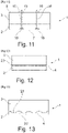
- the connecting element 4 comprises an adhesive composition 20, in the example illustrated formed of a bitumen, placed at the interface between the first part of the slab 2 and the second part of slab 3.
- This adhesive composition 20 was deposited on the first part of slab 2 before casting the second part of slab 3.
- first tile part 2 and the second tile part 3 are in indirect contact with each other, in the zone where the adhesive composition 20 is present, being separated from each other at the level of the interface by the adhesive composition 20.
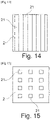
- the connecting element 4 comprises at least one relief 21, in this example a plurality of reliefs 21 formed on the upper surface 5 of the first part of the slab 2 which is intended to be in contact with the lower surface 6 of the second slab part 3.
- the second slab part 3 comprises complementary reliefs 22, as visible.
- the reliefs 21 and 22 form waves, each extending, as seen in the figure 14 , over the entire width (or length) of the first slab part 2.
- each relief 21 forms a stud
- the studs being in this example arranged, at a distance from each other, in the form of a grid with columns and rows.
- the overall shape of the slab 1 can be rectangular with a width and a length of the same order as in the example of the figure 2 and 3 or even 14 and 15.
- the slab 1 can form a beam or sill, with a width much less than the length.
- a beam or sill One such example is illustrated in the figure 16 .
- the overlap between the first slab part 2 and the second slab part 3 is total.
- the second layer of slab 3 only partially covers the first layer of slab 2 as is the case in the embodiment illustrated in the figures 17 and 18 .
- the first slab part 2 forms a rectangle hollowed out at its center by a hollowed-out part 23, substantially square in this example, and the second slab part 3 comprises two portions 3a and 3b covering two sides of the first part of slab 2 and not the recessed part 23 nor all of the two other sides of the first part of slab 2.
- the first slab part 2 can, as in the embodiment illustrated in the figure 19 , comprise on its upper surface 5 at least one reserve 25, two in the example shown, forming a hollow relief to receive a dry or wet network, illustrated in this example by a pipe T for transporting a gas, a liquid or electrical or computer cables.
- the zone of the first slab part 2 occupied by the reserves 25 is not in contact with the second slab part 3, as can be seen, independently of the connecting element 4 used in this embodiment.
- a first step 30 the first part of slab 2 is produced in a first concrete on a site separate from the destination site of the slab 1.
- said at least one connecting element 4 is included in the case where the latter is formed by one or more connectors 10 or reliefs 21.
- the connecting element 4 is formed by an adhesive composition 20, the latter is attached to the first part of the tile 2.
- a step 32 the first part of slab 2 is transported to the destination site of slab 1.
- the second part of slab 3 is produced by pouring the second concrete on the first part of slab 2, or in the desired overlap zones, while the first part of slab 2 is in place on the site. destination.
- the second part of the slab can have a shape which makes it possible, for example, to match the shape of a crosspiece or saddle with its anchoring, in the case of a slab for a railway roadway, for example.
- the first slab part 2 and the connecting element(s) 4 are partially or completely covered so that the slab 1 is formed.
- one or more pipes T can be integrated before casting the second part of slab 3 in the reserve or reserves 25.
- the connecting element 4 is an adhesive composition 20
- the latter can be attached to the first part of the tile 2 either at the manufacturing site of the first part of the tile 2 or when the latter is in place on the site of destination.
- the second slab part 3 is made on the manufacturing site of the first slab part 2, in which case the entirely prefabricated slab 1 is then transported to its destination site.
- the equivalent Young's modulus of the slab 1 is defined.
- the equivalent Young's modulus of the slab 1 can be determined from a weighted arithmetic mean of the thicknesses.
- the Young's modulus is determined using a formula making it possible to obtain a range of values with a minimum Young's modulus and a maximum Young's modulus.
- the dimensions of said at least one connecting element 4, in this example connectors 10, are defined based on the standards, in particular the Eurocode.
- the dimensioning of said at least one connecting element 4, in particular connectors 10, is made in such a way as to join the two slab parts 2 and 3 and allow the operation of the slab 1 formed by the two slab parts 2 and 3 as a single element.
- the connectors are made of steel, they are preferably sized to mainly support the shear forces.
- the dimensions can be obtained by exact modeling and calibrated by dimensioning according to standards, in particular the Eurocode. They can then be confirmed by the modeling of steels in beam of Euler Bernoulli.
- a step 42 an alternative dimensioning to that of the standards is defined, based for example on the criterion of resistance of the steel of the connector 10 and of the behavior of the fiber-reinforced concrete formed by the first concrete.
- this step of the method it is sought to optimize the spacing between the connectors 10, so as to reduce the excess reinforcement. This can make it possible to optimize the shape of the connectors 10 and make it possible to obtain a more efficient geometry than that proposed by the standards, in particular by the Eurocode.
- a rectangular slab of 14cm in height ⁇ 30cm in width ⁇ 150cm in length/depth was made in C20/25 reinforced concrete according to Eurocode standards.
- a rectangular slab of 14cm in height ⁇ 30cm in width ⁇ 150cm in length/depth was made of unreinforced C35/45 concrete according to road and rail pavement standards (NF P 98-086 and EN16432-2) to have the same resistance as the reinforced concrete slab.
- a rectangular slab of 11cm ⁇ 30cm in width ⁇ 150cm in length / depth in height was made of high-performance hybrid concrete, with the first part of the slab 2, the second part of the slab 3 and a plurality of connectors 10 according to the mode of realization of figure 2 and 3 of the invention.
- the height of 11cm was determined to have the same bending strength performance as the other sample slabs.
- the slab design according to the invention makes it possible to reduce the thickness of the slab by 20% and to reduce the carbon footprint by 13.5%.
Landscapes
- Engineering & Computer Science (AREA)
- Architecture (AREA)
- Civil Engineering (AREA)
- Structural Engineering (AREA)
- Bridges Or Land Bridges (AREA)
- Road Paving Structures (AREA)
Applications Claiming Priority (1)
| Application Number | Priority Date | Filing Date | Title |
|---|---|---|---|
| FR2106473A FR3124204B1 (fr) | 2021-06-18 | 2021-06-18 | Dalle pour la construction et procédé de fabrication d’une telle dalle |
Publications (1)
| Publication Number | Publication Date |
|---|---|
| EP4105385A1 true EP4105385A1 (de) | 2022-12-21 |
Family
ID=76807886
Family Applications (1)
| Application Number | Title | Priority Date | Filing Date |
|---|---|---|---|
| EP22179654.3A Withdrawn EP4105385A1 (de) | 2021-06-18 | 2022-06-17 | Bodenplatte für den bau und verfahren zur herstellung einer solchen bodenplatte |
Country Status (2)
| Country | Link |
|---|---|
| EP (1) | EP4105385A1 (de) |
| FR (1) | FR3124204B1 (de) |
Citations (5)
| Publication number | Priority date | Publication date | Assignee | Title |
|---|---|---|---|---|
| US4513040A (en) * | 1983-04-22 | 1985-04-23 | Ribbon Technology, Inc. | Highly wear-resistant steel fiber reinforced concrete tiles |
| CN102561143A (zh) * | 2012-03-09 | 2012-07-11 | 河海大学 | 一种高寒地区混凝土公路路面结构 |
| WO2014094057A1 (en) * | 2012-12-19 | 2014-06-26 | Carbonloc Pty Ltd | A railway sleeper |
| DE202017101111U1 (de) * | 2017-02-28 | 2017-03-11 | C.B.S. Team-Projektgesellschaft mbH | Porenbeton-Hybrid-Bauelement |
| CN112458829A (zh) * | 2020-11-19 | 2021-03-09 | 广东特耐石新材料科技有限公司 | 复合层路面砖的制备方法及应用 |
-
2021
- 2021-06-18 FR FR2106473A patent/FR3124204B1/fr active Active
-
2022
- 2022-06-17 EP EP22179654.3A patent/EP4105385A1/de not_active Withdrawn
Patent Citations (5)
| Publication number | Priority date | Publication date | Assignee | Title |
|---|---|---|---|---|
| US4513040A (en) * | 1983-04-22 | 1985-04-23 | Ribbon Technology, Inc. | Highly wear-resistant steel fiber reinforced concrete tiles |
| CN102561143A (zh) * | 2012-03-09 | 2012-07-11 | 河海大学 | 一种高寒地区混凝土公路路面结构 |
| WO2014094057A1 (en) * | 2012-12-19 | 2014-06-26 | Carbonloc Pty Ltd | A railway sleeper |
| DE202017101111U1 (de) * | 2017-02-28 | 2017-03-11 | C.B.S. Team-Projektgesellschaft mbH | Porenbeton-Hybrid-Bauelement |
| CN112458829A (zh) * | 2020-11-19 | 2021-03-09 | 广东特耐石新材料科技有限公司 | 复合层路面砖的制备方法及应用 |
Also Published As
| Publication number | Publication date |
|---|---|
| FR3124204B1 (fr) | 2023-10-20 |
| FR3124204A1 (fr) | 2022-12-23 |
Similar Documents
| Publication | Publication Date | Title |
|---|---|---|
| FR3029231A1 (de) | ||
| WO2015015103A1 (fr) | Procede d'edification d'un ouvrage en elements prefabriques en beton et ouvrage associe | |
| EP0340051A1 (de) | Brückentafel für eine Brücke mit grosser Spannweite | |
| EP0329517B1 (de) | Schrägkabelbrücke und Verfahren zu deren Bau | |
| EP4105385A1 (de) | Bodenplatte für den bau und verfahren zur herstellung einer solchen bodenplatte | |
| WO2018069524A1 (fr) | Bloc pour construction seche | |
| EP2603637A1 (de) | Gleisschwelle und schaltanlage aus einem verbundstoff | |
| FR2808522A1 (fr) | Composition de beton roule compacte renforce de fibres et procede de realisation d'une chaussee a partir de ladite composition | |
| EP3175057B1 (de) | Ein vorgespanntes tragelement | |
| EP1135565B1 (de) | Triangulierte holzbauweisen, wie gitterträger, brücke, decken | |
| EP2072706B1 (de) | Decke bestehend aus Balken und Deckeneinschüben sowie aus einer nahtlos gegossenen Deckenplatte auf diesen Balken und Deckeneinschüben | |
| EP2060687B1 (de) | Vorrichtung zur Sicherstellung der Isolierung bei thermischer Trennung | |
| EP0005092B1 (de) | Brettförmiges Bauelement und ein derartiges Element umfassende Struktur | |
| EP1031680B1 (de) | Gelenkige paraseismische elastoplastische Vorrichtung für Hoch- und Tiefbau und Brücke mit einer derartigen Vorrichtung | |
| FR2919638A1 (fr) | Elements de structure en beton precontraint comportant des profiles assembles | |
| FR3020646A1 (fr) | Element de construction | |
| WO2019025699A1 (fr) | Procédé de fabrication d'un élément de structure | |
| EP2396482A2 (de) | Durch verriegeln von zwei seitengliedern erhaltener spannbetonbalkenträger und verfahren zum aneinanderfügen von zwei trägern | |
| FR3004737A1 (fr) | Pont en beton | |
| WO2010055227A1 (fr) | Elément de structure comprenant du bois et du béton | |
| FR2940337A1 (fr) | Poutrelle metallique pour la fabrication de planchers | |
| FR2891562A1 (fr) | Element de beton renforce et son procede de fabrication | |
| FR2926309A1 (fr) | Dispositif de liaison par connecteurs pour table de compression ou dalle de plancher. | |
| CH710193A2 (fr) | Elément de structure en béton perforé. | |
| FR2564507A1 (fr) | Montant pour poutre a ame evidee, poutres et ouvrages comportant de tels montants |
Legal Events
| Date | Code | Title | Description |
|---|---|---|---|
| PUAI | Public reference made under article 153(3) epc to a published international application that has entered the european phase |
Free format text: ORIGINAL CODE: 0009012 |
|
| STAA | Information on the status of an ep patent application or granted ep patent |
Free format text: STATUS: THE APPLICATION HAS BEEN PUBLISHED |
|
| AK | Designated contracting states |
Kind code of ref document: A1 Designated state(s): AL AT BE BG CH CY CZ DE DK EE ES FI FR GB GR HR HU IE IS IT LI LT LU LV MC MK MT NL NO PL PT RO RS SE SI SK SM TR |
|
| STAA | Information on the status of an ep patent application or granted ep patent |
Free format text: STATUS: THE APPLICATION IS DEEMED TO BE WITHDRAWN |
|
| 18D | Application deemed to be withdrawn |
Effective date: 20230622 |